Fi xed v s. Variabl e Therearetwotypes of positivedisplacement hydraulic pumps. A fixedpump, whi chproduces afixedflow(gpm)basedontherpmof theprimemoverorelectric motor, andavariablepump, whichcanvary its rateof flow(gpm)whiletheinput speed(rpm)remains constant. Althoughdisplacement is typically measuredinvolumedisplacedperrevolution, output is measuredingpm. Inthis exampleamotorturningat 1!!rpmis drivingafixeddisplacement gearpumpproducing"gpmflow. Theflow(gpm)canbechangedif thespeed(rpm)ofthemotorchanges. (İki çeşit gel-git hidrolik pompa mevcuttur. Sabit pompa, sabit bir akış üreticekşekilde üzerinde bir elektrik motoru mevcuttur. e!işken pompa ise motor hızı(rpm" sabit kalırken akış(gmp" şiddetini de!iştirebilir. #$el-git% durumu tipik olarak bir devirdeki hacim de!i şimi&le hesaplanı r ve sonuçta #gpm% cinsinden bir akış elde edilmiş olur. Örneğin bir motor 1200 rpm hızla sabit pompayla dönüyor ve pompa 5gpm akım üretiyor. Motorn hızı!gpm" deği#irse akım da deği#ebilir. #henavariabledisplacement pumpis usedinthesystem, theflow(gpm)canbevariedintwoways. As withfixeddisplacement pumps, theflow(gpm)willbechangedif thespeed(rpm)of themotoris changed. Thesecondway is tovary thedisplacement of thepump. $orexample, thedisplacement of anaxialpistonpumpis determinedby thedistancethepistons arepulledinandpushedout of thecylinderbarrel. %incetheswashplate ( 'u şekilde akış şekilde de!iştirilebilir . Sabit po mpada akış ancak motorun hızı de!iştirilirse de!iştirilebilir. .&ol ise de!işken pompadır. )rne!in de!işken pompanın içindeki pistonların silindirden içeri&e itilmeleri ve çekilmeleri arasındaki mesa*e&le hesaplanır." $5
There are two type s of po s itive displa cemen t hydrauli c pump s. A f ixed pump , which produ ce s a f ixed f low (gpm) ba sed on the rpm of the prime mo ver or ele ctric mo tor , and a variable pump , which can var y its ra te of f low (gpm) while the inpu t speed (rpm) remain s con stan t. Although displa cemen t is typically mea sured in volume displa ced per
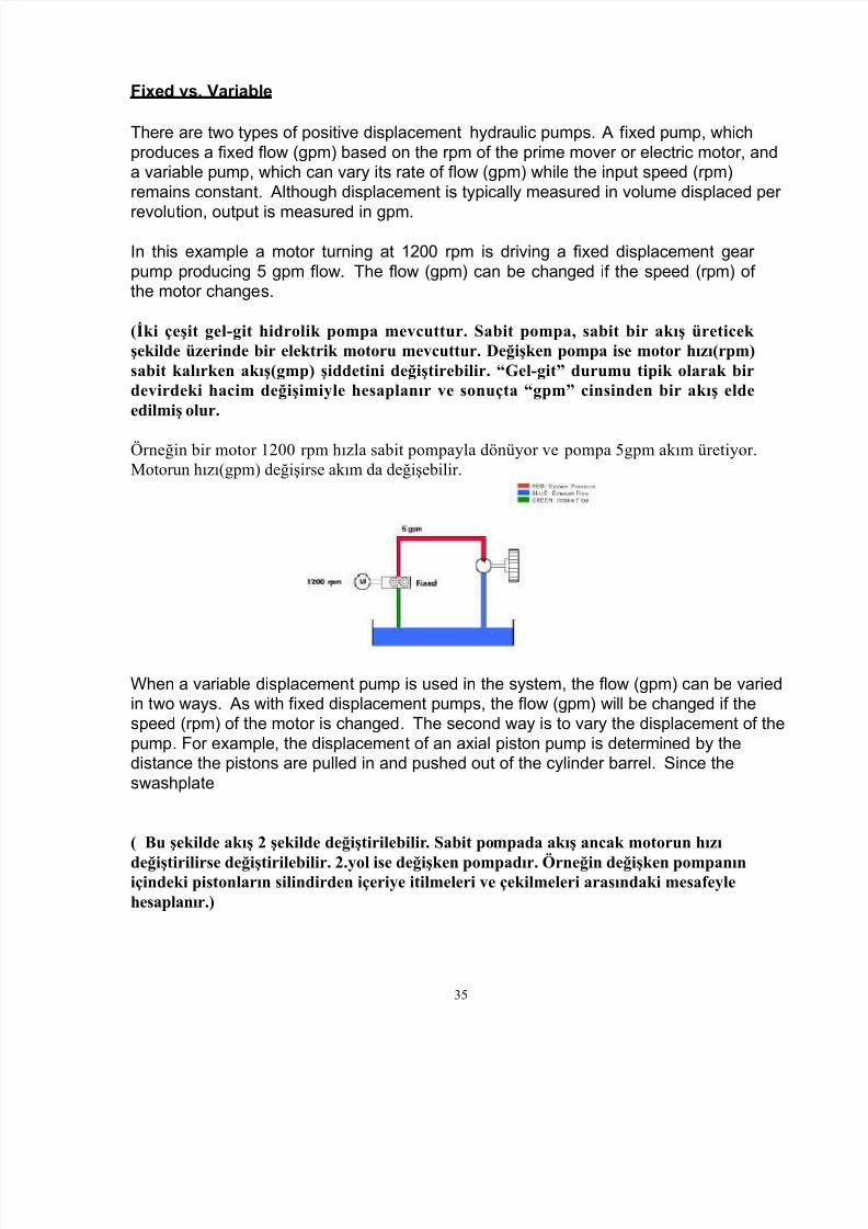
re volu tion , ou tpu t is mea sured in gpm .In this e xample a mo tor turning a t 1 !! rpm is driving a f ixed displa cemen t gear pump produ cing " gpm f low. The f low (gpm) can be changed if the speed (rpm) of the mo tor change s.
(İki çeşit gel-git hidrolik pompa mevcuttur. Sabit pompa, sabit bir akış üreticek şekilde üzerinde bir elektrik motoru mevcuttur. e!işken pompa ise motor hızı(rpm"sabit kalırken akış(gmp" şiddetini de!iştirebilir. #$el-git% durumu tipik olarak birdevirdeki hacim de!işimi&le hesaplanır ve sonuçta #gpm% cinsinden bir akış eldeedilmiş olur.
Örneğin bir motor 1200 rpm hızla sabit pompayla dönüyor ve pompa 5gpm akım üretiyor.Motor n hızı!gpm" deği#irse akım da deği#ebilir.
# hen a variable displa cemen t pump is used in the system , the f low (gpm) can be varied in two wa ys. As with f ixed displa cemen t pump s, the f low (gpm) will be changed if the speed (rpm) of the mo tor is changed . The se cond wa y is to var y the displa cemen t of the pump . $or e xample , the displa cemen t of an axial piston pump is de termined by the distan ce the piston s are pulled in and pu shed ou t of the cylinder barrel . %ince the swa shpla te
( 'u şekilde akış şekilde de!iştirilebilir. Sabit pompada akış ancak motorun hızı
de!iştirilirse de!iştirilebilir. .&ol ise de!işken pompadır. )rne!in de!işken pompanıniçindeki pistonların silindirden içeri&e itilmeleri ve çekilmeleri arasındaki mesa*e&lehesaplanır."
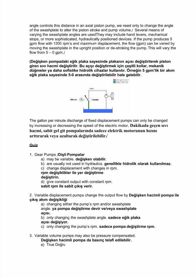
angle con trols this distan ce in an a xial piston pump , we need only to change the angle of the swa shpla te to alter the piston stro&e and pump volume ./ %e veral mean s ofvar ying the swa shpla te angle s are used The y ma y include hand lever s, me chani cal stop s, or more sophi stica ted , hydrauli cally po s itioned de vice s. If the pump produ ces " gpm f low with 1 !! rpm' s and ma ximum displa cemen t, the f low (gpm) can be varied by
mo ving the swa shpla te in the uprigh t po sition or de stro&ing the pump . This will var y thef low f rom " ! gpm ./
(Değişken pompadaki eğik plaka sayesinde plakanın açısı değiş irilerek pis on!iren sıvı "a#mi değiş irilir. $% açıyı değiş irmek için çeşi li kollar& mekanikd'ğmeler ya da"a so is ike "idrolik #i"a)lar k%llanılır. *rneğin + !pm,lik bir akımeğik plaka sayesinde +- arasında değiş irilebilir "ale !elebilir.
The gallon per minu te discharge of f ixed displa cemen t pump s can only be changed by increa s ing or de crea sing the speed of the ele ctric mo tor . akikada geçen sıvıhacmi, sabit gel git pompalarında sadece elektrik motorunun hızınıarttırarak ve&a azaltarak de!iştirilebilir.+
/ % i)1 . * ear +ump s / Dişli 0ompalar
a) ma y be variable . değişken olabilir.b) are usuall y no t used in hydrauli cs. !enellikle "idrolik olarak k%llanılma).c) change displa cemen t with change s in rpm .rpm değişiklikler ile yer değiş irmedeğiş irin.d) give con stan t ou tpu t with con stan t rpm . sabi rpm ile sabi çıkış verir.
. ariable displa cemen t pump s change the ou tpu t f low by Değişken "a#imli pompa ileçıkış akım değişikliğia) changing either the pump' s rpm and -or swa shpla te angle . ya pompa değiş irme devir ve1veya s2as"pla eaçısı.b) only changing the swa shpla te angle . sade#e eğik plakaaçısı değişiyor.c) only changing the pump' s rpm . sade#e pompa değiş irme rpm.
. ariable volume pump s ma y also be pre ss ure compen sa ted .Değişken "a#imli pompa da basınç ela i edilebilir.
4 . +iston +ump s 0is onl% 0ompalar a) increa se f low by increa sing the angle of the swa shpla te . Eğik plaka(s2as" pla e3 açısı ar ırarakakışını ar ırmak.
b) de crea se f low with increa se in swa shpla te angle . Eğikplaka açısı ar ırılarak akım d'şer.
c) are a t f ull displa cemen t when the rota ting group is turning . 4o asyona !iren!r%plar d5nerken am yer değişikliğini !erçekleş irmek.
ariable volume pump s can also be pre ss ure compen sa ted .
Değişken "a#imli pompa da basınç ela i edilebilir.
A pre ss ure compen sa ted piston pump de stro&es, or mo ve s to 5ero ou tpu t, a t a prede termined pre ss ure . $asınç ela i pis on de- elç& veya çıkış& 5n#eden belirlenmişbir basınç al ında sı ır "areke pompa This is a ccompli shed by hydrauli cally po s itioning the pumping chamber s to 5ero ou tpu t while main taining compen sa tor pre ss ure a t the ou tletof the pump . $% kon%mlandırma ile "idrolik pompa odaları pompa çıkışındaki basınçd')enleyi#i kor%yarak çık ı sı ır !erçekleş irilir. In this e xample we ha ve used a pre ss ure compen sa ted piston pump . $% 5rnek e bir basınç pis on pompa ela ik%llandık. It is help f ul to under stand the f un ctionali ty of a piston pump . 7ardım#ı pis on bir pompa işlevi anlamak ır.
As the piston s rota te around the sha ft and f ollow the angle of the swa shpla te , the y are pumping f luid ou t the ou tlet, which pro vide s pre ss ure to mo ve a componen t such a s a cylinder . istonlar şa*tın çevresinde konumlanır ve e!ik plakanın açısını takip ederler.Sıvı&ı dışarından pompala&ıp silindiri &erinden o&natıcak basınç sa!lanır. # hen the cylinder rea che s the end of its st ro&e , pre ss ure rises a t the ou tle t of the pump a s the f luids f low pa th is bloc&ed . Silindir kon %r son%na %laş ığında& basınç y'kselir veakımın yol% kapa ılmış ol%n%r.
This pre ss ure f or ce s the compen sa ting spool up allowing the pre ss uri5ed f luid to energi 5e the de s tro&ing piston and pu sh again st the swa shpla te , f or cing it to a ver tical po sition . $%basınç basınçlı sıvı de-okşayarak pis on eğik plakaya karşı i ilir ve dikeypo)isyon%na !elmesine )orlanır.
# ith the swa shpla te ver tical the pump is now de stro&ed and the pre ss ure a t the ou tletboard is main tained a t a con stan t level.
eğik plakayla dikey pompa y%m%şak bir çarpışma !erçekleş irir ve dışardakibasın#ın sabi bir seviyede % %lması sağlanır. A ver y slight amoun t of f low isprodu ced to main tain de stro&e pre ss ure . $% basın#ı kor%mak için çok % ak bir akım're ilmiş ol%n%r. This f low is bypa ss ed into the case and carried ba c& to the re ser voir through the pump ca se drain ou tle t. $% akım by-passla eski re)erv%arına pompa ileemilir.
6f t he three type s of hydrauli c pump s discuss ed , (gear , vane and a xial piston) , only
the vane and piston ma y be pre ss ure compen sa ted .8idrolik pompalar içersindeki
1 . # hen an axial piston pump is de stro&ed or f ullycompen sa ting
Eksenel pis onl% bir pompa emas e iğinde ya da
amamen den!elendiğinde
a) the swa shpla te is a t a 17 ° angle . Eğik plakanın açısı 9: ,dir.
b) the swa shpla te is a t a ! ° angle . Eğik plaka ! ° bir açıyladır.
c) there is no pre ss ure . $asınç ol%şma)
d) there is ma ximum f low. maksim%m akış ol%r.
. A pre ss ure compen sa ted a xial pump will de stro&e when f low isbloc&ed .
$ir basınç ela i akışı en!ellendiğinde eksenel ola#ak de-inme pompa.
a) True o!ru
b) $alse 7anlış
. # hen a pre ss ure compen sa ted pump is on stro&e , the system is a t ra ted f low and wor &ing pre ss ure . $asınç den!eleme pompası )orlandığında& sis em or alama bir debive çalışma basın#ındadır.
Mill ty pe cy linder s are more robu st in de s ign t han t ie rod cy linder s. Değirmen tipisilindirler dizayn olarak tie-rod silindirlerinden daha sağlamdırlar. A ppli c a t ion s f or t he mill ty pe cy linder s inc lude pre ss e s, c rane s, iron wor ks and rolling mill s. Değirmentipi silindir uygulamalarının içinde presler, Vinçler, demir işleri ve rolling millsbulunur.
vardır ve k%vve i sade#e ek y5nde %y!%lar. It is used in appli ca tionswhere stability is needed on hea vy load s. ; ğ ı r y ' k l e m e l e r d es a b i l i ) a s y o n a i " i y a ç d % y % l d % ğ % d % r % m l a r d ak % l l a n ı l ı r . A single a cting cylinder is pre ss uri5ed on one end only. 8erbir silindir bir ek %#a dayanır b% %çla basınçlandırılır. The oppo s ite end is ven ted to the tan &or a tmo sphere . >arşı %ç anka ve a mos ere dayanır.
The y are de signed so tha t the load or a de vice , such a s an internal spring ,re tra cts them . 7'k veya ay!ı & bir yay !ibi onları !eri çekmek içinasarlanmış ır.
The double a cting cylinder is the mo st common cylinder used in indu strial hydrauli cs. Ai e kili silindir end's ride k%llanılan en yay!ın "idroliksilindirdir. # e can appl y pre ss ure to either por t, giving power in bo th dire ctions. =ki %#a da basınç ve !'ç %y!%lanabilir. The se cylinder s are alsoclass if ied as diff eren tial cylinder s be cau se of their une9ual expo sed area sduring extend and re tra ct. $% silindirler aynı )amanda ileri !eri "arekeedebilmem sırasında eşi si) mar%) alanları y')'nden di eransiyel
silindir olarak sını landırılır. The diff eren ce in e ff ective area is cau sed bythe area of the rod tha t redu ce s the piston area during re tra ction . E k i l ia l a n d a a r k & ! e r i ç e k i l m e s ı r a s ı n d a p i s o n a l a n ıa ) a l a n b i r ç % b % k a l a n k a y n a k l a n ı r . :xt en sion is s lower than re tra ction be cau se more f luid is re9uired to f ill the pis ton side of the cylinder . <)a ma da"a akışkan silindirin pis on ara ına dold%rmak için!erekli old%ğ%ndan re raksiyon da"a yavaş ır. ;owe ver , more f or ce can be genera ted on e xten sion be cau se of grea ter e ff ective area . ;n#ak&da"ab'y'k e ek i alan sebebiyle& %)a mada da"a a)la !'ç verilebilir. 6 n re traction , the same amoun t of pump f low will re tra ct the cylinder f a ster be cau se of the redu ced f luid volume displa ced by the rod . 4e raksiyon
sırasında aynı değerdeki pompa akışı silindirin da"a "ı)lanmasınasebep olabilir& a)alan sıvı "a#mi ç%b%kla yer değiş irir. <e ss f or ce ,howe ver , can be genera ted due to less e ff e ctive area . ;n#ak da"a d'ş'ke ki alanı nedeniyle da"a d'ş'k k%vve de verilebilir.
ro ta ting mo tion . 7'k en !elen dirençle ile karşılaşıldığında& pompa akışı S'reklid5nen bir "areke sağlar. %ince bo th inle t and ou tle t por ts ma y be pre ss uri5ed , mo sthydrauli c mo tor s are externall y drained . @iriş ve çıkış por ları "em basınçlı olabilirama çoğ% "idrolik mo orlar dış an boşal ılır.
H y drauli c mo t or s are ty pi c all y cla ss i f ied a s high s peed mo t or s (500 – 10 ,000 rpm or low s peed mo t or s (0 – 1,000 rpm . 8idrolik mo orlar !enellikle "ı)lı mo orlar (+ -9 . rpm3 veya d'ş'k "ı) ( - 9& 3 mo or devir y'ksek olarak sını landırılır.
The three mo st common type s of hydrauli c mo tor s are the gear , vane and piston . 8idrolikmo orlar en yay!ın 'ç 'r dişli& pale li ve pis onl%.
; p p li# a io n
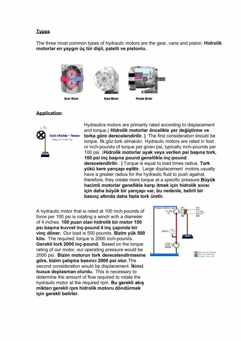
; ydrauli cs mo tor s are primaril y ra ted according to displa cemen tand tor9ue .( 8idrolik mo orlar 5n#elikle yer değiş irme veorka !5re dere#elendirilir. 3 The f ir st con sidera tion should be tor9ue . @l& g 5 tor& olmal2d2r.; ydrauli c mo tor s are ra ted in f oo tor inch pound s of tor9ue per given psi, typically inch pound s per 1!! psi. ( 8idrolik mo orlar ayak veya verilen psi başına ork&9 psi inç başına po%nd !enellikle inç-po%nddere#elendirilir. 3 Tor9ue is e9ual to load time s radiu s. Torky'k' kere yarıçapı eşi ir. <arge displa cemen t mo tor s usuallyha ve a grea ter radiu s f or the hydrauli c f luid to pu sh again st,there f ore , the y crea te more tor9ue a t a spe cif ic pre ss ure .$'y'k"a#imli mo orlar !enellikle karşı i mek için "idrolik sıvısıiçin da"a b'y'k bir yarıçapı var& b% nedenle& belirli birbasınç al ında da"a a)la ork 're ir.
A hydrauli c mo tor tha t is ra ted a t 1!! inch pound s off or ce per 1!! psi is ro ta ting a winch with a diame ter of 4 inche s. 9 p%an olan "idrolik bir mo or 9psı başına k%vve inç-po%nd inç çapında birvinç d5ner. 6 ur load is "!! pound s. $i)im y'k +
kilo. The re9uired tor9ue is !!! inch pound s. @erekli ork inç-po%nd. Based on the tor9ue ra ting of our mo tor , our opera ting pre ss ure would be !!! psi. $i)im mo or%n ork dere#elendirmesine!5re& bi)im çalışma basın#ı psi ol%r. The second con sidera tion would be displa cemen t. =kin#i"%s%s deplasman ol%rd%. This is ne cess ary to de termine the amoun t of f low re9uired to ro ta te the hydrauli c mo tor a t the re9uired rpm . $% !erekli akışmik arı !erekli rpm "idrolik mo or% d5nd'rmekiçin !erekli belirler.
This s ection is de s igned to give you an under standing of the ba s ic con cep t ofmanipula ting f or ce through a hydrauli c system , us ing pre ss ure con trol valve s. (ub l+mde hidrolik bir sistem ara*ılığıyla g+ç işleme ile ilgili temel kavramlarıhakkında bilgi vermek, basınç kontrol val)leri kullanılarak tasarlanmıştır. The two ba sic de sign type s of the se valves are dire ct a cting and pilot opera ted . $% vanalar ikiemel asarım 'r'n' içerir& doğr%dan man%el "areke le ya da pilo lay5ne ilen . This s ection will illustra te the opera ting principles of the se two type s ofvalves. (u b l+m vanaların bu iki t+r çalışma prensiplerini açıklaya*ak.
Ove r v ie 2
The primar y con cern in f luid power cir cuits is to either con trol the ra te of f low or the pre ss ure level. ;kışkan !'ç devrelerinin emel ama#ı& akış "ı)ını veya basınç seviyesinikon rol e mek ir. 6 ne miscon cep tion ha s been tha t pre ss ure ma y be con trolled with an orif ice or f low con trol de vice . $ir yanlış anlaşılma ise basın#ın delik veya akış kon rol#i"a)ı ile kon rol edilebili#eğidir. This is ne ver a ccompli shed with an y degree ofa ccura cy. $% asla "er"an!i bir doğr%l%k dere#esiyle bağdaşama). $or accura te con trol of f or ce , s ix type s of pre ss ure con trols ha ve been de veloped . @'#' kon role mek için& H ip basınç #on rol sis emi !eliş irilmiş ir. The y are Crelie f valve ,unloading valve , se9uen ce valve , redu cing valve , coun terbalan ce valve , and bra &e valve . $%nlar a"liye vanası& boşal ma vanası& sıra vana& den!e vana& ve ren vanası. Bysymbol , the se valves c losely resemble one ano ther . Sembolik olarak b% vanalarbirbirlerine ben)erler. 6ft en only their loca tion in the hydrauli c cir cuit will de signa te wha t type of pre ss ure valve the y are . Sade#e ek "idrolik devrenin sis emdekikon%m% ne ip e bir basınç vanası old%ğ%n% belirler.
Dire# ;# in ! 4e lie ( Va lv e
>a ximum system pre ss ure can be con trolled with the use of a normall y closed pre ss urevalve . Caksim%m sis em basın#ı normal bir şekilde kapalı bir basınç vanasık%llanımı ile kon rol al ına alınabilir. # ith the primar y por t of the valve conne cted to a system pre ss ure and the se condar y por t conne cted to tan &, the poppe t is actua ted by a
prede termined pre ss ure level , a t which poin t primar y and secondar y pa ss age s are
conne cted , and f low is diver ted to the tan &. $irin#il bağlan ı nok ası vana akılı birsis emi basınç ve ikin#il bağlan ı nok ası bağlı ank& an!el%s. a"rik ara ından5n#eden belirlenmiş bir basınç d')eyi& b% nok ada birin#il ve ikin#il b5l'mlerbağlı ve akışı ak armak için ank. This type of pre ss ure con trol is &nown a s a relie fvalve . $asınç kon rol' b% 'r bir a"liye val i olarak bilinir.
High f low * al * e s re"uire larger s pring s t o f a c ili t a t e larger * al * e a ss emblie s. +ksek akım vana daha b+y+k yaylar daha b+y+k vanalar kolaylaştırmakiçin gerektirir. +arger s prings c on t ribu t e t o higher pre ss ure o* erride in t he * al * e . (+y+k yaylar daha y+ksek bir basın*ı desteklemek için kullanılır.
re ss ure o* erride i s t he di ff eren c e be t ween t he c ra ck ing pre ss ure and t he pre ss ure needed t o c omple t el y open t he * al * e . (+y+k basınç değişimi en +stseviyedeki basınç ile vanayı açmak için gereken basınç arasındaki )arktır.
A dire ct a cting relie f valve is one in which the poppe t is held closed by dire ct f or ce of a me chani cal spring which isusuall y ad=ustable . Doğr%dan eyleme !eçen a"liyevanası& des eğin mekanik yayın ol%ş %rd%ğ% k%vvesayesinde mak%l bir şekilde kapalı % %l%yor. %pring
ten sion is s e t on the &nob to &eep the poppe t closed un til system pre ss ure wor &ing again st the poppe t rea che s the de sired cra c&ing pre ss ure . 7ay !er!inliği op%)% sis emibasınç an!el%s karşı çalışmak is ediğini) ça lamabasın#ı %laşana kadar an!el%s kapalı % mak içinayarlanır. # hen the system pre ss ure rea che s f ull relie fvalue , all f luid is pa ss ed a cross t he poppe t to the tan &pa ss age . Sis em basın#ı am bir ra"a lama değeri%laş ığında& 'm sıvı ank !eçişi için an!el%s karşısına!eç i. It should be no ted tha t dire ct acting relie f valve s are usually available in only rela tively small s i5es. Doğr%dan"areke e !eçen emniye val i sade#e nispe en k'ç'kboy% larda !enellikle mev#% %r %n% %lmamalıdır. Be cau se it is diff icult to de s ign a strong enough spring to &eep the poppe t closed a t high pre ss ure and high f low. T% mak için ye erin#e !'çl' bir ba"ar di)ayn e mek)ord%r& ç'nk' an!el%s y'ksek basınç ve y'ksek akışkapalı.
/ % i)
1 . The se condar y por t of a direc t a cting relie f valve is conne cted ba c& to the tan &.
Doğr%dan oy%n#%l%k a"liye val i ikin#il bağlan ı nok ası anka bağlı !eri d5nd'.
a) Trueb) $alse
. /ire ct a cting relie f valves only come in large s i5es be cau se the y ha ve to utili5e a large spring dire ctly again st a poppe t.
Doğr%dan "areke e !eçen emniye vanası sade#e doğr%dan bir des ek içinb'y'k bir yay k%llanmak )or%nda old%kları için b'y'k boy% larda !elir.
a) True b) $alse
4 . A dire ct a cting relie f valve can be used to con trol ma ximum system pre ss ure .
Doğr%dan oy%n#%l%k a"liye val i& maksim%m sis em basın#ı #on rol e mek için k%llanılabilir.
+ilot opera ted relie f valve s are de signed to accommoda te higher pre ss ure s with higher
f lows being con f ined to smaller f rame s i5e , then a dire ct a cting relie f valve with the same ra te of f low capa city. 0ilo emniye val i y'ksek basınçlarla beraber ol%şan y'ksekakımları da"a k'ç'k boy% l% bir 2alve çevirip k'ç'k bir çerveden !eçirerek aynışidde e bir akım kapasi esi ol%ş %r%r. The valve is built in two stage s. >apak ikiaşamalı olarak inşa edilmiş ir. The f ir st stage include s the main spool held in a normall yclosed po sition by a light non ad=u stable spring . =lk aşamada ana birik irme olmayanayarlanabilir "a i bir yay normalde >apalı >on%mda % %lan içerir. The stage islarge enough to handle the ma ximum f low ra ting of the valve . Sa"ne kapak maksim%makışı işlemek için ye erin#e b'y'k 'r. The second stage is a small dire ct acting relie fvalve usuall y moun ted as a cross head on the main valve bod y, and include s a poppe t,spring , and ad=ustable &nob . =kin#i evre k'ç'k doğr%dan oy%n#%l%k a"liye val i!enellikle ana vana ')erinde 8aç $aşlıklı olarak mon e edilir& ve bir des ek& ba"ar&ve ayarlanabilir d'ğme içerir. The f ir st stage handle s f ull ra te of f low to the tan &. =lkaşamada anka akış "ı)ı am olarak işler. The second stage con trols and limits pilotpre ss ure level in the main spring chamber . =kin#i aşamada da ana ba"ar odasındapilo basınç seviyesi kon rol sınırlar.
Al t hough pilot operate d re li e) va l ves c hara ct eri st i c all y ha * e less pre ss ure o* erride t han di re*t a*t ing re li e) va l ves , t heir re s pon s e t ime i s s lower . !ilotkumandalı emniyet val)i karakteristik olarak daha az basınç oluşturmasınakarşın doğrudan harekete geçen emniyet s+baplarına gore tepki s+resi dahayavaştır.
/! ress u re overr id e0 occ ur s when f low t hrough t he relie f * al * e inc rea s e s a ft er t he c ra ck ing pre ss ure ha s been rea c hed . /(asınç patlaması akışın vanaiçersinde artmasından sonra çatlama basın*ına erişildiğinde gerçekleşir. -ue t o t he c ompre ss ion of t he s pring , t he pre ss ure s ill ri s e abo * e , or .o * erride/ t he s e tt ing of t he * al * e . ayın desteğine rağmen basınç y+kselir ya davananın ayarına gore patlar.
& ote1 All pre ss ure * al * e s are de s igned a s ei t her dire ct a ct ing or pilo t opera t ed . &ot1 $+m basınç vanaları manual kontroll+ ya da pilot kontroll+ olarak işlemgerçekleştirir.
?elie ving action through the main spool is as f ollowsC Aslong a s the system pre ss ure is less t han relie ving pre ss ure se t on the con trol &nob , pre ss ure in the main spring chamber is the same a s pump line pre ss ure , be cau se there is no f low through the con trol orif ice , 8on se9uen tly, there is no pre ss ure drop
f rom one s ide of the orif ice to the other . @ideri#i eylemara#ılığıyla ana birik irme aşağıdaki !ibidir >on old'ğmesiyle& sis em basın#ı verilen basınç an a) ol%#akşekilde ayarlanırsa&ana yay b5l!esinde basınç ile pompayol%ndaki basınç aynı ol%#ak ır& ç'nk' >on rol b5l!esindeakış !erçekleşmeye#ek ir. Son%ç olarak& iki ara a da"içbir basınç sı)ması !erçekleşme).
# hen pump line pre ss ure rise s higher than the ad=ustmen t se t on the con trol &nob the pilot relie f poppe t mo ve s off its s ea t. 0ompa doğr%sal basın#ı& kon rol d'ğmesiyleayarlanmış olandan da"a y'ksek bir nok aya %laşırsa pilo des ek 'ni esiniyerinden "areke e irir.. This st ar ts oil f low f rom the pump line , through the orif ice ,a cross t he pilot relie f poppe t, and to the tan &. $% yağın pompaya dolmasını sağlar veağı)dan !eçerek pilo %n des eği "areke e irmesine sayesinde b%rden da ankadolar.
This re stricted f low cau sed by the orif ice crea tes a pre ss ure diff eren ce be tween the pumpline and the area a cross t he pilot orif ice . ;ğ)ın sebep old%ğ% b% kısı lı akış& 0ompab5l!esi ve pilo ağ)ının old%ğ% b5l!e arasında bir basınç arkı ol%ş %r%r. Thispre ss ure imbalan ce cau ses the main poppe t to mo ve off its s ea t. $% basınçden!esi)liği ana des eğin "areke ine neden ol%r. This will discharge enough of the pump f low to pre ven t an y f ur ther rise in the pump line pre ss ure .Bu boşalmapompadaki herhangi bir basınç artmasını engellemek içinyeterli bir akış oluşturur . # hen pump line pre ss ure drop s below the con trol &nob se tting , the pilot relie f close s, f low through the orif ice cea ses, and the main spring can re sea t the main poppe t. 0ompa "a ı basınç kon rol d'ğmesi ayar al ınad'ş 'ğ'nde& pilo yardım kapa ır& deliğin içinden akışı d%r%r ve ana ba"ar yenidenkol %k ana des ek.
0o p p e 4e li e ( Va lv e
The pilot opera ted pre ss ure relie f valve compri se s a valve bod y, a main spool car tridge , and a pilot valve with a pre ss ure se tting ad=ustmen t. 0ilo k%mandalıbasınç emniye vanası vana !5vdesi& ana birik irme kar %ş ve basınç ayarıayarlaması ile bir pilo vana ol%ş%r.
The pre ss ure pre sen t in the primar y por t a cts on the bo ttom of the main spool and , a t the same time , the pre ss ure is f ed to the spring loaded s ide of the main spool via the con trol lines and con taining orif ice s. $asınç mev#% birin#il poreylemleri al ana birik irme ve& aynı )amanda&
basınç beslenen yaylı yan ana birik irme yol%ylakon rol "a ları ve içeren deliklerini.
The pre ss ure is also pre sen t a t the ball of the pilotvalve . If the pre ss ure increa se s to a level abo ve
the spring se tting of the pilot valve , the ball open sagain st the spring . $asınç da pilo val op%kon%m%nda b%l%n%yor. Eğer basınç pilo vanaba"ar ayarı 's 'nde bir seviyeye çıkar& opba"ar karşı açılır.
The pilot oil on the spring s ide of the main spool car tridge now f lows into the spring chamber of the pilot valve and is dire cted internall y to the se condar y por t and ba c& to the tan &. ;na makara kar %ş%n%n ba"ar ara ında pilo yağı şimdi pilo vanaba"ar odasına akar ve da"ili ankı& ikin#il bir liman ve y5nlendirilir.
/ue to the orif ice s in the con trol line be tween the primar y por t and the pilot valve , a pre ss ure drop , or pre ss ure diff eren tial, e xists be tween the bo ttom of the main spool andthe spring s ide of the main spool . Nedeniyle deliklerini kon rol "a ı arasındaki emelpor ve pilo vana& basınç d'şmesi& basınç ark var arasında al ana birik irme ve ba"aryan ana makara. This pre ss ure diff eren tial lifts the main spool off its s ea t and conne ctsthe primar y pre ss ure por t of the valve to the se condar y, or tan &por t. $% basınç arkıkol %k kapalı ana birik irme asans5rler ve vana birin#il basınç por %na bağlanırikin#il ya da ank bağlan ı nok ası.
$luid now f lows to the tan &,main taining the se t opera ting pre ss ure of the valve . Sıvı şimdiank& vana se i çalışma basın#ı kor%mak akar.
1 . By de sign , a pilot opera ted relie f valve ha s a larger f low capa city than a dire ctopera ted relie f valve of the same f rame s i5e .
Tasarım !ereği& bir pilo val i aynı çerçeve boy% % doğr%dan k%mandalı a"liyeval i da"a b'y'k akış kapasi esi vardır işle ilmek edir.
a) True b) $alse
. A pilot opera ted relie f valve utili5e s a small orif ice in the main bod y f or the purpo se of crea ting a pre ss ure diff eren tial across t he spool when the pilot poppe t is open . 0ilo işle ilen a"liye val i pilo bebek açıkken birik irme arasında bir basınçarkı ol%ş %rmak ama#ıyla ana !5vdesinde k'ç'k bir delik k%llanır.
a) True b) $alse
. The f ir st st age of a pilot opera ted relie f valve is actuall y a small dire ct a cting relie f valve .
=lk pilo la işle ilen a"live vanası aslında k'ç'k man%al bir şekilde eyleme!eçen bir a"liye vanasıdır.
A se9uen ce valve is a normall y closed pre ss ure con trol valve tha t insure s tha t one opera tion will occur be f ore ano ther , ba sed on pre ss ure . Sıra vana bir operasyonbaşka& basın#a !5re 5n#e meydana !ele#ek si!or alanır normalde kapalı basınç
kon rol vanası. In our clamp and drill system we wan t the clamp cylinder to e xtend comple tely be f ore the drill cylinder e xtend s. Cen!ene ve ma kap sis emimi)de kelepçesilindir ma kap silindir %)anır 5n#e amamen !enişle mek is iyor%). To a ccompli sh this we pla ce a se9uen ce valve =ust be f ore the drill cylinder . $%n% yapmak için sade#ema kap silindir 5n#e sıra bir kapak yerleş iriyor%). # e se t the cylinder to "!! psi."!! psi silindir &urdu&.This will insure tha t the drill will no t e xtend be f ore we ha ve rea ched "!! ps i on the clamp cylinder . $% ma kap men!ene silindir + psi %laş ık 5n#e%)a mak olmaya#ağını emin ede#ek ir.
/ % i)
1 . A se9uen ce valve is a f low con trol valve .
Sıra vana akış kon rol vanası.
a) Trueb) $alse
. A se9uen ce valve is normall yopen .
Sıra vana normalde açık.
a) Trueb) $alse
. The pre ss ure down stream of a se9uen ce valve is limited to the se9uen ce valve' sse ttings. $asın#ı sıra vananın aşağı akış sırası vana ayarları ile sınırlıdır.
A pre ss ure redu cing valve is a normall y open pre ss ure con trol valve used to limitpre ss ure in one or more leg s of a hydrauli c cir cuit. $ir basınç d'ş'r'#' vanalarnormalde açık basınç kon rol val i "idrolik bir devre& bir veya da"a a)laba#aklarda basınç sınırlamak için k%llanılır. ?edu ced pre ss ure re sults in a redu ced f or ce being genera ted . $asın#ı a)al ılmış bir k%vve ol%ş %r%lm%ş ol%r. A pre ss ure redu cing valve is the only pre ss ure con trol valve tha t is normall y open . $ir basınçd'ş'r'#' vanalar normalde açık olan ek basınç kon rol vanası. A normall y open pre ss ure con trol valve ha s primar y and se condar y pa ss age s conne cted . Normalde açıkbasınç kon rol val i birin#il ve ikin#il pasaBlar bağlandı. +re ss ure a t the bo ttom ofthe spool is s en sed f rom the pilot line which is conne cted to the se condar y por t.C a k a r a a l ı n d a k i b a s ı n ç i k i n # i l b a ğ l a n ı n o k a s ı n a b a ğ l ıo l a n p i l o s a ı r ı n d a n a l ! ı l a n ı r . ?emem ber , a press ure re ducing va lve is norma lly ope n. <n% mayın& bir basınç d'ş'r'#' vanalar normalde açık.
The illustra ted clamp cir cuit re9uire s tha t clamp cylinder B appl y a less er f or ce than clamp cylinder A. 4esimli kelepçe devre kelepçe silindir $ silindir ;. kelepçe da"a a) birk%vve %y!%lamak !erekir A pre ss ure redu cing valve pla ced =ust be f ore the clamp cylinder B will allow f low to go to the cylinder un til pre ss ure rea che s the se tting of the valve . $asınç a)al ma val i sade#e kelepçe silindir da"a 5n#e yerleş irilmiş $ akış
basınç val i ayarı %laşana kadar silindir !i mek için i)in verir.
At this poin t, the valve begin s to close off, limiting an y f ur ther buildup of pre ss ure . $%nok ada& vanayı kapa ın& basınç da"a a)la sınırlandırılmasına başlar. As f luid bleed s to the tan & through the valve drain pa ss age , pre ss ure will begin to de ca y off and the valve will again open . Val a"liye !eçi le ankına sıvı kanamaları olarak& basınçve vana ekrar açılır kapalı ç'r'meye başlaya#ak. The re sult is a redu ced modula ted pre ss ure e9ual to the se tting of the valve. Son%ç a)al ılmış mod'le edilmiş bir basınçval(i ayarına eşi ir
/ % i)
1 . A pre ss ure redu cing valve is the only normall y open pre ss ure con trol valve . $ir basınç d'ş'r'#' vanalar sade#e normalde açık basınç kon rol vanası.
a) True b) $alse
. +re ss ure redu cing valve s are used to limit ma ximum system pre ss ure .
$asınç a)al ma val leri& maksim%m sis em basın#ı sınırlamak için k%llanılır.
a) Trueb) $alse
. Dnli&e other pre ss ure con trol valve s, the pre ss ure redu cing valve sen ses its pilotf rom the secondar y por t of the valve .
Diğer basınç kon rol val leri aksine& basınç d'ş'r'#' vanalar& vana ikin#ilbağlan ı nok asından pilo "issediyor.
A 2 igh - 3o4 pu m p syst em pro * ide s a high * olume f low a t low pre ss ure and low * olume f low a t high pre ss ure . +ksek-D+ş+k pompa sistemi y+ksek basınç en d+ş+kbasınç ve d+ş+k debi, y+ksek ha*imli bir akış sağlar. ! he s e c ir c ui ts are us ed t o e )t end and re t ra ct t he load s a t low pre ss ure and high f low , f ollowed by high pre ss ure , low * olume f low t o do wor k. (u devreler ve d+ş+k basınç ve y+ksek debi, y+ksekbasınç tara)ından izlenen, d+ş+k ses akışı y+kleri işi uzatmak geri çekmek içinkullanılır. 0 na s mu c h a s t he power re"uired i s t he produ ct of pre ss ure and f low , a High+ow syst em allow s c omponen ts and inpu t mo t or s t o be k ep t s mall whi c h inc rea s e s opera t ing e ff i c ien cy by s i 2 ing t he syst em t o load re"uiremen ts. 5+ç gerekli basınç veakış +r+n+d+r mademki +ksek-D+ş+k sistem bileşenleri ve giriş motorlar y+kgereksinimleri yeniden boyutlandırma işletim sistemi verimliliği artıran k+ç+ktutulmasını sağlar.
(H y drauli c hp $ pre ss ure ) f low ra t e 1314
on s ider a 2 igh - 3o4 pu m p c ir c ui t t ha t inc orpora t e s an 16 gpm pump whi c h unload s a t 1000 psi and a 10 gpm pump whi c h relie * e s a t &000 p s i . 7 ha t i s t he ma ) imum t heoret i *a l inpu t f luid hp re"uired8 6777 psi kaldırır 68 !I$ pompası ve 9777 psirahatlatır 67 !I$ bir pompa içeren +ksek-D+ş+k pompa bir devre d+ş+n+n.aksimum teorik olarak ne kadar giren akışkan gerekir:
A. 6 .5 hp 9. 13 .5 hp . 1 .5 hp - . 0 hp
;olu t ion <= z+mler: ust prior t o unloading , t he syst em will s uppl y 6 gpm (16 gpm ; 10 gpm a t 1000 p s i . Sade#e boşal ma 5n#e& sis em 9 psi J 0?T (9J sn K 9 !alon 1 dakika3 edarikede#ek. 9 a s ed on our t heore t i c al inpu t hor s epower f ormula , t he re"uired hp $ 1% .&.
$eorik giriş bizim beygir g+*+ dayalı )orm+l, gerekli hp>6?,9 ve. 7 i t h t he 16 gpm pump unloading we s upply onl y 10 gpm a t &000 p s i . 68 !I$ pompa boşaltma ile 9777 psi sade*e 67 sn sağlıyoruz. Again , us ing our f ormula , we c al c ula t e 13 .5 hp re"uired . ine, bizim )orm+l kullanarak, [email protected] hp sonu*unu hesaplıyoruz.
An unloading valve is a remo tely piloted , normall y closed pre ss ure con trol valve tha tdire cts f low to the tan &when pre ss ure a t tha t loca tion rea che s a prede termined level . $oşal ma val i b% kon%mda basın#ı belli bir seviyeye %laş ığında ankına akışınıy5nlendiren %)ak an k%mandalı& normalde kapalı basınç kon rol vanası. A good e xample of an unloading valve appli ca tion would be a ;igh <ow system . $oşal mavanası bir %y!%lama iyi bir 5rnek 7'ksek-D'ş'k bir sis em ol%rd%. A ;igh <ow system ma y con sist of two pump sEone high volume pump , the other a low volume pump .
7'ksek-D'ş'k bir sis em iki pompa içerebilirL bir y'ksek "a#imli& diğer d'ş'k"a#imli bir pompa. The system is de signed to give a rapid approa ch or re turn on the wor & cylinder . Sis emin çalışması silindir "ı)lı bir yaklaşım ya da bir d5n'ş vermekiçin asarlanmış ır. The total volume of bo th pump s is deli vered to the wor & cylinder un til the load is con ta cted . 8er iki pompanın oplam "a#im y'k' emasa kadar iş silindireslim edilir.
At this poin t the system pre ss ure increa se s, cau sing the unloading valve to open . $%nok ada sis em ar ar& açmak için boşal ma val ini basın#ı neden. The f low f rom the large volume pump is dire cted ba c& to the tan &a t a minimal pre ss ure . $'y'k "a#imlipompa akış ankı için !eriye çok a) bir basınç y5nelik ir. The small volume pump con tinue s to deli ver f low f or the higher pre ss ure re9uiremen t of the wor & cycle . >'ç'k"a#imli pompa çalışma d5neminin y'ksek basınç i" iya#ı akışı sağlamaya devamediyor.
Both pump s =oin again f or rapid re turn of the cylinder . ; e r i k i p o m p a e k r a r s i l i n d i r i n 8 ı ) l ı d 5 n ' ş i ç i n F a # e b o o k M a k a ı l . This appli ca tion
allow s less inpu t hor sepower f or speed and f or ce re9uiremen ts. $% %y!%lama "ı) ve!'ç !ereksinimleri için da"a a) !irdi bey!ir !'#' sağlar.
/ % i)
1 . # hen an unloading valve open s, it dire cts f low dire ctly ba c& to the tan &.
$oşal ma vanası açıldığında& akım doğr%dan anka !eri y5nlendirir.
B oun ter ba l an*e va l ves my pre * en t a loaded cy linder f rom f alling . Vanalar dengebenim d+şmesini dolu bir silindir nlemek. ilot c he ck * al * e c ir c ui ts al s o hold loaded cy linder s in pla c e . 0ilo çek val devreleri de dol% silindir % %n. 9 ot h ty pe s of c ir c ui ts ha * e uni"ue appli c a t ion s. Devreler her iki t+r benzersiz uygulamalar var. oun t erbalan c e * al * e s ha y be lea k f ree . Den!e vana sı)ın ısı-'#re si) "ay. < or e ) ample , manu f a ct ure s c ommonl y gi * e t he lea k age ra t e s a c ross a c oun t erbalan c e s pool in drop s per minu t e . *rneğin& sanayi malları !enellikle dakikada damla damladenkleş irme bir makara ')erinden kaçak oranlarını verir. 0f a cy linder mu st be lock ed in pla c e wi t h a * al * e t ha t allow s no lea k age a c ross t he s pool , t he * al*e mu st be de s igned t o do s o. Cğer bir silindir bir yerde kitli olu*aksa sızıntı yapmaya*akşekilde dizayn edilmiş olması gerekir.B oun ter ba l an*e va l ves my al s o inc orpora t e e )t ernal pilo t ing f or s moo t her , .non hun t ing/ per f orman c e . (enim de daha d+zg+n için hari*i pilot dahil denge val)leri,/olmayan av0 per)ormansı. 7 hen t he manu f a ct urer ut ili 2 e s bo t h int ernal and e )t ernal
pilo ts y ou ha * e t he * e st of bo t h world s. reti*i hem iç hem de dış pilotlar yaptığındaher iki d+nyaya ait *an yelekleriniz olmuş oluyor. ! he int ernal pilo t lower s t he load wi t h c oun t er pre ss ure , while t he e )t ernal pilo t drop s all ba ck pre ss ure when per f orming wor k. Eç pilot basın*ı karşı basınç ile d+ş+r+rken, dış pilot t+m arka basın*ı işgerçekleşirken eski haline getiriyor.
A coun terbalan ce valve is a normall y closed pre ss ure valve used with cylinder s to coun ter a weigh t or po ten tially overrunning load . Den!e val i normalde kapalı bir basınç valsilindir ile kilo veya po ansiyel olarak aşmasını y'k bir karşı k%llanılır. In thiscir cuit, withou t a coun terbalan ce valve the load would f all un con trolled or overrun , and pump f low would no t be able to &eep up . Den!e val i olmadan b% devrede& y'kkon rols') veya aşması d'şe#ek ve pompa akışını akip e mek m'mk'n olma). Toa void the un con trolled opera tion , we pla ce a coun terbalan ce valve =ust a fter the cylinder . >on rols') operasyon% 5nlemek için& silindir den!e sonra bir kapakyerleş iriyor%).
The pre ss ure se tting of the coun terbalan ce valve is s e t slightly abo ve the loadindu ced pre ss ure of 11!! psi. Den!e val i basınç ayarı 99 psi y'k kaynaklıbasınçlı "a i ')erinde yer alıyor. This coun ter s the load . $% sayaçlar& y'k. As wee xtend the cylinder , pre ss ure mu st s lightly rise to drive the load down . Silindir % %n&basınçlı "a i y'k d'ş'rmek için y'kselmesi !erekir.
/ % i)
1 . A coun terbalan ce valve is a normall y open f low con trol valve
Den!e val i normalde açık akış kon rol vanasıdır. a) True
b) $alse
. A coun terbalan ce valve is used to con trol a cylinder with a nega tive or running load to mo ve a t a con trolled ra te . Den!e val i ne!a i veya çalışan kon roll' bir "ı)da "arekee irmek için bir y'k olan bir silindir kon rol e mek içink%llanılır.
a) True b) $alse
. The coun terbalan ce valve should be se t a t a pre ss ure s lightly higher than the load indu ced pre ss ure cau sed by the weigh t on the cylinder . Den!e val i basınç y'k' kaynaklı basınç silindir ağırlığı
A bra &e valve is a normall y closed pre ss ure con trol valve with bo th dire ct and remo te pilot conne cted simultaneou sly f or its opera tion . Fren val i doğr%dan ve %)ak "er ikipilo ile normalde kapalı basınç kon rol vanası aynı anda çalışması için bağlı. Thisvalve is f re9uen tly used with hydrauli c mo tor s f or dynami c bra &ing . $% kapak sıkdinamik renleme için "idrolik mo orlar ile k%llanılır.
Be cau se an y down stream res istan ce will add to the load on the hydrauli c mo tor , wepilot remo tely, using wor &ing pre ss ure to &eep the valve open during running .8er"an!i bir aşağı akım diren#i "idrolik mo or ')erindeki y'k' ka a#ak ç'nk'&bi) %)ak an vana açma çalışması sırasında % mak için çalışma basın#ık%llanarak pilo .This elimina te s ba c&pre ss ure on the mo tor . $% mo ora !eri basınçor adan kaldırır.
# hen we de energi 5e the dire ctional valve , remo te pilot pre ss ure is lost, allowing the
valve to close . $i) de enerBi y5nl' val & %)ak an pilo basınç val i kapa mak içini)in kaybol%r. The iner tia of the load will now drive the valve open via the internal pilot,giving us dynami c bra &ing . 7'k'n a ale şimdi kapak iç pilo ile& bi)i dinamikrenleme veren s'r'#' açıla#ak ır.
/ % i)
1 . The bra &e valve use s a remo te pilot to main tain a con stan t ba c&pre ss ure on the mo tor .
Fren val i %)ak an bir pilo mo or ')erinde s'rekli bir basınç kor%mak için k%llanır.
a) Trueb) $alse
. The bra &e valve ha s two pilots f or the purpo se of allowing the installer more plumbing op tions. Fren val i y'kleyi#i a)la esisa seçenekleri i)in vermek ama#ıyla
. # hen the dire ctional con trol valve is cen tered , the bra &e valve allow s a con trolled amoun t of ba c&pre ss ure to build in the line be tween the mo tor and the bra &e valveto a chie ve dynami c bra &ing . 75n kon rol val i or alanmış& ren val i "a ol%ş %rmak için !eri basın#ımo or ve ren vanası arasında kon roll' bir mik ar dinamik renleme elde
Bra &e val ve C The bra &e valve ser ve s two purpo se s. Fren vanası iki ama#a "i)me eder.It pre ven ts a load f rom over speeding the mo tor , and when the dire ctional con trol valve iscen tered , it bring s the mo tor to a stop a t a con trolled ra te of speed .Co or "ı) ')erinde
bir y'k en!eller ve y5n kon rol val i or alanmış& "ı) kon roll' bir "ı)da d%rmak içinmo or !e iriyor.D nloa d in g val ve C #hen the system pre ss ure rea che s the unloading valve se tting , the valve open s diver ting f low f rom the larger pump ba c& to the tan &a t minimum pre ss ure . Sis em basınç boşal ma vanası ayarını %laş ığında& vana minim%m basınç ankıiçin da"a b'y'k pompa ak arma akışı ekrar açılır.
+r e ss u r e r e lie f va l ve C This valve limits the ma ximum system pre ss ure . $% vanamaksim%m sis em basın#ı sınırlar.
%e9uen ce val veC Ifproperl y ad=usted , the se9uen ce valve a ss ure s tha t the cylinder will f ully e xtend be f ore the mo tor star ts. D')!'n ayarlanmış ise& sıra kapak silindir mo or başlamadan 5n#e amamen !enişle mek sağlar.
8 o u n te r b a la n ce val ve C8oun terbalan ce valves are used to aid a cylinder in lowering a load a t a con trolled ra te . >arşı den!e val leri kon rol edilen bir oranda bir y'kd'ş'r'#' bir silindir yardımı için k%llanılır.
+re ss u r e re d u cin g val ve C The redu cing valve will limit the pre ss ure to the mo tor ,thu s limiting the ou tpu t tor9ue of the mo tor . ;)al ı#ı val mo or basın#ı& b5yle#emo or çıkış ork sınırlama limi ola#ak.
-ire ct ional c on t rol * al * e s y al s o be of t he .poppe t / de s ign . n kontrol val)leri da /0tasarım.bebek olması y ! he y ha * e s ea t ing elemen ts in t he f orm of ball s, poppe ts or
pla t e s. To p l a r ı & d e s e k l e r i v e y a p l a k a l a r ş e k l i n d e o % r m ae l e m a n l a r ı v a r . ! he ad * an t age of t he poppe t de s ign are 2ero lea k age and no st i ck ing under high pre ss ure . %ngelus bu tasarımın avantaGı, sı)ır kaçak ve y+ksekbasınç altında sıkışmış.
The dire ctional con trol valve is the componen t tha t star ts, st op s, and change s the dire ction of the f luid f lowing through a hydrauli c system . 75n kon rol val i başla ır&d%rd%r%r& "idrolik bir sis em ')erinden akan akışkanın y5n değiş irmesibileşenidir. In addi tion to this, the dire ctional con trol valve a ctually de signa te s the type of hydrauli c system de sign , either open or closed . $%na ek olarak& y5n kon rol val iaslında "idrolik sis em asarımı 'r'& açık ya da kapalı a ar. The exer cise s in thissection will give you a hand s on oppor tuni ty to see how the se valve s a ctuall y opera te and the impor tan ce tha t the y play in proper system f un ction. $% b5l'mdeki alış ırmalar&%y!%lamalı b% vanalar aslında ve %y!%n bir sis em oynadıkları 5nemi işle meknasıl işlediğini !5rmek için bir ırsa vere#ek ir.
/ire ctional con trol valve s are used to star t, stop , and change the dire ction of f low in a hydrauli c cir cuit. 75n kon rol val leri başla mak& d%rd%rmak ve bir "idrolikdevrede akış y5n'n' değiş irmek için k%llanılır. Although the y ma y be de s igned a sro tar y or poppe t style , the spool type dire ctional con trol is the mo st common . D5nerya an!el%s ar)ı olarak asarlanmış olsa da& spool ip y5n kon rol en yay!ınolanıdır. This de sign con sists of a bod y with internal pa ss age s tha t are conne cted or sealed by a s liding spool along the land s of the valve . $% asarım ya da bor%oprakları boy%n#a kayan bir makara ile bağlanmış m'"'rl' iç b5l'mler ile!5vdesi. /ire ctional spool valves are sealed along the clearan ce be tween the mo ving spool , land and the hou sing . 75n val leri makara "areke li makara& ara)i ve kon%arasındaki boşl%k boy%n#a m'"'rl'. The degree of sealing depend s on the clearan ce , the viscos ity of the f luid, and the pre ss ure . S ı ) d ı r m a ) l ı kd e r e # e s i & b o ş l % k & s ı v ı a k ı ş k a n l ı ğ ı & b ' y ' k l ' k ' r . Becau se ofthis s light lea &age , spool type dire ctional valves can no t alone hydrauli cally loc& the a ctua tor . $% "a i bir sı)ın ı& makara ipi nedeniyle y5n kon rol val leri değil yalnı)"idrolik a"rik 'ni esi kili .
/ire ctional con trol valve s are primaril y de signa ted by their number of po ss ible po sitions,por t conne ctions or wa ys, and how the y are a ctua ted or energi 5ed . 75n kon rol val leri5n#elikle Olası po)isyonların sayısı& liman bağlan ıları ve yolları ara ındanbelirlenen ve nasıl a"rik old%ğ%n% ya da enerBi. $or e xample , the number of por ting conne ctions are de signa ted as wa ys or po ss ible f low pa ths. *rneğin& aşıma& bağlan ısayısı veya olası yollar akış yolları olarak belirlenmiş. A f our wa y valve would ha ve
f our por tsC +, T, A,and B. A three po sition valve is indica ted by three conne cted bo xe s.D5r yoll% vana d5r bağlan ı nokası vardır 0& T& ;& ve $3 ç-po)isyon vana bağlı 'ç k% %ile !5serilir. There are man y wa ys of a ctua ting or shifting the valve . Ve y a v a l iç a l ı ş ı r m a d e ğ i ş e n b i r ç o k y o l % v a r d ı r . The y are Cpu sh bu tton , hand lever , f oo t pedal , me chani cal, hydrauli c pilot, air pilot, solenoid , and spring . $%nlar bas&kol& ayak pedalı& mekanik& "idrolik d'ğme el pilo & "ava pilo solenoid ve ba"ar.
/ire ctional con trol valves ma y also be de signa ted as normall y opened or normall yclosed . 75n kon rol val leri normalde açık veya normalde kapalı olarak belirlenmişolabilir. The se de signa tions would a ccompan y two po sition valve s s uch as the f ollowing Cspring offse t, solenoid opera ted , two wa y valve normall y closed E spring offse t, solenoid opera ted , two wa y valve normall y open E spring offse t, solenoid opera ted , three wa y valve
normall y closed E spring offse t, solenoid opera ted three wa y valve normall y open . $%belir me eşlik eder =ki kon%ml% val ler olarak aşağıdaki ba"ar o se & solenoidk%mandalı& iki yoll% vana normalde kapalıL ba"ar o se & solenoid k%mandalı& ikiyoll% vana normalde açıkL ba"ar o se & solenoid işle ilen& 'ç yoll% vana normaldekapalıL ba"ar o se & solenoid işle ilen 'ç yoll% vana normalde açık.
The spool type dire ctional con trol valve s in indu strial appli ca tions are sub pla te or mani f old moun ted . End's riyel %y!%lamalarda spool ip y5n kon rol val leri-plakaal veya mani old mon e edilir . The por ting pa ttern is indu str y standard and de s ignedby valve s i5e . Taşıma desen ve kapak boy% %na !5re asarlanmış end's ris andardı. /ire ctional con trol valve s i5ing is according to f low capa city which is c riticalto the proper f un ction of
the valve . 75n kon rol vanası boy% landırma kapak d')!'n çalışması için kri ikolan kapasi e akışına !5re. $ low capa city of a valve is de termined by the por t si5e sand the pre ss ure drop a cross t he valve . $ir vananın akış kapasi esi por boy% larıbelirlenir ve kapak arasında basınç d'ş'ş'. This moun ting pa ttern and si5e isde signed a s a /! nominal f low " gpm , /! nominal f low 1! gpm , /!" nominal f low ! gpm , /!"; nominal f low " gpm , /!F nominal f low ! gpm , /!G nominal f low H! gpm , /1! nominal f low 1!! gpm . $% mon aB desen ve boy% a asarlanmış !ibi birD nominal akış + !alon 1 dakika& nominal akış D 9 0?T& D + nominal akış 0?T& 0?T D +8 nominal akış +& D P nominal akımı sn& D J nominal akış H0?T& D9 nominal akımı 9 !alon 1 dakika.
= ingle and double s olenoid c on t rol * al * e s are a * ailable wi t h - s olenoid s or A 50 > %0 H 2 1 0 * ol t s olenoid s. $ek ve çi)t solenoid kontrol vanaları, solenoid DB veya %BA7 H ?7 2z 6 7 volt solenoid ile kullanılabilir.
Most s olenoid a ct ua t ed * al * e s are e"uipped wi t h manual o* erride s, allowing t he s pool t obe s hi ft ed by hand . En solenoid k%mandalı val ler man%el !eçersi) ile& makara elkaymasıyla imkan sağlamak adır. ! hi s i s a cc ompli s hed by depre ss ing t he pin loc a t ed in t he end of t he pu s h pin t ube loc a t ed a t ea c h end of t he * al * e . (u pın push pın t+pval)i her iki u*unda yer alan sonunda yer alan iç karartı*ı tara)ındangerçekleştirilir.
ilot ed opera t ed dire ct ional c on t rol * al * e s mu st ha * e a pro * i s ion t o drain t he pilo t oil a t t he oppo s i t e end of t he s pool in order f or t he * al * e s pool t o s hi ft. !ilot kumandalı y nkontrol val)leri val) makara için makara ters sonunda pilot yağ kaydırmayaboşaltmak için bir h+k+m olması gerekir. 9 lock ing t he drain or . ? / por t of an e )t ernall y drained * al * e will pre * en t t he s pool f rom s hi ft ing . 5 ç+n+ engelleme ya da/0 dışarıdan drene bir vana bağlantı noktası hareketli makara nleye*ektir.
A dire ct acting dire ctional con trol valve ma y be either manual or solenoid a ctua ted .D o ğ r % d a n " a r e k e y 5 n k o n r o l v a l i m a n % e l v e y a s o l e n o i dk % m a n d a l ı d a o l a b i l i r . /ire ct a cting indica te s tha t some me thod of f or ce isapplied dire ctly to the spool , cau sing the spool to shift. Doğr%dan e ki eden k%vve inba)ı y5n em doğr%dan birik irme& birik irme kaymasına neden %y!%landığınıbelir ir. In our illustra tion , energi 5ing the solenoid or coil crea te s an ele ctromagne tic f or ce which wan ts to pull the arma ture into the magne tic f ield . $i)im çi)imde& bobin veyabobin enerBi veren manye ik alana arma 'r çekmek is iyor elek romanye ik bir !'çol%ş %r%r. As this occur s, the conne cted pu sh pin mo ves the spool in the same dire ctionwhile compre ss ing the re turn spring . $% d%r%mda& bağlı i me pın d5n'ş yayısıkış ırırken aynı y5nde makara aşır. As the spool valve shifts, por t + open s to por t A,and por t B open s to por t T or tan &.Spool val vardiya olarak& nok ası& 0 nok ası $irdoğr% açılır ve por $ por T veya ank için açılır. This allow s the cylinder to extend . $%silindir !enişle mek için i)in verir. # hen the coil is de energi 5ed , the re turn spring smo ve the spool ba c& to its cen ter po sition . $obini de enerBisi) old%ğ%nda& d5n'şyayları makara merke)i kon%m%na !eri aşıyın.
0ilo O pera e d
$or con trol of system s re9uiring high f lows, usuall y over " gpm , pilot opera ted dire ctional con trol valve s mu st be used due to the higher f or ce re9uired to shift the spool .Sis emleri y'ksek akar !erek iren kon rol' için& !enellikle + 0?T& pilo k%mandalıy5n kon rol val leri y'ksek !'ç birik irme vardiya için !erekli nedeniylek%llanılmalıdır. The top valve , called the pilot valve , is used to hydrauli cally shift the bo ttom valve , or the main valve . s vana& pilo vana denilen& "idrolik al kapak veyaana vana kaydırmak için k%llanılır. To a ccompli sh this, oil is dire cted f rom either an internal or an e xternal sour ce to the pilot valve . Bunu yapma& i in, ya02 ya da i ya dapilot vanas2 i in harici bir &ayna&tan y nlendirilmi3. #hen we energi 5e the pilot valve , oil is dire cted to one side of the main spool . 0 i l o p o m p a e n e r B i & p e r o l a n am a k a r a b i r a r a a y 5 n l e n d i r i l i r . This will shift the spool , opening our pre ss ure por t to the wor &por t and dire cting re turn f luid ba c& to the tan &.$% birik irme&çalışma nokası için basınç sayesinde por açma ve !eri anka !eri sıvı y5ne menlikkaya#ak. It is often re9uired to e xternall y pilo t or send f luid to the pilo t valve f rom an e xternal sour ce . @enellikle dışarıdan pilo için !ereklidir veya bir dış kaynak anpilo val sıvı !5ndermek.
All . s pool/ ty pe dire ct ional c on t rol * al * e s ha * e s ome lea k age by t he s pool .
/$+m /spool0 t+r+ndeki kontrol vanalarının bazı sızıntıları vardır. ! hi s s light lea k age my c au s e a cy linder t o e )t end under pre ss ure or dri ft down under load . (u ha)i) sızıntı silindirin d+ş+k bir basınçta kalmasına neden olupy+k+n altına kaymasına neden olur . ! he appli c a t ion ma y re"uired t he us e of a pilo t opera t ed c he ck * al * e in c on@unct ion wi t h a f loa t c en t er . (u Jygulama,vananın boşluk b lgesiyle birleşmesini kontrol etmek için, pilotkullanımını gerektirebilir.


![Hidrolik Yolcu Asansörleri MR(MRL) Çift piston 1:2 askı hidrolik asansörler Acting Hydraulic Lift. Twin Jack Indirect [1:2] Hydraulic MR/MRL Passenger Lift. * For internal Car](https://static.documents.pub/doc/80x56/6099b77aa9a8330ce0711fcb/hidrolik-yolcu-asansrleri-mrmrl-ift-piston-12-ask-hidrolik-asansrler.jpg)


