82
UG748 (v13.1) March 1, 2011 www.xilinx.com Hierarchical Design Methodology Guide Hierarchical Design Methodology Guide UG748 (v13.1) March 1, 2011

UG748 (v13.1) March 1, 2011 www.xilinx.com Hierarchical Design Methodology Guide
Hierarchical Design Methodology Guide
UG748 (v13.1) March 1, 2011
Hierarchical Design Methodology Guide www.xilinx.com UG748 (v13.1) March 1, 2011
Xilinx is disclosing this user guide, manual, release note, and/or specification (the “Documentation”) to you solely for use in the development of designs to operate with Xilinx hardware devices. You might not reproduce, distribute, republish, download, display, post, or transmit the Documentation in any form or by any means including, but not limited to, electronic, mechanical, photocopying, recording, or otherwise, without the prior written consent of Xilinx. Xilinx expressly disclaims any liability arising out of your use of the Documentation. Xilinx reserves the right, at its sole discretion, to change the Documentation without notice at any time. Xilinx assumes no obligation to correct any errors contained in the Documentation, or to advise you of any corrections or updates. Xilinx expressly disclaims any liability in connection with technical support or assistance that might be provided to you in connection with the Information.
THE DOCUMENTATION IS DISCLOSED TO YOU “AS-IS” WITH NO WARRANTY OF ANY KIND. XILINX MAKES NO OTHER WARRANTIES, WHETHER EXPRESS, IMPLIED, OR STATUTORY, REGARDING THE DOCUMENTATION, INCLUDING ANY WARRANTIES OF MERCHANTABILITY, FITNESS FOR A PARTICULAR PURPOSE, OR NONINFRINGEMENT OF THIRD-PARTY RIGHTS. IN NO EVENT WILL XILINX BE LIABLE FOR ANY CONSEQUENTIAL, INDIRECT, EXEMPLARY, SPECIAL, OR INCIDENTAL DAMAGES, INCLUDING ANY LOSS OF DATA OR LOST PROFITS, ARISING FROM YOUR USE OF THE DOCUMENTATION.
© Copyright 2011 Xilinx Inc. All Rights Reserved. XILINX, the Xilinx logo, the Brand Window and other designated brands included herein are trademarks of Xilinx, Inc. All other trademarks are the property of their respective owners. The PowerPC name and logo are registered trademarks of IBM Corp., and used under license. All other trademarks are the property of their respective owners.
Revision HistoryThe following table shows the revision history for this document.
Date Version Revision
03/01/2011 13.1 Added new chapter on Team Design Flow.
Added new information on:
• Black Box support• ImportTag• Memory Reduction scheme
Hierarchical Design Methodology Guide www.xilinx.com 3UG748 (v13.1) March 1, 2011
Revision History . . . . . . . . . . . . . . . . . . . . . . . . . . . . . . . . . . . . . . . . . . . . . . . . . . . . . . . . . . . . . 2
Chapter 1: PartitionsPXML Files . . . . . . . . . . . . . . . . . . . . . . . . . . . . . . . . . . . . . . . . . . . . . . . . . . . . . . . . . . . . . . . . . . 5Deciding When to Use Partitions . . . . . . . . . . . . . . . . . . . . . . . . . . . . . . . . . . . . . . . . . . . . . 5Costs and Benefits of Using Partitions . . . . . . . . . . . . . . . . . . . . . . . . . . . . . . . . . . . . . . . . 6Partition States . . . . . . . . . . . . . . . . . . . . . . . . . . . . . . . . . . . . . . . . . . . . . . . . . . . . . . . . . . . . . . . 6Partition Preservation Levels . . . . . . . . . . . . . . . . . . . . . . . . . . . . . . . . . . . . . . . . . . . . . . . . . 7Import Location . . . . . . . . . . . . . . . . . . . . . . . . . . . . . . . . . . . . . . . . . . . . . . . . . . . . . . . . . . . . . . 8Importing With Different Hierarchy . . . . . . . . . . . . . . . . . . . . . . . . . . . . . . . . . . . . . . . . . . 8Managing Memory Usage on Large Designs . . . . . . . . . . . . . . . . . . . . . . . . . . . . . . . . . 10Black Box Usage . . . . . . . . . . . . . . . . . . . . . . . . . . . . . . . . . . . . . . . . . . . . . . . . . . . . . . . . . . . . 11Partition Context Rules . . . . . . . . . . . . . . . . . . . . . . . . . . . . . . . . . . . . . . . . . . . . . . . . . . . . . . 13
Chapter 2: Design ConsiderationsOptimization Limitations . . . . . . . . . . . . . . . . . . . . . . . . . . . . . . . . . . . . . . . . . . . . . . . . . . . 15Using BoundaryOpt to Optimize IP Cores . . . . . . . . . . . . . . . . . . . . . . . . . . . . . . . . . . . 18Architecting the Design . . . . . . . . . . . . . . . . . . . . . . . . . . . . . . . . . . . . . . . . . . . . . . . . . . . . . 20Achieving the Benefits of an HD Flow . . . . . . . . . . . . . . . . . . . . . . . . . . . . . . . . . . . . . . . 21Limitations on Preserving Routing Information. . . . . . . . . . . . . . . . . . . . . . . . . . . . . . 23Floorplanning Partitions . . . . . . . . . . . . . . . . . . . . . . . . . . . . . . . . . . . . . . . . . . . . . . . . . . . . 24
Chapter 3: Synthesis Partition FlowsSynthesis Flows . . . . . . . . . . . . . . . . . . . . . . . . . . . . . . . . . . . . . . . . . . . . . . . . . . . . . . . . . . . . . 27Synthesis Tools . . . . . . . . . . . . . . . . . . . . . . . . . . . . . . . . . . . . . . . . . . . . . . . . . . . . . . . . . . . . . 29
Chapter 4: Command Line Partition Flows Creating a PXML File. . . . . . . . . . . . . . . . . . . . . . . . . . . . . . . . . . . . . . . . . . . . . . . . . . . . . . . . 35Running Implementation . . . . . . . . . . . . . . . . . . . . . . . . . . . . . . . . . . . . . . . . . . . . . . . . . . . 38Exporting Partitions . . . . . . . . . . . . . . . . . . . . . . . . . . . . . . . . . . . . . . . . . . . . . . . . . . . . . . . . . 39Updating Partition State to Import. . . . . . . . . . . . . . . . . . . . . . . . . . . . . . . . . . . . . . . . . . . 40Iterative Design . . . . . . . . . . . . . . . . . . . . . . . . . . . . . . . . . . . . . . . . . . . . . . . . . . . . . . . . . . . . . 40Using SmartXplorer in Partitioned Designs . . . . . . . . . . . . . . . . . . . . . . . . . . . . . . . . . . 40Removing and Restoring Partitions . . . . . . . . . . . . . . . . . . . . . . . . . . . . . . . . . . . . . . . . . . 41
Chapter 5: PlanAhead Partition Flows Creating a New Project . . . . . . . . . . . . . . . . . . . . . . . . . . . . . . . . . . . . . . . . . . . . . . . . . . . . . . 43Creating Partitions . . . . . . . . . . . . . . . . . . . . . . . . . . . . . . . . . . . . . . . . . . . . . . . . . . . . . . . . . . 44
Table of Contents
4 www.xilinx.com Hierarchical Design Methodology GuideUG748 (v13.1) March 1, 2011
Importing PXML Files. . . . . . . . . . . . . . . . . . . . . . . . . . . . . . . . . . . . . . . . . . . . . . . . . . . . . . . 44Exporting PXML Files . . . . . . . . . . . . . . . . . . . . . . . . . . . . . . . . . . . . . . . . . . . . . . . . . . . . . . . 44Setting the BoundaryOpt Attribute . . . . . . . . . . . . . . . . . . . . . . . . . . . . . . . . . . . . . . . . . . 45Setting the ImportTag Attribute . . . . . . . . . . . . . . . . . . . . . . . . . . . . . . . . . . . . . . . . . . . . . 45Floorplanning Partitions . . . . . . . . . . . . . . . . . . . . . . . . . . . . . . . . . . . . . . . . . . . . . . . . . . . . 46Synthesizing a Partitioned Design . . . . . . . . . . . . . . . . . . . . . . . . . . . . . . . . . . . . . . . . . . . 46Implementing a Partitioned Design . . . . . . . . . . . . . . . . . . . . . . . . . . . . . . . . . . . . . . . . . 46Promoting Partitions . . . . . . . . . . . . . . . . . . . . . . . . . . . . . . . . . . . . . . . . . . . . . . . . . . . . . . . . 47Managing Partition Attributes . . . . . . . . . . . . . . . . . . . . . . . . . . . . . . . . . . . . . . . . . . . . . . . 48Managing Design Runs . . . . . . . . . . . . . . . . . . . . . . . . . . . . . . . . . . . . . . . . . . . . . . . . . . . . . 49
Chapter 6: Design Preservation Flows Implementation Runtime. . . . . . . . . . . . . . . . . . . . . . . . . . . . . . . . . . . . . . . . . . . . . . . . . . . . 51Command Line Flow . . . . . . . . . . . . . . . . . . . . . . . . . . . . . . . . . . . . . . . . . . . . . . . . . . . . . . . . 52PlanAhead Flow . . . . . . . . . . . . . . . . . . . . . . . . . . . . . . . . . . . . . . . . . . . . . . . . . . . . . . . . . . . . 53Netlist Flow . . . . . . . . . . . . . . . . . . . . . . . . . . . . . . . . . . . . . . . . . . . . . . . . . . . . . . . . . . . . . . . . . 54
Chapter 7: Team Design Flows Team Design Flow Setup . . . . . . . . . . . . . . . . . . . . . . . . . . . . . . . . . . . . . . . . . . . . . . . . . . . . 57Team Member Responsibilities . . . . . . . . . . . . . . . . . . . . . . . . . . . . . . . . . . . . . . . . . . . . . 62Team Leader Responsibilities . . . . . . . . . . . . . . . . . . . . . . . . . . . . . . . . . . . . . . . . . . . . . . . 64Design Recommendations . . . . . . . . . . . . . . . . . . . . . . . . . . . . . . . . . . . . . . . . . . . . . . . . . . . 68ISE Design Suite Command Line Flow . . . . . . . . . . . . . . . . . . . . . . . . . . . . . . . . . . . . . . 68PlanAhead Software Flow . . . . . . . . . . . . . . . . . . . . . . . . . . . . . . . . . . . . . . . . . . . . . . . . . . . 73Interface Timing . . . . . . . . . . . . . . . . . . . . . . . . . . . . . . . . . . . . . . . . . . . . . . . . . . . . . . . . . . . . 74
Chapter 8: Debugging Partitions Implementation Errors . . . . . . . . . . . . . . . . . . . . . . . . . . . . . . . . . . . . . . . . . . . . . . . . . . . . . . 77BitGen DRC Errors . . . . . . . . . . . . . . . . . . . . . . . . . . . . . . . . . . . . . . . . . . . . . . . . . . . . . . . . . . 80ChipScope Support . . . . . . . . . . . . . . . . . . . . . . . . . . . . . . . . . . . . . . . . . . . . . . . . . . . . . . . . . 80
Appendix A: Additional ResourcesXilinx Resources . . . . . . . . . . . . . . . . . . . . . . . . . . . . . . . . . . . . . . . . . . . . . . . . . . . . . . . . . . . . 81ISE Documentation . . . . . . . . . . . . . . . . . . . . . . . . . . . . . . . . . . . . . . . . . . . . . . . . . . . . . . . . . 81PlanAhead Documentation . . . . . . . . . . . . . . . . . . . . . . . . . . . . . . . . . . . . . . . . . . . . . . . . . . 81

Hierarchical Design Methodology Guide www.xilinx.com 5UG748 (v13.1) March 1, 2011
PXML Files
Chapter 1
Partitions
In Hierarchical Design (HD) flows, a design is broken up into blocks called partitions. These partitions:
• Are the building blocks of Xilinx® software HD flows.
• Define hierarchical boundaries.
• Allow complex designs to be broken up into smaller, more manageable pieces.
• Create boundaries or insulation around the hierarchical module instances, isolating them from other parts of the design.
• Can be re-inserted into the design using copy-and-paste once the partition has been implemented and exported. This preserves the placement and routing results of the module instance.
PXML FilesPartition definitions and controls are specified in the PXML file.
The PXML file:
• Is named xpartition.pxml
• Is read when the tools are run.
• Can be created:
• By hand, with or without using the PXML template, or
• Using the PlanAhead™ graphical user interface (GUI).
For information on creating PXML files, see:
• Chapter 4, Command Line Partition Flows
Deciding When to Use PartitionsUse partitions only on modules that need them. Over-using partitions can increase runtime and decrease performance.
A flat optimization provides the best results for modules that:
• Are not an isolated functional block in their own hierarchy, or
• Will benefit from global optimization with other blocks.
6 www.xilinx.com Hierarchical Design Methodology GuideUG748 (v13.1) March 1, 2011
Chapter 1: Partitions
To use partitions successfully, see:
• Chapter 2, Design Considerations
Candidates for using partitions are:
• Functional blocks, such as:
• DSP module
• EDK system
• High performance cores.
• Instances containing logic that must be packed or placed together within the device.
• Modules that follow good design practices.
Costs and Benefits of Using PartitionsAn HD flow has both costs and benefits. When using partitions, the resulting hierarchical boundary affects optimization. Optimization cannot take place across a partition boundary.
If a design does not account for this limitation, partitions can significantly impact timing, utilization, and runtime. Even with careful planning, other optimization and packing limitations can increase utilization and negatively impact timing. While these effects are usually minimal for well-architected designs, you must take them into account.
For more information on how partitions affect optimization, and how to design to minimize these effects, see:
• Chapter 2, Design Considerations
Partition StatesA partition can be implemented or imported depending on the partition state.
• The first time a partition is run through the ISE® Design Suite implementation tools, set the state of the partition to implement. The implementation tools include:
• NGDBuild
• Map
• PAR
• After implementation completes, a partition can be exported so that the results can be imported for a future run. However, the exported results are valid for future implementations only, provided the internal logic and the partition interface have not changed.
Partition Changes That Require Re-ImplementationWhen a partitioned module is changed, the placement and routing information for that partition becomes out-of-date. You must re-implement the modified partition. You can import unchanged partitions from a previous run.
Hierarchical Design Methodology Guide www.xilinx.com 7UG748 (v13.1) March 1, 2011
Partition Preservation Levels
Partition changes that require re-implementation include:
• Changes to the Hardware Design Language (HDL) code.
• Any other changes that modify the netlist associated with a partition.
• Changes to the physical constraints associated with a partition, including:
• AREA_GROUP
• LOC
• Changes to the target architecture, including:
• Device
• Package
• Speed grade
• Adding or changing connections on a ChipScope™ Analyzer core that is connected to the partition.
• Context changes to the partition interface.
For more information on context rules, see:
• Partition Context Rules
If an exported partition becomes out-of-date, set the state attribute in the PXML file to manage the state of the partition. Failing to do so results in implementation errors.
Partition Changes That Do Not Require Re-ImplementationPartition changes that do not require re-implementation include:
• Constraint changes that do not affect the physical location of logic. Example:
• TIMESPEC
• Changes to implementation options that differ from those used by the original partition. Example:
• par -xe
Partition Preservation LevelsPartitions preserve the results of a run by importing previous results.
When importing a partition, you can:
• Specify the level of preservation. The default is to preserve 100% placement and routing.
• Modify the default to preserve:
• Placement results
Routing can be modified.
• Synthesis results
Placement and routing can be modified.
• Make small changes based on the preservation level in order to:
• Improve timing
• Resolve placement or routing conflicts.

8 www.xilinx.com Hierarchical Design Methodology GuideUG748 (v13.1) March 1, 2011
Chapter 1: Partitions
Regardless of the preservation level, the import initially copies in all placement and routing information for an imported partition.
The preservation level determines how much flexibility the implementation tools have to modify the imported placement and routing. Relaxing preservation levels can free up device resources, giving the tools more flexibility to place and route other partitions.
The preservation level:
• Can be set per partition.
• Can apply to imported partitions only.
If a timing critical partitioned module has met timing, and no changes are expected (for example, an IP core), the routing preservation level is a good choice.
If a partition is not timing critical, or has not yet met timing, relaxing the preservation level gives the tools more flexibility to find a solution.
If your goal in using partitions is to reduce verification time, set the preservation level to routing. Re-verify the partition if the preservation level must be changed in order to:
• Meet timing, or
• Finish routing another part of the design.
Floorplanning partitions sometimes reduces the need to relax the preservation level.
Import LocationWhen importing a partition, you must specify the location of the exported results.
When exporting an implemented design, every partition in the design is automatically exported with it.
For flows such as team design or serial buildup, a design run can import partitions from multiple locations, or from multiple exported designs.
Importing With Different HierarchyA partition can be imported into a different hierarchy than the hierarchy originally used to implement the partition.
To import a partition to a different level of hierarchy, use the ImportTag attribute in the PXML file. This has several use cases such as:
• Top-level block changes name between variants of same design (such as Top, Top2).
• The partition is:
• Implemented with minimal other logic (top-level with clocks and I/O).
• Added to the full design where the hierarchy changes.
• The partition is being imported into a completely different hierarchy. The connections to the inputs and output of the partitions must be consistent (same context).
The ImportTag attribute:
• Is supported in:
• Xilinx Synthesis Technology (XST) synthesis
• ISE Design Suite implementation
Hierarchical Design Methodology Guide www.xilinx.com 9UG748 (v13.1) March 1, 2011
Importing With Different Hierarchy
• Can be defined:
• Manually in:
- the PXML file
- in a command line flow
• Using an attribute in the PlanAhead software
For more information on setting ImportTag in the PlanAhead software, see:
• Chapter 5, PlanAhead Partition Flows
The value of the ImportTag attribute is the name of the original partition being imported. The new hierarchy is defined by the partition name.
Consider a partition originally defined and implemented with:
Partition Name=”/iptop/ip”
This partition was then exported and used in a new design with:
Partition Name = “/top/x/y”
In order to import the partition named “/iptop/ip” into “/top/x/y” set the ImportTag attribute to:
ImportTag = “/iptop/ip”
10 www.xilinx.com Hierarchical Design Methodology GuideUG748 (v13.1) March 1, 2011
Chapter 1: Partitions
Managing Memory Usage on Large DesignsPartitions usually increase the total peak memory requirement. In most cases, this increase is relatively minor. As designs become larger -- in the range of 100,000 plus slice count -- memory usage might increase at higher rates. This increase is due to the size of the Netlist Constraint Definition (NCD) files from which the partitions are being imported.
For designs with multiple partitions, use the following methods to help reduce the increase in memory requirements:
• Defining Partitions as Black Boxes
• Defining Partitions With Minimal Logic
Defining Partitions as Black BoxesPartitions can be defined as black boxes in synthesis and implementation.
Advantages to Defining Partitions as Black Boxes
If a design is implemented with one partition that contains logic, and other partitions are defined as black boxes:
• The resulting NCD file is smaller.
• There is less total logic in the design.
• Runtime is usually reduced.
• Timing results inside the partition might improve, since the implementation tools act on a smaller percentage of the design.
The more of the design that can be black boxed:
• The smaller the resulting NCD file.
• The greater the memory reduction during the import run.
This process is repeated until all partitions are implemented and exported to unique locations. A final run imports each partition from the appropriate location.
This method is similar to the flow described in:
• Chapter 7, Team Design Flows
Disadvantages to Defining Partitions as Black Boxes
When defining partitions as black boxes, the interface timing to and from the partitions might not be met when the final design is assembled.
Since other partitions are defined as black boxes while another is being implemented, timing paths connected to the missing logic are not constrained by existing constraints. The connections to the black boxed modules still exist, but the connection is to proxy logic (which is implemented as a LUT1).
Timing constraints to and from the proxy logic can be created using:
• FROM:TO constraint
• TPSYNC or PPS
For examples of constraints on proxy logic in black box modules, see:
• Black Box Usage

Hierarchical Design Methodology Guide www.xilinx.com 11UG748 (v13.1) March 1, 2011
Black Box Usage
Defining Partitions With Minimal LogicAn alternative to using proxy logic and black box modules is to define a version of the partitions with minimal logic.
The required logic consists of the interface connections necessary to obtain realistic timing results using the existing constraints. Registering the inputs and outputs usually satisfies this requirement.
Since the partitions other than the one being implemented have minimal logic:
• The resulting NCD file is much smaller than the full design.
• The desired memory reduction still takes place.
The interface timing:
• Is more accurate.
• Improves Quality of Results (QoR) when the final design is assembled.
Providing interface logic:
• Requires additional design time.
• Is preferred over the proxy logic method.
• Creates accurate interface timing to other partitions, giving more predictable results during assembly.
Black Box UsageISE Design Suite 13.1 supports black box partitions from synthesis through implementation.
When using the XST incremental flow:
• A PXML file is used to define partitions.
• A partition can be added to a black box module.
Only a module or component declaration is needed to identify port widths and port direction.
When Black Boxes Are SupportedBlack boxes are supported for implementation as long as the black box instance is also a partition, as defined by the PXML file. This can be useful when using the following:
• Team Design methodology
Team member blocks are not yet defined, or are not readily available.
For more information, see:
• Chapter 7, Team Design Flows
• Memory reduction scheme
Multiple, smaller NCD files are used to export individual partitions.
For more information, see:
• Managing Memory Usage on Large Designs

12 www.xilinx.com Hierarchical Design Methodology GuideUG748 (v13.1) March 1, 2011
Chapter 1: Partitions
• Serial Buildup methodology
Partitions are added one at a time, allowing the implementation tools to concentrate on smaller sections of the design. This is essentially a serial version of Team Design.
For more information, see:
• Chapter 7, Team Design Flows
When running implementation with a black box partition, NgdBuild generates a warning message as shown in the following example:
WARNING:NgdBuild:1419 - Could not resolve Partition block 'top/u0'.This might be legal if you are implementing the Partition as a blackbox. If it is not a blackbox, you should check that the Partition's module file, 'u0.ngc' or 'u0.edf' (or another valid EDIF extension, exists and is properly set up in a search path (see the -sd option.
The Partition Implementation Status section of the Ngdbuild Report (.bld) also contains information about the black box module.
Partition Implementation Status------------------------------- Preserved Partitions:
Implemented Partitions:
Partition "/eth_aggregator":Attribute STATE set to IMPLEMENT.
Partition "/top/u0" (Black Box Module):Attribute STATE set to IMPLEMENT.-------------------------------
NgdBuild inserts proxy logic (a LUT1) on the partition ports (except clock ports) to prevent the partition from being empty. Xilinx recommends eventually replacing this black box module with real logic for timing closure. However, this proxy logic can be timed by using a FROM:TO constraint in conjunction with a TPSYNC or PPS time group.
Depending on the design, these constraints can involve some or all of the following constraint examples.
TIMESPEC TS_FFS2PPS = FROM FFS TO PPS 3 ns;TIMESPEC TS_PPS2FFS = FROM PPS TO FFS 3 ns;TIMESPEC TS_PPS2PPS = FROM PPS TO PPS 3 ns;
There can also be constraints TO or FROM other synchronous endpoints such as block RAM or I/O logic, as well as partition-specific versions of these constraints in which specific PPS time groups are created per partition.
TIMEGRP “PPS_TM1” = PPS(u1/*);TIMESPEC TS_FFS2PPS_TM1 = FROM FFS TO PPS_TM1 3 ns;
This proxy logic is inserted only as a placeholder for real logic, and is not part of the final design.
When Black Boxes Are Not SupportedBlack boxes are not supported in certain cases involving dedicated connections.
For example, if a partitioned module will eventually contain a high speed transceiver (GT) that connects to a dedicated I/O site in the top partition, this instance cannot be a black box.
Hierarchical Design Methodology Guide www.xilinx.com 13UG748 (v13.1) March 1, 2011
Partition Context Rules
To overcome this restriction, both end points of the dedicated connection (I/O and GT in this case) must exist in the same partition. You can either:
• Move the GT to the top partition, or
• Place the I/O buffer and pad inside the child partition.
Synthesizing and Implementing a Design with Black BoxesWhen synthesizing and implementing a design with black boxes, some of the design is not present. This can cause unexpected results.
Follow these additional design recommendations when using black boxes:
• Instantiate global clock buffers at the top-level. Do not allow the synthesis tool to infer them.
Failing to instantiate global clock buffers at the top-level can result in no global buffers, or multiple global buffers being placed on the clock net.
• Do not instantiate I/O buffers in lower level partitions.
Instantiating I/O buffers in lower level partitions can result in multiple I/O buffers on a net, if buffers are also inferred in the top partition.
If you cannot follow these recommendation, use BUFFER_TYPE=NONE to control when buffers (global or I/O) are inferred.
For more information on BUFFER_TYPE, see:
• XST User Guide for Virtex-4, Virtex-5, Spartan-3, and Newer CPLD Devices (UG627), cited in Appendix A, Additional Resources.
• XST User Guide for Virtex-6, Spartan-6, and 7 Series Devices (UG687), cited in Appendix A, Additional Resources.
Partition Context RulesThe term context refers to the logic surrounding the partition.
If a partition is implemented in one context, and that partition is then imported into a design with a different context, an error might result.
When Context Changes Are AllowedIn general, a context change is valid when using general routing for both the implementation and import runs of the partition. Example:
The partition being implemented has a register that is connected to another register in the parent partition during the implementation run.
During an import run, the register in the imported partition is connected to a LUT from the parent partition. There are no placement or routing restrictions between these two contexts.
When Context Changes Are Not AllowedContext changes are not allowed when:
• Logic within the partition communicates with logic outside the partition, and
• General routing is not used.

14 www.xilinx.com Hierarchical Design Methodology GuideUG748 (v13.1) March 1, 2011
Chapter 1: Partitions
In the following examples, the context has changed in such a way that the child partition must be re-implemented when it contains:
• Generic register with an IOB=FORCE attribute driven by an IBUF from the parent partition.
The flip-flop is packed into the IOB. In the import run, the parent partition drives this register with some other logic (LUT for example) and the IOB=FORCE is removed.
• Clocking module such as a DCM_ADV in which CLKIN is driven from the parent partition by a PLL_ADV.
In the import run, the DCM_ADV is driven by something other than a PLL. This can also be caused by changing the driver of CLKIN in the parent partition from an IBUF (such as IBUFG or IBUFGDS) to something other an IBUF (such as IBUFG or IBUFGDS).
• ISERDES block driven by an IODELAY block in the parent partition.
In the import run, the ISERDES is driven by something other than an IODELAY block.
• Block with a dedicated connection (RX/TX pins of a GT block) to logic in the parent partition (IPAD/OPAD).
In the import run, the RX/TX pins are driven by something other than the dedicated IPAD/OPAD connections. Xilinx recommends keeping blocks and their dedicated connection in the same partition. Move the GT block to the parent partition, or move the I/O PADs into the child partition.
Hierarchical Design Methodology Guide www.xilinx.com 15UG748 (v13.1) March 1, 2011
Optimization Limitations
Chapter 2
Design Considerations
Decide whether to use a Hierarchical Design (HD) flow at the beginning of design planning, not after a design has begun to yield inconsistent results or experience problems with timing closure.
To obtain the full benefit of an HD flow, consider:
• The logical and physical layout of the design
• Hardware Design Language (HDL) coding guidelines
• The use of floorplanning constraints
Optimization LimitationsThe following optimization limitations are inherent to the insulation created by partitions:
• No Optimization Across Partition Boundaries
• Evaluation of Constants on Partition Inputs
• No Optimization of Unconnected Partition Outputs
• Logic From One Partition Cannot be Packed With Logic From Another Partition
If even a single partition is added to a design, every instance in the design becomes part of a partition. Instances not specified as their own partition become part of the top partition.
No Optimization Across Partition BoundariesThere is no optimization across partition boundaries. This limitation includes optimization between:
• A parent and child partition
• Two child partitions
When compared to a flat design, this limitation can affect:
• Timing
• Utilization
• Power consumption
Examples of these optimization limitations include:
• Combinatorial logic from one partition cannot be optimized or combined with combinatorial logic from another partition.
• There is no resource sharing between partitions.
If common logic between multiple instances is to be optimized and shared, the logic must reside in the same partition.
16 www.xilinx.com Hierarchical Design Methodology GuideUG748 (v13.1) March 1, 2011
Chapter 2: Design Considerations
In some cases, a specific sequence of logic allows the software a more optimal design by taking advantage of specific hardware features.
• A block RAM connected directly to a flip-flop can be combined to use a register dedicated to the block RAM.
• A DSP connected to a flip-flop can pull the flip-flop into the DSP to create a faster pipelined DSP. If a partition boundary exists between these elements, this performance optimization cannot occur.
Note: These examples cannot occur if the two elements do not reside within the same partition.
Evaluation of Constants on Partition InputsIf inputs to a partition are tied to a constant value in order to guide optimization, the constant cannot be pushed across the partition boundary. No optimization occurs. This can occur when a constant is used to enable or disable a specific feature in a core or module.
Xilinx® does not recommend controlling logic in a module by means of extraneous ports. Xilinx recommends instead:
• Use parameters or attributes, or
• Include a package file.
No Optimization of Unconnected Partition OutputsThere is no optimization of unconnected partition outputs.
If the output of a partition does not drive any other element, the source logic is not optimized as it is in a flat flow.
Logic From One Partition Cannot be Packed With Logic From Another Partition
Logic from one partition cannot be packed with logic from another partition.
This might affect utilization if the FF-to-LUT ratio highly favors one or the other.
If the combinatorial logic inside a partition drives an output that is eventually an FF, the LUT cannot be packed with an FF.
Limitations on Instances Used for PartitionsInstances are not supported for partitions in which:
• The module or entity is not defined in its own HDL file.
• The instance name can change (that is, names based on parameters or generate statements).
Hierarchical Design Methodology Guide www.xilinx.com 17UG748 (v13.1) March 1, 2011
Optimization Limitations
Active-Low Control SetsNote: The following discussion uses a reset as an example, but the same principles apply to clock enables.
There are no local inverters on control pins (resets or clock enables).
Designs Without Partitions
If a design without partitions uses active-Low resets, use a LUT to invert the signal.
• Active-Low resets
One or more LUTs are inferred. However, these can be combined into a single LUT and pushed into the I/O elements. The LUT goes away.
• Mix of high and low resets
The LUT inverters can be combined into one LUT that remains in the design. This has minimal impact on routing and timing of the reset net. The LUT output can still be placed on global resources.
Designs With Partitions
In a design that uses active-Low resets inside of a partition, inverters:
• Can be inferred inside the partition.
• Cannot be pulled out of the partitions.
• Cannot be combined with other inverters in the parent hierarchy.
In this case:
• The reset cannot be placed on global resources.
• There might be poor reset timing and routing issues if the design is already congested.
To avoid this, do not use active-Low control signals. This might not be possible, as, for example, when using an IP core with an AXI interface. In this case, Xilinx recommends that you:
• Assign the active-Low reset to a signal at the top-level.
• Use the new signal everywhere in the design.
Example:
reset_n <= !reset;
• Use reset_n for all cases.
• Do not use any further !reset assignments on signals or ports.
This ensures that:
• Only LUT is inferred for the reset net for the whole design.
• There are minimal effects on design performance.

18 www.xilinx.com Hierarchical Design Methodology GuideUG748 (v13.1) March 1, 2011
Chapter 2: Design Considerations
Using BoundaryOpt to Optimize IP CoresUse the BoundaryOpt attribute in partitions to optimize IP cores.
For more information on BoundaryOpt, see:
• Chapter 4, Command Line Partition Flows
• Chapter 5, PlanAhead Partition Flows
BoundaryOpt EffectsThe BoundaryOpt attribute:
• Softens the partition interface.
• Allows some optimization of:
• Input and output constants, and
• Unconnected outputs of a partition.
BoundaryOpt LimitationsThere are limitations to BoundaryOpt.
Modules with No RTL Access
Use BoundaryOpt only on modules with no Register Transfer Level (RTL) access, such as IP cores.
Modules with RTL access should resolve these interface issues in the HDL code.
Setting BoundaryOpt on a Partition During Implementation
Setting BoundaryOpt on a partition during implementation might change the partition interface. For example, partition ports might be optimized away.
If the parent partition is then modified to connect logic to one of these optimized ports:
• The partition interface no longer matches the exported data from the previous implementation run.
• The exported data is lost.
• Both parent and child partitions must be re-implemented.
This can be summarized in two general rules:
• The context of the partition interface must remain the same for each run. BoundaryOpt adds additional cases in which this can be violated, for example, ports being optimized away.
• The BoundaryOpt value must remain consistent for each run.
Optimization Limitations
BoundaryOpt also has limitations on what can be optimized. The following figures illustrate scenarios that are, or are not, optimized with BoundaryOpt.
Hierarchical Design Methodology Guide www.xilinx.com 19UG748 (v13.1) March 1, 2011
Using BoundaryOpt to Optimize IP Cores
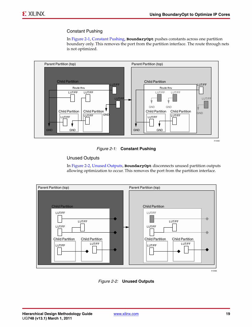
Constant Pushing
In Figure 2-1, Constant Pushing, BoundaryOpt pushes constants across one partition boundary only. This removes the port from the partition interface. The route through nets is not optimized.
Unused Outputs
In Figure 2-2, Unused Outputs, BoundaryOpt disconnects unused partition outputs allowing optimization to occur. This removes the port from the partition interface.
Figure X-Ref Target - Figure 2-1
Figure 2-1: Constant Pushing
Figure X-Ref Target - Figure 2-2
Figure 2-2: Unused Outputs
20 www.xilinx.com Hierarchical Design Methodology GuideUG748 (v13.1) March 1, 2011
Chapter 2: Design Considerations
BoundaryOpt ValuesBoundaryOpt values are:
• all
• none
The value set on a partition is shown in the Partition Summary section of the Map Report.
Architecting the DesignWhen implementing a design using a flat flow, synthesis and implementation tools can optimize the design for speed and area as a whole. Since the tools can optimize across hierarchical boundaries, the logical layout of the design is not as critical.
When implementing a design using an HD flow, partitions act as an optimization barrier in order to isolate the logic. This can dramatically impact the design. See the following figure as an example.
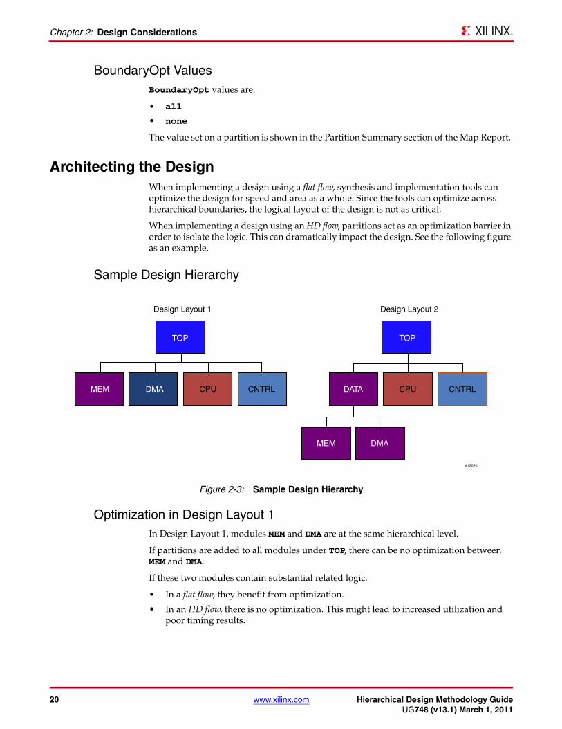
Sample Design Hierarchy
Optimization in Design Layout 1In Design Layout 1, modules MEM and DMA are at the same hierarchical level.
If partitions are added to all modules under TOP, there can be no optimization between MEM and DMA.
If these two modules contain substantial related logic:
• In a flat flow, they benefit from optimization.
• In an HD flow, there is no optimization. This might lead to increased utilization and poor timing results.
Figure X-Ref Target - Figure 2-3
Figure 2-3: Sample Design Hierarchy
Hierarchical Design Methodology Guide www.xilinx.com 21UG748 (v13.1) March 1, 2011
Achieving the Benefits of an HD Flow
Optimization in Design Layout 2In Design Layout 2, modules with shared logic are grouped together under one partition (DATA). The same optimization for MEM and DMA that was not possible in a flat flow can be achieved in an HD flow by redefining the hierarchy.
Achieving the Benefits of an HD FlowDecide whether to use an HD flow before architecting the design, defining module interfaces, and coding the modules. HD flows are not timing closure techniques to be used after timing issues arise in a flat flow.
The partition creates insulation for the module, which limits the ability of the software to optimize across the boundary.
To achieve the benefits of an HD flow:
• Register Input and Output Ports
• Do Not Use Nets Both Inside and Outside a Partition
• Manage High Fanout Nets
• Avoid Constants as Nets
• Avoid Unconnected Ports
• Place Dedicated Connections in the Same Partition
Register Input and Output PortsYou must register inputs and outputs if possible.
Since no optimization occurs across the partition boundary, inputs and outputs can quickly become timing bottlenecks.
Registering the inputs and outputs:
• Enables the tools to focus on paths that are internal to the partition.
• Allows true timing preservation on the module.
Nets that cross a partition boundary are not preserved unless all partitions connected to the net are imported. As a result, timing critical nets that cross this boundary might continue to cause violations in the partition even when imported. Registering the boundary nets prevents timing critical changes internal to the partition.
Do Not Use Nets Both Inside and Outside a PartitionDo not use nets both inside and outside a partition.
If nets must be used both in a partition, and as output ports:
• Duplicate the source of the nets.
• Use one net internally.
• Use the other net as the output port.
22 www.xilinx.com Hierarchical Design Methodology GuideUG748 (v13.1) March 1, 2011
Chapter 2: Design Considerations
Manage High Fanout NetsYou must account for fanout on outputs of partitioned modules. If the output of a partition has a high fanout, and connects to multiple areas of the design, the driver might need to be replicated.
• In flat flows, this replication occurs automatically.
• In HD flows, you must replicate the driver by hand.
Avoid Constants as NetsAvoid constants as nets.
Some netlist modules, such as IP cores, assume that the Map tool will optimize away unneeded portions of logic. This is generally achieved by tying inputs of the core to constants that either enable or disable certain logic.
This technique:
• Allows IP to be delivered as a netlist, while still allowing some customization.
• Does not work well with partitions because of the optimization boundary.
If a partition is added directly to an Electronic Data Interchange Format (EDIF) or Native Generic Circuit (NGC) core for which the Map tool is expected to optimize logic based on constants on the ports, no logic optimization occurs. The results will not be ideal.
If you must place a partition on a core that exhibits this behavior:
• Add an HDL wrapper to wrap the EDIF or NGC core.
• Place the partition on the wrapper.
The port list of the HDL wrapper should contain only the necessary I/O connecting the IP core to the rest of the design. Constant assignments can remain in the wrapper logic. With the partition defined a level above the IP core, the Map tool can trace the constant into the core and perform any necessary optimization.
Avoid Unconnected PortsAvoid unconnected ports.
Unconnected outputs have a similar effect on optimization. If a partition output is unconnected, the Map tool cannot optimize the driver associated with this source-less net as it can in a flat flow.
If this logic cannot be optimized in the HDL code, adding a wrapper around the partition:
• Moves the partition boundary.
• Allows the Map tool to optimize the logic.
A partition output can cause errors if it:
• Is not driven by logic, and
• Connects to logic outside the partition.
The implementation tools cannot see that the partition output is not driven, and route a partial net. This causes Design Rules Check (DRC) errors during the BitGen process. Remove any unnecessary partition ports and re-implement the partition.
Hierarchical Design Methodology Guide www.xilinx.com 23UG748 (v13.1) March 1, 2011
Limitations on Preserving Routing Information
Place Dedicated Connections in the Same PartitionPlace dedicated connections in the same partition.
Some elements in the FPGA device work together to provide specific functions, or to provide dedicated connections for fast, low skew routing.
These elements cannot always be correctly configured if they are separated by a partition boundary. Place these instances in the same partition.
These elements are:
• OSERDES/IODELAY and OBUFTDS
• OSERDES/ODDR and OBUFTDS
• IDELAY and IDELAYCNTRL
• ISERDES/IDDR & IBUFDS
Limitations on Preserving Routing InformationNot all routing information can be preserved.
A route that belongs to a partition might be rerouted when:
• The preservation level of the imported partition is set to Placement or Synthesis instead of Routing.
• An I/O buffer in a lower level partition is imported, and the associated pad is in the parent implemented partition.
Since this route is dedicated, it does not change even though it is not technically preserved.
• A flip-flop in a lower level partition is imported, and is connected to an I/O buffer in the parent implemented partition.
The route is dedicated and remains identical if the flip-flop is packed into the I/O logic. An IOB=FORCE or an IOB=TRUE constraint is necessary to allow the tools to pull the flip-flop across the partition boundary and pack it into the I/O Logic. If the flip-flop is packed into a slice, the routing is not preserved and timing cannot be guaranteed.
If the implementation tools cannot properly pack the flip-flop into the I/O logic:
• IOB=FORCE generates an error.
• IOB=TRUE generates a warning.
• A LUT in a lower level partition is imported, and is connected to an I/O buffer in the parent implemented partition. In this instance:
• The LUT must be packed into slice logic.
• The route is not dedicated.
• Timing cannot be guaranteed
• A PWR/GND net exists in the design, and the top partition is implemented.
PWR/GND nets are always implemented or imported along with the top partition, even if the nets belong to a child partition.
24 www.xilinx.com Hierarchical Design Methodology GuideUG748 (v13.1) March 1, 2011
Chapter 2: Design Considerations
Floorplanning PartitionsNote: This section specifically refers to using AREA_GROUP constraints.
Floorplanning means controlling the placement of a design through constraints.
Creating Slice Ranges on a CLB BoundaryAlthough there are no restrictions on using AREA_GROUP constraints in partitioned designs, Xilinx recommends creating slice ranges on a CLB boundary. Doing so maximizes the available resources for placement and routing.
To verify that a slice range was correctly aligned to a CLB boundary, check the XY coordinates of the constraint.
The range is on a CLB boundary if the XY coordinates:
• Start on an even number.
• End on an odd number.
Example: X0Y0 to X3Y9
You can use the PlanAhead™ software to:
• Create the AREA_GROUP constraints.
• Snap the constraints to CLB boundaries.
For more information on CLBs and other blocks in the FPGA device, see the Xilinx Data Sheets cited in Appendix A, Additional Resources.
Keeping Logic in One Area of the DeviceFloorplanning keeps all logic associated with a partition in one area of the device.
Keeping logic in one area of the device:
• Creates a region for placing and routing each partition.
• Minimizes the risk of routing conflicts during import.
• Reserves other parts of the FPGA device for additional logic that will be included later.
Using the Command Line ToolsAlthough the PlanAhead software supports partitions, you can also run the partitioned design using the command line tools.
You can use the PlanAhead software to:
• Set up the partitions.
• Floorplan the design.
• Create the PXML file.
For more information, see:
• Chapter 4, Command Line Partition Flows

Hierarchical Design Methodology Guide www.xilinx.com 25UG748 (v13.1) March 1, 2011
Floorplanning Partitions
Design PreservationWhile design preservation partitions do not require an AREA_GROUP constraint, floorplanning some designs with AREA_GROUP can:
• Improve runtime and timing results.
• Reduce placement and routing conflicts during import.
Team Design Flow Requirements• Each Team Member partition must have an associated ranged AREA_GROUP
constraint to contain the required logic for that partition.
If the logic from a Team Member partition must be located outside the AREA_GROUP RANGE, move that logic to the top-level partition to avoid placement conflicts during assembly.
• No Team Member AREA_GROUP RANGE is allowed to overlap with any other Team Member AREA_GROUP RANGE.
This includes AREA_GROUP RANGE constraints belonging to the top partition.
• Each Team Member partition must belong to:
• A single AREA_GROUP, or
• A child of that AREA_GROUP.
• Do not group logic from one Team Member with logic from another Team Member in an AREA_GROUP constraint. Relocate any logic critical to the interface timing between the two Team Member partitions to the top partition. This allows the logic to be placed across both Team Member partitions.

26 www.xilinx.com Hierarchical Design Methodology GuideUG748 (v13.1) March 1, 2011
Chapter 2: Design Considerations
Hierarchical Design Methodology Guide www.xilinx.com 27UG748 (v13.1) March 1, 2011
Synthesis Flows
Chapter 3
Synthesis Partition Flows
This chapter discusses synthesis partition flows, and includes:
• Synthesis Flows
• Synthesis Tools
Synthesis FlowsIn a Hierarchical Design (HD) flow, each partition is synthesized individually. Individual synthesis prevents a design change in one area from causing different synthesis results in another area.
The available flows are:
• Incremental Synthesis Flow
• Bottom-Up Synthesis Flow
Incremental Synthesis FlowMost third-party synthesis tools support incremental synthesis.
During incremental synthesis:
• Register Transfer Level (RTL) modules can be marked as partitions.
• Each partition is synthesized separately with hard hierarchical boundaries.
• A Hardware Design Language (HDL) change in one module does not affect another module.
• The tools determine which modules or instances must be re-synthesized because of HDL or constraint changes.
Supported Incremental Synthesis Flows
The supported incremental synthesis flows are:
• Synplify Pro and Synplify Premier
Uses compile points.
• Mentor Precision
Uses attributes in HDL to specify partitions.

28 www.xilinx.com Hierarchical Design Methodology GuideUG748 (v13.1) March 1, 2011
Chapter 3: Synthesis Partition Flows
Advantages of Incremental Synthesis Flow
The incremental synthesis flow has the following advantages:
• No need to create separate synthesis project files for each partition.
• An easier transition from a flat synthesis flow.
• The synthesis tool determines which modules are re-synthesized because of HDL code changes and timing constraint changes.
Bottom-Up Synthesis FlowIn the bottom-up synthesis flow:
• Each partition has a separate synthesis project and resulting netlist.
• The designer decides which synthesis projects to run because of HDL code or synthesis constraint changes.
• The top-level is synthesized by using black boxes for the lower-level modules.
• The lower-level modules are synthesized without inferring I/O or clock buffers.
Supported Bottom-Up Synthesis Flows
The bottom-up synthesis flow is supported by:
• Third-party synthesis tools
• Xilinx Synthesis Technology (XST)
Uses attributes in HDL to specify partitions.
Advantages of Bottom-Up Synthesis Flows
The bottom-up synthesis flow has the following advantages:
• Each Team Member has their own synthesis project.
Several Team Members can work on the same overall design during synthesis.
• Team Members have complete control over which instances are re-synthesized.
• The Team Member determines which project is re-synthesized, making it easier to determine which instances are re-synthesized.
• Each netlist has a unique time stamp.

Hierarchical Design Methodology Guide www.xilinx.com 29UG748 (v13.1) March 1, 2011
Synthesis Tools
Synthesis ToolsSynthesis tools include:
• Synplify Pro and Synplify Premier
• Mentor Precision
• Xilinx Synthesis Technology (XST)
Synplify Pro and Synplify PremierThere are two ways to use Synplify Pro and Synplify Premier for partitions:
• Synplify Pro and Synplify Premier Bottom-Up Synthesis Flow
• Synplify Pro and Synplify Premier Incremental Synthesis Flow
Synplify Pro and Synplify Premier Bottom-Up Synthesis Flow
In the Synplify Pro and Synplify Premier bottom-up flow, each instance has a corresponding Synplify project file. Do not infer IOBs or global clock buffers in the lower-level project files.
• To turn off I/O insertion in the project file, use the following:
set_option disable_io_insertion 1
• To use syn_noclockbuf to automatically turn off clock buffer usage:
• Insert the following in the Synplify Design Constraints (SDC) file:
define_attribute { clock_port } syn_noclockbuf 0define_global_attribute syn_noclockbuf 0
OR
• Insert syn_noclockbuf directly into the HDL code.
For more information, see the Synplify documentation.
Synplify Pro and Synplify Premier Incremental Synthesis Flow
Synplify Pro and Synplify Premier support the incremental synthesis flow. The incremental synthesis flow uses compile points to break down the design into smaller synthesis units.
Use the locked mode to create a solid boundary with no logic moving in or out of the compile point. The soft and hard modes allow optimizations across boundaries, which are not supported. Any netlist changes to a partition require that a partition be implemented. The NGDBuild tool issues an error if the netlist does not match the imported partition.
Following is an example compile point in the SDC file:
define_compile_point {v:controller} -type {locked} -cpfile {}

30 www.xilinx.com Hierarchical Design Methodology GuideUG748 (v13.1) March 1, 2011
Chapter 3: Synthesis Partition Flows
Synplify Synthesis Report
Use Synplify to create and modify any compile points in the SDC file. The Synthesis Report displays the status of each compile point.
Summary of Compile PointsName Status Reason-------------------------------------------------controller Unchanged -elevator_car Remapped Design changedexpress_car Remapped Design changedtop Remapped Design changed=================================================
Running the Xilinx Implementation Tools (Synplify)
After synthesis, you can use any of the following to run the Xilinx® implementation tools:
• ISE® Design Suite Command Line Flow (Synplify)
• PlanAhead Software Flow (Synplify)
• Synplify Cockpit (Synplify)
ISE® Design Suite Command Line Flow (Synplify)
Synplify runs a Tcl command to create an updated PXML file for use with the Xilinx implementation tools.
For more information, see:
• Chapter 4, Command Line Partition Flows
PlanAhead Software Flow (Synplify)
The PlanAhead™ software flow imports:
• The synthesis netlists
• The PXML file generated from Synplify (optional)
You can also redefine the partitions manually inside the PlanAhead software.
For more information, see:
• Chapter 5, PlanAhead Partition Flows
Synplify Cockpit (Synplify)
Run the Xilinx implementation tools from within the Synplify cockpit.
For more information, see the Synplify Pro and Synplify Premier documentation available at:
• http://www.synopsys.com
Hierarchical Design Methodology Guide www.xilinx.com 31UG748 (v13.1) March 1, 2011
Synthesis Tools
Mentor PrecisionThe Mentor Precision synthesis tool supports HD flows. The most common flow is the partitions-based incremental flow. In this flow, you can specify partitions using attributes. These can be set on a module or instance.
Precision Synthesis Report
Verilog Module:module my_block( input clk; ...) /* synthesis incr_partition */;Verilog Instance:my_block my_block_inst( .clk(clk), ... .data_out(data_out) ); // synthesis attribute my_block_instincr_partition trueVHDL Module:entity my_block is port( clk: in std_logic; ...); attribute incr_partition : boolean; attribute incr_partitionof my_block : entity is true; end entity my_block;VHDL Instance:component my_block is port( ... end component; ... attribute incr_partition : boolean; attributeincr_partition of my_block_inst : label is true; ... my_block_inst
The Synthesis Report shows whether or not a partition is being optimized based on the partition state.
[16027]: Incremental: Skipping Optimize for <...>.fifo_16_64.rtl_unfold_0[16027]: Incremental: Skipping Optimize for <...>.fir_filter.rtl_unfold_0[15002]: Optimizing design <...>.fsm.rtl_unfold_0[16027]: Incremental: Skipping Optimize for <...>.fir_top.rtl
Running the Xilinx Implementation Tools (Precision)
After synthesis, you can use any of the following to run the Xilinx® implementation tools:
• ISE Design Suite Command Line Flow (Precision)
• PlanAhead Software Flow (Precision)
• Mentor Precision (Precision)
ISE Design Suite Command Line Flow (Precision)
Click Place & Route to create a PXML file for use with the Xilinx implementation tools.
For more information, see:
• Chapter 4, Command Line Partition Flows
PlanAhead Software Flow (Precision)
The PlanAhead software flow imports the synthesis netlists. The design partitions are defined inside the PlanAhead software.
For more information, see:
• Chapter 5, PlanAhead Partition Flows

32 www.xilinx.com Hierarchical Design Methodology GuideUG748 (v13.1) March 1, 2011
Chapter 3: Synthesis Partition Flows
Mentor Precision (Precision)
Click Place & Route to run the ISE Design Suite implementation tools automatically.
For more information, see the application note on the Mentor Graphics SupportNet site at http://supportnet.mentor.com
Xilinx Synthesis Technology (XST)The Xilinx Synthesis Technology (XST) supports:
• XST Bottom-Up Synthesis Flow
• XST Top-Down Incremental Flow
XST Bottom-Up Synthesis Flow
Each instance used as a partition (including the top partition) has its own synthesis project file.
Caution! Do not infer IOBs or global clock buffers in lower-level partitions if they are contained in the top partition.
Use the following option in the XST file to prevent IOs from being inferred:
-iobuf NO
If IOBs are used in a lower-level partition, you must prevent an additional IOB from being inferred in the top-level. To turn off IOB insertion:
• For the entire top-level, use the –iobuf option.
• For individual signals, put a BUFFER_TYPE=NONE attribute on the individual signal names.
The BUFFER_TYPE=NONE attribute can also be used to prevent global buffers (BUFG) from being inferred in the top-level when a lower-level partition has a BUFG instantiated.
For more information on how to set the BUFFER_TYPE attribute, and how to run XST in command line mode, see:
• XST User Guide for Virtex®-4, Virtex-5, Spartan®-3, and Newer CPLD Devices (UG627), cited in Appendix A, Additional Resources
• XST User Guide for Virtex-6, Spartan-6, and 7 Series Devices (UG687), cited in Appendix A, Additional Resources
XST Top-Down Incremental Flow
The XST top-down incremental flow:
• Is new in the ISE Design Suite 13.1 release.
• Allows easier setup than bottom-up flow.
• Supports both the command line and the PlanAhead software.
• Allows you to define partitions on hierarchical instances. XST writes out individual Native Generic Circuite (NGC) files for each partition.
The partitions are defined and controlled by a PXML file named xpartition.pxml.
• For the command line, the PXML file can be the same or a different PXML file than the PXML file used for implementation.
• The PlanAhead software manages the PXML files.
Hierarchical Design Methodology Guide www.xilinx.com 33UG748 (v13.1) March 1, 2011
Synthesis Tools
For more information on using this capability for a particular methodology such as Design Preservation or Team Design, see the other chapters of this document.
XST reads a PXML file as follows:
• If the PXML file exists in the current working directory, XST automatically reads it in.
• If the PXML file exists in a different directory (such as an implementation directory), use the -partition_file switch to point XST to the file.
This switch can specify one or more remote locations to search for a PXML file.
Since the XST incremental flow supports importing unchanged partitions, some partitions might be set to Import and have an ImportLocation attribute defined. If the ImportLocation is a relative path, the path must be relative to the PXML file, not relative to the present working directory, if different.
A partition set to import in synthesis might need to be set to implement for implementation if the exported implementation data:
• Is out-of-date, or
• Does not exist.
In this case, it might be easier to use separate PXML files for synthesis and implementation.
In order to import previous synthesis results, the results must be exported to another location. This prevents the results from being overwritten in the next synthesis run. The exported synthesis results must contain the NGC and HDX files for the partition that is being imported.
34 www.xilinx.com Hierarchical Design Methodology GuideUG748 (v13.1) March 1, 2011
Chapter 3: Synthesis Partition Flows

Hierarchical Design Methodology Guide www.xilinx.com 35UG748 (v13.1) March 1, 2011
Creating a PXML File
Chapter 4
Command Line Partition Flows
The ISE® Design Suite command line partition flow:
• Uses partitions on a post-synthesis design.
• Is command-line driven.
• Uses the Xilinx® implementation tools:
• NGDBuild
• Map
• PAR
The Xilinx implementation tools:
• Automatically look for the PXML file in the current working directory.
The current working directory is the directory from which the implementation tools are being run.
• Use the PXML file to determine:
• The partitions defined in the design
• The partition states
Creating a PXML FileThe PXML file:
• Contains partition definitions.
• Is case-sensitive.
• Must be named xpartition.pxml.
• Must be consistently present for all implementation tools:
• NGDBuild
• Map
• PAR
• Can be created:
• Manually in a text editor.
A template for manually creating a PXML file is located in the install directory at:
<Xilinx_13_directory>/PlanAhead/testcases/xpartition.pxml
• In a software tool, such as the PlanAhead™ software.
To use the PlanAhead software to create a PXML file, see:
• Exporting PXML Files in Chapter 5, PlanAhead Partition Flows

36 www.xilinx.com Hierarchical Design Methodology GuideUG748 (v13.1) March 1, 2011
Chapter 4: Command Line Partition Flows
If you create the PXML file by hand, or with a third-party synthesis tool, see:
• Running Implementation
The top-level module of the design must be defined as a partition in addition to any optional lower-level partitions. Child or nested partitions are supported.
The implementation tools automatically recognize the PXML file when it is located in the current working directory.
Sample PXML File<?xml version="1.0" encoding="UTF-8" ?>
<Project FileVersion="1.2" Name="Example" ProjectVersion="2.0"> <Partition Name="/top" State="implement" ImportLocation="NONE"> <Partition Name="/top/module_A" State="import" ImportLocation="/home/user/Example/export" Preserve="routing"> </Partition> <Partition Name="/top/module_B" State="import" ImportLocation="../export" Preserve="routing"> </Partition> <Partition Name="/top/module_C" State="implement" ImportLocation="../export" Preserve="placement"> </Partition> </Partition></Project>
PXML Attributes and ValuesThe following tables describe the attributes and values used in the sample PXML file.
Table 4-1: PXML Attribute and Values for Project Definition
Attribute Name Value Description
FileVersion 1.2 Used for internal purposes. Do not change this value
Name Project_Name Project_Name is user defined.
ProjectVersion 2.0 Used for internal purposes. Do not change this value
Table 4-2: PXML Attributes and Values for Partition Definition
Attribute Name Value Description
Name Partition_Name Hierarchical instance name of module in which the partition should be applied.
State implement Partition is implemented from scratch.
import Partition is imported and preserved according to the level set by Preserve.

Hierarchical Design Methodology Guide www.xilinx.com 37UG748 (v13.1) March 1, 2011
Creating a PXML File
ImportLocation Path Ignored if State does not equal import. Path can be relative or absolute, but the location specified must contain a valid export directory when State=import. NONE is a predefined keyword for no import directory.
ImportTag Partition_Name Allows a partition to be imported into a different level of hierarchy than it was initially implemented in. Set the value to the hierarchical instance name of the partition when it was implemented.
Preserve routing 100% placement and routing is preserved. This is the default for top-level partition.
placement Placement is preserved, and routing can be modified.
synthesis Placement and routing can be modified.
inherit Inherit value from the parent partition. This is the default for all partitions except the top-level partition.
BoundaryOpt all Enables the implementation tools to do optimization on partition ports connected to constants as well as unused partition ports.
none Normal partition optimization rules apply. Optimization allowed only within partition boundary. This is the default value.
Table 4-2: PXML Attributes and Values for Partition Definition (Cont’d)
Attribute Name Value Description

38 www.xilinx.com Hierarchical Design Methodology GuideUG748 (v13.1) March 1, 2011
Chapter 4: Command Line Partition Flows
Running ImplementationOnce the PXML file has been created, you can run the Xilinx implementation tools in command line mode or batch mode.
Following is a sample basic script:
ngdbuild -uc design.ucf design.edn design.ngdmap -w design.ngd -o design_map.ncd design.pcfpar -w design_map.ncd design.ncd design.pcf
The netlist specified in the NGDBuild command must not be the output of a flat synthesis run. The synthesis project must be created with partitions in mind when it is set up and run.
For more information, see:
• Chapter 3, Synthesis Partition Flows
Implementation Tool ReportsReview the implementation tool reports to verify that:
• The tools recognized the PXML file.
• The partition states are set correctly.
For example, the NGDBuild Report (.bld) contains a section displaying the partition implementation status. The Map Report and the PAR Report contain similar sections.
-------------------------------Partition Implementation Status-------------------------------Preserved Partitions:
Implemented Partitions: Partition "/top": Attribute STATE set to IMPLEMENT.
Partition "/top/Control_Module": Attribute STATE set to IMPLEMENT.
Partition "/top/Express_Car": Attribute STATE set to IMPLEMENT.
Partition "/top/Main_Car": Attribute STATE set to IMPLEMENT.
Partition "/top/Tracking_Module":
Implementation Options Not Supported By PartitionsPartitions do not support the following implementation options:
• Global Optimization (-global_opt)
• SmartGuide™ technology (-smartguide)
• Power Optimization (-power)
• Multithreading (-mt)
Hierarchical Design Methodology Guide www.xilinx.com 39UG748 (v13.1) March 1, 2011
Exporting Partitions
Many special Xilinx environment variables (XIL_*) can significantly impact the implementation tools. These effects might vary from one ISE Design Suite release to the next. Since Xilinx HD flows have not been tested with environment variables, Xilinx recommends removing all special Xilinx environment variables before running the tools.
Exporting PartitionsExport the partitions when you are satisfied with the implementation results. To export partitions, copy the implementation files to an export directory.
If a complete copy of the implementation directory is too large, use a script to copy only:
• Required Files
• Optional Files
Required FilesThe required files are:
• The *prev*.* files
The *prev*.* files contain the previous implementation data required to import a partition.
• The PXML file
The PXML file must be included in order to verify that it is appropriate to import a partition. For example, if the PXML file does not contain the partition being imported, the PlanAhead software generates an error.
Optional FilesThe optional files are:
• The report files from:
• NGDBuild (.bld)
• Map (.mrp and .map)
• PAR (.par)
• TRACE (.twr/.twx)
• The User Constraint File (UCF)
These files are optional, but important. They document the options that were run when the design was implemented.
Caution! Do not to modify the files in the exported directory in any way. They become source-like files.
Multiple partitions in a design are all exported. Think of the entire design as being exported, rather than a specific partition.
For faster runtime, create one directory with all exported data. This limits the number of design files loaded into memory when the partitions are imported.

40 www.xilinx.com Hierarchical Design Methodology GuideUG748 (v13.1) March 1, 2011
Chapter 4: Command Line Partition Flows
Updating Partition State to ImportOnce the partition has been exported, update the PXML file to reflect the current state of the partitions. Use a text editor.
To import a partition that has been exported:
1. Set the partition state to import.
2. Set the ImportLocation attribute to the location of the exported partitions.
You can specify:
• A relative path, such as:
../export
• An absolute path, such as:
/home/user/Example/export
Iterative DesignMake any necessary design changes and re-synthesize. If synthesis modifies an exported partition, manually change the partition state from import to implement in the PXML file.
The NGDBuild tool issues an error if you attempt to import a partition that does not exactly match the partition from the import location.
ERROR:NgdBuild:1037 - The logic for imported partition '/top/Main_Car' using previous implementation './export/top_prev_built.ngd' has been modified.
A failure can occur if the partition source was modified, but the partition was not re-implemented and exported. The partition must be re-implemented and exported before it can be imported into the design.
Adding comments to the Hardware Design Language (HDL) code might result in small logic or naming changes in the netlist. The partition must be implemented on the next iteration.
If a partition is imported with the preservation level set to anything other than routing, and the placement and routing are modified by the PAR tool, the partition must be exported in order to be used in the next iteration.
Using SmartXplorer in Partitioned DesignsUse SmartXplorer to help meet timing in partitioned designs with tight timing requirements:
1. Run SmartXplorer on the completed partitioned portions of the design.
2. Use the standard implementation flow to implement other portions of the design that are changing.
3. Import the SmartXplorer results for the timing critical modules.
For more information on SmartXplorer, see the Command Line Tools User Guide (UG688), cited in Appendix A, Additional Resources.
Hierarchical Design Methodology Guide www.xilinx.com 41UG748 (v13.1) March 1, 2011
Removing and Restoring Partitions
SmartXplorer Directory PathsWhen importing partitions from a SmartXplorer run, the import location in the PXML file must point to the directories created by SmartXplorer.
The directory path can be:
• Relative, such as:
../run2
• Absolute, such as:
/home/user/Example/run2
SmartXplorer InputsYou can run SmartXplorer with either the top-level netlist or the Native Generic Database (NGD) file as the input.
If the input is an NGD file:
• The NGD file must be created using the same PXML file used by the Map tool and the PAR tool.
If no PXML file was present when the NGDBuild tool was run, the Map tool and the PAR tool ignore the PXML file.
• SmartXplorer runs the Map tool and the PAR tool. The NGD file is one level up.
To import the SmartXplorer results, the *prev_built.ngd file one level up must be copied into the appropriate runs directory created by SmartXplorer before importing from that location.
Removing and Restoring PartitionsYou can remove and restore partitions.
Removing Individual PartitionsTo remove individual partitions:
1. Remove the references from the PXML file.
2. Set the state of the parent partition to implement.
Removing All PartitionsTo remove all partitions and run a flat flow:
1. Rename or remove the PXML file from the implementation directory.
Restoring PartitionsTo restore partitions:
1. Add the PXML file back to the implementation directory, or
2. Add individual lines back to the PXML file defining the partitions.
42 www.xilinx.com Hierarchical Design Methodology GuideUG748 (v13.1) March 1, 2011
Chapter 4: Command Line Partition Flows
Partitions that were removed and then added back in might still be able to be imported.
You can import the partitions only if:
• The input netlists have not been changed.
• The export directory still exists.
Hierarchical Design Methodology Guide www.xilinx.com 43UG748 (v13.1) March 1, 2011
Creating a New Project
Chapter 5
PlanAhead Partition Flows
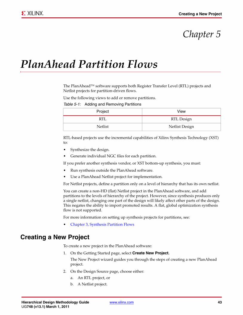
The PlanAhead™ software supports both Register Transfer Level (RTL) projects and Netlist projects for partition-driven flows.
Use the following views to add or remove partitions.
RTL-based projects use the incremental capabilities of Xilinx Synthesis Technology (XST) to:
• Synthesize the design.
• Generate individual NGC files for each partition.
If you prefer another synthesis vendor, or XST bottom-up synthesis, you must:
• Run synthesis outside the PlanAhead software.
• Use a PlanAhead Netlist project for implementation.
For Netlist projects, define a partition only on a level of hierarchy that has its own netlist.
You can create a non-HD (flat) Netlist project in the PlanAhead software, and add partitions to the levels of hierarchy of the project. However, since synthesis produces only a single netlist, changing one part of the design will likely affect other parts of the design. This negates the ability to import promoted results. A flat, global optimization synthesis flow is not supported.
For more information on setting up synthesis projects for partitions, see:
• Chapter 3, Synthesis Partition Flows
Creating a New ProjectTo create a new project in the PlanAhead software:
1. On the Getting Started page, select Create New Project.
The New Project wizard guides you through the steps of creating a new PlanAhead project.
2. On the Design Source page, choose either:
a. An RTL project, or
b. A Netlist project.
Table 5-1: Adding and Removing Partitions
Project View
RTL RTL Design
Netlist Netlist Design

44 www.xilinx.com Hierarchical Design Methodology GuideUG748 (v13.1) March 1, 2011
Chapter 5: PlanAhead Partition Flows
3. Continue through the wizard.
4. Specify the following:
a. Sources
b. User Constraint Files (UCF)
5. Click Finish.
Creating PartitionsTo create partitions in the PlanAhead software:
1. Load the RTL Design view or the Netlist Design view in the Flow Navigator.
2. Select the RTL Netlist tab or the Netlist tab to view the design hierarchy.
3. Select the module instances to be partitioned.
4. Right-click and select Set Partition.
Select only instances that have been designed and synthesized with partitions in mind.
Importing PXML FilesSynplify can generate a PXML file in the Synplify compile points flow.
For more information, see the Synplify documentation relating to sxml2pxml.
The values in the sxml2pxml file can be imported into the PlanAhead software to define the partitions for you. If any partitions are already defined, the option is grayed out.
To import a PXML file:
1. Load the RTL Design view or the Netlist Design view in the Flow Navigator.
2. Select the Netlist tab to view the design hierarchy.
3. In the Netlist window, right-click and select Import Partition Settings.
Exporting PXML FilesYou can use the PlanAhead software to create a PXML file for use in the ISE® Design Suite command line flow.
Note: The following example is for a Netlist project, but the same method can be used for RTL projects from either the RTL Design view (pre-synthesis) or from the Netlist Design view (post-synthesis).
To create a PXML file:
1. Load the RTL Design view or the Netlist Design view in the Flow Navigator.
2. Click the Netlist tab.
3. Select the module instances to be marked as partitions.
4. Right-click and select Set Partition.
5. From the Synthesize button or the Implement button pull-down list, select Implementation Settings.
The Implementation Settings dialog box opens.
6. Click the button next to current launch options.
The Launch Options dialog box opens.
Hierarchical Design Methodology Guide www.xilinx.com 45UG748 (v13.1) March 1, 2011
Setting the BoundaryOpt Attribute
7. Select Generate scripts only.
8. Click OK.
9. Click Run.
The PXML file:
• Is generated in the <project_name>.runs/impl_1 directory.
• Can be copied to the location from which the ISE Design Suite command line flow is run.
For more information on running HD flows, see:
• PlanAhead Flow in Chapter 6, Design Preservation Flows
For more information on how to use the PlanAhead software, see the PlanAhead User Guide (UG632) cited in Appendix A, Additional Resources.
Setting the BoundaryOpt AttributeThe BoundaryOpt attribute enables some optimization on a partition boundary. This optimization affects implementation results only. There is no XST support.
To add the BoundaryOpt attribute on a partition:
1. Select the partition in the Netlist view.
2. In the Instance Properties view, select the Partition tab.
3. Check the Boundary Optimization box.
4. Click Apply.
For more information, see:
• Chapter 2, Design Considerations
Setting the ImportTag AttributeThe ImportTag attribute allows a partition defined in one hierarchy to be imported into a new hierarchy. This is supported for:
• The XST incremental flow
• The implementation tools
To add the ImportTag attribute on a partition:
1. Open the Tcl Console.
2. Enter the following Tcl command:
set_property ImportTag "<original_partition_name>" [get_cells"<current_partition_name>"]
To remove the ImportTag attribute, repeat this command, but leave the value empty:
set_property ImportTag "" [get_cells "<current_partition_name>"]
For more information, see:
• Chapter 1, Partitions
46 www.xilinx.com Hierarchical Design Methodology GuideUG748 (v13.1) March 1, 2011
Chapter 5: PlanAhead Partition Flows
Floorplanning PartitionsTo decide if a partition should be floorplanned, see:
• Deciding When to Use Partitions
By selecting the partitions in the Netlist tab one at a time, you can create a Pblock for each partition. A Pblock in the PlanAhead software defines the AREA_GROUP constraints.
To create a Pblock:
1. Right-click a partition instance.
2. Select Draw Pblock.
3. In the Device view, draw a rectangular area into which the partition will be placed.
For more information on how to floorplan modules in the PlanAhead software, see Design Analysis and Floorplanning (UG676) cited in Appendix A, Additional Resources.
Synthesizing a Partitioned DesignTo synthesize a partition-based design:
1. Create an RTL project.
2. Define partitions using the RTL Design view.
3. Click Synthesize.
This procedure runs XST with default options using the incremental technology. XST generates an individual Native Generic Circuite (NGC) file for each partitioned instance.
To modify the synthesis options before the run:
1. Click Synthesize.
2. Select Synthesis Settings.
3. Make your changes.
Implementing a Partitioned DesignTo implement a partition-based design, follow the steps in the following sections for:
• Novice Users
• Advanced Users
Novice UsersThis section applies to:
• Novice users.
• Users interested in minimal setup requirements.
To implement a partition-based design:
1. Click Implement.
2. The implementation tools run using the default strategy.

Hierarchical Design Methodology Guide www.xilinx.com 47UG748 (v13.1) March 1, 2011
Promoting Partitions
The default strategy is usually the ISE Design Suite default settings for the following tools:
• NGDBuild
• Map
• PAR
• TRACE
To modify the implementation options before the run:
1. Click Implement.
2. Select Implementation Settings.
3. Make your changes.
Advanced UsersThis section applies to advanced users.
To implement a partition-based design:
1. Click Implement.
2. Select Create Multiple Runs.
This option:
• Can be used to create multiple implementations with varying implementation options.
• Is similar to running SmartXplorer in the command line.
The results of the implementation can be monitored:
• In the Compilation Log window, or
• From the status bar, or
• By selecting Window > Design Runs
Once the implementation has completed:
1. Click Implemented Design to load the results.
2. View the implementation report files to verify that the partitions were properly defined and used by the implementation tools.
Promoting PartitionsWhen a partition has been successfully synthesized or implemented, it must be promoted for future import runs. Promoting a partition in the PlanAhead software is the same as exporting a partition in the command line flow.
To promote partitions from the active run, click Promote Partitions.
Failing to promote a run loses the current partition results if the run is reset.
Once the results are promoted, you can reset the current run, and rerun it as many times as necessary. The promoted results are imported as long as the partition has not changed. Promoting new results overwrites the current promoted data for a particular run.

48 www.xilinx.com Hierarchical Design Methodology GuideUG748 (v13.1) March 1, 2011
Chapter 5: PlanAhead Partition Flows
For more information on managing multiple runs and promoted data, see Leveraging Design Preservation for Predictable Results (UG747) cited in Appendix A, Additional Resources.
Managing Partition AttributesYou can modify the following partition attributes:
• Action
Defines the value of the state of the partition (implement or import) that tells the tools to either:
• Synthesize or implement the partition, or
• Import it from a previous run.
• Import From
Defines the location of the run to import a partition from. If Action is set to implement, this value is set to N/A.
• Preservation
Defines the preservation level to be used by the tools when importing a partition. The values are:
• Routing (default)
• Placement
• Synthesis
Managing the Action and Import From Fields When a partition is promoted, the PlanAhead software automatically:
• Sets Action to import.
• Sets Import From to the location selected during the last promote.
Turning Off Automatic Management
To turn off automatic management, deselect Automatically manage Partition action and import location in the Promote Partitions dialog box.
Out-of-Date Runs
The PlanAhead software does not automatically revert the Action field back to implement if the promoted run for a partition is out-of-date.
A promoted run becomes out-of-date when:
• A source file (HDL or Netlist) is updated, or
• A physical constraint associated with a partition has changed.
This affects promoted implementation data only, not promoted synthesis data.
When the run is out-of-date, the source does not match the promoted data, generating an NGDBuild error.
ERROR:NgdBuild:1037 - The logic for imported Partition '/top/Express_Car'

Hierarchical Design Methodology Guide www.xilinx.com 49UG748 (v13.1) March 1, 2011
Managing Design Runs
using previous implementation '../../project_1.promote/Ximpl_1/top_prev_built.ngd' has been modified. This situation can occur when the source for the Partition was modified but the Partition was not re-implemented and exported. You must re-implement and export the Partition before it can be imported into this design.
Managing the Preservation AttributeThe PlanAhead software does not manage the Preservation attribute. You must manage the Preservation attribute manually.
1. From the Implement pull-down menu, select Implementation Settings.
2. Change the Preservation attributes in the Specify Partitions dialog box.
Partition attribute values for synthesis and implementation are independent of each other. In some cases, attribute values must be updated in both locations.
Managing Design RunsThe design can be re-implemented when:
• The design changes have been made.
• Partition states have been set correctly.
Recommended Flow
The recommended flow for design preservation is:
1. Maintain a single design run (impl_1).
2. Promote and re-implement as necessary.
Re-Implementing the Design
After promoting a successful implementation, click Implement to re-implement the design.
Re-implementing the design:
• Resets the run data.
• Launches the implementation tools.
• Imports partitions as defined by the Partition settings.
Promoting the Results
Once the implementation has completed, the results can be promoted. Previously promoted results are overwritten. As a result, only one promote directory exists for the design partitions.
It is sometimes advantageous to have multiple promote locations, or to import partitions from multiple locations. In these cases, you must manage, promote, and import locations to ensure correct results.

50 www.xilinx.com Hierarchical Design Methodology GuideUG748 (v13.1) March 1, 2011
Chapter 5: PlanAhead Partition Flows

Hierarchical Design Methodology Guide www.xilinx.com 51UG748 (v13.1) March 1, 2011
Implementation Runtime
Chapter 6
Design Preservation Flows
Design preservation:
• Reduces the number of implementation iterations during timing closure.
Once a portion of the design meets timing, the implementation results (placement and routing) are used in the next iteration.
• Prevents portions of the design that are complete, and that meet timing, from being affected by changes in other parts of the design.
• Uses partitions to preserve the previous implementation results for a module instance.
Using partitions carefully:
• Reduces the number of design iterations.
• Shortens timing closure.
• Eliminates re-verification of unchanged instances.
Implementation RuntimePreserving portions of the design can affect implementation runtime, depending on:
• Which modules are being implemented, and
• Which modules are being preserved.
Runtime can be longer if the implemented module has extremely tight timing requirements.
Runtime can be shorter if:
• The implemented module easily meets timing, and
• The critical paths are in the preserved modules.

52 www.xilinx.com Hierarchical Design Methodology GuideUG748 (v13.1) March 1, 2011
Chapter 6: Design Preservation Flows
Command Line FlowThis section discusses the command line flow, and includes:
• User Management
• Design Preservation Flow
User ManagementWhen you run the design preservation flow from the command line, you are responsible for managing:
• Which modules have been updated, and
• Which partitions must be implemented instead of imported.
Follow these guidelines:
• Edit the PXML file in a text or XML editor.
• No special implementation options are necessary to invoke the flow.
• The PXML file must reside in the directory in which the implementation is run.
For more information on creating and managing the PXML file, see:
• Chapter 4, Command Line Partition Flows
Design Preservation FlowThe expected progression through a design preservation flow is:
1. A design architect partitions the design early in the design cycle.
2. The design is initially coded.
3. The design is synthesized using an incremental or bottom-up synthesis flow.
For more information on supported synthesis tools and flows, see:
• Chapter 3, Synthesis Partition Flows
4. The design is implemented with a PXML file in which all partitions are set to implement.
5. Once timing has been met on one or more partitions, the results are exported for future iterations.
6. As the design is modified for bug fixes and feature enhancements, modified partitions are re-implemented.
7. Partitions unchanged at the netlist level can be imported to maintain identical placement and routing information.
8. The NGDBuild tool issues an error if the netlist for a partition being imported does not match the design specified in the import location. You must change the partition state to implement.
9. When a partitioned module has been completed with successful timing and verification results, it can continue to be imported as changes to other parts of the design are made.

Hierarchical Design Methodology Guide www.xilinx.com 53UG748 (v13.1) March 1, 2011
PlanAhead Flow
PlanAhead FlowThis section describes how to use the PlanAhead™ software for design preservation. The design preservation flow is a partition-based flow.
For more information, see:
• Chapter 5, PlanAhead Partition Flows
• Leveraging Design Preservation for Predictable Results (UG747) cited in Appendix A, Additional Resources.
The following steps outline the PlanAhead design preservation flow.
1. Create a new Register Transfer Level (RTL) PlanAhead project in the RTL flow to add all existing:
• RTL code
• User Constraint Files (UCF)
2. Open the RTL Design View to elaborate the RTL design.
3. Define partitions by:
• Using the PlanAhead software, or
• Importing an existing PXML file.
4. Synthesize the design in the PlanAhead software with all partition states set to implement.
This increases the incremental capability of Xilinx Synthesis Technology (XST) to generate individual Native Generic Circuite (NGC) files for each partition.
5. Create any necessary constraints, such as:
• Timing constraints, for example:
- PERIOD
- OFFSET IN/OUT
• Floorplanning constraints, for example:
- I/O pin LOC
- AREA_GROUP
6. Implement the design with all partition states set to implement.
7. Promote synthesis and implementation results on any successful (correct static and timing results) partitions.
8. Iterate on synthesis and implementation while importing promoted partitions all within the PlanAhead software.
54 www.xilinx.com Hierarchical Design Methodology GuideUG748 (v13.1) March 1, 2011
Chapter 6: Design Preservation Flows
Netlist FlowThe following steps outline the Netlist flow.
1. Run bottom-up or incremental synthesis on the design outside the PlanAhead software.
2. Create a new netlist-based PlanAhead project that:
• Uses the synthesis results from the previous step
• Reads in any existing UCF constraint files
3. Define partitions by:
• Using the PlanAhead software, or
• Importing an existing PXML file.
4. Create any necessary constraints, such as:
• Timing constraints, including:
- PERIOD
- OFFSET IN/OUT
• Floorplanning constraints, including:
- I/O pin LOC
- AREA_GROUP
5. Implement the design with all partition states set to implement.
6. Promote implementation results on any successful partitions.
Successful partitions are those with correct static and dynamic timing results.
7. Iterate synthesis outside the PlanAhead software.
8. Iterate implementation while importing promoted partitions using the PlanAhead software.

Hierarchical Design Methodology Guide www.xilinx.com 55UG748 (v13.1) March 1, 2011
Chapter 7
Team Design Flows
The Team Design flow:
• Is a hierarchical design method.
• Uses partitions to allow a large, complex design to be broken up into smaller logical blocks.
These blocks can be implemented independently and simultaneously. This allows each block to be individually designed, implemented, and verified in context with the rest of the design.
When all blocks are complete, the entire design is brought together in an assembly run in which results can be imported and preserved.
Team Design Flow TeamThe Team Design flow team consists of:
• One Team Leader (TL)
• One or more Team Members (TM)
Team Leader
Xilinx® recommends that the Team Leader be:
• Experienced with the ISE® Design Suite software.
• Familiar with the target architecture.
The Team Leader is responsible for:
• Design, synthesis, implementation, and verification of the top-level logic.
• Creation of a top-level User Constraint File (UCF) containing timing and floorplanning constraints.
• Final assembly of the design.
Team Members
There is no required number of Team Members. Typically the number of Team Members equals the number of blocks into which the design can logically be broken.
The Team Members are responsible for:
• The design, synthesis, implementation, and verification of the partition assigned to them.

56 www.xilinx.com Hierarchical Design Methodology GuideUG748 (v13.1) March 1, 2011
Chapter 7: Team Design Flows
Team Design Flow OverviewThe Team Design flow:
• Uses partitions to allow independent timing closure and verification of each module by importing each Team Member block into the final assembled design.
• Is an iterative process in which each Team Member periodically publishes the latest version of their block for the Team Leader to assemble.
• Allows for any timing issues on the partition interfaces to be discovered and fixed early in the design cycle.
As the design approaches finality, and the placement of each partition is optimized, the final assembly might simply be a run that imports all partitions in the design.
If timing is not met on the final assembly:
• Some partitions might need to have the partition preservation level relaxed, or
• A partition state might need to be set to implement.
Updates to an already assembled design can be made in a similar manner. Only the updated partitions need to be implemented. The other partitions (including Top) can be imported.

Hierarchical Design Methodology Guide www.xilinx.com 57UG748 (v13.1) March 1, 2011
Team Design Flow Setup
High Level Team Design Flow Diagram
Team Design Flow SetupXilinx recommends that the Team Leader set up the Team Design flow.
The steps in the Team Design flow setup are:
• Define Hierarchy
• Create RTL
• Project Setup
• Initial Synthesis
• Constraint Definition
• Initial Implementation
• Promote or Export
• Project Delivery
Figure X-Ref Target - Figure 7-1
Figure 7-1: High Level Team Design Flow
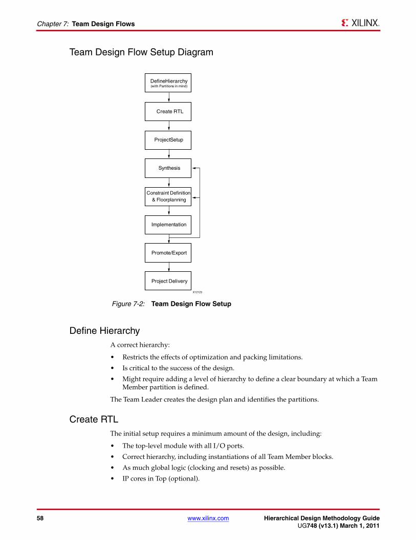
58 www.xilinx.com Hierarchical Design Methodology GuideUG748 (v13.1) March 1, 2011
Chapter 7: Team Design Flows
Team Design Flow Setup Diagram
Define HierarchyA correct hierarchy:
• Restricts the effects of optimization and packing limitations.
• Is critical to the success of the design.
• Might require adding a level of hierarchy to define a clear boundary at which a Team Member partition is defined.
The Team Leader creates the design plan and identifies the partitions.
Create RTLThe initial setup requires a minimum amount of the design, including:
• The top-level module with all I/O ports.
• Correct hierarchy, including instantiations of all Team Member blocks.
• As much global logic (clocking and resets) as possible.
• IP cores in Top (optional).
Figure X-Ref Target - Figure 7-2
Figure 7-2: Team Design Flow Setup

Hierarchical Design Methodology Guide www.xilinx.com 59UG748 (v13.1) March 1, 2011
Team Design Flow Setup
Each Team Member block can range from a black box to full Register Transfer Level (RTL). Module or component declaration is required to define the port directions and port widths.
Project SetupThe ISE Design Suite and the PlanAhead™ software both support Team Design flow. Both flows require some initial setup, including deciding on:
• Command line flow or PlanAhead software flow
• Synthesis tool
• Type of synthesis
• Synthesis and implementation options
• Source control
The Team Design flow allows for considerable flexibility in managing sources. Xilinx recommends that each Team Member have their own copy of the source files. To do so:
• Use a version control system.
• Allow each Team Member to have a local sandbox that can be updated as necessary.
Both the command line flow and the PlanAhead software flow support this method. PlanAhead software users can also copy the sources into the project. This allows all Team Members to have a local copy of common sources.
These methods allow one Team Member to update sources without affecting the other Team Members. If all Team Members share the same sources, changes to the source immediately affect all Team Members. This can cause exported implementation data to become stale. This recommendation allows modifications to be tested and verified prior to updating a golden repository.
Initial SynthesisThe initial synthesis should confirm that all modules are correctly defined.
Team Member modules can be:
• Full or partial RTL, or
• A module definition for a black box.
Because of its independent nature, the Team Design flow:
• Does not support a flat top-down synthesis flow.
• Requires either:
• A bottom-up synthesis flow, or
• A top-down incremental synthesis flow.
For bottom-up synthesis, the Team Member partitions are synthesized out of context with respect to Top. For this reason, the Team Members require only the synthesized netlist for Top. Implementation is in context.
60 www.xilinx.com Hierarchical Design Methodology GuideUG748 (v13.1) March 1, 2011
Chapter 7: Team Design Flows
The Team Design flow is based on the Xilinx Synthesis Technology (XST) incremental flow supported in the ISE Design Suite. In this flow, each Team Member partition is synthesized in context with Top. For this reason, each Team Member:
• Requires the top-level Hardware Design Language (HDL) code.
• Can import the top-level partition during synthesis to maintain results across all Team Member partitions.
For additional information, see:
• Chapter 3, Synthesis Partition Flows
Constraint DefinitionThe Team Leader creates a top-level User Constraint File (UCF) containing:
• I/O logic constraints and attributes, such as:
• I/O and LOC placement constraints
• IOSTANDARD timing constraints
• OFFSET IN/OUT timing constraints
• Global clock timing and placement constraints, such as:
• LOC constraints for BUFG/PLL/MMCM
• PERIOD constraints
• The placement of each Team Member partition using the AREA_GROUP constraint.
Since the Team Leader manages the clocking and global resources to ensure that each partition has access to needed resources, the Team Leader must be familiar with the target architecture.
Initial ImplementationAll implementations, including Team Member implementation runs, are in context with the top-level logic. The initial implementation might not yet yield meaningful placement or timing results, since most of the design is not present.
However, implementation can verify that:
• All modules are properly resolved.
• Partitions are correctly defined.
• All timing and physical constraints have correct syntax.
A partition defined as a black box is supported for synthesis and implementation with no special options or attributes. Even if some or all Team Member partitions are black boxes, it is still possible to implement these blocks because of the partition flow. The NGDBuild tool issues a warning that the partition is being implemented as a black box.
Promote or ExportSynthesis and implementation results can be promoted or exported at any stage.
During the initial design setup, it is unlikely that there will be any useful implementation data for a Top or a Team Member module. Nonetheless, it is possible that the top-level logic has a completed IP core that was also partitioned. Since each Team Member implements in

Hierarchical Design Methodology Guide www.xilinx.com 61UG748 (v13.1) March 1, 2011
Team Design Flow Setup
context with Top, the IP core can be exported for each Team Member to import during their implementation runs.
In the XST incremental flow, the Team Member can import the top-level synthesis results to achieve a consistent top-level across all Team Member partitions. This is not necessary if the Team Member uses a bottom-up synthesis flow, since each Team Member synthesis is out of context with Top.
Project DeliveryThe Team Leader provides the project files to each Team Member when:
• Partitions have been defined.
• Constraints have been created.
• The design has been synthesized and implemented.
Command Line Project Delivery
The command line project delivery includes:
• Synthesis projects
• HDL code
• UCF files
PlanAhead Software Project Delivery
The PlanAhead software project delivery includes:
• A copy of the Team Leader project for each Team Member
The Team Leader uses the Project > Save As command to give each Team Member their own copy. This ensures that all Team Members have identical data to start their development phase.

62 www.xilinx.com Hierarchical Design Methodology GuideUG748 (v13.1) March 1, 2011
Chapter 7: Team Design Flows
Team Member Responsibilities Each Team Member is responsible for the development, verification, and timing closure of their module. This process is repeated throughout the design cycle.
The required steps for each Team Member are:
• Develop and Update Module (Team Member)
• Module Synthesis (Team Member)
• Implementation (Team Member)
• Export or Promote (Team Member)
• Import (Team Member)
Team Member Development Flow Diagram
Develop and Update Module (Team Member)Developing and updating the module involves creating or modifying HDL code.
The Team Member:
• Creates or modifies their HDL code.
• Pushes any changes back up to the Team Leader if:
• The partition interface changes, or
• A new feature is implemented, or
• There is any change to the Team Member partition.
Figure X-Ref Target - Figure 7-3
Figure 7-3: Team Member Development Flow
������������ ����
���������
��������������
��������������
��������������
������������������ ������
������������������ ������
Hierarchical Design Methodology Guide www.xilinx.com 63UG748 (v13.1) March 1, 2011
Team Member Responsibilities
The Team Leader:
• Updates the top-level.
• Pushes the top-level back down to the other Team Members.
Module Synthesis (Team Member)Each Team Member module can be synthesized:
• Independently from Top using a bottom-up flow.
The Team Leader provides the top-level netlist to each Team Member for implementation.
• In context with Top using an incremental flow.
• Each Team Member requires the top-level HDL code to synthesize their module in context with Top.
• The results from the latest Team Leader run can be imported to prevent the top-level logic from varying among Team Members.
Implementation (Team Member)The Team Member implements the block in context with the top-level partition.
Xilinx recommends that you:
• Set the top-level partition to implement in most cases.
• Always set the other Team Member blocks to import, or implement them as a black box.
• Import other Team Member partitions from a Team Leader assembly run that met all partition interface timing.
For more information on closing timing when other Team Member partitions are implemented as black boxes, see:
• Black Box Usage in Chapter 1, Partitions
The Team Member uses all available methods to close timing, including:
• Creating physical constraints such as:
• AREA_GROUP
• LOC
• Creating special timing constraints, such as
• Multi-cycle paths
• False paths
• Using software options.
• Using tools such SmartXplorer.
It might not be necessary to push all the constraints back up to the Team Leader if the Team Member partition is being imported. However, they should be readily available in case the Team Leader needs to implement the Team Member partition.
As the Team Member pushes up a new version of their block to the Team Leader, the Team Leader:
• Validates the timing with the latest version of the design.
• Exports new results for all Team Members.

64 www.xilinx.com Hierarchical Design Methodology GuideUG748 (v13.1) March 1, 2011
Chapter 7: Team Design Flows
Xilinx recommends that each Team Member implement (instead of import) the top-level for implementation until the design begins to converge. The Team Member can then decide whether to import or implement Top.
Export or Promote (Team Member)To prevent unexpected results in the final assembly, Xilinx recommends that each Team Member export (command line) or promote (PlanAhead software) their results to the Team Leader frequently throughout the design process. This process allows potential issues to be identified and fixed when during development.
Import (Team Member)Each Team Member can import or implement other partitions for synthesis and implementation. While there is considerable flexibility in this task, Xilinx recommends that each Team Member:
• Import the top-level partition during synthesis, if using incremental synthesis.
• Implement the top-level partition during implementation at least until the design is complete enough that the exported results from an assembly run accurately represent the placement and routing required by the final design.
• Import (or black box) other Team Member blocks during synthesis, if using incremental synthesis.
• Import (or black box) other Team Member blocks during implementation.
Each Team Member should import a Team Member block from the promoted Team Leader assembly run, not directly from other Team Members. This ensures that all Team Members are working on the same version of the design.
Team Leader ResponsibilitiesThe Team Leader manages the assembly flow. The goal of the assembly flow is to achieve a completely assembled design that:
• Is fully placed and routed.
• Meets timing.
Assembly might be easy or difficult depending on:
• How full and how fast the design is, and
• How closely the Team Members work together throughout the design flow.
Assembly is an iterative process. As each Team Member obtains new results to share with the Team Leader and the other Team Members, they export this data to the Team Leader for an assembly run.
Based on the results of the assembly run, the Team Leader either:
• Works with individual Team Members to resolve issues, or
• Exports the successful results to all Team Members.
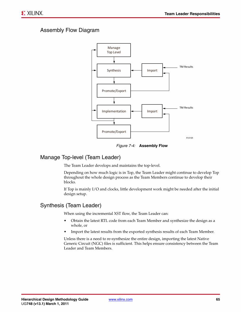
Hierarchical Design Methodology Guide www.xilinx.com 65UG748 (v13.1) March 1, 2011
Team Leader Responsibilities
Assembly Flow Diagram
Manage Top-level (Team Leader)The Team Leader develops and maintains the top-level.
Depending on how much logic is in Top, the Team Leader might continue to develop Top throughout the whole design process as the Team Members continue to develop their blocks.
If Top is mainly I/O and clocks, little development work might be needed after the initial design setup.
Synthesis (Team Leader)When using the incremental XST flow, the Team Leader can:
• Obtain the latest RTL code from each Team Member and synthesize the design as a whole, or
• Import the latest results from the exported synthesis results of each Team Member.
Unless there is a need to re-synthesize the entire design, importing the latest Native Generic Circuit (NGC) files is sufficient. This helps ensure consistency between the Team Leader and Team Members.
Figure X-Ref Target - Figure 7-4
Figure 7-4: Assembly Flow
���!����������
���������
��������������
��������������
��������������
������� � ������
������� � ������

66 www.xilinx.com Hierarchical Design Methodology GuideUG748 (v13.1) March 1, 2011
Chapter 7: Team Design Flows
Implementation (Team Leader)Implementation in the assembly phase uses the latest results from each Team Member. The Team Leader:
• Addresses any timing issues within the top-level partition, and
• Identifies timing issues between Team Member partitions.
• Manages the constraint files.
Team Member User Constraint File (UCF)
Each Team Member might have a User Constraint File (UCF) in addition to the top-level UCF. The Team Member UCF contains timing or placement constraints specific to the Team Member block.
To incorporate these constraints into the Team Leader implementation, the Team Leader:
• Manually concatenates the files, or
• Adds multiple UCF files to the PlanAhead software project, or
• Specifies multiple UCF files at the command line (NGDBuild tool)
If there are multiple UCF files, there must be no overlapping constraints. If two constraints constrain the same logic with different values, the last constraint read in by the implementation tools prevails. This conflict can lead to unpredictable results.
Importing or Implementing Team Member Blocks
During implementation, the Team Leader must implement or import or each Team Member block.
• Implementing each Team Member block:
• Allows for more flexibility in the placement of Top.
• Might be necessary early in the design cycle to identify timing issues.
• Importing each Team Member block can take place as:
• The block becomes more complete, and
• Partition interface timing is met.
Final Assembly
Final assembly occurs when every Team Member block is finalized. At this stage:
• Each Team Member block is imported.
• Top might be implemented or imported depending on the timing results.
• The preservation level on a Team Member block might be relaxed.
Relaxing the preservation level allows minor placement and routing adjustments to a Team Member block that is being imported.
• Individual partitions can be set to implement if:
• Small changes are made to one Team Member block, or
• Timing does not converge on the assembly run.

Hierarchical Design Methodology Guide www.xilinx.com 67UG748 (v13.1) March 1, 2011
Team Leader Responsibilities
Promote or Export (Team Leader)As each Team Member provides the Team Leader with more complete versions of their blocks, the implementation results begin to converge. The Team Leader exports (or promotes) the latest synthesis and implementation results to each Team Member.
Each Team Member should import a Team Member block from the promoted Team Leader assembly run, not directly from other Team Members. This ensures that all Team Members are working on the same version of the design.
In most cases, the Team Leader exports the implementation data only. However, the Team Leader might also:
• Promote the synthesis results so that all Team Members have the latest netlist for every other Team Member block.
• Iterate on synthesis of the top-level while importing each Team Member block.
Import (Team Leader)The Team Leader decides whether to import or implement each Team Member block for:
• Synthesis, when incremental synthesis is used
Xilinx recommends that the Team Leader:
• Import the Team Member results, or
• Use the XST read_cores option to read in the latest NGC file for each block.
• Implementation
Xilinx recommends that the Team Leader import the Team Member block whenever possible.
If interface timing to the top-level or other Team Member blocks is not met, it might be necessary to implement some or all the Team Member blocks until interface timing is stable.
Changing the Preservation Level
The Team Leader can change the preservation level of imported partitions:
• To placement if:
• Routing conflicts occur.
Changing the preservation level to placement allows the router to change the routing.
• To synthesis if:
• Timing is not met, or
• Placement conflicts occur.
Changing the preservation level to synthesis allows the implementation tools to make minor changes to placement and routing. If the Area Group constraint requirements for the Team Design flow are followed, no placement conflicts should occur.
68 www.xilinx.com Hierarchical Design Methodology GuideUG748 (v13.1) March 1, 2011
Chapter 7: Team Design Flows
Changing the Partition State
The Team Leader can change the partition state from import to implement when:
• Adjusting the preservation level does not allow the design to converge, or
• Small changes are made to an already assembled design.
Design RecommendationsThe following design recommendations apply to all partition-based designs, including the Team Design flow:
• Register signals on both sides of the partition boundary.
• Partition logic into groups that are functionally independent from the rest of the design.
• Keep logic that must be packed together inside the same partition.
The following design recommendations apply specifically to the Team Design flow:
• Each Team Member block (excluding the top-level Team Leader logic) must be Area Grouped to a specific region of the device.
• If possible, provide a stage of pipeline registers for timing critical paths going from one partition to another (Team Leader to Team Member, or Team Member to Team Member) in the top-level partition. Because of the Area Group requirement of Team Design flow, this allows more flexibility to meet timing to logic that is placement-restricted (for example, Team Member blocks).
• Black Box modules are supported.
If a Team Member module does not yet exist, or if a black box is desired for timing or run time benefits, it can be left as a black box for both synthesis and implementation.
For more information on Black Boxes, see:
Black Box Usage in Chapter 1, Partitions
• The top-level design contains all I/O buffers.
• The top-level design is limited to a small amount of logic.
What constitutes a “small” amount of logic is open to interpretation, and is often design dependent. In general, the more logic in Top, the more complicated the final assembly. Child partitions inside Top that belong to the Team Leader help keep the amount of logic implemented during assembly to a minimum.
ISE Design Suite Command Line FlowThe command line flow requires no special switches or tools. All partition information is stored in the PXML file.
The Team Leader and the Team Members can use SmartXplorer to identify the implementation options that work well for the particular design.
For more information, see:
• Using SmartXplorer in Partitioned Designs in Chapter 5, PlanAhead Partition Flows
Hierarchical Design Methodology Guide www.xilinx.com 69UG748 (v13.1) March 1, 2011
ISE Design Suite Command Line Flow
When running the Team Design flow from the command line, each Team Member (including the Team Leader) manages their own PXML file. The PXML file must be named xpartition.pxml.
For sample PXML files, see:
• Sample PXML File (Team Leader)
• Sample PXML File (Team Member)
Command Line Flow Directory StructureThere is no required directory structure for a TD project. Source files are commonly controlled with a version control system such as Perforce or CVS. Each Team Member checks out a local sandbox from the repository.
The following sample directory structures can be used to begin the project.
Team Leader Command Line Flow Directory Structure
• TL
• Synth
Synthesis Results of Top and Team Member partitions
Note: For bottom-up or incremental synthesis projects
• HDL
- VHDL or Verilog source files for the Team Member block
- Black box module definitions for Team Member partitions that do not yet exist
• UCF
- Top-level UCF files
- TM-specific UCF files
• Impl
- Top-level implementation results
- Latest version of each Team Member design
- xpartition.pxml
• XImpl
- Exported or Promoted results of the latest implementation
Team Members can import Top and other Team Member blocks from this directory. If some Team Members lack easy access to this location, choose a more suitable export location.
• Assemble
- Final implementation of design in which each Team Member block is imported.
- Top might be implemented or imported depending on timing results.

70 www.xilinx.com Hierarchical Design Methodology GuideUG748 (v13.1) March 1, 2011
Chapter 7: Team Design Flows
Team Member Command Line Flow Directory Structure
• TM
• Synth
- Synthesis results of the Team Member block for a bottom up synthesis project, or
- Results of Top plus the Team Member block (incremental synthesis in context with top)
If little HDL exists for the Team Member block, this should be the synthesis results of a proxy HDL file in which all inputs and outputs are registered for interface timing purposes to other partitions.
• HDL
- VHDL or Verilog source files for the entire design
- VHDL or Verilog source files for Top (if using in context incremental synthesis flow)
- Black box module definitions for Team Member partitions that do not yet exist
• UCF
- Top-level UCF files
- TM-specific UCF files with specific physical constraints to the Team Member partition, such as LOC and AREA_GROUP
• Impl
- Implementation results of the Team Member block that imports other Team Member blocks and implements or imports Top.
- xpartition.pxml
• XImpl
- Exported results of the latest Team Member implementation
Can be used by the Team Leader to import the Team Member block for assembly runs.
If the Team Leader lacks easy access to this location, choose a more suitable export location.
Team Leader Command Line Flow ResponsibilitiesThe Team Leader implements the entire design with the latest version of Top and each Team Member block. As with all implementations in this flow, a partition is placed on each Team Member block and on Top. When a lower level partition is added to the design, Top must be a partition.

Hierarchical Design Methodology Guide www.xilinx.com 71UG748 (v13.1) March 1, 2011
ISE Design Suite Command Line Flow
Sample PXML File (Team Leader)
<?xml version="1.0"?><Project Name="impl_1" FileVersion="1.2" ProjectVersion="2.0"><Partition Name="/top" State="implement" ImportLocation="NONE"><Partition Name="/top/U0" State="implement" ImportLocation="NONE" Preserve="routing"></Partition><Partition Name="/top/U1" State="implement" ImportLocation="NONE" Preserve="routing"></Partition><Partition Name="/top/U2" State="import" ImportLocation="../../TM3/Ximpl"
Preserve="routing"></Partition>
</Partition>
As Team Member blocks become finalized, and for the final assembly, the state of each Team Member partition can be set to import. The ImportLocation now points to the directory to which the Team Member partition was exported. After a successful implementation, the Team Leader exports the results to the Team Members.
The Team Members might import or implement Top, but should always import other Team Member blocks from this exported Team Leader run.
Team Member Command Line Flow ResponsibilitiesEach Team Member implements their design in context with Top while importing other Team Member partitions. Each Team Member will likely implement the top partition, providing more flexibility for the individual Team Member block.
As the design converges, and the Team Member tweaks a Team Member block, Top can be imported to help preserve interface timing.
After successfully implementing the design, the Team Member:
• Exports the implementation results for the Team Leader.
• Provides the Team Leader with the latest version of the source (netlist and possibly HDL) for their block.
This ensures synchronization of the source and exported partition data, and prevents any false logic change detection errors in the NGDBuild tool.
After running implementation with the latest version of the design, the Team Leader exports the results to all Team Members.
Each Team Member should import a Team Member block from the promoted Team Leader data, not directly from other Team Members. This ensures that all Team Members are working on the same version of the design.

72 www.xilinx.com Hierarchical Design Methodology GuideUG748 (v13.1) March 1, 2011
Chapter 7: Team Design Flows
Sample PXML File (Team Member)
<?xml version="1.0"?><Project Name="impl_1" FileVersion="1.2" ProjectVersion="2.0"><Partition Name="/top" State="import" ImportLocation="../../TL/Ximpl "><Partition Name="/top/U0" State="implement" ImportLocation="NONE" Preserve="routing"></Partition><Partition Name="/top/U1" State="import" ImportLocation="../../TM2/Ximpl"
Preserve="routing"></Partition><Partition Name="/top/U2" State="import" ImportLocation="../../TM3/Ximpl"
Preserve="routing"></Partition>
</Partition></Project>

Hierarchical Design Methodology Guide www.xilinx.com 73UG748 (v13.1) March 1, 2011
PlanAhead Software Flow
PlanAhead Software FlowWhile it is possible to perform synthesis outside of the PlanAhead software, and use netlist-based PlanAhead software projects to implement a Team Design flow, this section assumes the use of RTL PlanAhead software projects with the XST incremental flow. No special PlanAhead software settings or licenses are required.
For more information, see:
• Chapter 5, PlanAhead Partition Flows
Team Leader Responsibilities (PlanAhead Software Flow)The Team Leader follows these steps in the PlanAhead software flow:
1. Creates an initial RTL PlanAhead software project.
• The project might contain all source files that exist at this stage of the design.
• The project must contain a top-level HDL file which instantiates a black box for the various Team Member modules.
• The project should follow the source management recommendations described in the previous section of this chapter.
2. Defines partitions on the Team Member blocks using the RTL Design view.
• Defining partitions requires elaboration of the HDL.
• If the HDL has errors and will not elaborate, partitions cannot be defined.
3. Runs synthesis.
4. Promotes successful results.
5. Adds or creates any necessary global constraints, including:
• Timing constraints, such as:
- PERIOD
- OFFSET
- FROM:TO
• Physical constraints, such as:
- AREA_GROUP constraints for Team Member blocks
- LOC constraints for clocking logic and I/O
This is referred to as floorplanning.
6. Validates the current design by:
• Running the PlanAhead software Design Rules Check (DRC).
• Running the current design through implementation.
While there might not be useful implementation results at this stage, validating the design provides a check of the design and constraints through the implementation tool’s logical and physical DRC checks.
7. Creates one project per Team Member with Project Save As.
As each Team Member develops, implements, and promotes their block, this step can be repeated to keep all Team Member projects in sync with the Team Leader project. These steps are summarized in the following figure.

74 www.xilinx.com Hierarchical Design Methodology GuideUG748 (v13.1) March 1, 2011
Chapter 7: Team Design Flows
Interface TimingSpecifying the interface timing between partitions in order to meet and maintain timing can be difficult. Often, one partition is being implemented while another is being imported. The tools are unable to place the logic in the ideal locations.
There are two methods to resolve this dilemma, depending on the flow being used.
• Team Member Partitions as Black Boxes
Constraining the interface logic of one Team Member partition when the other Team Member partitions are defined as black boxes.
• Team Member Partitions as Interface Logic
Constraining, meeting, and maintaining interface timing between Team Member partitions when all interface logic is present (no black boxes).
Figure X-Ref Target - Figure 7-5
Figure 7-5: Initial Team Leader PlanAhead Flow

Hierarchical Design Methodology Guide www.xilinx.com 75UG748 (v13.1) March 1, 2011
Interface Timing
Team Member Partitions as Black BoxesInterface timing can be budgeted with constraints to the partition pins when:
• The current Team Member is implementing only their logic along with Top, and
• Other Team Member partitions are black boxes.
The Team Leader initially creates partition pin timing constraints.
For an example of constraining proxy logic on a black box module, see:
• Black Box Usage in Chapter 1, Partitions
Once these partition pin timing constraints are defined, the Team Leader implements the design with all Team Member partitions defined as black boxes. Once implementation is complete and interface timing is met, the partition pin locations can be exported by promoting the black box partitions.
The Team Members can use this promoted data, along with the appropriate timing constraints, when implementing their block in order to:
• Place the interface logic near the appropriate edge of the partition AG range.
• Meet timing in assembly.
If the locations of the PROXY pins need to be adjusted from the initial Team Leader implementation, use pr2ucf to extract the constraints.
pr2ucf top_routed.ncd -o partition_pins.ucf
These constraints:
• Can be modified manually.
• Cannot be modified using the PlanAhead software.
The modified locations are passed to each Team Member by:
• Adding the additional UCF to the design flow, or
• Merging the constraints with the top-level UCF.
Since the partition pin locations are fixed by means of UCF constraints, the black box modules should be implemented (as opposed to imported) by each Team Member.
The Team Leader can now:
• Re-implement the black boxes with the modified partition pin locations.
• Re-export (or promote) the results for each Team Member.
Implementing one module with black boxes for the other Team Member partitions can lower memory and runtime. However, this flow runs the risk that the interface timing might not be fully accurate, since:
• No clock skew, fanout, or realistic levels of logic are considered.
• Interface timing issues can arise during assembly.
For more information on using this flow to reduce memory, see:
• Managing Memory Usage on Large Designs in Chapter 1, Partitions
Team Member Partitions as Interface LogicInterface timing can often be ignored early in the design cycle. Each Team Member implements their block while either importing other Team Member blocks, or leaving them

76 www.xilinx.com Hierarchical Design Methodology GuideUG748 (v13.1) March 1, 2011
Chapter 7: Team Design Flows
as black boxes. Once a Team Member block has its interface logic defined, the code is pushed back to the Team Leader, who implements all partitions.
The Team Leader:
• Identifies and resolves interface timing issues.
• Promotes the results are promoted for all Team Members to use.
Team Member A can continue developing and implementing their block while importing Team Member B from the promoted Team Leader results. Team Member B does the same for Team Member A. The partition interface timing should remain intact.
The advantages to this flow are:
• The interface timing is 100% accurate.
• Interface timing issues can be identified earlier in the flow when changes are still being made.
• No special timing or placement constraints have to be created. There is aa normal PERIOD in most cases.
Team Member Responsibilities (PlanAhead Software Flow)Each Team Member now has a PlanAhead software project identical to the Team Leader project.
Each Team Member:
1. Develops and adds their sources to the project.
2. Synthesizes, constrains, implements, and promotes their results.
The projects now begin to diverge. Xilinx recommends that Team Members periodically synchronize their projects with the Team Leader project.
Once a Team Member has results that can be used by other Team Members and the Team Leader, they promote the synthesis and implementation results to a location that the Team Leader can access.
The Team Leader:
1. Runs synthesis, implementation, or both, using the latest version of the design.
2. Promotes those results for the Team Leader to run assembly.
Each Team Member should import a Team Member block from the promoted Team Leader assembly run, not directly from other Team Members. This ensures that all Team Members are working on the same version of the design.
Hierarchical Design Methodology Guide www.xilinx.com 77UG748 (v13.1) March 1, 2011
Implementation Errors
Chapter 8
Debugging Partitions
This chapter discusses Debugging Partitions, and includes:
• Implementation Errors
• BitGen DRC Errors
• ChipScope Support
Implementation ErrorsThis section discusses Implementation Errors, and includes:
• Error When Trying to Import
• A Design Does Not Meet Timing
• A Design Does Not Place
• A Design Does Not Route
• Slice Utilization Goes Up With Partitions
Error When Trying to ImportThe following error message usually indicates that the PXML file was not copied to the import directory.
ERROR:HierarchicalDesignC:154 - Import project "./import" is not an XPartition project.ERROR:HierarchicalDesignC:143 - Error importing Partition "/top/modulea".ERROR:HierarchicalDesignC:142 - Error found in XPartition file data.
A Design Does Not Meet TimingIf a partitioned portion of a design does not meet timing, relax the preservation level of the imported partitions to synthesis. This allows small changes in placement and routing to the imported partitions. Since this gives the tools more flexibility, timing might be met.
Once timing is met:
• Export the partition.
• Move the preservation level to placement or routing (optional).

78 www.xilinx.com Hierarchical Design Methodology GuideUG748 (v13.1) March 1, 2011
Chapter 8: Debugging Partitions
If the design still does not meet timing, it might be necessary to:
• Change the state from import to implement on one or more of the partitions, or
• Remove one or more partitions that span critical paths.
Standard flat flow timing closure techniques apply.
A Design Does Not PlaceThe more partitions there are in a design, and the higher percentage of logic that is imported, the fewer resources are available for the logic being implemented. This might lead to a design that cannot be placed.
The following message during placement might indicate this problem.
WARNING: Place:1178 - 4 sites were unavailable during the placement phase because they were already used by routing within preserved Partitions. If the Placer is not able to find a successful solution, the following suggestions might help the Placer find a solution.1) To allow the Placer to use these sites, back off the preservation level on one or more of the following Partitions. The following Partitions contain unavailable sites: Partition /top/Control_Module: 3 (preserve=routing) Partition /top/Express_Car: 1 (preserve=routing)If the problem persists, then careful floorplanning can minimize the number of sites occupied by routing.
These sites are not usable because the imported routing makes one or more pins on an otherwise empty component unusable. Logic can be placed in these components if the router has the ability to move imported routing. To do so, change the preservation level to placement or synthesis on partitions with a high number of unavailable sites. If this is insufficient, you might need to re-implement a partition.
Setting the top partition state to implement might free up enough resources to allow the placer to find a valid placement. If this is insufficient, you might need to change the other partitions to implement as well.
Use the PlanAhead™ software to analyze which partitions to change to implement.
1. Load the placement and routing information in the Results Viewer.
2. Highlight each partition to see where its logic is located in the FPGA device.
Having too many partitions can negatively impact the utilization of a device. Remove partitions on modules that are not on critical portions of the design to free up resources for other logic. This gives the tools more flexibility to find a solution that meets timing.
Careful floorplanning can help designs find a permanent placement solution. If all the logic is allowed to spread out throughout the entire chip, the placer might be unable to find resources for the new logic being implemented. Floorplanning restricts each partition to its own section of the design. If an AREA_GROUP range is added or modified, the exported data of the partition is now out-of-date. The state of the partition must be set to implement for the next run.
A Design Does Not RouteIf a design with imported partitions does not route:
1. Change the preservation level to placement.
2. Re-run the PAR tool.

Hierarchical Design Methodology Guide www.xilinx.com 79UG748 (v13.1) March 1, 2011
Implementation Errors
You do not need to re-run the Map tool.
Just as floorplanning can help solve placement issues, it can also help solve routing issues.
If changing the preservation level does not yield the desired results, and if floorplanning has not helped, analyze the placed design to determine which partitions need to have the state changed.
Use the PlanAhead software to analyze which partitions to change to placement.
1. Load the placement and routing information in the Results Viewer.
2. Highlight each partition to see where its logic is located in the FPGA device.
Slice Utilization Goes Up With PartitionsSome increased utilization is expected due to the optimization and packing restrictions imposed by partitions. The increased utilization is usually only a few percentage points, and is ideally negligible.
Significantly Increased Utilization
Utilization can increase significantly if the ratio of LUTs to FFs highly favors one over the other.
• In a non-partitioned design, the packer can combine some components from moduleA with components in moduleB.
• In a partitioned design, due to packing restrictions, components from partitionA cannot be packed with components from partitionB. Empty slices must be used for this out-of-balance logic, causing slice utilization to increase.
Area Group and Partition Summary
To check whether a design is affected, review the Area Group and Partition Resource Summary section of the Map Report (.mrp).
Sample Map Report - Partition Resource Summary
Partition "/top/moduleA": State=implement Slice Logic Utilization: Number of Slice Registers: 4,318 (4,318) Number of Slice LUTs: 4,337 (4,337) Number used as logic: 3,717 (3,717) Number used as Memory: 620 (620) Slice Logic Distribution: Number of occupied Slices: 1,750 (1,750) Number of LUT Flip Flop pairs used: 5,249 (5,249) Number with an unused Flip Flop: 931 out of 5,249 17% Number with an unused LUT: 1,508 out of 5,249 28% Number of fully used LUT-FF pairs: 2,810 out of 5,249 53% Number of Block RAM/FIFOs: 3 (3) Number of BUFDS: 1 (1) Number of BUFR: 1 (1) Number of GTX_DUAL: 2 (2) Number of PLL_ADV: 1 (1)

80 www.xilinx.com Hierarchical Design Methodology GuideUG748 (v13.1) March 1, 2011
Chapter 8: Debugging Partitions
Utilization Numbers
The Map Report lists two numbers for the utilization:
• The first number shows the resources for the individual partition.
• The second number (in parentheses) shows the resources for the partition and all its child partitions.
This information appears at the top of the Partition Resource Summary section of the Map Report, and can easily be overlooked. Following is an example:
Partition Resource Summary:---------------------------Resources are reported for each Partition followed in parenthesis by resources for the Partition plus all of its descendents.
BitGen DRC ErrorsA design might complete the PAR tool, then fail in during the BitGen process, displaying Design Rules Check (DRC) errors such as:
ERROR:PhysDesignRules:10 - The network <signal_OBUF> is completely unrouted
This error is caused by an un-driven output of a partition connected to logic in the parent partition. The Map tool cannot optimize the logic in the parent partition as it can in a flat flow. This results in partially routed signals in the final design, which causes BitGen DRC errors.
This problem can sometimes be corrected by using the BoundaryOpt attribute on the partition. This allows the Map tool to trim the unconnected ports.
Since BoundaryOpt has limitations, you might need to correct this problem at the Hardware Design Language (HDL) level. In either case, modified partitions must be re-implemented.
ChipScope SupportThe ChipScope™ tool supports partitions.
Change the partition state to implement on any partition affected by a ChipScope core change.
Hierarchical Design Methodology Guide www.xilinx.com 81UG748 (v13.1) March 1, 2011
Appendix A
Additional Resources
Xilinx Resources • ISE® Design Suite: Installation and Licensing Guide (UG798):
http://www.xilinx.com/support/documentation/sw_manuals/xilinx13_1/iil.pdf
• ISE Design Suite 13: Release Notes Guide (UG631): http://www.xilinx.com/support/documentation/sw_manuals/xilinx13_1/irn.pdf
• Xilinx® Documentation: http://www.xilinx.com/support/documentation.htm
• Xilinx Global Glossary: http://www.xilinx.com/support/documentation/sw_manuals/glossary.pdf
• Xilinx Support: http://www.xilinx.com/support.htm
• Xilinx Data Sheets: http://www.xilinx.com/support/documentation/data_sheets.htm
ISE Documentation• ISE Documents:
http://www.xilinx.com/support/documentation/dt_ise13-1.htm
- Command Line Tools User Guide (UG628): http://www.xilinx.com/support/documentation/sw_manuals/xilinx13_1/devref.pdf
- Constraints Guide (UG625): http://www.xilinx.com/support/documentation/sw_manuals/xilinx13_1/cgd.pdf
- Xilinx Synthesis and Simulation Design Guide (UG626): http://www.xilinx.com/support/documentation/sw_manuals/xilinx13_1/sim.pdf
- XST User Guide for Virtex-4, Virtex-5, Spartan-3, and Newer CPLD Devices (UG627): http://www.xilinx.com/support/documentation/sw_manuals/xilinx13_1/xst.pdf
- XST User Guide for Virtex-6, Spartan-6, and 7 Series Devices (UG687): http://www.xilinx.com/support/documentation/sw_manuals/xilinx13_1/xst_v6s6.pdf
PlanAhead Documentation• PlanAhead Documentation:
http://www.xilinx.com/support/documentation/dt_planahead_planahead13-1_userguides.htm
• Methodology Guides: http://www.xilinx.com/support_documentation
82 www.xilinx.com Hierarchical Design Methodology GuideUG748 (v13.1) March 1, 2011
Appendix A: Additional Resources
- Floorplanning Methodology Guide (UG633): http://www.xilinx.com/support/documentation/sw_manuals/xilinx13_1/Floorplanning_Methodology_Guide.pdf
- Hierarchical Design Methodology Guide (UG748): http://www.xilinx.com/support/documentation/sw_manuals/xilinx13_1/Hierarchical_Design_Methodology_Guide.pdf
- Pin Planning Methodology Guide (UG792): http://www.xilinx.com/support/documentation/sw_manuals/xilinx13_1/ug792_pinplan.pdf
• PlanAhead User Guide (UG632): http://www.xilinx.com/support/documentation/sw_manuals/xilinx13_1/PlanAhead_UserGuide.pdf
• PlanAhead Tcl Command Reference Guide (UG789): http://www.xilinx.com/support/documentation/sw_manuals/xilinx13_1/ug789_tcl_commands.pdf
• PlanAhead Tutorials: http://www.xilinx.com/support/documentation/dt_planahead_planahead13-1_tutorials.htm
- Design Analysis and Floorplanning (UG676): http://www.xilinx.com/support/documentation/sw_manuals/xilinx13_1/PlanAhead_Tutorial_Design_Analysis_Floorplan.pdf
- I/O Pin Planning (UG674): http://www.xilinx.com/support/documentation/sw_manuals/xilinx13_1/PlanAhead_Tutorial_IO_Pin_Planning.pdf
- Leveraging Design Preservation for Predictable Results (UG747): http://www.xilinx.com/support/documentation/sw_manuals/xilinx13_1/PlanAhead_Tutorial_Design_Preservation.pdf


