HIGH- AND LOW-Btu GAS FROM MONTANA SUBBITUMINOUS COAL J. L. Arora K. B. Burnham C. L. Tsaros Institute of Gas Technology Chicago, Illinois 60616 U.S.A. INTRODUCTION 63 Two coal gasification processes are under development at IGT. The@HYGAS Process has been developed for high-Btu gas (SNG) from coal; the U-GAS Process, a much simpler system, has been developed for low-Btu gas. This paper describes the application of these gasifiers for different objectives and compares process and economic characteristics. HYGAS and U-GAS reactor systems are compared for the manufacture of pipeline gas, and the U-GAS Process is analyzed as an advantageous source of low-Btu gas. Three process designs and their economics for manufacturing a nominal amount of 240 billion Btu/day of product gas are discussed. The designs are based on the conversion of Montana subbituminous coal, whose analysis is given in Table 1. Because the coal is nonagglomerating, pretreatment is not required. Table 1. MONTANA SUBBITUMINOUS COAL Proximate Analysis Weight Percent Moisture Volatile Matter Fixed Carbon Ash Total 22.0 29.4 42.6 6.0 100.0 - Ultimate Analysis (Dry) Carbon 67.70 Hydrogen 4.61 Nitrogen 0.85 Oxygen 18.46 Sulfur 0.66 Ash 7.72 Total 100.00 Dry Heating Value, Btu/lb 11,290 72 1. I, E
Transcript
HIGH- AND LOW-Btu GAS FROM MONTANA SUBBITUMINOUS COAL
J. L. Arora K. B. Burnham C. L. Tsaros
Institute of Gas Technology Chicago, Illinois 60616
U.S.A.
INTRODUCTION 63
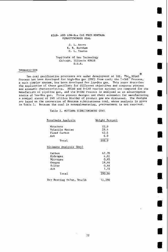
Two coal gasification processes are under development at IGT. The@HYGAS Process has been developed for high-Btu gas (SNG) from coal; the U-GAS Process, a much simpler system, has been developed for low-Btu gas. This paper describes the application of these gasifiers for different objectives and compares process and economic characteristics. HYGAS and U-GAS reactor systems are compared for the manufacture of pipeline gas, and the U-GAS Process is analyzed as an advantageous source of low-Btu gas. Three process designs and their economics for manufacturing a nominal amount of 240 billion Btu/day of product gas are discussed. The designs are based on the conversion of Montana subbituminous coal, whose analysis is given in Table 1. Because the coal is nonagglomerating, pretreatment is not required.
TWO PKOCeSs designs for the manufacture of 242 billion Btu/day of SNG at lo00 psig from coal have been made: utilizing the U-GAS Process. the HYGAS Process. A comparison of the two processes will show any economic benefit derived from the use of the more complex and costly HYGAS reactor in contrast to the simpler U-GAS reactor in the manufacture of pipeline gas from coal.
Comparison of the HYGAS and U-GAS Reactors
one based on the HYGAS Process and a similar design The capacity was set by an existing design based on
The HYGAS reactor (hydrogasifier) is designed to maximize direct methane for- mation by the reaction
Coal + 2H2 - CH4. 1)
This reaction supplies heat for the endothermic reaction also occurring in the hydrogasifier:
Coal + H20 - CO + H2. 2)
High pressure in the reactor, 1165 psig in this design, favors the formation of methane.
Process coal at a rate of 15,996 tons/day is dried to 10% moisture and simul- taneously ground to below 8 mesh with a maximum of 15% below 100 mesh. The pre- pared coal is pneumatically conveyed to the slurry preparation section, and a 50% water slurry is pumped to the hydrogasifier. A fluidized-bed dryer is located at the top of the vessel, where the slurry water is vaporized in contact with the hot reactor effluent gases.
The reactor coal feed passes through three zones of conversion: 1) a low- temperature (lOOO°F) transport reactor, where the coal is devolatilized and rapid- rate conversion to methane enriches the product gas; 2) the main fluidized bed at 1700°F, where most of the methane is formed; and 3) the steam-oxygen gasification zone at 1850"F, where synthesis gas is generated from the hydrogasifier char according to the endothermic steam decomposition reaction
Char + H 0 CO + H2. 3) 2 Heat is supplied by partial combustion of the char with oxygen:
c + o2 - co2. 4 )
Further generation of hydrogen occurs in zone 2, where the exothermic methane for- mation reaction supplies heat'for the steam decomposition reaction and 2 ) .
(Reactions 1
The U-GAS reactor is a single-stage fluidized-bed gasifier operating at 1900°F and 335 psig. The reactor is not primarily designed to make methane. To promote methane formation, where SNG is the desired end product, 18,400 tons/day of coal is fed into the upper portion of the gasifier onto the fluidized bed. The countercur- rent flow of hot gases and coal devolatilizes the coal, and some methane i s formed. Reactions 2 and 4 are the major reactions taking place in this system. A lockhopper coal feed system, which is used commercially at this relatively low pressure level, is used to feed the coal. Further operating details of the U-GAS system are dis- cussed in the section on low-Btu gas.
73
Raw gas composi t ions from t h e two r e a c t o r s a r e compared i n Table 2. The t o t a l moles p e r hour i s t h e requirement f o r 242 b i l l i o n Btu/day of product gas.
Table 2. COMPOSITION OF RAW GAS FROM GASIFIERS
HYGAS Hydrogas i f ie r U-GAS
E f f l u e n t Raw Gas
mol X co 20.13 34.18
18,65 13.30
23.68 29.52
22.68 17.44
12.86 4.84
HZ
H2°
cH4
NH3
H2S
-- 0.99
0.34
0.19 0.20
N2 + A r 0.18 0.52 B-T-X 0.30 __
100.00 100.00
T o t a l mol/hr 103,288 126,576
__ ‘ZH6
I n a d d i t i o n t o c o a l r a w material, genera t ion of these gases r e q u i r e s steam and oxygen. The HYGAS r e a c t o r r e q u i r e s 1,003,130 l b / h r of steam a t 1200 ps ig and 1O5O0F, plus 2999 tons/day of 98% oxygen. The U-GAS r e a c t o r r e q u i r e s 670,320 l b / h r of steam a t 385 p s i g and 800°F, p l u s 7986 tons/day of oxygen.
The Manufacture of P i p e l i n e Gas
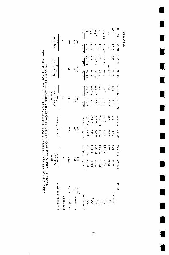
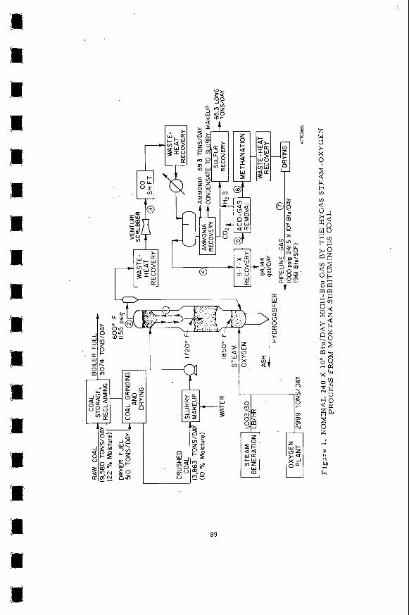
The raw gases from b o t h r e a c t o r s r e q u i r e upgrading t o pipel ine-gas q u a l i t y . For t h e HYGAS p l a n t , t h e r e q u i r e d s t e p s a r e shown i n t h e flow diagram of Figure 1, and t h e compositions of t h e process f low streams are given i n Table 3 . Table 4 give s i m i l a r in format ion f o r t h e U-GAS p l a n t .
Figure 2 and
SNG by HYGAS
The e f f l u e n t gas i s cooled by waste h e a t recovery and cleaned i n a v e n t u r i scrubber t o remove small p a r t i c l e s c a r r i e d over from t h e hydrogas i f ie r . The gas is sent t o a CO conversion r e a c t o r where t h e H / C O r a t i o i s r a i s e d t o 3.2 o r 3.3 i n prepara t ion f o r methanat ion. The c a t a l y s t is an o i l - and s u l f u r - r e s i s t a n t , high- temperature CO conversion c a t a l y s t . Steam f o r t h i s r e a c t i o n i s suppl ied by vapor- ized s l u r r y feedwater p r e s e n t i n t h e raw gas.
2
The B-T-X formed i n t h e h y d r o g a s i f i e r i s recovered as a va luable by-product O i l scrubbing and a c t i v a t e d carbon a r e used f o r t h i s operat ion. a f t e r CO conversion.
Large amounts of CO p i p e l i n e gas qual i t ; . t h i s s e c t i o n a r e s e n t t o a S t r e t f o r d u n i t f o r s u l f u r recovery. H S a r e removed by a c t i v a t e d carbon and z inc oxide beds.
and H S must b e removed from t h e gas dur ing t h e upgrading t o Thig is done by h o t carbonate scrubbing; a c i d gases l e a v i n g
F i n a l t r a c e s of
2
14
rn
N
" N +
" N -
m m .,
0 0 il
0
0 -
m
75
ri
m N
0 0 -.
-0 t- m
0 0 IC ,-.
O m * N * *
m o m t - N N
o m m m m m
O m m m r i m
76
The purified gas is methanated in a fixed-bed reactor where essentially all the CO and some of the C02 are converted by the following reactions:
CO + 3H2 CH4 + H20 5)
C02 + 4H2 CH4 + 2H20. 6 )
Temperature is controlled by recycling the product so as to dilute the CO content in the feed mixtures to the four reactor stages to about 4%. This limits the maxi- mum catalyst bed temperature to 900'F. A product gas of 961 Btu/SCF HHV leaves the plant at 1000 psig.
Water condensate from CO conversion effluent goes through oil-water separation and a Chevron waste-water treatment process. Stripped gases go to an ammonia re- covery section where 69 short tons/day are recovered as by-product. Acid gases are combined with those from the hot carbonate section and sent to the Stretford unit. The by-product sulfur is 65.3 long tons/day. 84,144 gal/day.
Total by-product B-T-X recovery is
SNG by U-GAS
The flow diagram for this process (Figure 2 ) shows major steps similar to those for the HYGAS Process. However, there are several important differences.
1. Because of the much lower operating pressure, the U-GAS system uses lockhoppers to feed the dried, ground coal to the reactor instead of slurry feed.
2. We have assumed that ammonia is not formed, and since the U-GAS reactor does not make B-T-X, recovery systems f o r these materials are not required.
3. The steam for CO conversion is generated by adiabatic humidification of the hot (1700'F) raw gas in the venturi scrubber, recovering heat in cooling to 380'F.
4. Because of the lower gasifier pressure compared with HYGAS (335 VS. 1165 psig), subsequent compression to 450 psig before acid-gas removal and final product compression to 1000 psig are required.
Comparison of HYGAS~n~-_or the Manufacture of Pipeline Gas Gasifier and process parameters, process energy balances, and efficiencies for
the manufacture of pipeline-quality gas by the HYGAS and U-GAS Processes are shown in Tables 5, 6, and 7. The utility requirements for each process design were esti- mated, and complete energy balances were made. Both plants have coal-fired boilers for steam and power generation.
The gasifier feed quantities are presented in Table 5. The U-GAS reactor con- sumes about 157: more coal than the HYGAS reactor at equal carbon conversions of 98%. However, the steam requirement for U-GAS is about 67% of that for HYGAS; this is because the U-GAS reactor operates at 1900°F and HYGAS has reaction zones at 1000°, 1700", and 1850"F, so the reaction rates are higher. The most significant differ- ence in gasifier feeds is in the amount of oxygen. 7986 tons/day of oxygen, which is about 2.7 times as much a; required by the HYGAS reactor. The proportionately larger U-GAS oxygen plant is one of the major factors contributing to the greater utility requirements and higher costs for U-GAS as com- pared with HYGAS.
The U-GAS reactor requires
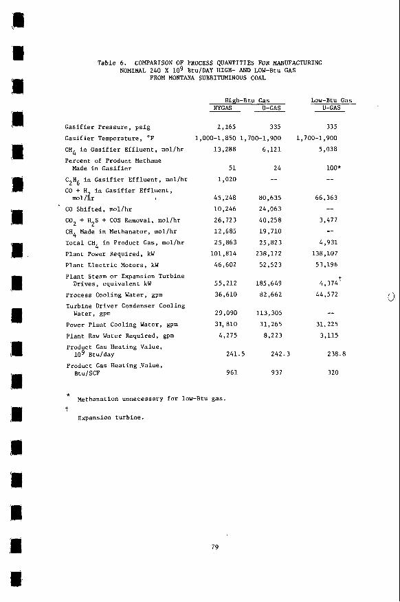
Table 6 is a comparison of important process quantities for each design. The HYGAS reactor operates at over 1000 psig as compared with the 335 psig operating
77
Y - a 4 m 0 0 url
x in0 U W N rl
% $ H Z
F z
m P-
in " I \ D l
h
a W w
rl
U 0 U
w 0
m . N v
$4
0 U
4
Y
h h
a - - h
2z . n u r lc
-n Fir(
0 - ur l
b o o u U
u r l m w w 5 ffib
.
h W
5 U
m .d
P w N N v
U c . fl
$4 0 U U
m d
c a- .h m u c .d o u U 5 a
e&-? Mm
0
a m
2-
* $4 c e rl . B U rn
U w 4
R 0 U
U w rl c
0 V
W
5 0 U
M G .d
0 M
fii U (0
Table 6. COMPARISON OF PROCESS QUANTITIES FOR MANUFACTURING NOMINAL 240 X lo9 Btu/DAY HIGH- AND LOW-Btu GAS
FROM MONTANA SUBBITUMINOUS COAL
Gasifier Pressure, psig
Gasifier Temperature, OF
CH4 in Gasifier Effluent, mol/hr
Percent of Product Methane
C H in Gasifier Effluent, mol/hr CO + H in Gasifier Effluent,
CO Shifted, mol/hr
Cog + H2S + COS Removal, mol/hr CH4 Made in Methanator, mol/hr Total C H 4 in Product Gas, mol/hr
Plant Power Required, kW
Plant Electric Motors, kW
Plant Steam or Expansion Turbine Drives, equivalent kW
Process Cooling Water, gprn
Turbine Driver Condenser Cooling
Made in Gasifier
2 6
mol/ir ,
Water, gpm
Power Plant Cooling Water, gpm
Plant Raw Water Required, gpm
Product Gas Heating Value, lo9 Btu/day
Btu/SCF Product Gas Heating .Value,
High-Btu Gas HYGAS U-GAS ~-
1,165 335 1,000-1,850 1,700-1,900
13,288
51 1,020
45,248 10,246 26,723
12,685 25,863 101,814 46,602
55,212 36,610
29,090 31, 810
4,275
241.5
961
* t
Methanation unnecessary for low-Btu gas.
Expansion turbine.
79
6,121
24 --
80,635 24,063 40,258 19,710 25,823 238,172 52,523
185,649 82,662
113,305 31,265 8,223
Low-Btu Gas U-GAS
335 1,700-1,900
5,038
100" --
66,363 --
3,477 --
4,931 138,107 53,196
4,374 44,572
t
-- 31,225 3,115
242.3 238.8
937 320
3
m
0 0 0 r l N m N 0
O U O N r - r l N 0 4. . . . . . . . . 9
PI 10
,Ili
b pressure for the U-GAS reactor. multistage hydrogasification reaction, HYGAS produces more methane in the reactor: 13,288 mol/hr of CH4 and 1,020 mol/hr of ethane as compared with 6,121 mol/hr of methane for U-GAS. The amount of methane in the product gas is about the same (25,800 mol/hr) for both designs. However, the U-GAS reactor makes only 24% of this total as compared with 51% by the HYGAS reactor. output of methane, a U-GAS system requires more synthesis gas, hence more oxygen, and bigger CO shift, acid-gas removal, and methanation sections. The comparable quantities of CO shifted, acid-gas removed, and methane made in the methanator for both the HYGAS and U-GAS designs are shown in Table 6.
Because of the higher operating pressure and the
To achieve the same total plant
Table 6 also indicates the substantially higher power, cooling water, and raw water requirements for the U-GAS design due to the higher oxygen usage and to the power requirement for product gas compression to 1000 psig.
Table 7 presents a comparison of overall energy balances and process effici- encies. SNG via the U-GAS Process requires about 20% more plant coal, and the coal- to-pipeline gas efficiency is 58.2% versus 70% for the HYGAS system. HYGAS has 4.0% of the feed coal HHV converted to by-products, whereas the U-GAS system has only 0.2% converted, raising the HYGAS plant efficiency. system has considerably more heat dissipated to cooling media: million Btu/hr, o r 31.8% VS. 17.2% of plant coal feed. to cooling water is less than half that for the U-GAS system. This is primarily due to the very large difference in the amount of cooling necessary f o r the con- densers on the plant turbine drivers, 84,215 gpm. The difference in process cooling, while significant, is relatively minor by comparison. Overall efficiencies (coal to all products) are 74.0% for HYGAS and 58.4% for U-GAS.
LOW-Btu GAS BY THE U-GAS PROCESS
In addition,
The U-GAS 5504 VS. 2471
The HYGAS system heat l o s s
Figure 3 shows the flow diagram f o r producing low-Etu gas by the U-GAS Process, an appropriate application for this process, and the process flow streams are given in Table 8. The results are more favorable than in the SNG application and are shown in Tables 5, 6, and 7. To put this plant on a comparable basis with the other plants in this study, the same product fuel value output rate was used for all three. When making low-Btu instead of high-Btu gas with the U-GAS reactor, the process coal feed is reduced to 15,193 tons/day of Montana subbituminous coal, and the plant produces 239 billion Btu/day of 320 Btu/SCF fuel gas.
For the low-Btu !-GAS reactor process, coal is dried to 10% moisture and ground to 1/4 in. X 0. Lockhoppers introduce the coal to the gasifier. Simultaneous with gasification, ash is removed from the fluidized bed by an ash-agglomerating tech- nique, and fines elutriated from the bed returned throughcyclones. The gasifier requires 551,724 lb/hr of steam and 6,573 tons/day of oxygen. 315°F in a waste heat boiler and is water-scrubbed in a venturi scrubber for dust removal.
Raw gas is cooled to
Some adiabatic humidification occurs in the scrubber that cools the gas to 293°F. Prior to H S removal, the gas is cooled to 100"F, and the condensed water is sent to waste-water treating facilities and used as cooling tower makeup.
2
The hydrogen sulfide in the raw gas is removed by the Selexol Process. Besides hydrogen sulfide, a small amount of carbonyl sulfide is produced in the gasifier, and this compound is also partly removed by the Selexol Process. The total sulfur present in the clean gas is reduced to about 70 ppm. Together with hydrogen sulfide, the process removes about 24% of the carbon dioxide present in the raw gas. The H S-CO mixture from the Selexol unit is sent to a Stretford unit where 68 long tons/ day of sulfur is recovered. 2 2 The clean desulfurized gas from the Selexol absorber
81
9 m CI
I
n 0 0 -
a2
is heated to 700°F and then expanded in a power recovery turbine. Most of this energy (108,000 hp) is used to drive the oxygen plant air compressors, which are coupled to the expander shaft; also, 5,866 kW of electricity is generated and used to drive plant motors. The expanded gas is cooled to lOOOF and sent to boilers.
COMPARISON OF HIGH-Btu (HYGAS) AND LOW-Btu (U-GAS) PROCESSES
Both the HYGAS and the U-GAS Processes provide alternative energy sources through coal conversion techniques. specifically designed for the form of energy product desired. The SNG from HYGAS is f o r the higher valued pipeline gas, while the low-Btu gas from U-GAS is designed for use as industrial boiler fuel for process steam generation or for combined gas turbine- steam turbine power cycles.
The process differences result because each is
The U-GAS system is simpler than the HYGAS system because it requires no equip- ment to produce methane o r remove liquid hydrocarbons. For example, the U-GAS Procpqs does not require CO conversion, benzene recovery, r:ethanation, or CO removal (the mGAS Process uses the hot carbonate system, which removes COz, and $he U-GAS Process uses Selexol, which minimizes CO removal).
2
The gasifier inputs, process quantities, energy balances, and process effici- encies are presented in Tables 5 , 6, and 7 for the high- and low-Btu gas Both plants have boilers for steam and/or power generation.
processes.
Table 5 presents coal, gasifier steam, and oxygen requirements. The HYGAS re- actor requires 5% more coal than the U-GAS reactor, but the total coal needed, in- cluding fuel coal, is 16% more for the HYGAS Process. Fuel coal for U-GAS is less than half that f o r HYGAS because of the large amount of power recovered by expanding the product gas down to 10 psig. The U-GAS oxygen requirement is 6,573 tons/day, which is over twice the HYGAS requirement. This disadvantage in oxyzen plant costs and utilities is more than compensated for by the much simpler product upgrading when making low-Btu gas. reactor, and HYGAS also requires about 960,000 lb/hr of CO-shift steam.
The HYGAS reactor requires 80% more steam than the U-GAS
In Table 6 process quantities for the two processes are compared. Plant power required is about 38%-more for the U-GAS system because of the larger oxygen plant. The HYGAS total cooling water requirement is about 29% more than for U-GAS and the raw water requirement f o r HYGAS is 37% more than for U-GAS. Acid-gas removal for HYGAS is 26,723 mol/hr and only 3,477 mol/hr for U-GAS. for low-Btu gas is 80.8% compared with 74% for the high-Btu gas (HYGAS) (Table 7).
The overall plant efficiency
COMPARISON OF PROCESS ECONOMICS FOR COAL TO HIGH- AND LOW-Btu GAS USING HYGAS AND U-GAS PROCESSES
Capital and annual operating costs for high- acd low-Btu gas processes are esti- mated on a comparable basis in mid-1976 dollars and are given in Tables 9 and 10. These costs do not include stack-gas cleanup because sulfur in the Montana coal is low enough to meet the emission specifications of 1.2 Ib SO /million Btu of solid
2 fuel burned. If the standards change in the future, stack-gas cleanup may be re- quired. financing method of the Supply-Technical Advisory Task Force - Synthetic Gas-Coal for the FPC National Gas Survey, Table 11.
The annual operating costs and returns on investment are based on the utility
The basic assumptions of this'method are given in
83
Table 9. GAPITAL INVESTMENT SUMMARY FOR NOMINAL 240 X 1 0 Btu/DAY HIGH- AND LOW-Btu GAS FROM
MONTANA SUBBITUMINOUS COAL (Mid-1976 Costs)
High-Btu Gas Low-Btu Gas
Sec t ion
Coal Storage - Reclaiming Coal Grinding and Drying Coal-Water S l u r r y Feed System
Slur ry Feed Prehea t (F i red Heater) G a s i f i e r s Char Residue and P l a n t Ash Disposal G a s i f i e r E f f l u e n t Dust Removal System Carbon Monoxide Conversion Benzene Recovery P r e p u r i f i c a t i o n (Hot K2CO3, Bulk,
Act ivated Carbon, Zinc Oxide - Selexol f o r U-GAS Low-Btu G a s Case)
(Lock Hoppers f o r U-GAS)
SYN Gas Compressors o r Expander Methanation, Drying, and Product
Process Waste-Heat Recovery High-pressure Oxygen Supply Process and Turbine Steam Generat ion Turbogenerator E l e c t r i c Power D i s t r i b u t i o n Cooling and P l a n t Makeup Water Sul fur Recovery - S t r e t f o r d Waste- Wa t er Treatment Par t iculate-Emission Cont ro l Miscellaneous General F a c i l i t i e s
Gas Compression
I n s t a l l e d P l a n t Cos t , Excluding Cont ingencies
Contingencies a t 15%
Cont rac tor ' s Overhead and P r o f i t s
T o t a l P l a n t Investment (I)
Tota l Bare Cost
(15%)
I n t e r e s t During Cons t ruc t ion (9% X 1.875 y e a r s X I)
Star t -up Cost (5% of T o t a l P l a n t Investment)
Working Capi ta l : 60 days ' c o a l a t f u l l rate
0.9% of T o t a l P lan t Investment
HYGAS U-GAS U-GAS
$lo6
5 .0 13 .7
11.1 4.5
43.0 2.4 3.8
11.2 5.6
46.6 _ _ 15.2 14.2 45.0 6 9 . 1
7.7 7.7 4.9
16.0 13 .1
3.8 1 7 . 2
43.3
404.1
60.6 464.7
69.7 534.4
90.2
26.7
1 0 . 4
4 .8 1 /24 X Annual Revenue
Required 7 .3
T o t a l C a p i t a l Required 673.8
* Expander.
84
6.0 14 .3
4.0
22.3 2.8 4.5
10.0
--
-_
50.6 12.0
37.3 5.1
109.0 84.6
7.4 8 . 7 8 .5
19.0 3.0 4.5
20.7 47.1
482.0
72.3 554.3
83.1 637.4
107.6
31.9
12.5
5.7
9.4
804.5
4 . 3 11.8
3.3
18.4 2.3 4.0
_ _
-_ _ _
19.6 13.7*
-- 15.7 89.6 28.4
7.6 9.5 3.1
16.8 6.5 3.2
12.9 32.5
303.2
45.5 348.7
52.3 401.0
67.7
20.1
8.9
3.7
6.1
507.5
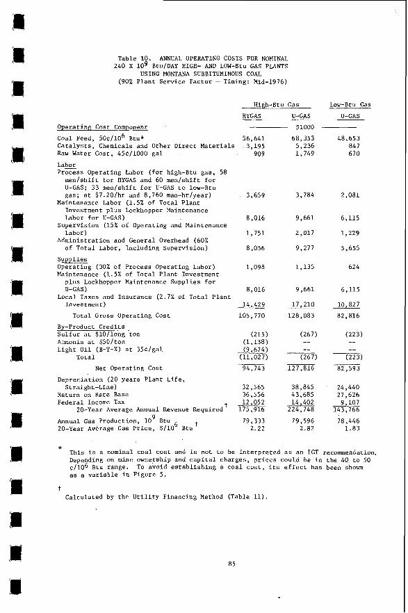
Table 10. ANNUAL OPERATING COSTS FOR NOMINAL 240 X l o 9 Btu/DAY HIGH- AND LOW-Btu GAS PLANTS
USING MONTANA SUBBITUMINOUS COAL (90% P l a n t Serv ice Fac tor - Timing: Mid-1976)
Operat ing Cost Component
High-Btu Gas Low-Btu Cas
HYGAS U-GAS U-GAS - $1000
Coal Feed, 50$/106 Btu* 56,641 Catalysts. Chemicals and Other Di rec t Materials 3,195
~I
Raw Water Cost, 45c/1000 g a l
Labor Process Operat ing Labor ( for high-Btu gas , 58
men/sh i f t f o r HYGAS and 60 men/sh i f t f o r U-GAS; 33 men/shif t f o r U-GAS t o low-Btu gas; a t $7.20/hr and 8,760 man-hr/year)
Investment p l u s Lockhopper Maintenance Labor f o r U-GAS)
Supervis ion (15% of Operat ing and Maintenance Labor)
Adminis t ra t ion and General Overhead (60% of T o t a l Labor, Inc luding Supervis ion)
Maintenance Labor (1.5% of Tota l P l a n t
Suppl ies Operat ing (30% of Process Operat ing Labor) Maintenance (1.5% of T o t a l P lan t Investment
p l u s Lockhopper Maintenance Suppl ies f o r U-GAS)
Local Taxes and Insurance (2.7% of T o t a l P l a n t Inves t men t )
T o t a l Gross Operat ing Cost
By-product C r e d i t s S u l f u r a t $lO/long ton Ammonia a t $50/ ton Light O i l (B-T-X) a t 35C/gal
Net Operat ing Cost
Tota l
Deprec ia t ion (20 y e a r s P l a n t L i f e , S t r a i g h t - l i n e )
Return on Rate Base Federa l Income Tax
Annual Gas Product ion, l o 9 Btu 20-Year Average Gas P r i c e , $ / lo6 Btu'
t 20-Year Average Annual Revenue Required
909
3,659
8,016
1 ,751
8,056
1,098
8,016
14,429
105,770
(215) (1,138) (9,674)
(11,027)
94,743
32,565 36,556 12,052
175,916
79,333 2.22
68,353 5,236 1 ,749
3,784
9 ,661
2,017
9,277
1,135
9,661
17,210
128,083
(267) -- --
(267)
127,816
38,845 43,685 14,402
224,748
79,596 2.82
48,653 84 7 6 70
2,081
6,115
1,229
5,655
624
6,115
10,827
82,816 ___
(223) -- --
(223)
82,593
24,440 27,626
9,107 143,766
78,446 1 .83
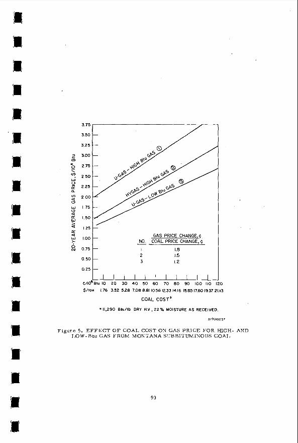
* This i s a nominal c o a l c o s t and i s not t o be i n t e r p r e t e d as an IGT recommendation. Depending on mine ownership and c a p i t a l charges , p r i c e s could be i n the 40 t o 50 $ / lo6 Btu range. as a v a r i a b l e i n F igure 5 .
To avoid e s t a b l i s h i n g a c o a l c o s t , i t s e f f e c t has been shown
t Calculated by t h e U t i l i t y Financing Method (Table 11) .
85
3 m m rl 0
0
+
m m d
d
0 + z
0 0
111: P
U
2 U m 2 d
n
u C
d a d
U
0 U
X
* (0
Y
m x
VI P-
m m rl
x
I1
3 U m
m $4
m h m
U .rl w 0
a
0 0 d . ,n C
.r( u m 4 Y a (0
M
m M
$4
% Y
m h
0 N
V
4
m m h
86
High-Btu Gas Using HYGAS and U-GAS
The c a p i t a l r e q u i r e d f o r t h e HYGAS and t h e u-GAS p l a n t s f o r producing high-Btu gas are $674 m i l l i o n and $805 m i l l i o n (Table 9 ) . Major i t e m s i n both p l a n t s a r e g a s i f i c a t i o n r e a c t o r s , p u r i f i c a t i o n , oxygen supply, and o f f s i t e s . The HYGAS r e a c t o r system Costs more than t h e U-GAS r e a c t o r system because of its g r e a t e r s i z e , com- p l e x i t y , and t h e much h igher opera t ing p r e s s u r e requi red . However, because o f t h e much higher c o s t s f o r oxygen supply, methanat ion, s y n t h e s i s and product gas compres- s i o n , and steam genera t ion f o r t h e s impler U-GAS r e a c t o r , t o t a l c a p i t a l investment f o r t h e U-GAS Process is $131 m i l l i o n more than f o r t h e HYGAS Process .
The c a l c u l a t e d 20-year average g a s p r i c e o f $2.82/106 Btu wheg a U-GAS r e a c t o r i s used f o r SNG i s s b s t a n t i a l l y h igher than t h e p r i c e of $2.22/10 Btu f o r t h e HYGAS Process f o r $0.50/10 Btu c o a l (Table 10). A p r i v a t e i n v e s t o r f inanc ing method (DCF) w a s a l s o developed by t h e FPC t a s k f o r c e comprising 100% e q u i t y c a p i t a l , 25- year p r o j e c t l i f e , 16-year sum-of-the-year's d i g i t s d e p r e c i a t i o n , a n t 12% DCF r a t e of r e t u r n . With t h i s method, t h e gas p r i c e s a r e $3.63 and $2.89/10 Btu f o r the U-GAS and t h e HYGAS Processes . Use of the U-GAC r e a c t o r g i v e s a h i g h e r p r i c e be- cause of l w e r conversion e f f i c i e n c y and high r p l a n t cos t . This p l a n t r e q u i r e s $11.7 X 10 more c o a l and produces $10.8 X 10 fewer by-products compared with t h e HYGAS plan t . The by-products of 65.3 long tons/day s u l f u r , 69.3 tons/day ammonia, a n i 84,144 gal /day l i g h t o i l (B-T-X) reduce t h e HYGAS 1 0 Btu a t t h e u n i t va lues of $lO/long ton s u l f u r , $50/ton ammonia, and $0.35/gal f o r t h e l i g h t o i l . wi th n e g l i g i b l e e f f e c t on gas p r i c e .
I:
8 %
gas p r i c e by about $0.141
There a r e 81.4 l o n g tons/day of s u l f u r by-product f o r U-GAS
Low-Btu Gas by t h e U-GAS Process and I ts Comparison t o High-Btu G a s by t h e HYGAS Process
Table 9 a l s o shows a t o t a l c a p i t a l investment of $674 m i l l i o n f o r t h e HYGAS high-Btu p l a n t and $508 m i l l i o n f o r t h e U-GAS low-Btu p l a n t . The U-GAS oxygen supply c o s t s $90 m i l l i o n , twice t h a t f o r HYGAS. However, a l l o ther a s p e c t s f o r low-Btu gas - c o a l feeding , g a s i f i c a t i o n , product upgrading, and o f f s i t e s - c o s t much less.
Table 1 0 p r e s e n t s annual o p e r a t i n g c o s t s , 20-year average annual revenue re - qu i red , and gas p r i c e . HYGAS c o a l c o s t s a r e $8 mi l l ion /year more than f o r low-Btu U-GAS; c a t a l y s t and chemical c o s t s a r e $2.3 m i l l i o d y e a r more f o r HYGAS. The U-GAS system requi res 25 m e d s h i f t fewer i n o p e r a t i n g labor than t h e HYGAS system. Capi ta l - re la ted c o s t s a r e about $8 m i l l i o n more f o r t h e HYGAS system. The higher HYGAS c o s t s a r e somewhat o f f s e t by t h e $11 m i l l i o n h igher by-product c r e d i t . The t o t a l n e t d i f f e r e n c e i n n e t o p e r a t i o n c o s t 2 i s $12 mi l l ion . t a l and opera t ing cos s l e a d t o a $0.39/10 Btu h igher gas p r i c e f o r HYGAS (HYGAS
The h i g h e r HYGAS capi -
$2.22, U-GAS $1.83/10 6 Btu).
I f gas p r i c e &s c a l c u l a t e d using t h e DCF method descr ibed a ove, t h e U-GAS k p r i c e i s $2.34/10 Btu compared with high-Btu gas a t $2.89/10 Btu.
Comparison of High- and Low-Btu Gas P r i c e S e n s i t i v i t i e s
Figure 4 shows the e f f e c t of v a r i a t i o n s i n p l a n t c o s t on t h e 20-year average gas p r i c e . The e f f e c t of v a r i a t i o n s i n both i n s t a l l e d equipment c o s t and t o t a l c a p i t a l cos t are shown. An increase of about 67% i s added t o t h e i n s t a l l e d equip- ment c o s t by t h e v a r i o u s f a c t o r s used t o a r r i v e a t t o t a l c a p i t a l requi red . For a change of $ 1 m i l l i o n i n i n s t a l l e d equipment c o s t , t h e gas p r i c e v a r i e s by 0.36C/10 B t u ; f o r a similar change i n t o t a l c a p i t a l r e q u i r e d , t h e gas p r i c e changes by
6
87
0.22c/106 Btu, when t h e u t i l i t y f inanc ing method is gsed. Fdr t h e p r i v a t e i n v e s t o r f inanc ing method, t h e numbers a r e 0 . 5 3 ~ and 0.31~/10 Btu. These s e n s i t i v i t y f a c t o r s apply t o a l l t h r e e processes .
F igure 5 shows t h e e f f e c t of varying coa l c o s t s on t h e gas p r i c e . For high-Btu gas , t h e s e n s i t i v i t y i s 1.5c change i n gas p r i c e per 1c change i n c o a l c o s t f o r the HYGAS Process . Because of t h e lower e f f i c i e n c y , t h e s e n s i t i v i t y f o r t h e U-GAS t o SNG process i s 1.8~ change i n gas p r i c e p e r 1C change i n c o a l c o s t . The s e n s i t i v i t y f o r t h e U-GAS t o low-Btu g a s process i s 1.2C change i n gas p r i c e p e r 1~ change i n c o a l c o s t .
CONCLUSIONS
The manufacture of p i p e l i n e - q u a l i t y gas by t h e HYGAS Process shows a d e f i n i t e advantage over i t s manufacture by a s ingle-s tage , lower p r e s s u r e system. Although t h e h y d r o g a s i f i e r i s more complex and opera tes at a much h igher pressure than t h e U-GAS r e a c t o r (1165 vs. 335 p s i g ) , a much g r e a t e r amount of methane is made i n the HYGAS r e a c t o r . This g i v e s l a r g e sav ings i n coa l , oxygen, and upgrading c o s t s , re- s u l t i n g i n a lower gas p r i c e and h igher e f f i c i e n c y .
When a low-Btu f u e l g a s of low methane content is s a t i s f a c t o r y , t h e s impler , low-pressure U-GAS Process shows economic and e f f i c i e n c y advantages.
The r e s u l t s a r e summarized below:
High-Btu Gas Low-Btu Gas
HYGAS U-GAS U-GAS
Tot 1 c a p i t a l r e q u i r e d , 674.0 805.0 508.0 $10' (mid-1976)
6 Gas p r i c e , $/lo Btu, u t i l i t y f inanc ing
2.22 2.82 1.83
Overal l thermal e f f i c i e n c y , % 74.0 58.2 80.8
88
[L W
I v)
a
89
2
0 m N
90
m
91
ltGAS u - G A s H y G A s ~ O 670 770 8: 9 7 l o r 1100 -4.50