13
Revision C ©2013, Palo Alto Networks, Inc. www.paloaltonetworks.com High Availability Failover Optimization Tuning HA Timers PAN-OS 6.0.0

Revision C ©2013, Palo Alto Networks, Inc. www.paloaltonetworks.com
High Availability Failover Optimization Tuning HA Timers PAN-OS 6.0.0

©2013, Palo Alto Networks, Inc. [2]
Contents Overview ................................................................................................................................................................................. 3
Passive Link State Auto Configuration (A/P) ........................................................................................................................ 4 ARP and MAC Considerations ............................................................................................................................................ 4 HA Timer Configuration Considerations ............................................................................................................................. 5
Promotion Hold Time ...................................................................................................................................................... 6 Hello Interval ................................................................................................................................................................... 6 Heartbeat Interval ............................................................................................................................................................ 6 Maximum Number of Flaps ............................................................................................................................................. 6 Preemption Hold Time ..................................................................................................................................................... 6 Monitor Fail Hold Up Time and HA Path Monitor Tuning ............................................................................................. 7 Additional Master Hold Up Time ..................................................................................................................................... 7
Other High Availability Timers ............................................................................................................................................ 7 Control Link (HA1) Monitor Hold Time ......................................................................................................................... 7 HA2 Keep-Alive ............................................................................................................................................................... 8 Tentative Hold Timer ....................................................................................................................................................... 9
Link and Path Monitoring .................................................................................................................................................... 9 Checking High Availability State and Statistics .................................................................................................................. 10 Layer 2 Considerations ...................................................................................................................................................... 11 Summary ............................................................................................................................................................................ 11
Revision History .................................................................................................................................................................... 13

©2013, Palo Alto Networks, Inc. [3]
Overview When deploying Palo Alto Networks firewalls in an HA cluster, there are some considerations that should be taken into account to achieve the most optimal failover times. The total failover time depends on several additional factors as well as the HA timer tuning tips mentioned in this document.
Total Failover Time = Failure Detection + HA Failover + Router Reconvergence
Depending on the HA topology, networking protocols implemented (static vs. dynamic routing protocol), and how the HA tuning parameters and routing reconvergence parameters are configured, the total failover time will vary. The Palo Alto Network firewalls support Active/Passive (A/P) or Active/Active (A/A) configuration of two devices of the same hardware model. The active device continuously synchronizes its configuration and session information with the passive device (in A/P mode) or the Active-Secondary (in A/A mode) using two HA interfaces – HA1 and HA2. In the event of a hardware or software disruption on the active firewall, the passive or active-secondary firewall becomes active automatically without loss of service. The time it takes for the surrounding devices to begin forwarding traffic to the activated passive unit is the bottleneck to achieving optimal failover times. For example, static routes will converge faster than dynamic protocols. This document will concentrate on tuning the HA election timers with L3 deployments and the configuration items related to achieving the shortest HA failover times. It will not consider the surrounding networking components and their convergence tuning options. Note: High availability configuration changes must be made separately on HA peers as they are not synchronized across the HA cluster.
Sample Layer 3 Active/Passive HA Cluster

©2013, Palo Alto Networks, Inc. [4]
Passive Link State Auto Configuration (A/P) An important fact to consider when designing an Active/Passive HA architecture is the traffic forwarding links on the passive device defaults to a “Shutdown” state. In the shutdown state, upstream and downstream devices connected to the passive device will not see a valid path until the passive firewall becomes active. The Passive Link State Auto Configuration feature allows you to bring up the passive device’s traffic forwarding links to reduce the failover time. It does this by bringing the interfaces on the firewall to a “link up” state, but blocks inbound and outbound traffic to the interfaces until the passive unit becomes active. This helps to reduce failover times by eliminating the need to go through port learning and negotiation phases right after a failover to the passive device and can reduce failover times by approximately one to two seconds. The Passive Link State Auto Configuration setting is enabled under Device > High Availability > Election Settings. The Passive Link State defaults to “Shutdown” and should be set to “Auto” to facilitate faster failover times and to force the link status of the neighboring devices to be in the “link up” state. When the Passive Link State is set to “Auto”, the HA device in the “passive” state will not forward traffic or respond to ARP requests.
ARP and MAC Considerations Regardless of which option is selected for the A/P device’s Passive Link State, the passive device is completely silent on the network - it never responds to ARP requests and does not forward traffic. Although the passive firewall is not forwarding traffic, the session state information and dataplane run time state (ARP table, neighbor table, user-ip mappings, etc.) synchronization is taking place in real-time between the active/passive devices over the HA2 link. The HA1 link is used to synchronize configuration and other management plane runtime state information (routing updates, user-group mappings, etc.), as well as communicate HA state via hello messages and heartbeat connectivity checks. In Layer 3 deployments, the passive firewall will use gratuitous ARPs to announce its MAC address when it becomes active after a failover. This allows the surrounding devices to learn the new MAC address of the newly activated firewall and will update their MAC tables. Two gratuitous ARPs are sent immediately when the passive firewall takes over as active and then another eight gratuitous ARPs are sent in one second intervals. In Layer 3 deployments, a Virtual MAC is created from the HA Group ID and the Interface ID and is used in place of the physical interface MAC. For A/P deployments, the same VMAC is used. For A/A deployments where there are two Floating IP addresses (FIP, also known as virtual IPs), a VMAC is created for each floating IP. When one active member in an A/A HA environment fails, its FIP and VMAC are transferred to the peer so services are uninterrupted. For existing sessions, the failed device’s FIP and VMAC are used by the active peer to continue services. For new sessions, the failed device’s FIP and the active peer’s VMAC are used. The illustration that follows demonstrates how a VMAC is formed using the vendor ID, Group ID, and Interface ID. MAC Address Format: 00-1B:17:00:XX:YY Where 00:1B:17 (vendor ID): 00 (fixed): XX (HA Group ID): YY (Interface ID)

©2013, Palo Alto Networks, Inc. [5]
Notice that the Interface ID’s decimal value is represented in hex in the last two digits of the VMAC address.
HA Timer Configuration Considerations Palo Alto Networks firewalls provide multiple HA timer settings that can be used to tune the failover time between HA cluster members. The HA election timers can be configured under the Device > High Availability > Election Settings.
The following chart is an example of default and aggressive HA timer settings. Each of these timers will be discussed in the sections that follow.

©2013, Palo Alto Networks, Inc. [6]
Promotion Hold Time The Promotion Hold Time is the amount of time the passive device (A/P) or active-secondary (A/A) waits when the active device is declared to be down (either because of a loss of hello or heartbeat packets, path monitoring failures, etc.) before switching to the active state. A valid setting for the Promotion Hold Time is between 0 and 60000 ms with a default of 2000 ms. Setting this value to 0 will trigger an immediate switchover when a failure is detected. It is best to configure a short amount of time between the failure of the active unit and when the passive unit takes over. This allows the surrounding devices to stabilize the new transition and state changes. Recommendation: To set a faster failover time, lower the default value from 2000 ms to 500 ms. This can achieve a faster failover time of approximately 1.5 seconds. Note: A physical failure of a monitored link will trigger an immediate failover. Link failures take precedence and override the hold timers. Hello Interval Hello packets are used to inform the other peer of the HA state information and are sent over the HA1 connection (control plane). The Hello Interval timer specifies how often a hello message is sent out to the peer and can be set between 8000 to 60000 ms. The minimum value for the Hello interval is 8000 ms and this is the default value. Missing three hello messages will trigger a failover. Failovers based on hello messages are rare, as the Heartbeat timers are generally set to a more aggressive failover interval. Recommendation: Set the Hello interval to the minimum value of 8000 ms (default). This is a relatively safe setting as the Heartbeat Interval setting is usually set for a more aggressive HA 1 communication failure detection rate. Heartbeat Interval Heartbeat monitoring uses ICMP pings to ensure that the HA1 connection (control plane) between the high availability members is operational. A valid setting for this timer is between 1000 and 60000 ms with a default of 1000 ms on the PA-5000 Series, PA-4000 Series, and PA-3000 Series devices and 2000 ms on the PA-2000 Series, PA-500, and PA-200devices. Missing three consecutive heartbeat messages constitutes a failure condition and triggers a failover event. Recommendation: To set a faster failover time, set this value to 1000 ms. Multiply the time reduction by three to calculate the total failover time saved because three heartbeats need to be missed before a failure is declared. For example, if you reduced the Heartbeat Interval on a PA-2050 from 2000 to 1000 ms, you saved 1000 ms x 3 heartbeat intervals for a total of 3000 ms. Maximum Number of Flaps The Maximum Number of Flaps setting enables you to configure the number of times the firewall can go from an “up state to a down state and back up to an up state” again (a flap) within 15 minutes. The default is 3 flaps within a 15 minute period and the valid settings can be from 0 to 16 flaps. A properly tuned HA deployment should not be experiencing firewall flaps. If you see an abnormal number of firewall flaps, check your link and path monitoring timers to make sure they are not set too aggressively for the network conditions the HA cluster is deployed into. Be aware that aggressive timers in high latency networks or networks with frequent link flapping can cause HA failover false positives. Recommendation: The default setting is 3 and this is sufficient for most implementations and should not need to be changed unless there is an abnormal condition in the network that is causing the firewalls to flap. Increase this value if there are conditions in the network causing an abnormal amount of firewall flapping. Preemption Hold Time The Preemption Hold Time is set in minutes and is used to ensure that the higher priority firewall coming back up from a Suspend or Non-Functional state is kept in a non-active state to allow the surrounding network devices enough time to converge. If the firewall comes back up before the neighboring devices are ready, a black holing situation can occur as the firewall starts to forward traffic before the other devices are ready. Recommendation: The default time of 1 minute should be sufficient in most networking environments. If the network is running a dynamic routing protocol that has its Hello and Dead timers set to relatively high values (a longer convergence time) you may need to increase this value to allow proper convergence.

©2013, Palo Alto Networks, Inc. [7]
Monitor Fail Hold Up Time and HA Path Monitor Tuning The Monitor Fail Hold Up Time is used to determine how long the firewall will remain active following a link or path monitor failure. A valid setting for this timer is between 0 and 60000 ms with a default of 0 ms. This means the firewall will initiate a failover immediately after it detects a link or path monitoring failure. You can use the HA Path Monitor Tuning feature (PAN-OS 5.0.0 and later) to configure the ping interval and the number of ping counts to customize the health monitoring interval for the destination IP address being monitored. The ping interval can be configured between 200 to 60000 ms and the default is 200 ms. The ping count can be set between 3 to 10 and the default is 10 counts. With the default values set, the firewall will wait 2 seconds (200ms x 10 lost pings) before declaring the path monitoring failed if there is no response from the monitored IP address. Note: For virtual wire (vwire) and Layer 2 HA deployments, the HA Path Monitor must have a Source IP address configured. Note: The firewall will ignore any link/path monitoring failures for 60 seconds after it becomes active to help prevent firewall flapping. This is an internal timer and cannot be changed. Recommendation: Leave the Monitor Fail Hold Up Time set to 0 ms and configure the HA Path Monitor values to the desired interval to determine a failed path. For links that exhibit periodic flapping, which are generally congested in nature, or have higher latency, configure the path monitoring value for a longer duration. For fast reliable connections to the monitored IP address, either leave the values configure for 2 second path failure detection or lower for a more aggressive failover. Be careful not to lower the value too much or it may inject false positives and cause the firewall to “flap”. Additional Master Hold Up Time The Additional Master Hold Up Time is only applicable to the active device (A/P) or active-primary device (A/A) and is used to prevent a failover on the master device when both devices detect a link or path failure at the same time. This additional hold up time is added to the Monitor Fail Hold Up Time for the active device. A valid setting for this timer is between 0 and 60000 ms with the default set at 500 ms. Recommendation: Leaving the value at the default of 500 ms should be sufficient for most HA applications. Increasing the value will allow more time between a detected monitor failure and when a failover triggers on the active firewall.
Other High Availability Timers Aside from the High Availability Election Timers, there are several other high availability related timers that are used to control how an HA cluster behaves. Although these timers do not directly affect the failover time, having a good understanding of them will give you a better understanding of how high availability operates.
Control Link (HA1) Monitor Hold Time The HA1 Control Link is a critical Layer 3 connection between the two HA devices. HA1 is used to synchronize the configuration, routing updates, User-ID updates, and other critical control plane attributes. HA1 is also used to perform HA heartbeat checks and communicate HA state information through hello messages. On the PA-3000 Series devices and above, dedicated HA1 interfaces are provided on the management plane and should be used as the Primary HA1 interface. Additional HA1 and HA2 backup interfaces can be configured by using regular dataplane interfaces to provide failover. The Management Interface can also be configured as a “reduced functionality” HA1 backup by enabling the “Heartbeat Backup” option in the Election Settings. The Heartbeat Backup is a special HA1 backup mechanism that is only used to send hello and heartbeat information between the HA devices through the management port—it will not send any HA1 synchronization information. Both HA1 Backup interface and Heartbeat Backup can be used simultaneously to provide backup services for the primary HA1 interface. If HA1 Backup is configured, Heartbeat Backup can be optional.
©2013, Palo Alto Networks, Inc. [8]
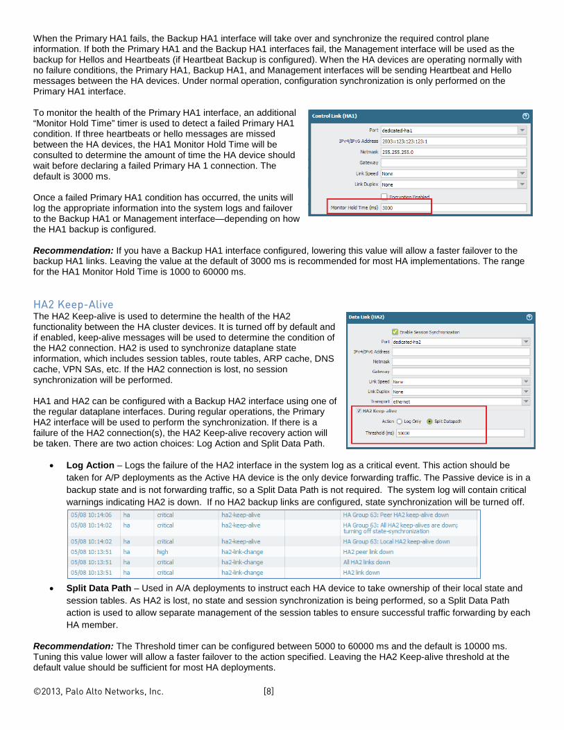
When the Primary HA1 fails, the Backup HA1 interface will take over and synchronize the required control plane information. If both the Primary HA1 and the Backup HA1 interfaces fail, the Management interface will be used as the backup for Hellos and Heartbeats (if Heartbeat Backup is configured). When the HA devices are operating normally with no failure conditions, the Primary HA1, Backup HA1, and Management interfaces will be sending Heartbeat and Hello messages between the HA devices. Under normal operation, configuration synchronization is only performed on the Primary HA1 interface. To monitor the health of the Primary HA1 interface, an additional “Monitor Hold Time” timer is used to detect a failed Primary HA1 condition. If three heartbeats or hello messages are missed between the HA devices, the HA1 Monitor Hold Time will be consulted to determine the amount of time the HA device should wait before declaring a failed Primary HA 1 connection. The default is 3000 ms. Once a failed Primary HA1 condition has occurred, the units will log the appropriate information into the system logs and failover to the Backup HA1 or Management interface—depending on how the HA1 backup is configured. Recommendation: If you have a Backup HA1 interface configured, lowering this value will allow a faster failover to the backup HA1 links. Leaving the value at the default of 3000 ms is recommended for most HA implementations. The range for the HA1 Monitor Hold Time is 1000 to 60000 ms.
HA2 Keep-Alive The HA2 Keep-alive is used to determine the health of the HA2 functionality between the HA cluster devices. It is turned off by default and if enabled, keep-alive messages will be used to determine the condition of the HA2 connection. HA2 is used to synchronize dataplane state information, which includes session tables, route tables, ARP cache, DNS cache, VPN SAs, etc. If the HA2 connection is lost, no session synchronization will be performed. HA1 and HA2 can be configured with a Backup HA2 interface using one of the regular dataplane interfaces. During regular operations, the Primary HA2 interface will be used to perform the synchronization. If there is a failure of the HA2 connection(s), the HA2 Keep-alive recovery action will be taken. There are two action choices: Log Action and Split Data Path.
• Log Action – Logs the failure of the HA2 interface in the system log as a critical event. This action should be taken for A/P deployments as the Active HA device is the only device forwarding traffic. The Passive device is in a backup state and is not forwarding traffic, so a Split Data Path is not required. The system log will contain critical warnings indicating HA2 is down. If no HA2 backup links are configured, state synchronization will be turned off.
• Split Data Path – Used in A/A deployments to instruct each HA device to take ownership of their local state and
session tables. As HA2 is lost, no state and session synchronization is being performed, so a Split Data Path action is used to allow separate management of the session tables to ensure successful traffic forwarding by each HA member.
Recommendation: The Threshold timer can be configured between 5000 to 60000 ms and the default is 10000 ms. Tuning this value lower will allow a faster failover to the action specified. Leaving the HA2 Keep-alive threshold at the default value should be sufficient for most HA deployments.

©2013, Palo Alto Networks, Inc. [9]
Tentative Hold Timer A Tentative State is caused by a link or path monitoring event in an Active/Active HA deployment. The Tentative Hold Timer is only available for A/A HA and is used to keep the firewall in a “tentative” non-forwarding state before allowing it to come back on line as the Active-Secondary firewall. The tentative hold down period ensures that the active-secondary firewall does not come back on line too quickly. If this occurs before the routing tables are fully converged, a black holing situation may occur. A firewall in the tentative state can continue to synchronize information with its peer through the HA1 and HA2 interfaces. It can also continue to process traffic for existing sessions that is being sent to it from a neighboring device by forwarding it to the active peer over the HA3 interface. The active firewall will process the tentative unit’s traffic and will forward it as necessary; the tentative firewall will not forward traffic. Recommendation: The default for this timer is 60 seconds and is a good starting point to use. Tuning this parameter up or down will depend on how quickly adjacencies between neighboring devices can be built and how fast routing tables can be converged. Leaving this timer at the default value or increasing it should not affect the failover time, as the active firewall is still processing traffic. Link and Path Monitoring Implementing Link and Path Monitoring is also a best practice recommendation when trying to optimize failover times. When these options are configured, the loss of a physical link or the failure in monitoring a path beyond the firewall will trigger a switchover from an active state to a non-functional state. The failover time derived by these two types of failures will depend on how the Monitor Hold Up Time and HA Path Monitoring timers are configured. The failover action can be based on failure of ANY link or path, or ALL failures of the links or paths defined within the group. In the link monitoring example shown below, a Link Group is defined to monitor the critical links that make up the WAN, data center, and critical end user networks. The following example uses an “Any” condition that allows failover to occur based on ANY of these links failing.
• A/P HA: Active device becomes non-functional, Passive device takes over as Active • A/A HA: Active-Primary becomes Tentative, Active-Secondary takes over Active-Primary traffic
Path monitoring allows you to
monitor an IP address beyond the firewall and is useful to ensure that the path to a specific destination is reachable. Path monitoring should be used when link monitoring alone is not sufficient and you want to monitor the link(s) beyond the firewall’s physical interface. The following is an example of using Path Monitoring to monitor a specific destination IP addresses using ICMP pings. Path Groups allow you to set up multiple paths to monitor simultaneously and failover can happen on ANY or ALL conditions.

©2013, Palo Alto Networks, Inc. [10]
The Ping Interval can vary between 200 - 60000 ms with a default of 200 ms. The Ping Count can be between 3 and 10 with the default being 10. By tuning these two parameters, you can control how quickly a path monitor failure is detected. Note: Virtual Wire and VLAN path monitoring requires a Source IP address to be configured.
Checking High Availability State and Statistics The CLI is a great way to obtain HA timer status, HA interface statistics, and configuration information. Use the “show high-availability ?” command to see the various HA CLI options.
Some of the most useful high availability statistics to monitor include:
• control-link HA1 statistics • flap-statistics Firewall flap count statistics • ha2-keepalive HA2 keep alive statistics • interface HA interface statistics and status • link-monitoring Link monitoring status • path-monitoring Path monitoring status and statistics • state-synchronization Various HA state synchronization statistics • transactions HA transition statistics for the various HA states
Additional information on HA3 counters can be viewed through the following global counters:
• ha_aa_pktfwd_rcv • ha_aa_pktfwd_xmt

©2013, Palo Alto Networks, Inc. [11]
These two global counters show the number of packets transmitted and received from the HA3 interface(s) and can be used to gauge if HA3 is passing traffic between the HA cluster members. Remember to size the HA3 link accordingly and that link aggregation can be used to trunk up to eight interfaces if required.
Layer 2 Considerations If HA cluster members are connected to Layer 2 switches, as shown in the sample HA topology diagram mentioned previously, you must enable the Spanning Tree Protocol (802.1D) on the Layer 2 switches to prevent possible loops from forming. When Spanning Tree Protocol (STP) is enabled on a switch port, it will not immediately start to forward traffic. Spanning tree will go through a number of states while it determines the topology of the network and this can cause a delay of up to 50 seconds before traffic is forwarded. Since the introduction of spanning tree (1985), there have been significant improvements to the original standard and Rapid Spanning Tree (RSTP – RFC 802.1w) can now significantly reduce the network discovery and loop prevention times down to a few seconds or even sub-second in some cases. In order to provide the fastest possible loop detection, RSTP should be used whenever possible. Refer to the switch manufacturer’s documentation on how to configure RSTP (or equivalent) on the switch ports that the Palo Alto Networks firewalls are connected to. Recommendation: In Layer 2 HA deployments, enable RSTP or equivalent on all switch interfaces that connect to the Palo Alto Networks firewalls. This will help prevent possible Layer 2 loops between the firewall members.
Summary The PAN-OS high availability feature offers flexible deployment options with multiple timers to help tune the failover times. The total failover time to resume traffic forwarding after a failover condition is not only dependent on the HA failover event, but also on how fast routing tables and adjacencies can be formed between neighboring devices. To minimize the impact of a failed Palo Alto Networks firewall in your HA environment, you may need to adjust the HA timers as well as your routing protocol’s convergence parameters to achieve the desired results. Recommendations for achieving optimal HA failover time for a PAN-OS 5.x.x Layer 3 HA cluster can be summarized as follows:
• Set Passive Link State to Auto for Active/Passive HA • Set Promotion Hold Down timer to 500 ms • Set Hello Interval to 8000 ms • Set Heartbeat Interval to 1000 ms • Set the Maximum Flaps to 3 • Set the Preemption Hold Time to 1 minute • Set the Monitor Fail Hold Up Time to 0 ms • Set the Additional Master Hold Up Time to 500ms • Enable and configure Link Monitoring • Enable and configure Path Monitoring • Configure and tune HA Path Monitoring for speed of path failure detection • Enable Tentative Hold Timer for Active/Active HA, start with default value and tune as required

©2013, Palo Alto Networks, Inc. [12]
• Enable HA2 Keep-Alive, start with default value and tune as required • For Layer 2 connections, enable Rapid Spanning Tree (or equivalent) on neighboring switches
Note: These recommendations are starting points only and may need to be fine-tuned further depending on networking conditions and external factors such as dynamic routing protocols and the HA deployment topology.
©2013, Palo Alto Networks, Inc. [13]
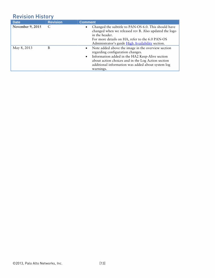
Revision History Date Revision Comment November 9, 2015 C • Changed the subtitle to PAN-OS 6.0. This should have
changed when we released rev B. Also updated the logo in the header. For more details on HA, refer to the 6.0 PAN-OS Administrator’s guide High Availability section.
May 8, 2013 B • Note added above the image in the overview section regarding configuration changes.
• Information added in the HA2 Keep-Alive section about action choices and in the Log Action section additional information was added about system log warnings.


