12
Engineered to Save CHC Series High Capacity Refrigerated Dryer 2,000–20,000 SCFM NEW
Engineered to Save
CHC SeriesHigh Capacity Refrigerated Dryer
2,000–20,000 SCFM
NEW
Custom Designed to Meet Your Needs• Engineered to economically produce consistent dew
points with low pressure drops.
• In-house design allows precision computer matching of air sides and refrigeration systems to your flow, dew point, and pressure drop requirements.
• Several sizings can be computed so that you can evaluate initial costs versus various pressure drop and dew point options.
CHC Series
Give us the operating conditions (Input Data) listed here and allow us to select a heat exchanger set and condensing unit combination that will most efficiently produce the outlet dewpoint and pressure drop you require.
Input DataFlow rate:Compressed air conditions Inlet temperature: Inlet pressure:Required outlet dewpoint:Required pressure drop across dryer:Condenser Cooling Medium: Liquid cooled
Medium ( water, glycol): Temperature:Air-Cooled Min/Max Ambient Air Temperature:
Power requirements: V ph HzGas to be dried: Compressed air, Other (specify)
Output data
Dryer Model:
Capacity @ conditions indicated:
Outlet dewpoint:
Pressure drop:/
1 psi
1 2 3 4 5 psi
CompAir
Market Standard
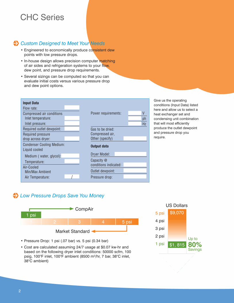
• Pressure Drop: 1 psi (.07 bar) vs. 5 psi (0.34 bar)
• Cost are calculated assuming 24/7 usage at $0.07 kw-hr and based on the following dryer inlet conditions: 50000 scfm, 100 psig, 100°F inlet, 100°F ambient (8500 m³/hr, 7 bar, 38°C inlet, 38°C ambient)
5 psi
4 psi
3 psi
2 psi
1 psi $1, 815Up to
80%Savings
US Dollars
$9,070
Low Pressure Drops Save You Money
2
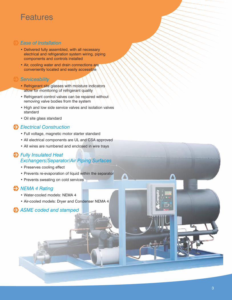
Ease of Installation• Delivered fully assembled, with all necessary
electrical and refrigeration system wiring, piping components and controls installed
• Air, cooling water and drain connections are conveniently located and easily accessible
Serviceability• Refrigerant site glasses with moisture indicators
allow for monitoring of refrigerant quality
• Refrigerant control valves can be repaired without removing valve bodies from the system
• High and low side service valves and isolation valves standard
• Oil site glass standard
Electrical Construction• Full voltage, magnetic motor starter standard
• All electrical components are UL and CSA approved
• All wires are numbered and enclosed in wire trays
Fully Insulated Heat Exchangers/Separator/Air Piping Surfaces• Preserves cooling effect
• Prevents re-evaporation of liquid within the separator
• Prevents sweating on cold services
NEMA 4 Rating• Water-cooled models: NEMA 4
• Air-cooled models: Dryer and Condenser NEMA 4
ASME coded and stamped
Features
3
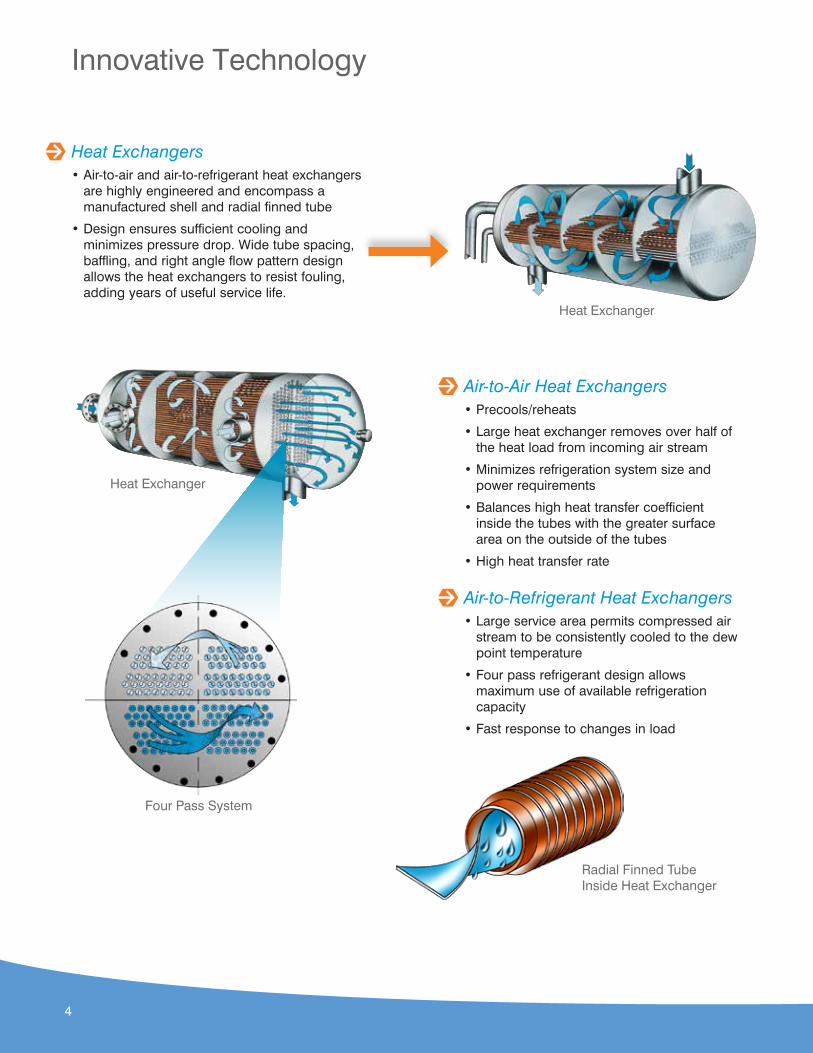
Heat Exchangers• Air-to-air and air-to-refrigerant heat exchangers
are highly engineered and encompass a manufactured shell and radial finned tube
• Design ensures sufficient cooling and minimizes pressure drop. Wide tube spacing, baffling, and right angle flow pattern design allows the heat exchangers to resist fouling, adding years of useful service life.
Innovative Technology
Heat Exchanger
Heat Exchanger
Four Pass System
Radial Finned Tube Inside Heat Exchanger
Air-to-Air Heat Exchangers• Precools/reheats
• Large heat exchanger removes over half of the heat load from incoming air stream
• Minimizes refrigeration system size and power requirements
• Balances high heat transfer coefficient inside the tubes with the greater surface area on the outside of the tubes
• High heat transfer rate
Air-to-Refrigerant Heat Exchangers• Large service area permits compressed air
stream to be consistently cooled to the dew point temperature
• Four pass refrigerant design allows maximum use of available refrigeration capacity
• Fast response to changes in load
4
1
3
4
44
2
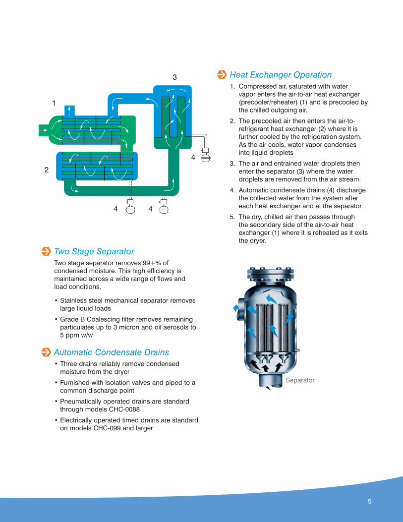
Two Stage SeparatorTwo stage separator removes 99+% of condensed moisture. This high efficiency is maintained across a wide range of flows and load conditions.
• Stainless steel mechanical separator removes large liquid loads
• Grade B Coalescing filter removes remaining particulates up to 3 micron and oil aerosols to 5 ppm w/w
Automatic Condensate Drains• Three drains reliably remove condensed
moisture from the dryer
• Furnished with isolation valves and piped to a common discharge point
• Pneumatically operated drains are standard through models CHC-0088
• Electrically operated timed drains are standard on models CHC-099 and larger
Separator
Heat Exchanger Operation1. Compressed air, saturated with water
vapor enters the air-to-air heat exchanger (precooler/reheater) (1) and is precooled by the chilled outgoing air.
2. The precooled air then enters the air-to-refrigerant heat exchanger (2) where it is further cooled by the refrigeration system. As the air cools, water vapor condenses into liquid droplets
3. The air and entrained water droplets then enter the separator (3) where the water droplets are removed from the air stream.
4. Automatic condensate drains (4) discharge the collected water from the system after each heat exchanger and at the separator.
5. The dry, chilled air then passes through the secondary side of the air-to-air heat exchanger (1) where it is reheated as it exits the dryer.
5
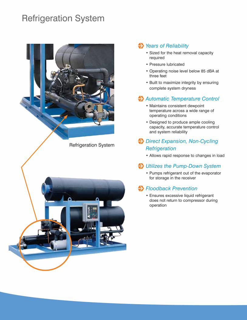
Years of Reliability• Sized for the heat removal capacity
required
• Pressure lubricated
• Operating noise level below 85 dBA at three feet
• Built to maximize integrity by ensuring complete system dryness
Automatic Temperature Control• Maintains consistent dewpoint
temperature across a wide range of operating conditions
• Designed to produce ample cooling capacity, accurate temperature control and system reliability
Direct Expansion, Non-Cycling Refrigeration• Allows rapid response to changes in load
Utilizes the Pump-Down System• Pumps refrigerant out of the evaporator
for storage in the receiver
Floodback Prevention• Ensures excessive liquid refrigerant
does not return to compressor during operation
Refrigeration System
Refrigeration System
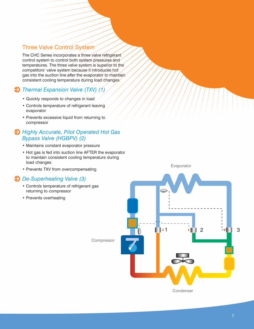
Three Valve Control SystemThe CHC Series incorporates a three valve refrigerant control system to control both system pressures and temperatures. The three valve system is superior to the competitors’ valve system because it introduces hot gas into the suction line after the evaporator to maintain consistent cooling temperature during load changes.
Thermal Expansion Valve (TXV) (1)
• Quickly responds to changes in load
• Controls temperature of refrigerant leaving evaporator
• Prevents excessive liquid from returning to compressor
Highly Accurate, Pilot Operated Hot Gas Bypass Valve (HGBPV) (2)• Maintains constant evaporator pressure
• Hot gas is fed into suction line AFTER the evaporator to maintain consistent cooling temperature during load changes
• Prevents TXV from overcompensating
De-Superheating Valve (3)• Controls temperature of refrigerant gas
returning to compressor
• Prevents overheating
321
Evaporator
Compressor
Condenser
7

19104
58
7
6
2
3
Refrigeration System Operation1. High pressure liquid refrigerant is metered into
the air-to-refrigerant heat exchanger (refrigeration system evaporator) (2) through the thermal expansion valve (1) where it becomes a gas.
2. The low pressure gas then moves through the accumulator (3) and the suction line filter (4) to the refrigeration compressor (5) where it is compressed into a high pressure gas.
3. The high pressure gas moves to an air or water cooled condenser (6) where it gives up heat and condenses into a high pressure liquid. The high pressure liquid travels through the receiver (7) and dryer/filter (8) to the thermal expansion valve (1)
4. A hot gas by-pass valve(10) controls evaporator (2) pressure while a desuperheating valve (9) controls the return gas temperature.
Refrigeration System
8
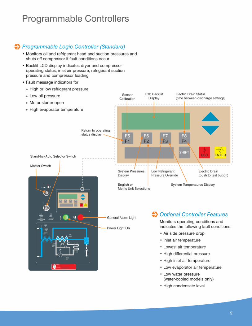
Programmable Logic Controller (Standard)• Monitors oil and refrigerant head and suction pressures and
shuts off compressor if fault conditions occur
• Backlit LCD display indicates dryer and compressor operating status, inlet air pressure, refrigerant suction pressure and compressor loading
• Fault message indicators for:
» High or low refrigerant pressure
» Low oil pressure
» Motor starter open
» High evaporator temperature
Optional Controller FeaturesMonitors operating conditions and indicates the following fault conditions:
• Air side pressure drop
• Inlet air temperature
• Lowest air temperature
• High differential pressure
• High inlet air temperature
• Low evaporator air temperature
• Low water pressure (water-cooled models only)
• High condensate level
I
1 2
O
STANDBY• Modo de Espera
• Attente Standby Mode
AUTO• Modo
Automático• Auto Mode
WARNING: Disconnect the electric power before servicingATTENTION: Déconnecter du circuit d'alimentation eléctrique avant l'entretienPRECAUCION: Desconecte la energía eléctrica antes de realizar cualquier mantenimiento
1 2
F5F1
F6F2
F7F3
F8F4
SHIFTENTERESC
Master Switch
Stand-by / Auto Selector Switch
Power Light On
General Alarm Light
Programmable Controllers
F5F1
F6F2
F7F3
F8F4
SHIFTENTERESC
LCD Back-lit Display
System Pressures Display
Low Refrigerant Pressure Override
Return to operating status display
English or Metric Unit Selections
Electric Drain (push to test button)
Electric Drain Status (time between discharge settings)
System Temperatures Display
Sensor Calibration
9
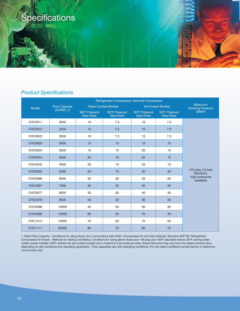
Product Specifications
Model Flow Capacity (SCFM) (1)
Refrigeration Compressor Nominal HorsepowerMaximum
Working Pressure (MWP)
Water-Cooled Models Air-Cooled Models
38°F Pressure Dew Point
50°F Pressure Dew Point
38°F Pressure Dew Point
50°F Pressure Dew Point
CHC0011 2000 10 7.5 10 7.5
175 psig (12 bar) Standard,
high pressures available
CHC0012 2250 10 7.5 10 7.5
CHC0022 2500 10 7.5 15 7.5
CHC0033 3000 15 10 15 10
CHC0034 3500 15 10 20 15
CHC0044 4000 20 10 25 15
CHC0045 4500 25 15 25 15
CHC0055 5000 25 15 30 20
CHC0066 6000 30 20 35 25
CHC0067 7000 35 25 35 25
CHC0077 8000 35 25 40 30
CHC0078 8500 40 30 50 35
CHC0088 10000 40 35 50 35
CHC0099 12000 60 35 70 40
CHC1010 15000 70 50 70 50
CHC1111 20000 80 70 80 70
1. Rated Flow Capacity - Conditions for rating dryers are in accordance with CAGI (Compressed Air and Gas Institute). Standard ADF100: Refrigerated Compressed Air Dryers - Methods for Testing and Rating: Conditions for rating above dryers are: 100 psig and 100°F saturated inlet air, 85°F cooling water (water-cooled models) 100°F ambient air (air-cooled models) and a maximum 5 psi pressure drop. Actual dew point may vary from the stated nominal value depending on site conditions and operating parameters. Flow capacities vary with operating conditions. For non-rated conditions contact factory to determine correct dryer size.
Specifications
10
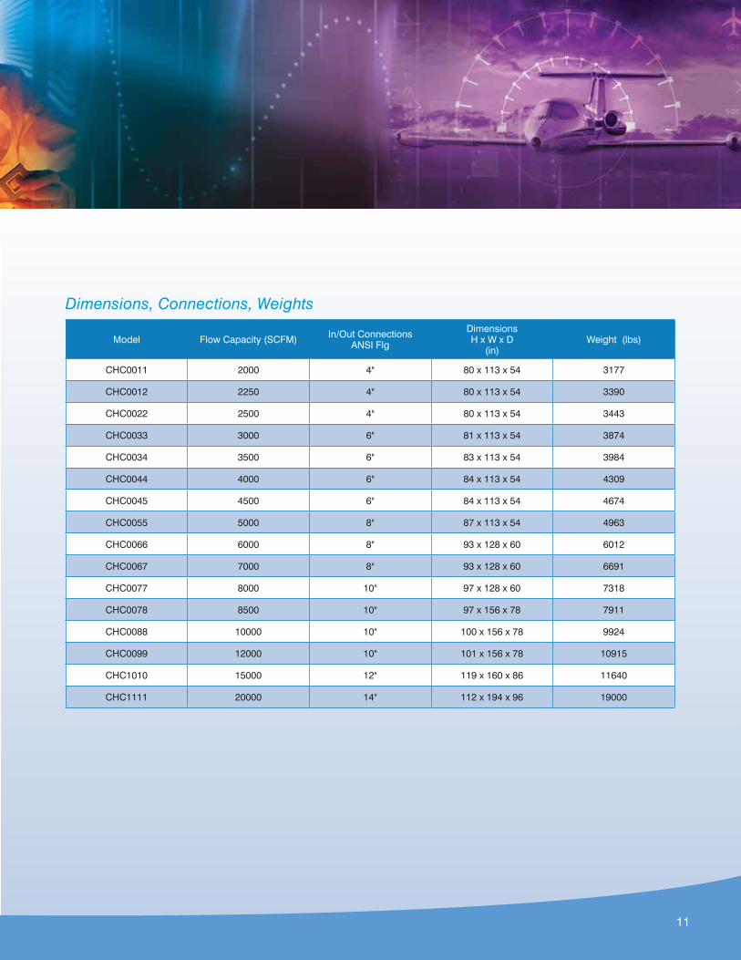
Dimensions, Connections, Weights
Model Flow Capacity (SCFM) In/Out Connections ANSI Flg
DimensionsH x W x D
(in)Weight (lbs)
CHC0011 2000 4" 80 x 113 x 54 3177
CHC0012 2250 4" 80 x 113 x 54 3390
CHC0022 2500 4" 80 x 113 x 54 3443
CHC0033 3000 6" 81 x 113 x 54 3874
CHC0034 3500 6" 83 x 113 x 54 3984
CHC0044 4000 6" 84 x 113 x 54 4309
CHC0045 4500 6" 84 x 113 x 54 4674
CHC0055 5000 8" 87 x 113 x 54 4963
CHC0066 6000 8" 93 x 128 x 60 6012
CHC0067 7000 8" 93 x 128 x 60 6691
CHC0077 8000 10" 97 x 128 x 60 7318
CHC0078 8500 10" 97 x 156 x 78 7911
CHC0088 10000 10" 100 x 156 x 78 9924
CHC0099 12000 10" 101 x 156 x 78 10915
CHC1010 15000 12" 119 x 160 x 86 11640
CHC1111 20000 14" 112 x 194 x 96 19000
11
Protect the Investment in CompAirRegular maintenance and service of CompAir product is critical to the performance and longevity of the equipment. Only CompAir can provide the assurance that the investment will provide a lifetime of productivity.
ReliabilityOnly CompAir can provide aftermarket parts and services that are engineered for use in CompAir products. The parts and lubricant have been tested under rigorous conditions at the factory to the highest quality standards.
PerformanceOnly CompAir can provide aftermarket parts designed specifically for the CompAir product. Use of OEM parts ensures that the investment in CompAir will continue to perform year in and year out with the same reliability and efficiency.
Ease of Doing BusinessOnly CompAir can provide the peace of mind of turning to one supplier and one source for all aftermarket needs. CompAir has the support network in place to handle all customer service, service and technical support needs.
ValueOnly CompAir can provide the high quality aftermarket parts and services for the life of the investment in CompAir. Proper care of the CompAir product is vital to the equipment’s performance and efficiency. Lean on a trusted source—CompAir.
Aftermarket Parts & Lubricants
www.CompAir.com [email protected]
©2011 Gardner Denver, Inc. Printed in U.S.A. CU-AT-CHC 1st Ed. 6/11
®
MemberPlease recycle after use.
CompAir USA 1301 North Euclid Avenue Princeton, IL 61356 United States of AmericaTel (866) 994-8807 Fax (800) 443-7790
CompAir Canada 871 Cranberry Court Oakville, Ontario L6L 6J7 CanadaTel (905) 847-0688 Fax (905) 847-8124
8
ACCREDITED


