Diss. ETH No. 20476 High Efficiency Electrostatic Precipitator Systems with Low Effects on the Mains A dissertation submitted to ETH Zurich for the degree of DOCTOR OF SCIENCES presented by THIAGO BATISTA SOEIRO E.E., M.Sc. Federal University of Santa Catarina born June 3, 1981 citizen of Florianopolis, Brazil accepted on the recommendation of Prof. Dr. Johann W. Kolar, examiner Prof. Dr. Marcelo Heldwein, co-examiner 2012
Transcript
Diss. ETH No. 20476
High Efficiency Electrostatic Precipitator Systems with Low
Effects on the Mains
A dissertation submitted to
ETH Zurich
for the degree of
DOCTOR OF SCIENCES
presented by
THIAGO BATISTA SOEIRO
E.E., M.Sc. Federal University of Santa Catarina
born June 3, 1981
citizen of Florianopolis, Brazil
accepted on the recommendation of
Prof. Dr. Johann W. Kolar, examiner
Prof. Dr. Marcelo Heldwein, co-examiner
2012
For Emma Drinkel with love.
For my mother and father.
i
Acknowledgements
To my parents, Newton Sure Soeiro and Lucidalva de Paula Batista Soeiro,
who provided me with an environment in which I could study and develop my skills. It was due to their constant encouragement, support and dedication that I was able to complete the technical school, my undergraduate degree, my master degree and now, my doctorate in electrical engineering. Besides my life and my health, I owe to them my character; their teaching developed my critical thinking and built my knowledge.
To Professor Johann W. Kolar for the competent guidance, understanding and friendship throughout the duration of my PhD.
To Marcelo Heldwein for accepting the co-examiner invitation and for the technical feedback of my work.
To my PES lab. colleagues, PhD, master and graduate students for the friendship and fun.
To the employees of the PES lab, Peter Seitz, Peter Albrecht, Monica Kohn-Muller, Roswitha Coccia, Prisca Maurantonio, Damaris Egger and also the IT support from Claudi Stucki, as well as all the other people who work to develop and consolidate the PES lab as a world-renowned centre for power electronics.
To ETH Zurich, including all the employees, especially those from the Electrical Engineering and Postgraduate Departments (D-ITET), for the support given. Also, to ALSTOM Sweden and its team of engineering, in special to Alain Bill, Per Ranstad and Jorgen Linner.
To Emma E. Drinkel and her family for the love, support and encouragement during the almost five years of study.
Finally, to all those who contributed directly and indirectly towards the conclusion of this work.
Acknowledgements.
ii
iii
Abstract
HE growing concern about the quality of the environment has led many research laboratories and electricity companies to devote more and more attention to new technologies for the elimination of polluting agents or particles from industrial flue gases.
The usage of more efficient industrial air filters, such as Electrostatic Precipitators (ESPs), has become customary. Advantageously, ESPs have the flexibility of working in wide ranges of gas temperatures and usually have a particle collection efficiency as high as 99 %. They are durable, cost effective, and relatively easy to operate. When compared to fabric filters, their operation costs are low, and the risk of damage and stoppage owing to functional disorders is considerably smaller.
Industrial ESPs are normally divided into several sections or zones in order to increase their collection efficiency. Each of these sections has its own power supply, which is supplied from the three-phase mains and controlled individually, having a typical output power range of 10 kW to 120 kW and an output dc voltage range of 30 kV to 100 kV. These power supplies can have different converter topologies or configurations, depending on their location within the ESP. In outlet zones, for example, pulsed voltages very close to the sparkover limit are used more and more frequently, as they increase the particle collection efficiency. However, this could result in frequent output short circuits causing severe distortions of the mains currents.
Nowadays, the so called “modern ESP power supply” typically employs the three-phase diode bridge rectifier as a front-end converter due to its simplicity, reliability and low cost. The main drawback of this concept is that diode rectifiers inject significant current harmonics into the power system which can cause overloading of nearby shunt capacitors or a distortion of the mains voltage at the point of common coupling. Therefore, simple rectifiers do not meet international guidelines concerning input current harmonics. In addition, in pulse operation mode a drastically unbalanced loading of the mains phases can occurs. Accordingly, the concept employed today bears the risk of causing severe problems such as malfunction of other equipment fed by the same mains, audible noise, increased losses of transformers, generators and power lines, electric
T
Abstract.
iv
resonances in the mains, and mechanical oscillations in generators. Up to now, there have been only a few departures from the use of
traditional mains frequency rectifiers. Instead, the research has been concentrated on the output stage of the ESP’s power supplies (back-end dc-dc converter, i.e. resonant converters). There, cost savings for projects could be achieved due to the smaller dimensional requirements of the precipitator. However, to extract the maximal performance of such a topology, the optimal design of components, for a specific control technique used, is required. Moreover, the evaluation of strategies to increase the system power capability becomes important in order to further shrink the volume and therefore to reduce the total system costs.
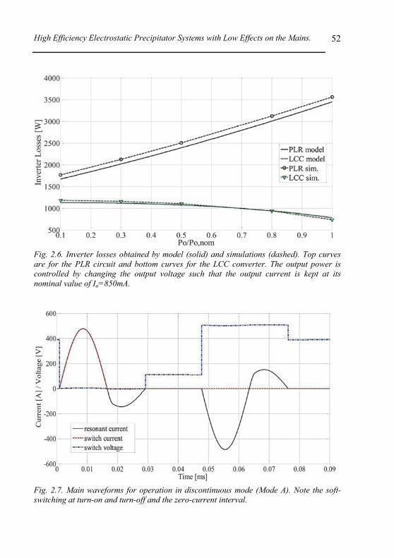
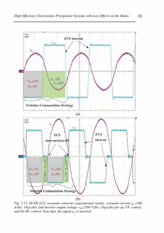
In Chapter 2 the series parallel resonant converter, referred here to as LCC resonant converter, with capacitive output filter is identified as an advantageous solution for the back-end of the ESP power supplies. An automated design optimization procedure for the LCC circuit, which reduces the design effort significantly, particularly during the initial design phases, is proposed. Requisites necessary for the optimal design of this system and means to derive its accurate mathematical model, such as the power loss from commercial IGBTs, resulting in high power density and lower circuit component stresses, are described.
In Chapter 3, in order to improve the mains power quality of an ESP system, the influence of the multiple three-phase power supplies of an ESP on the total mains current is studied in detail. The research in general aims for a better understanding of the interaction between the modern ESP power supplies and the mains with special attention to pulsed operation. For this, a time domain sampled-data model of a group of power supplies is established in order to predict the line current harmonics a system generates based on the pulse parameters of each unit. Finally, a simple control strategy to solve the inherent problems caused by the pulsed operation is proposed. The main idea is to arrange the pulses of the individual power supplies in an optimal sequence, so that the group of pulsed power supplies has similar line behaviour to that of an equivalent single power supply operating in continuous mode.
New topological arrangements of groups of power supplies inherently correcting any imbalance caused by the ESP’s operation modes are proposed in Chapter 1. A remarkable solution to improve the line power quality in ESP applications by using both the characteristics of its electrical installation and the typical ESP high power supply is identified and further analysed in Chapter 4. A multi-pulse system can be built by selecting a combination of suitable voltage step-down transformers, preserving the simplicity and reliability of the typical ESP installation which employs three-phase diode bridge rectifiers. In addition, processing only about 10% of the total system apparent power, shunt active filters (AFs) can be placed on the low voltage side of the transformer (LV) for high order harmonic-current-mitigation (>7th harmonic).
In Chapter 5, for an alternative replacement of the three-phase diode
High Efficiency Electrostatic Precipitator Systems with Low Effects on the Mains.
v
bridge rectifiers, the characteristics of multi-pulse and PWM rectifier topologies described in the literature and of new concepts including hybrid systems comprising passive, and active rectifiers and/or active filters are comprehensively evaluated in order to identify a suitable topology for ESP applications. The three-phase 3-level 6-switch VIENNA rectifier, further evaluated in Appendix A, is finally identified as advantageous choice for an ESP power supply, because of its low semiconductor losses and the low rated power of the inductive components.
Abstract.
vi
vii
Kurzfassung
EUE Technologien zur Reinigung industrieller Abgase von umwelt-schädlichen Partikeln rücken aufgrund des wachsenden Umweltbe-wusstseins der Gesellschaft in den Fokus von Energieversorgungsunternehmen und Forschungseinrichtungen.
Hierfür werden typischerweise elektrostatische Abscheider (Electrostatic Precipitators, ESP) verwendet, welche über einen weiten Temperaturbereich eingesetzt werden können und eine Filtereffizienz von über 99% aufweisen. ESPs sind robust, kostengünstig und relativ einfach zu betreiben. Im Vergleich zu Faser/Gewebefiltern sind die Unterhaltskosten geringer; auch die Ausfallswahrscheinlichkeit (Produktionsunterbrüche) ist wesentlich kleiner.
Typischerweise werden ESPs in mehrere Abschnitte oder Zonen unterteilt um die Filterwirkung zu erhöhen. Jeder dieser Abschnitte hat eine eigenständige Energieversorgung, welche aus dem Dreiphasennetz versorgft und individuell geregelt wird. Übliche Ausgangsleistungen sind 10 kW bis 120 kW bei einer Ausgangsspannung von 30 kVDC bis 100 kVDC. Die Netzgeräte innerhalb einer Anlage können, abhängig von der verwendeten Filterzone, unterschiedliche Konvertertopologien aufweisen. In der Nähe des Abzugs werden beispielsweise gepulste Spannungen nahe der Überschlagsgrenze verwendet, welche die Filterwirkung verbessern. Dies führt jedoch zu häufig auftretenden Kurzschlüssen am Lastausgang, welche starke Störungen in den Netzströmen verursachen.
Aufgrund der relativ geringen Kosten, der hohen Robustheit und einfachen Bauweise verwenden die heute gebräuchlichen “modernen” ESP Netzteile üblicherweise dreiphasige Diodengleichrichter als Eingangsstufe. Der grösste Nachteil dieses Ansatzes ist, dass Diodengleichrichter starke Stromoberschwingungen in das Netz einprägen, welche zur Überlastung von Kondensatoren zur Blindleistungskompensation oder generell zu Störungen in den Netzspannungen führen können. Internationale Normen betreffend die Einspeisung von Stromoberschwingungen in das Netz werden von einfachen Diodengleichrichtern nicht erfüllt. Zusätzlich kann durch die gepulste Arbeitsweise von ESP Systemen eine stark asymmetrisch Belastung der drei Netzphasen auftreten. Demzufolge birgt das heute gebräuchliche Konzept das
N
Kurzfassung.
viii
Risiko von Fehlfunktionen benachbarter elektrischer Anlagen, die durch dasselbe Netz gespeist werden. Weitere Nachteile sind erhöhte Verluste in Transformatoren, Generatoren und den Netzleitungen sowie Lärmbelästigungen, Resonanzen im Netz oder mechanische Schwingungen in Generatoren.
Bisher gab es nur sehr wenige Ansätze welche vom konventionellen Gleichrichter abweichen. Die Forschung hat sich viel mehr auf die Ausgangsstufe der ESP Spannungsversorgung konzentriert (DC-DC-Konverter, z.B. Resonanzkonverter). Hiermit können Kosteneinsparungen erzielt werden, wenn die Energieversorgung des Abscheiders geringere geometrische Abmessungen aufweist. Um das Potential solcher Topologien optimal auszunutzen, muss die Wahl der Bauelemente mit dem Regelungsverfahren abgestimmt werden. Ausserdem wird für eine weitere Verkleinerung des Bauvolumens, und damit verbunden der Systemkosten, eine Beurteilung der verschiedenen Möglichkeiten zur Leistungssteigerung des Systems benötigt.
In Kapitel 2 wird der Serienparallel-Resonanzkonverter (LCC Konverter) mit kapazitivem Ausgangsfilter als eine mögliche Lösung für die Realisierung der ESP Endstufe vorgestellt. Eine automatisierte Prozedur zur Designoptimierung des LCC Konverters wird gezeigt, welche den Aufwand des Systementwurfs wesentlich verringert. Diese Vorgehensweise ist insbesondere zu Beginn des Designprozesses hilfreich. Die Voraussetzungen welche für ein optimales Design nötig sind, sowie die Herleitung eines genauen mathematischen Modells, das die Verlustleistungen von IGBTs berücksichtigt, werden im Detail beschrieben.
In Kapitel 3 wird der Einfluss der zuvor besprochenen dreiphasigen Konverter auf die Netzströme im Detail untersucht, um die Einhaltung der erforderlichen Netzqualität sicherzustellen. Die Forschung konzentriert sich hierbei auf ein besseres Verständnis der Interaktion zwischen den ESP Energieversorgungen und dem Netz. Hierbei wird nicht nur jeder Konverter für sich betrachtet, sondern auch das Gesamtsystem mehrerer Konverter eines ESPs. Zu berücksichtigen ist insbesondere die gepulste Arbeitsweise der Konverter. Deshalb wird ein diskretes Zeitbereichsmodell entwickelt. Abhängig von den Pulsparametern jeder Versorgungseinheit können damit die vom System ins Netz injizierten Stromoberschwingungen berechnet werden. Abschliessend wird eine einfache Strategie vorgestellt, die es erlaubt die Probleme zu verringern, welche durch die gepulste Arbeitsweise der ESP Einheiten verursacht werden. Die zugrundeliegende Idee hierfür ist, die Pulse der verschiedenen Einheiten im ESP in einer optimalen Sequenz anzuordnen, so dass sich das Gesamtsystem im Bezug auf das Netz ähnlich einem äquivalenten einzelnen Konverter verhält, der im kontinuierlichen Betrieb arbeitet.
In Kapitel 1 werden neue Anordnungen von Konvertergruppen untersucht, welche die Eigenschaft besitzen die Asymmetrien, die durch den ESP-Betrieb verursacht werden, auszugleichen. Eine bemerkenswerte Lösung um die Netzqualität in ESP-Anwendungen zu verbessern ist, sowohl die Eigenschaften
High Efficiency Electrostatic Precipitator Systems with Low Effects on the Mains.
ix
der elektrischen Installation als auch die Charakteristik der ESP Hochspannungsversorgung auszunutzen. Dies wird in Kapitel 4 ausführlicher untersucht. Ein Mehrpuls-System kann durch die Wahl einer Kombination von Mittel-/Niederspannungstransformatoren aufgebaut werden, wobei die Robust-heit und einfache Struktur der ESP Anordnung mit Dioden-Brückengleichrichter beibehalten wird. Zusätzlich können Aktive Shunt-Filter (AF) auf der Nieder-spannungsseite der Transformatoren angebracht werden, die lediglich eine Bauleistung von 10% der gesamten Systemleistung aufweisen. Dadurch können Oberschwingungen mit einer Frequenz höher als die 7-fache Grundschwingungsfrequenz gedämpft werden.
In Kapitel 5 werden Alternativen zum dreiphasigen Diodengleichrichter ausführlich diskutiert, um die am besten geeignete Topologie für ESP-Anwendungen zu finden. Dabei werden die Eigenschaften von Mehrpuls- und PWM-Gleichrichtertopologien, wie sie aus der Literatur bekannt sind, diskutiert. Ausserdem werden neue Konzepte wie z.B. ein hybrides System mit passivem und aktivem Gleichrichter in Kombination mit aktiven Filtern vorgestellt.
Abschliessend wird in Apendix A der Vienna 6-Schalter Pulsgleichrichter vorgestellt. Aufgrund geringer Schaltverluste und geringer Anforderungen an die induktiven Komponenten ist dieses System für ESP Anwendungen besonders geeignet.
1.3 ESP Power Supply Technologies 6 1.3.1 Conventional Mains Frequency Power Supply (TR) ........................................ 6 1.3.2 High Frequency ESP Power Supply (HFPS) .................................................... 8
1.5 HFPS and the Line Power Quality 15 1.5.1 Harmonic Effects on Mains Installation Components ..................................... 18 1.5.2 Costs and Benefits of Scheduling Optimization .............................................. 22
1.6 Pulsed ESP Systems with Improved Line Power Quality 23 1.6.1 ESP System Employing Multi-Pulse Solution ................................................ 23 1.6.2 ESP System Employing Active Rectifiers ...................................................... 29 1.6.3 ESP Systems Employing Active and Passive Rectifier ................................... 29 1.6.4 ESP System Employing Shunt Active Filter Solution .................................... 33 1.6.5 ESP System Employing Shunt Active Filter and Multi-Pulse Solution .......... 33 1.6.6 Dc Distribution System ................................................................................... 35
1.7 Motivations, Objectives and Contributions of the Work 40
1.8 Publication Overview 43
2. High Efficiency ESP Power Supply: Back-End Converter 45
2.1 High Frequency ESP Power Supply Technology 46 2.1.1 ESP Power Supply Based on Resonant Converters ........................................ 46 2.1.2 LCC Resonant Converter Operating Modes ................................................... 50 2.1.3 Control Strategies for LCC Circuit Operating Above Resonance ................... 56
Contents.
xii
2.2 LCC Converter: Loss Prediction Model 60 2.2.1 Semiconductors Loss Prediction Model ......................................................... 60 2.2.2 Resonant Capacitors Power Loss Model ........................................................ 66 2.2.3 High Frequency Transformer and Series Inductance Models ........................ 66 2.2.4 LCC Resonant Converter: Modified First Harmonic Mathematical Model ... 67 2.2.5 PLR Converter: Modified First Harmonic Mathematical Model ................... 72
2.3 Optimum Design of LCC Converters for ESPs 73 2.3.1 Design Procedure ........................................................................................... 74 2.3.2 Optimization Strategy Based on Genetic Algorithms .................................... 76 2.3.3 Optimization Example ................................................................................... 78
2.4 Experimental Verification 80
2.5 Conclusions 82
3. Method to Improve the Line Power Quality of Pulsed ESPs 85
3.1 Line Current Prediction for Pulsed ESP Systems 85
4. ESP System Employing Multi-Pulse Transformer and Active Filters 103
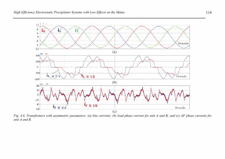
4.1 Multi-Pulse and Active Filter ESP System 103 4.1.1 Multi-Pulse Transformer Current Model ......................................................106 4.1.2 ESP System Performance Analysis ...............................................................111
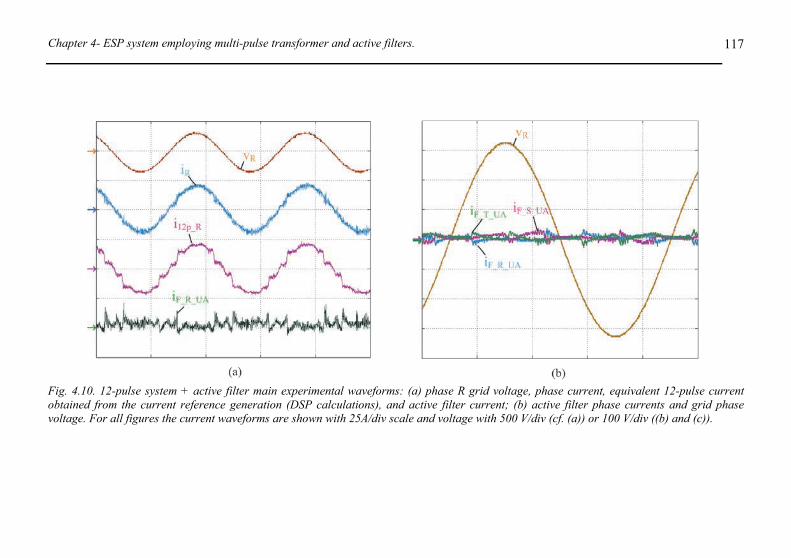
4.2 Experimental Verification 111
4.3 Conclusions 121
5. Electrostatic Precipitator Power Supplies with Low Effects on the Mains 123
5.1 ESP Back-End Power Supply 124
5.2 ESP Systems with Improved Line Power Quality 125 5.2.1 ESP System Employing Multi-Pulse Solution ..............................................125 5.2.2 ESP System Employing Shunt Active Filter .................................................131 5.2.3 ESP System Employing PWM Rectifiers .....................................................131 5.2.4 ESP Systems Employing Hybrid Rectifiers ..................................................141
5.3 Comparative Evaluation 149 5.3.1 Chip Area Based Comparison and Discussion ..............................................162
5.4 Conclusions 163
High Efficiency Electrostatic Precipitator Systems with Low Effects on the Mains.
xiii
6. Conclusion and Future Work 165
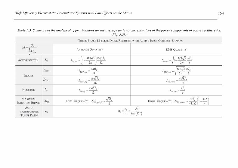
Appendix A. Design of a High Power Active Rectifier for Electrostatic Precipitators 169
A.1 3-Level VIENNA Rectifier Technology 169
A.2 System Operation 171
A.3 120 kW Rectifier Unit Design 177 A.3.1 Control Structure .......................................................................................... 178 A.3.2 Dimensioning the 120 kW VIENNA Rectifier ............................................. 181
A.4 120kW VIENNA Rectifier Prototype for ESPs 183
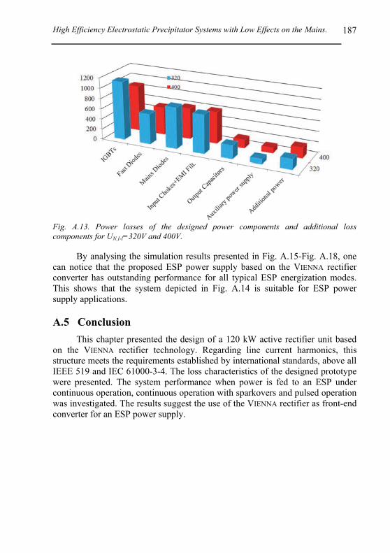
A.5 Conclusion 187
Bibliography 193
Curriculum Vitae 201
Contents.
xiv
1
1. Principles of Electrostatic Precipitation
HE growing concern about the quality of the environment has led many research laboratories and electricity companies to devote more and more attention to new technologies for the removal of polluting agents from industrial flue gases.
Electric power plants, industrial boilers, and other industrial processes generate particles, acid gases and toxic materials that are often harmful to the environment [1]. Particle matter, such as trace metals, can remain suspended in the air for an extended period presenting a potential health hazard. These particles also tend to settle on surfaces such as buildings, machinery, or curtains, where they can cause unsightly blemishes or other problems [2]-[10].
In order to prevent the negative impacts to the environment, and also to reduce CO2 emission, most countries have imposed strict legal boundaries to atmospheric pollution. In Switzerland, for example, emissions of suspended matter are limited to a yearly average value in the range of 40 to 60 mgm-3 for coal or wood furnaces with the actual value depending on the mode of operation and fuel type [8]. These values are valid as of 2011.
Electrostatic Precipitators (ESPs) are the most common industrial devices for particle emission control. These devices display the flexibility of working in wide ranges of gas temperatures and usually have collection efficiencies as high as 99 %. Particles in carrier gas entering the ESP are separated with an electrostatic charge. An ion field generated by high-voltage corona charges the particles, which migrate and are accumulated on grounded plates. The plates are cleaned via rapping, in dry ESPs, or by washing, in wet ESPs, or by both methods in hybrid ESPs. ESPs are durable, cost effective, and relatively easy to operate. When compared to fabric filters, their operation costs are low and the risk of damage and stoppage owing to functional disorders is considerably smaller [4].
This chapter gives an overview of the functionality of the electrostatic precipitator (ESP) itself. For an in-depth description of ESP physics the reader is referred to the books by Parker [5] and [6] or to the article by Mizuno [7], the latter giving a more condensed overview.
Additionally, in this chapter a comparison between conventional mains frequency energization of ESP bus sections and high-frequency power supplies is carried out. First, a brief description of each of the two methods is given and then the respective advantages and disadvantages regarding different technical and
T
Chapter 1 – Principles of Electrostatic Precipitation.
2
economical aspects are compared. The interaction between the mains and a group of high-frequency power supplies feeding an ESP system is investigated, and means for improving the line power quality are proposed. Finally, the contributions of this work for ESP applications are described.
The author would like to thank Jonas Huber for the contribution in the review study related to the ESP applications. The work performed by J. Huber was previously published as an “ETHZ Semesterarbeit” thesis under supervision of the author of this thesis in [8].
1.1 History of Electrostatic Precipitators
In 1824 it was shown by Hohlfeld that particles can be separated from smoke by the application of an electric field. However, the first commercial application of an ESP was carried out by Professor Cottrell from the University of California in 1908 [8]. Fig. 1.1 shows a drawing of the proposed ESP published in the patent ''Art of separating suspended particles from gaseous bodies'' [11], where the ESP was used to reduce sulphuric acid emissions from nearby plants. Around the same time, Lodge performed experiments in Great Britain with valves to be used as rectification devices for ESP energization [6].
It has to be noted that in this early applications the goal was, above all, only to reduce the worst effects of air pollution as no emission limits were set [6]. Besides that, the value of the recovered material was the major factor in determining the cost-effective size of a precipitator. Thus, the collection efficiencies were around 95% which is, although remarkable, not quite as high as nowadays; [5] and [6].
Other means to generate the dc voltage were in use until they were finally made obsolete by the invention of silicon rectifiers in the 1960s [8]. This invention also provided the basis for the silicon controlled rectifiers (thyristors) that are, up to now, used in the majority of ESP power supplies in combination with automatic voltage control. This arrangement, together with a voltage step-up transformer and high-voltage rectification, became the ''standard'' power supply for electrostatic precipitators [6]. They are commonly referred to as ''transformer-rectifier sets'' (TR).
The development of high-voltage high- frequency power supplies (HFPS) for use in ESP applications started in the mid 90’s [12]. High-frequency power supplies have significant advantages over conventional mains-frequency energization. The high switching frequency operation allows for comparatively small overall size and low weight which simplifies the installation of equipment. More importantly, the high switching frequency also leads to a very smooth dc output voltage with negligible ripple and thus higher power in-feed to the precipitator, which generally results in higher collection efficiency [12]. Another effect is the much faster control response that can be achieved. This leads to faster sparkover handling and hence also increases the efficiency, while reducing
High Efficiency Electrostatic Precipitator Systems with Low Effects on the Mains.
3
the stress on the ESP electrodes. In Section 1.3 and 1.4 a more detailed comparison between conventional and high-frequency ESP energization is given.
Fig. 1.1. Sketch of Cottrell's electrostatic precipitator as found in the patent [11].
1.2 Electrostatic Precipitator Technology
Because the collection efficiency of electrostatic precipitators is very high (> 99%), while at the same time the pressure drop between inlet and outlet is small (approx. 1 mbar) and because a wide range of particle sizes, even sub-micrometer particles, can be precipitated, ESPs have a very wide application range [8]. They are mainly used in the power generation sector, where huge gas flows have to be filtered as well as in indoor air cleaning appliances, for example in hospitals [7]. In [6], Parker provides a whole list of industries on whose processes ESPs can be applied, i.e. steam raising, iron and steel production, metallurgical process plants, coal and gas operations, cement and lime
Chapter 1 – Principles of Electrostatic Precipitation.
4
fabrication, waste incineration, pulp and paper manufacture, chemical processing and production as well as ''clean-room'' applications.
It can thus be seen that the application range of electrostatic precipitation is indeed very broad. This and the aforementioned efforts to reduce air pollution show that the operation of the ESP and its power supply system, for example to further reduce energy consumption of the precipitators while maintaining or even improving collection efficiency, are of high importance [8].
1.2.1 ESP Operating Principles
In an ESP the particles are collected by first charging them by means of a corona current and then moving them to one of the electrodes using the Coulomb forces [8]. Parker [6] dissects the process in five basic blocks. First, ions have to be produced through a corona discharge on the so-called ''discharge electrode'', which has usually a high curvature, i.e. some sort of wire, and is normally (except for indoor applications, because of higher ozone production [7]) on negative potential. This is done because in wire-plate configurations the corona-onset voltage is lower and the breakdown voltage is higher when the sharp electrode is on the negative potential [13]. The corona discharge creates ions that move towards the flat and grounded collector plates. On their drift they attach to particles in the gas flow and thus charge those particles. The Coulomb force moves the charged particles towards the collection electrodes as well, where they build up as a layer of dust. This layer is periodically removed from the electrodes through rapping and then collected in hoppers. Fig. 1.2 gives a schematic overview of the process.
Fig. 1.2. Basic operation principle of electrostatic precipitators [4].
High Efficiency Electrostatic Precipitator Systems with Low Effects on the Mains.
5
1.2.2 Collection Efficiency
The charged dust particles are accelerated towards the collecting electrode by means of the Coulomb force within the electric field. According to the equation of motion, they reach a theoretical migration velocity that is dependent on the particle size [6]. For comparatively large particles, that is, greater than 2 µm in diameter, the migration velocity is proportional to the electric field strength squared. For smaller particles the relationship is only linear. The so-called ''Deutsch'' equation states that a higher migration velocity leads to higher collection efficiency. However, it is actually influenced by many factors such as electrode geometry and properties of dust particles [7]. It is also important to take into account that the effective migration velocity within a precipitator is not equal to the theoretical migration velocity that can be calculated. Thus, there is empiricism involved in modification of the original ''Deutsch'' equation in order to obtain more precise tools for the dimensioning of ESPs [6].
From the power supply point of view, however, it can be stated that in general the collection efficiency is proportional to the applied voltage, VESP, squared and the precipitator current IESP [7],
2ESP ESPV I . (1.1)
In order to obtain higher collection efficiencies it is important to operate the precipitator at a voltage as high as possible and also to provide enough power to drive a sufficiently high corona current.
1.2.3 ESP Energization Modes
The waveform of the output voltage can be adjusted in order to cope with different operating conditions in the precipitator. According to Parker [6], three modes, mainly differing in the degree of intermittence, are commonly used.
• Continuous Mode: The average precipitator voltage is as high as possible without triggering “sparkovers” too often. Sparkovers are the breakdown of the dielectric strength of the flowing gas which results in short-circuiting the ESP plates. Higher average voltage and higher corona current normally result in higher collection efficiency. This mode is suitable for collecting coarse dust, i.e. containing particles which are not too small and having rather low resistivity (<1010 Ωcm) [14].
• Intermittent Mode: Considering mains frequency energization, the power supply output is turned off for several cycles before it is turned on again for one (or possibly several) cycles. There are two benefits associated with intermittent energization mode. Firstly, the energy consumption can be lowered without reducing the peak voltage that is applied to the precipitator. Secondly, it can help to reduce problems in back-corona (also called reverse-ionization) conditions that arise when high-resistivity dust is processed [6].
Chapter 1 – Principles of Electrostatic Precipitation.
6
• Pulsed Mode: When the resistivity of the dust is very high (>1012 Ωcm), particle charging and consequently the migration velocity can be significantly improved by the application of short (some ten µs) high-voltage pulses [14]. These pulses can be superimposed on a reduced continuous dc voltage that is still a sufficient driving force for moving the charged particles to the discharge electrodes [6].
1.2.4 Electrical Characteristics and Equivalent Circuit
An electrostatic precipitator can be represented in a simplified manner by an electrical equivalent circuit as shown in Fig. 1.3. The ESP is a highly capacitive load (10 nF to 200 nF). When the corona-onset voltage VCO, represented by the Zener diode, is reached, corona current flow starts. It is governed by a flat non-linear V/I-relationship which is represented by the non-linear resistor. Additionally, the output is short-circuited at random time intervals due to sparkovers in the precipitator [4]. The V/I characteristic of the precipitator is rather flat which means that by increasing the voltage the corona current can be increased disproportionally [15].
For the analyses of single operating points of an ESP power supply this equivalent circuit can be reduced to a simple RC parallel circuit [16]. The value of the resistor then determines the corona current input and therefore for a given output voltage the power that has to be delivered by the power supply.
Fig. 1.3. Equivalent circuit of an ESP as described in [4].
1.3 ESP Power Supply Technologies
1.3.1 Conventional Mains Frequency Power Supply (TR)
Today, in most industrial applications conventional mains frequency power supplies are still the most common practice for ESP energization [4]. Fig. 1.4 shows the basic circuit of such a conventional mains frequency high-voltage power supply (TR).
High Efficiency Electrostatic Precipitator Systems with Low Effects on the Mains.
7
Fig. 1.4. Typical thyristor based mains frequency power supply (TR).
Fig. 1.5. Basic circuit of a high-frequency ESP power supply based on resonant converters.
TR power supplies are connected to a single-phase mains and the high dc
voltage is generated by a full-bridge diode rectifier that is connected to the secondary side of a voltage step-up low frequency transformer with high turns ratio n. The transformer is operated at a frequency of 50 Hz or 60 Hz. The output voltage can be controlled by changing the firing angles of two anti-parallel thyristors at the circuit input [6], [12] and [14].
A series inductor is used mainly to limit current surges that occur during sparkovers in the precipitator. Parker [6] reports another advantage of the inductor, namely a less distinct precipitator current peak and thus a lower form factor of the precipitator current which in turn leads to a lower primary current and consequently lowers reactive power consumption.
To ensure that the output of the power supply matches the operating conditions of the ESP, the power flow is controlled via the firing angles of the two thyristors. An automatic voltage control (AVC) unit is usually employed to calculate these angles for each half cycle of the mains voltage. The necessary measurements can be done either on the primary or secondary side of the transformer, the latter being the typical solution. An AVC system should also implement functionality like sparkover and back-corona detections in order to
iESP
Chapter 1 – Principles of Electrostatic Precipitation.
8
handle such situations correctly [6].
1.3.2 High Frequency ESP Power Supply (HFPS)
A high-frequency ESP power supply consists fundamentally of three stages: an input rectification feeding a dc-link, a high-frequency (HF) inverter, and a high-voltage (HV) high-frequency transformer with secondary side rectification. An example of this circuit is depicted in Fig. 1.5.
The input rectifier is connected to all three phases and may be either passive with a mains side filtering network or active to achieve nearly unity power factor operation if desired [6]. Together with the dc-link capacitor it provides a very smooth dc voltage for the following HF inverter stage. A list of suitable solutions of active rectifiers for ESP applications is given in Chapter 5. From there, a remarkable solution for ESPs is identified and its design for a 120 kW power capability system is presented in Appendix A.
The switching frequency of the HF inverter is typically chosen above 20 kHz, for example Ranstad [12] used already 50 kHz in 1995. The HV transformer is consequently operated at a frequency much higher than the mains frequency. The transformer design differs therefore from that of low frequency transformers; especially parasitic effects have to be considered [6]. The transformer's high-frequency high-voltage output is then rectified with a full-bridge rectifier in a similar way to the conventional power supply. The ESP capacitance serves as filter capacitance for smoothing the ripple of the rectifier output voltage. Because of the high switching frequency the filtering provided by this capacitance is good enough to make the precipitator voltage a nearly constant dc quantity [14].
Resonant converters are an attractive choice for a HFPS because they can operate in soft-switching modes, reducing the switching losses and can incorporate the transformer non-idealities. If a conventional hard-switching PWM converter would be used, the leakage inductance and the secondary winding capacitance of the transformer in particular, would cause parasitic resonances that affect the converter’s behaviour. The analysis and design of resonant converters for ESP applications is presented in Chapter 2.
1.4 TR vs. HFPS
As presented by Kirsten and Karlsson [17], conventional mains frequency power supplies have many drawbacks that can be addressed by using high-frequency power supplies. The improved technical operation of the HFPS leads to new or altered variables in the cost-benefit equation for the future ESP power supply market. Herein, the differences in operational behaviour of the power supplies are presented first and then the economic benefits of using high-frequency power supplies will be analysed.
High Efficiency Electrostatic Precipitator Systems with Low Effects on the Mains.
9
1.4.1 Technical Aspects
The most obvious difference in output characteristics of conventional TR and HFPS is in the ripple of the output voltage, which is applied to the precipitator capacitance CESP and consequently affects the corona current formation. In TR power supplies the transformer is operated at mains frequency, and the ripple is therefore dominated by a component with twice the mains frequency [14]. The precipitator current also shows a large ripple [6]. On the other hand, HFPSs can provide a constant dc voltage because of their much higher operating frequency and the capacitive characteristic of the ESP [4], and therefore give more controllability to the corona formation.
Fig. 1.6 shows simulation results obtained for TR and HFPS. Both simulations were run with closed-loop voltage control and a target averaged output voltage of VESP,avg = -40 kV and output power of 60 kW. As can be seen, the HFPS produces a nearly constant dc output voltage, i.e. very low voltage ripple. Conversely, the TR power supply delivers a high voltage ripple, peaking at about -60 kV.
Fig. 1.6. Output voltage ripple for TR power supply and HFPS. Simulation results for closed-loop operation with a reference output of -40 kV.
Since the maximum output voltage Vmax is limited by the sparkover voltage VSO, the large ripple of the TR power supply leads to an average output voltage VESP,avg which is significantly lower than Vmax. This in turn leads to a lower average corona current and of course to a weaker average electric field. In general, both will reduce the collection efficiency of the precipitator, [12] and [15]. Because the voltage ripple is more or less negligible for HFPS, VESP,avg can be increased to be nearly equal to VSO. Grass et al. [14] state that VESP,avg can be as high as 0.97VSO. The corona current can also be significantly increased [6] because of the flat V/I characteristic of an ESP. In practice a factor of three was
Chapter 1 – Principles of Electrostatic Precipitation.
10
reported by [14]. Thus, the power that can be delivered to the ESP is considerably higher for HFPS. Therefore, optimized control systems comprising the whole set of ESPs in a plant can make use of the flexibility of HFPS and reduce the energy consumption to a large extent while maintaining the collection performance [15]. These results are consistent with findings from experiments with real ESPs, for example, as described in [14].
Kirsten and Karlsson [17] conclude that because of the higher power input that can be achieved with HFPS the collection efficiencies of about 80% of all installed ESPs could be improved by upgrading the power supply. Complementary to this, it was suggested by Grass et al. [14] that the combination of different types of power supplies for the different zones, with their specific particle collection roles can improve the overall efficiency of an ESP. For example, one would use a HFPS for the first stages of an ESP where the dust loading is maximal and a pulsed power supply for the outlet zones where mainly high-resistivity dust is left in the gas flow which is not susceptible to high corona currents.
Another important advantage of HFPS over conventional power supplies is the much faster control response. With conventional energization there is a delay between detection of a sparkover (or a steering command to adapt the ESP operating point to another requirement caused by plant processes) and the reaction of the power supply that lies in the range of 10 ms because the switches are operated at mains frequency [14]. With HFPS this delay drops down into the µs range, for example to 20 µs for a switching frequency of 50 kHz, [6] and [14]. This has an important impact on the influence of sparking on the precipitation process. Even with the highly smooth dc voltage output of HFPS, sparkovers in the precipitator cannot be avoided, for example due to changing composition of the process gas [14]. A sparkover results in near zero voltage between the precipitator electrodes and consequently the precipitation process is interrupted, meaning a temporary increase in particle emissions [12]. Due to the much faster control response, a HFPS can turn off the power flow to the arc much faster than a TR, resulting in shorter arcing time. The energy dissipation during arcing is hence also significantly reduced which implies shorter de-ionization time and faster voltage recovery [14]. This in turn shortens the duration of the precipitation outage and thus lowers average emissions. Grass et al. [14] report a precipitation outage in the range of 2 ms to 10 ms for HFPS and 20 ms to 100 ms for conventional power supplies. Additionally, shorter arcing durations mean less stress on components of the precipitator [14].
The high-frequency power supply is also advantageous with respect to its behaviour towards the mains. As can be noted from Fig. 1.4 and Fig. 1.5, the TR is connected to one mains phase only, whereas the HFPS has a three-phase connection to the mains. This means that with HFPS the load is shared symmetrically between the three mains phases while the TR power supply creates unbalanced conditions between the mains phases [17]. In addition, the
High Efficiency Electrostatic Precipitator Systems with Low Effects on the Mains.
11
power factor, λ = P/S, that can be achieved with TR power supplies lies typically around 0.65 under nominal operating conditions (and may be even much lower under other conditions) [17]. On the other hand, with a HFPS one can reach a power factor close to the unity due to the three-phase input [8], by employing active rectification (PFC) and/or filters [6]. When λ is low, the amount of reactive power drained from the mains is higher for the same active power flow and thus the equipment of the mains connection (cables, voltage step-down transformer) has to cope with a higher apparent power, resulting in higher losses and thus increasing the size and cost of said devices [17].
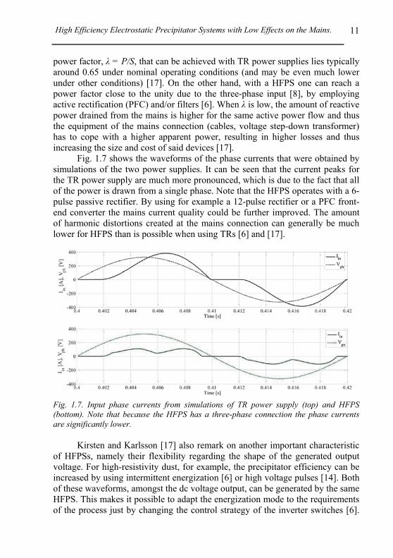
Fig. 1.7 shows the waveforms of the phase currents that were obtained by simulations of the two power supplies. It can be seen that the current peaks for the TR power supply are much more pronounced, which is due to the fact that all of the power is drawn from a single phase. Note that the HFPS operates with a 6-pulse passive rectifier. By using for example a 12-pulse rectifier or a PFC front-end converter the mains current quality could be further improved. The amount of harmonic distortions created at the mains connection can generally be much lower for HFPS than is possible when using TRs [6] and [17].
Fig. 1.7. Input phase currents from simulations of TR power supply (top) and HFPS (bottom). Note that because the HFPS has a three-phase connection the phase currents are significantly lower.
Kirsten and Karlsson [17] also remark on another important characteristic
of HFPSs, namely their flexibility regarding the shape of the generated output voltage. For high-resistivity dust, for example, the precipitator efficiency can be increased by using intermittent energization [6] or high voltage pulses [14]. Both of these waveforms, amongst the dc voltage output, can be generated by the same HFPS. This makes it possible to adapt the energization mode to the requirements of the process just by changing the control strategy of the inverter switches [6].
Chapter 1 – Principles of Electrostatic Precipitation.
12
While intermittent operation is also possible with TR power supplies by not firing the thyristors for a number of half cycles [6], pulsed operation can only be achieved with a separate high voltage pulse generator when TRs are used [17].
1.4.2 Economic Aspects
Because in an HFPS the high voltage transformer is operated at frequencies much higher than the mains frequency, it can be built much smaller. Thus, as the mains-frequency-operated transformer of a TR power supply is by far its biggest and heaviest part, an HFPS with better performance can be built with only about 15 % of the weight of a TR power supply [12]. Kirsten and Karlsson [17] quote, for example, a weight of 1000 to 2000 kg for only the transformer of a conventional power supply and compare it with the 250 kg overall weight of a complete 60 kW HFPS.
The reduced weight has significant advantages. It makes the transport of the unit much easier and facilitates its installation. This is especially important as power supplies are commonly installed on the roof of the actual ESP. The required equipment for lifting 2000 kg is obviously much more sophisticated and/or costly than that used to lift only 250 kg [17]. Moreover, for newly built plants the construction of the roof doesn’t need to be as sturdy if the weight it has to support is lower [17]. Additionally, it is possible to build the comparatively small transformer of a HFPS without the use of mineral oil that is commonly used as an insulation and cooling fluid in mains frequency high-voltage transformers. Thus, there is no leakage risk and the need for secondary equipment like expansion tanks and pipes is eliminated [6]. Even if oil is used, the amount is minor and therefore it is anyhow not necessary to build expensive leakage oil pans with an appropriate sewage system [17]. Thus, the lower size and weight of a HFPS in addition to its more or less oil-free design lead to reduced transportation and installation costs.
Note that a conventional TR high-voltage power supply consists of various parts. There are several control cabinets, usually located in a separate switchgear room (which has to be built and commonly has to be equipped with air-conditioning because of waste heat produced by the thyristors), the transformer, typically located on to the ESP roof as mentioned above, and interconnections between the two; that is, high-voltage cables and also signal cables for measurements [17]. On the other hand, a HFPS is usually a ''one-box unit'' with simply a mains and a high voltage connection. The latter serves, at the same time, as mounting for the whole unit. Thus, the HFPS (or several of them for a multiple zone ESP) can be placed on the roof and very few other components have to be installed and thus a switchgear room is not necessarily needed [17]. Therefore, the installation of an HFPS power supply is a lot easier and less time-consuming. The ''one-box''-characteristic is also beneficial for upgrading existing ESPs from TR to high-frequency power supplies [17].
The maintenance costs of a HFPS are normally lower than those of TR
High Efficiency Electrostatic Precipitator Systems with Low Effects on the Mains.
13
power supplies. Due to the modular ''one-box''-design, their low weight and small size, it is, for example, possible to just swap the whole power supply with a spare one, so the interruption time of plant operation (or duration of higher emissions) can be limited. Another advantage is that usually the whole HFPS is made by one manufacturer and thus there is a unique expert contact in case of problems [17].
As already described in Section 1.4.1, because a HFPS is connected to all three mains phases, the input currents per phase are significantly lower compared with the single-phase connected TR power supply. Due to the very high power factor that can be achieved with HFPS, the losses in the cables, switchgear and also in the grid voltage step-down transformer are further reduced. Thus, these pieces of equipment can be of smaller dimension and are consequently less expensive [6].
Additionally, the losses within the power supply itself are significantly lower for a HFPS. Kirsten and Karlsson [17] quote a ''rule of thumb'' which is that for a TR power supply one can assume losses of about 15 % of the rated power whereas for HFPS these losses amount to only 5 %. Both values are for nominal operation at full load. As a concrete example, industrial trials with several ESP installations carried out in [18] found a significantly reduced kVA input power (by about a factor of 2.9) while the precipitation performance was maintained or even increased when applying HFPS instead of conventional power supplies to the same ESP. However, the observed reduction of apparent input power does presumably already include the benefits of the higher power factor of HFPS [5].
Utilities may require customers to ensure an average power factor above a certain value, e.g. 0.9 [19]. When a conventional power supply is used, either some sort of power factor correction has to be employed to meet this requirement, leading to increased installation costs or the electricity rate may be set to a higher level by the utility. In any case, with an HFPS the operating costs for the same emission levels are potentially lower due to reduced energy consumption and the simpler maintenance when compared with conventional power supplies.
Kirsten and Karlsson [17] did an exemplary estimate of the costs associated with the installation of an entirely new ESP on a newly built plant or an upgrade situation where the power supply of an existing ESP is replaced with an HFPS. They conclude that for a new plant the HFPS is generally less expensive. For the upgrade situation where the initial costs of the conventional power supply do not have to be considered because it is already there, the break-even point is still reached within few years, which is not a long time when compared to the lifetime of the ESP equipment.
1.4.3 Comparison TR vs. HFPS Summary
The important points from the comparison between TR and HFPS power
Chapter 1 – Principles of Electrostatic Precipitation.
14
supplies are summarized in Table 1.1. It is evident from the study presented in Section 1.4.1 and 1.4.2 that the application of HFPS as a high voltage source for electrostatic precipitators has significant advantages over the conventional mains-frequency energization. The high switching frequency used in HFPS allows for comparatively small overall size and low weight which both make the installation of the equipment simpler. More importantly, the high switching frequency leads also to a very smooth dc output voltage with negligible ripple and thus higher power in-feed to the precipitator which generally results in higher collection efficiency. Another effect is the much faster control response that can be achieved with HFPS. This leads to faster sparkover handling and hence also increases the efficiency and reduces the stress on the ESP electrodes. Table 1.1. Summary of the comparison of conventional thyristor-based mains-frequency power supplies (TR) and modern high-frequency power supplies (HFPS).
Features TR HFPS
Output characteristics
Large voltage ripple dominated by mains frequency
Negligible voltage ripple and thus higher VESP,avg and higher
corona current
Output power and efficiency
Lower VESP,avg and less corona current, hence less particle
collection
Higher output power and thus generally higher collection
efficiency
Control and sparkovers
Slower control (10 ms), downtime due to sparkover up
to 100 ms
Very fast (20 µs), downtime due to sparkover below 10 ms
Mains impact
Single-phase connection → high current. Power factor normally < 0.7. Harmonic
distortion form factor > 1.3 and increasing for partial load
Three-phase connection, relatively high power factor, form factor ≈ 1.2 and load
independent
Flexibility Intermittent energization
possible, no µs-pulses
Variety of output waveforms from same device by varying
switching scheme, 50 µs pulse possible
Installation
Large, separate components (transformer, control cabinets,
HV cables), transformer weighs 1000 kg to 2000 kg and
contains oil
Small “one-box” – unit, whole unit weighs around 250 kg, oil-free transformer possible
Power conversion efficiency
About 15% losses in the device itself, higher losses in mains-
side equipment due to low power factor
About 5% losses in the device itself, only small losses in
mains-side equipment.
As a HFPS has a three-phase mains connection, it is a symmetric load. A
relatively high power factor over the whole operation range can be achieved, leading to reduced losses in the mains-side equipment. The power conversion
High Efficiency Electrostatic Precipitator Systems with Low Effects on the Mains.
15
efficiency of the power supply itself is also significantly higher and therefore the overall energy consumption can be reduced by using HFPS instead of TR power supplies.
In Section 1.5 the distortions caused by a group of high-frequency power supplies feeding an Electrostatic Precipitator (ESP) are investigated, and means for improving the line power quality of the system are suggested.
Fig. 1.8. Typical ESP installation scheme of a system with 24 power supplies.
1.5 HFPS and the Line Power Quality
Industrial ESPs are normally divided into several sections or zones in order to increase their collection efficiency [20]. Each of these sections has its own Power Supply (PS), which is controlled individually and has a typical output power range of 10 kW to 120 kW and a DC output voltage range of 30 kV to 100 kV [4]. These supplies can have different converter topologies or configurations, depending on their location within the ESP [15]. In outlet zones, for example, pulsed voltages are used more and more frequently, as they increase the particle collection efficiency. A typical ESP electrical installation is depicted in Fig. 1.8, where due to the large number of ESP zones and the high power processed, a dedicated substation with two or more voltage step-down transformers are commonly used.
Chapter 1 – Principles of Electrostatic Precipitation.
16
In the Section 1.4.1 a brief description of the influence of continuous energization on the grid line power quality for a single ESP power supply based on TR and HFPS technologies, was given. Despite the superior performance of the HFPS system, this concept employing a three-phase diode-based rectifier as front-end still injects significant current harmonics into the power system installation. This could cause a distortion of the mains voltage at the point of common coupling. Furthermore, higher line current distortion and drastically unbalanced loading of the mains phases could occur, especially in pulsed operation. Accordingly, the concept employed today bears the risk of causing severe problems such as malfunction of other equipment fed by the same mains, audible noise, increased losses of transformers, generators and power lines, electric resonances in the mains, overloading of nearby capacitors and mechanical oscillations in generators [22] and [23].
The line power problem in ESP applications can become worse for relatively large industrial ESPs, where groups of up to 30 power supplies with pulsed operation are fed by the same mains as the pulses in different supplies can occur at the same instant. On the other hand, as shown in [23], if the pulses in each power supply are scheduled in an optimal way it is possible to reduce the undesirable effects in this type of operation, so that the power consumption becomes more continuous over time. This pulse optimization strategy is presented in Chapter 3.
To illustrate the effects of the pulsed energization on the power quality of the mains, a system of five power supplies fed by the same mains was simulated. The power supplies of the ESP considered in this example are similar to the HFPS depicted in Fig. 1.5. Herein, the following operation conditions are investigated:
• The “Critical Case”: The power supplies operate in pulsed mode with a pulse width of 3 ms and a period of 12 ms. The pulses of all power supplies are arranged to occur at the same time, aggravating the problems with mains quality. Fig. 1.9 shows the simulation results;
• The “Optimized Case”: The power supplies operate in pulsed mode, with the same configuration as for the “Critical Case”. In this analysis, the pulses are equally distributed in a pulse period (TP) in order to obtain more continuous power consumption (optimization by scheduling of the pulses). Fig. 1.10 presents the simulation results;
• The “Continuous Case”: The power supplies operate in continuous mode. This system was configured to require a similar amount of power as the “Optimized Case”. Fig. 1.11 shows the obtained simulation results. Note that the mains behaviour observed in this analysis is the target of the optimization by scheduling of the pulses.
By analysing Fig. 1.9, one can observe that the line currents are unbalanced and highly distorted. The power balance on the mains is critical as high line current peaks appear when the pulses are released, and almost no
High Efficiency Electrostatic Precipitator Systems with Low Effects on the Mains.
17
current is required with no pulse. These effects are due to the voltage variation of the load, which causes a low frequency disturbance in the bus-bar capacitor voltage VLink. When the capacitor voltage drops, the diode current conduction angle is increased. On the other hand, when this voltage rises the diode current conduction is blocked.
Fig. 1.9. Simulation results when the pulses of all power supplies are arranged to occur at the same time: (a) ESP applied voltage for each power supply; (b) line currents; and (c) instantaneous demanded power.
As can be observed in Fig. 1.10, the “Optimized Case” has similar behaviour to a group of power supplies operating in continuous mode (cf. Fig. 1.11). The line currents are balanced with a harmonic distortion which is significantly improved when compared to the “Critical Case”. Moreover, it can be observed that the lower THD of the line currents generates less oscillation to the demanded power (cf. Fig. 1.10(c)). In terms of power quality, the ideal scenario is considered to be when the line currents absorbed by the power supplies and voltages of the mains are in phase, with sinusoidal waveforms. In this case, the ESP system would operate with a unity power factor, draining
Chapter 1 – Principles of Electrostatic Precipitation.
18
constant power from the mains over time. Note that in this analysis the voltages of the mains are purely sinusoidal and for this reason the oscillations observed on the instantaneous power waveform are due to the line current harmonics.
1.5.1 Harmonic Effects on Mains Installation Components
Pulsed operation influences the mains power quality considerably as it can result in high line current distortion and unbalanced mains phase loading (cf. Fig 9). In general, distorted currents on each segment of the electrical installation interact with the grid components, causing voltage distortions.
Fig. 1.10. Simulation results when the pulses of all power supplies are equally distributed over a pulse period: (a) ESP voltage applied for each power supply; (b) line currents; and (c) instantaneous demanded power.
With reference to [24]-[30], the energy loss impact associated with
harmonics and reactive power circulating in the ESP electrical system main
High Efficiency Electrostatic Precipitator Systems with Low Effects on the Mains.
19
components is presented in the following.
Fig. 1.11. Simulation results for conventional energization: (a) ESP voltage applied for each power supply; (b) line currents; and (c) instantaneous demanded power.
• Transformer: Distribution transformer losses PT are generally classified into no load or core losses PNL and load losses PLL [24]-[30],
T NL LLP P P . (1.2)
Core or no-load loss is mainly related to the voltage excitation of the core. Slightly distorted transformer voltage would be expected as harmonic currents pass through the leakage impedance [25]. The magnetizing current harmonics are very small when compared to the load current, thus their effects on the losses are negligible.
The load loss is divided into I2R loss and stray loss (1.3). In a first step approximation the I2R loss is caused by the square of the load rms current and the
Chapter 1 – Principles of Electrostatic Precipitation.
20
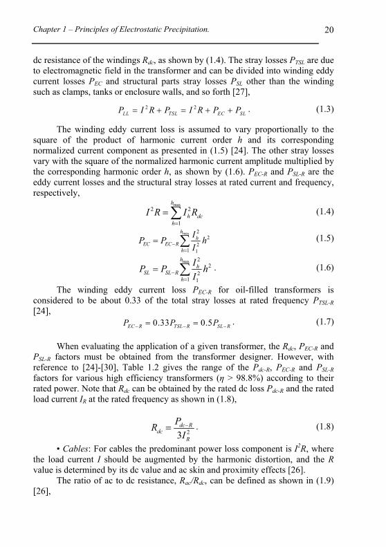
dc resistance of the windings Rdc, as shown by (1.4). The stray losses PTSL are due to electromagnetic field in the transformer and can be divided into winding eddy current losses PEC and structural parts stray losses PSL other than the winding such as clamps, tanks or enclosure walls, and so forth [27],
2 2
LL TSL EC SLP I R P I R P P . (1.3)
The winding eddy current loss is assumed to vary proportionally to the square of the product of harmonic current order h and its corresponding normalized current component as presented in (1.5) [24]. The other stray losses vary with the square of the normalized harmonic current amplitude multiplied by the corresponding harmonic order h, as shown by (1.6). PEC-R and PSL-R are the eddy current losses and the structural stray losses at rated current and frequency, respectively,
max2 2
1
h
h dch
I R I R
(1.4)
max 22
21 1
hh
EC EC Rh
IP P h
I
(1.5)
max 22
21 1
hh
SL SL Rh
IP P h
I
. (1.6)
The winding eddy current loss PEC-R for oil-filled transformers is considered to be about 0.33 of the total stray losses at rated frequency PTSL-R [24],
0.33 0.5EC R TSL R SL RP P P . (1.7)
When evaluating the application of a given transformer, the Rdc, PEC-R and
PSL-R factors must be obtained from the transformer designer. However, with reference to [24]-[30], Table 1.2 gives the range of the Pdc-R, PEC-R and PSL-R factors for various high efficiency transformers (η > 98.8%) according to their rated power. Note that Rdc can be obtained by the rated dc loss Pdc-R and the rated load current IR at the rated frequency as shown in (1.8),
23dc R
dcR
PR
I . (1.8)
• Cables: For cables the predominant power loss component is I2R, where the load current I should be augmented by the harmonic distortion, and the R value is determined by its dc value and ac skin and proximity effects [26].
The ratio of ac to dc resistance, Rac/Rdc, can be defined as shown in (1.9) [26],
High Efficiency Electrostatic Precipitator Systems with Low Effects on the Mains.
21
1acCS CP
dc
Rk k
R , (1.9)
where kCS is the resistance increase due to skin effect, and kCP is the increase in resistance due to the proximity effect. According to [27] and [28] the component of resistance due to skin effect can be expressed as given in (1.10) and (1.11),
0.027678dc
f ux
R , (1.10)
3 5 4 3 2
3 5 4 3 2
6 5 4 3 2
10 1.04 8.24 3.24 1.447 0.2764 0.0166 2
10 0.2 6.62 83.35 500 1061.9 769.63 2 10
10 0.105 10.83 432.5 8200 297190 512944 10 100
CS
x x x x x for x
k x x x x x x for x
x x x x x for x
, (1.11)
where f is the frequency in Hz, u is the magnetic permeability of the conductor, and Rdc is the dc resistance in Ω/1000 ft at operating temperature.
The component of resistance due to proximity effect can be expressed as (1.12), where σ represents the ratio of the conductor diameter and the axial spacing between conductors [28],
2 21.18
0.3120.27CP CS
CS
k k xk x
. (1.12)
• Capacitor Banks: The application of capacitors in a system loaded with harmonics must be done with care not only because of possible resonance problems, but also because the capacitors themselves have definite rating limitations associated with their application [28].
Following [28], there are three specific ratings of concern when capacitors are applied in a non-sinusoidal waveform environment: capacitor rated reactive power capability (cf. (1.13)), rated terminal rms voltage Vrms (cf. (1.14)), and rated rms current Irms (cf. (1.15)),
max 2
1
1.35h
h
h
IkVAr pu
h
, (1.13)
max
2
1
1.1h
rms hh
V pu V
, (1.14)
max
2
1
1.8h
rms hh
I pu I
, (1.15)
where kVAr(pu) is the total reactive power in pu, Ih is the capacitor harmonic current in pu of the rated capacitor current, h is the harmonic order, and Vh is the
Chapter 1 – Principles of Electrostatic Precipitation.
22
capacitor rms harmonic voltage in pu.
• Other Electrical Equipment: For motors and relays, the primary loss mechanism is the harmonic voltage that is present at the terminals of the equipment. For power system components such as standby generators or series reactors, the harmonic current is the predominant loss factor, [26] and [30].
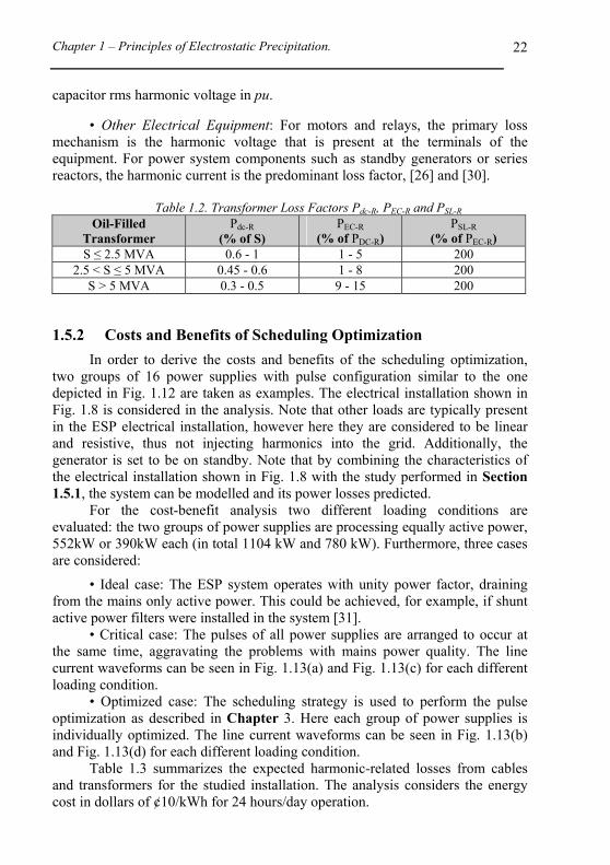
Table 1.2. Transformer Loss Factors Pdc-R, PEC-R and PSL-R
1.5.2 Costs and Benefits of Scheduling Optimization
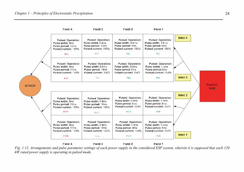
In order to derive the costs and benefits of the scheduling optimization, two groups of 16 power supplies with pulse configuration similar to the one depicted in Fig. 1.12 are taken as examples. The electrical installation shown in Fig. 1.8 is considered in the analysis. Note that other loads are typically present in the ESP electrical installation, however here they are considered to be linear and resistive, thus not injecting harmonics into the grid. Additionally, the generator is set to be on standby. Note that by combining the characteristics of the electrical installation shown in Fig. 1.8 with the study performed in Section 1.5.1, the system can be modelled and its power losses predicted.
For the cost-benefit analysis two different loading conditions are evaluated: the two groups of power supplies are processing equally active power, 552kW or 390kW each (in total 1104 kW and 780 kW). Furthermore, three cases are considered:
• Ideal case: The ESP system operates with unity power factor, draining from the mains only active power. This could be achieved, for example, if shunt active power filters were installed in the system [31].
• Critical case: The pulses of all power supplies are arranged to occur at the same time, aggravating the problems with mains power quality. The line current waveforms can be seen in Fig. 1.13(a) and Fig. 1.13(c) for each different loading condition.
• Optimized case: The scheduling strategy is used to perform the pulse optimization as described in Chapter 3. Here each group of power supplies is individually optimized. The line current waveforms can be seen in Fig. 1.13(b) and Fig. 1.13(d) for each different loading condition.
Table 1.3 summarizes the expected harmonic-related losses from cables and transformers for the studied installation. The analysis considers the energy cost in dollars of ¢10/kWh for 24 hours/day operation.
High Efficiency Electrostatic Precipitator Systems with Low Effects on the Mains.
23
The results compiled in Table 1.3 show that non-scheduled ESP systems are expensive and inefficient, as up to 33% higher apparent power is demanded from the mains. The uncontrolled pulsed operation, in general, reduces the electrical system’s distribution capacity and its reliability by increasing current flow, causing mains phases loading unbalances, and yielding to higher voltage drops when compared to the optimized or ideal cases. On the other hand, the proposed pulse optimization enhances the electrical system capacity and also reduces power losses (-4.4 kW for 1104kW loading). In addition, the scheduling method can considerably reduce electricity bills as many utility companies charge additional fees if the power factor of the industrial installation is below a certain level.
1.6 Pulsed ESP Systems with Improved Line Power Quality
In this section, aiming for pulsed ESP systems with high power factor operation, alternative replacements for the three-phase diode bridge rectifier commonly used in HFPS (cf. Fig. 1.5) are discussed and evaluated for the ESP installation depicted in Fig. 1.8, operating with pulse configuration shown in Fig. 1.12. Therein, the high voltage pulses applied to the ESP system are optimized with the pulse scheduling strategy presented in Section 1.5 (cf. Chapter 3).
1.6.1 ESP System Employing Multi-Pulse Solution
In the typical ESP electrical installation depicted in Fig. 1.8, three-phase transformers providing phase shift between primary and secondary windings in multiples of 30 degrees could be employed to feed the ESP’s power supplies in a three-wire system. Hence, a multi-pulse system can be built by selecting suitable voltage step-down transformers, where the simplicity and reliability of ESP power supplies are preserved.
Unfortunately, the performance of passive multi-pulse systems strongly depends on the load balance between the secondary sides of the transformers, which could be difficult to achieve in a pulsed ESP system, as the dust particle load in different bus sections can vary considerably during operation. This issue can be addressed by ESP power supplies featuring modularization by parallel connection of converters [64] (cf. Fig. 1.14) as each unit could operate as a 12-pulse passive rectifier as shown in Fig. 1.15(a). This system can preserve the multi-pulse characteristics of the line currents, even when some of the power supplies suffer from sparkovers as presented in the simulation results depicted in Fig. 1.15(b). Therein, the sparkover takes place solely in the bus section of one power supply, while the other power supply unit continues operating. After the sparkover is extinguished, both power supplies are considered to be operating at full power.
Chapter 1 – Principles of Electrostatic Precipitation.
24
Fig. 1.12. Arrangements and pulse parameter settings of each power supply in the considered ESP system, wherein it is supposed that each 120 kW rated power supply is operating in pulsed mode.
High Efficiency Electrostatic Precipitator Systems with Low Effects on the Mains.
25
Fig. 1.13. ESP system line currents: (a) Critical Case and (b) Optimized Case for 552kW operation; (c) Critical Case and (d) Optimized Case for 390kW operation. Note that the current waveforms shown here are due to the operation of the 16 power supplies system shown in Fig. 1.12.
High Efficiency Electrostatic Precipitator Systems with Low Effects on the Mains.
26
Table 1.3. Summary of harmonic related losses and costs per year
Active Power of the ESP System
≈ 1104 kW (p.u. Ibase=800 A) ≈ 780 kW (p.u. Ibase=565 A)
Transformer T1 Loss (W) 33316 33476 33635 32721 32887 32927
Transformer T2 & T3 Losses (W)
27418 27774 28153 26587 26932 27144
Transformer T4 & T5 Losses (W)
5608 7987 10467 4672 6760 8962
Total installation power loss (kW)
77.11 81.20 85.62 73.92 77.58 81.21
1 year energy loss cost (10¢/kWh)
67598 71182 75058 64796 68011 71191
Cost Harmonic Related Losses 0 3584 7460 0 3215 6395
Chapter 1 – Principles of Electrostatic Precipitation.
27
Fig. 1.14. ESP power supplies based on series-parallel resonant converters featuring modularization by parallel connection of converters.
Considering that the electrical installation only have one voltage step-
down transformer unit delivering power to the ESP system, an auxiliary low voltage level (LV) autotransformer with differential connection, processing only about 21% of the load power, can be used to build a 12-pulse rectifier system. In this case, ESP power supplies with modularization by paralleling (cf. Fig. 1.14) could also be used to improve the load sharing between the secondary windings of the autotransformer. A block diagram of the proposed system is shown in Fig. 1.16.
Fig. 1.24(a) presents the simulation results of the analysed system (cf. Fig. 1.16 and Fig. 1.12), employing power supplies as the ones shown in Fig. 1.5. As can be observed, a low harmonic content of the input current can be achieved (THD=13.1% up to 25th harmonic). As this solution employs a low frequency multi-pulse transformer processing a high amount of power, the system becomes relatively heavy, expensive and bulky. However, the electric installation and system operation are reliable and simple.
It is important to point out that for multi-pulse systems, the pulse scheduling strategy displays better performance if each secondary winding of the transformer is considered as an isolated ESP system. Hence, each isolated ESP system should be optimized separately. For the system depicted in Fig. 1.12, for example, the power supplies in the rows Inlet 1 and 2 can be fed by one secondary of the transformer, whilst the power supplies located in the rows Inlet 3 and 4 can be energized by the other secondary winding.
High Efficiency Electrostatic Precipitator Systems with Low Effects on the Mains.
28
(a)
(b)
Fig. 1.15. 12-pulse ESP system: (a) ESP system arrangements using typical electrical installation and modern ESP power supplies; and (b) mains’ phase current and voltage for system under sparkovers.
Fig. 1.16. 12-pulse ESP system employing autotransformer.
Chapter 1 – Principles of Electrostatic Precipitation.
29
1.6.2 ESP System Employing Active Rectifiers
Due to the relatively low losses in the semiconductors and low rated power of the inductive components, the three-phase 3-level 6-switch VIENNA rectifier, depicted in Fig. 1.17, constitutes a very good alternative for replacing the three-phase diode bridge rectifiers of the ESP power supply illustrated in Fig. 1.5. This topology features high power efficiency operation and can obtain very low harmonic content of the input current. By controlling the bus bar capacitor voltage, a maximum utilization of the back-end converter for a wide input voltage region can be achieved. With the possibility of operating at a high voltage, the losses and volumes of the back-end converter components can be reduced. In addition, this fully active solution allows a two-phase operation [69].
In order to evaluate the performance of the ESP power supply employing a VIENNA rectifier, simulations were performed for a 120 kW system operating with typical ESP energization. The results for continuous operation with sparkovers and for pulsed operation are presented in Fig. 1.18 and Fig. 1.19, respectively. By analysing these results, it can be noticed that the proposed ESP power supply based on the VIENNA rectifier has outstanding performance faced with typical ESP energizations. This shows that the system depicted in Fig. 1.17 is suitable for ESP power supply applications. For more details about an ESP HFPS employing a VIENNA rectifier as front-end, the reader is referred to Appendix A.
The simulation results for the ESP system depicted in Fig. 1.12, fully operating with active front-end rectifiers, are presented in Fig. 1.24(b). A system with balanced mains phases loading and also very low harmonic content of the input currents (4.02%) can be observed.
1.6.3 ESP Systems Employing Active and Passive Rectifier
HFPS power supplies based on active rectifiers can be strategically configured in the ESP system to compensate the reactive power generated by other power supplies fed by the same mains (cf. [70] and [71]). To show this concept two power supplies operating according to the arrangement depicted in Fig. 1.20(a) are simulated. Therein, an ESP bus section uses a power supply based on a three-phase bidirectional voltage source rectifier and another bus section employs a three-phase diode bridge rectifier. By proper shaping the line current delivered for both ESP power supplies, the active solution can effectively compensate all the current harmonics drained from the mains (cf. Fig. 1.20(b)). Note that when the bidirectional power supply is not pulsing it is operating as an active filter.
High Efficiency Electrostatic Precipitator Systems with Low Effects on the Mains.
30
Fig. 1.17. ESP power supply based on VIENNA rectifier.
Chapter 1 – Principles of Electrostatic Precipitation.
31
Fig. 1.18. Simulation results for continuous operation under flashover rate of 100 Hz: (a) power delivered to the ESP plates; (b) rectifier stage output voltages; and (c) mains phase currents and voltage.
High Efficiency Electrostatic Precipitator Systems with Low Effects on the Mains.
32
Fig. 1.19. Simulation results for pulsed operation with pulse period of 10 ms and pulse width of 2.5 ms: (a) power delivered to the ESP plates; (b) rectifier stage output voltages; and (c) mains phase currents and voltage.
Chapter 1 – Principles of Electrostatic Precipitation.
33
For the system depicted in Fig. 1.12 employing this solution and the pulse scheduling strategy, 25% of the converters are considered to utilize bidirectional voltage source rectifiers. To decrease the impact of an eventual active rectifier failure on the ESP collection efficiency, each row of the system contains just one active structure positioned in the middle fields where the power supplies are set to pulse only for a short time. In this case, the active rectifiers work almost 92% of the time only as active filters. Fig. 1.25(a) shows the simulation results of this ESP system. Therein, line currents with sinusoidal shape (2.6% of current THD up to the 25th harmonic) can be obtained. One drawback of this solution is that it requires two different ESP power supply technologies. Even though only 25% of the power supplies employ the active rectifier solution, the apparent power handled by these structures is relatively high (57% of the load power) due to the high reactive power processed. Clearly, the system reliability is higher than for the fully active solution presented in Section 1.6.2.
1.6.4 ESP System Employing Shunt Active Filter Solution
To further improve the line power quality of the system depicted in Fig. 1.12, a shunt active filter (AF) can be employed as presented in Fig. 1.21. The simulation results for this solution are depicted in Fig. 1.25(b). The active filter processes a high amount of reactive power (68% of the load power) to ensure a sinusoidal shape of the line currents (THD = 2.1% up to the 25th harmonic). Alternatively, the active filter could be set to only compensate current harmonics to achieve a sinusoidal shape of the line current, without then correcting the displacement between the mains phase voltages and the line currents. In this way, the amount of reactive power processed would be considerably reduced, increasing the system power efficiency. The reliability of the ESP power supplies based on passive rectifiers is preserved as in case of a failure of the active filter the system can remain in operation.
1.6.5 ESP System Employing Shunt Active Filter and Multi-Pulse Solution
An ESP system with high line power quality can be derived combining a shunt active filter and a multi-pulse transformer. To obtain high power efficiency, an autotransformer with differential connection, processing only about 21% of the load power, is used to build the 12-pulse rectifier. In addition, a shunt active filter is installed on the primary side of the autotransformer (cf. Fig. 1.22).
The simulation result for the proposed solution is presented in Fig. 1.26(a). As can be seen, a very low harmonic content of the input current can be achieved (THD = 1.48%). Due to the fact that this solution employs a multi-pulse transformer processing high apparent power, the system becomes heavy, expensive and bulky. To allow a system with resistive mains behaviour, the
High Efficiency Electrostatic Precipitator Systems with Low Effects on the Mains.
34
active filter needs to process the amount of reactive power of only about 19.2% of the load power. This considerably increases the power efficiency of the system.
(a)
(b)
Fig. 1.20. ESP system employing a power supply based on bidirectional voltage source rectifier and other power supply based on passive rectifier: (a) circuit diagram of the ESP system; and (b) main system waveforms.
4 ms/div.
Chapter 1 – Principles of Electrostatic Precipitation.
35
Fig. 1.21. ESP system employing a shunt active filter.
AutotransformerMains
16 ESP Power Suplies 16 ESP Bus Sections
Shunt Active Filter
Fig. 1.22. ESP system employing a 12 pulse transformer and shunt active filter.
1.6.6 Dc Distribution System
A dc distribution system could be designed to deliver power to the ESP system depicted in Fig. 1.12. Any rectifier topology suitable for an ESP front-end converter could be used. In this study, as illustrated in Fig. 1.23, a hybrid system comprising a bidirectional voltage source rectifier and a three-phase diode bridge rectifier + dc-dc boost converter was selected in order to increase the system reliability. Thus, in case of failure of one of the rectifier units, the other working structure can continue delivering full power to the ESP system [70] and [71]. The total cost of the structure becomes high as each active rectifier is designed to cope with full load power. In order to increase the system power efficiency, the bidirectional structure is set to process active power of only about 20% of the load power, P0, whilst the active boost delivers the other 80% of P0. The simulation results for the considered dc distribution system are shown in Fig. 1.26(b). As can be observed, the system achieves relatively low harmonic content
16 ESP Power Supplies 16 ESP Bus Sections
Shunt Active Filter
Mains Autotransformer
Shunt Active Filter
16 ESP Power Supplies 16 ESP Bus Sections Mains
High Efficiency Electrostatic Precipitator Systems with Low Effects on the Mains.
36
of the input currents (THD= 7%). This system presents the lowest reliability among the analysed concepts. However, several parallel connected converters could be employed to increase the system reliability and/or operating features.
Fig. 1.23. Dc distribution system based on a hybrid rectifier delivering power to 16 back-end converters.
Chapter 1 – Principles of Electrostatic Precipitation.
37
(a) (b)
Fig. 1.24. Simulation results of the alternative solutions of electrostatic precipitator systems: (a) 12 pulse rectifier system + scheduling strategy; (b) 100% active rectifier+ scheduling strategy.
Mai Mai
High Efficiency Electrostatic Precipitator Systems with Low Effects on the Mains.
38
(a) (b)
Fig. 1.25. Simulation results of the alternative solutions of electrostatic precipitator systems: (a) 25% active and 75% passive rectifier + scheduling strategy; (b) active filter system + scheduling strategy.
Mai Mai
Mains Mains
Chapter 1 – Principles of Electrostatic Precipitation.
39
(c) (d)
Fig. 1.26. Simulation results of the alternative solutions of electrostatic precipitator systems: (a) 12 pulse rectifier system + active filter + scheduling strategy; and (b) DC distribution system+ scheduling strategy.
Mai Mai
High Efficiency Electrostatic Precipitator Systems with Low Effects on the Mains.
40
1.7 Motivations, Objectives and Contributions of the Work
From the analysis performed in Section 1.4, it becomes evident that the application of HFPSs as high voltage sources for electrostatic precipitators has significant advantages over the conventional mains-frequency energization. For new ESP plants the application of high-frequency power supplies seems natural. In many cases it can even make sense to consider an upgrade of already existing ESPs because the return on investment period is rather short due the higher efficiency that can be achieved with HFPSs. Altogether it can be said that the share of HFPS powered ESPs will most likely grow further in the future. Due to the overwhelming list of advantages of HFPSs, it can be assumed that they will virtually eliminate the utilization of TR power supplies in ESP applications over the years.
In Section 1.5 and Section 1.6 it was shown that further improvements related to the line power quality in ESP systems based on pulsed HFPS can be achieved by proper scheduling of pulses and/or by incorporating power electronic circuits with power factor control capability such as active rectifiers or shunt active power filters. Therefore, the research into high-frequency power supplies and their optimization is of high importance in order to improve and ensure highly efficient operation of ESPs.
The aim of this thesis is to suggest innovative ways for operation of ESP systems and also to propose suitable power electronic solutions for this application in order to improve the system efficiency and reduce the impact of the ESP operation on the line power quality.
The contributions of this thesis to the power electronic field are listed below:
• The Design of High-Power High-Voltage DC-DC Converters for Electrostatic Precipitators:
Because of their ability to integrate the transformer parasitic elements into the circuit operation, resonant topologies are identified as suitable solutions for an ESP power supply. Different resonant topologies, operating below and/or above resonance, employing conventional variable frequency (VF) control, conventional phase-shift (PS) control, and/or variable frequency phase-shift control (DC) are studied in Chapter 2. The series-parallel resonant converter, referred here to as LCC converter, operating above resonance with DC control is identified as a feasible choice for an ESP power supply, because of its balance of low semiconductor losses, moderate resonant current peak values, ability to withstand short-circuits and the narrow switching frequency variation in relation to the handled power. A prototype of a 60 kW LCC power supply is designed by
Chapter 1 – Principles of Electrostatic Precipitation.
41
optimizing the LCC resonant converter using a modified first-harmonic based mathematical model and a built semi-automated design procedure for the resonant tank and the high-voltage transformer.
Part of this work has been published at the IPEC 2010 conference (cf. [tbs17]) and further published in the IEEE Transactions on Industrial Electronics (cf. [tbs20]). • The Study of Concepts for Improving the Line Power Quality of Electrostatic Precipitator Systems:
In Chapter 3, a strategy to solve the inherent problems caused by pulsed operation is proposed, where the main idea is to arrange the pulses of the individual power supplies in an optimal sequence, so that the group of pulsed power supplies has similar line behaviour to that of an equivalent single power supply operating in continuous mode. The proposed system control is experimentally verified with two ESP power supplies, with each unit having a power capability of 120 kW. The results showed the advantages of the pulses scheduling concept namely, a reduction of both reactive power consumption and line current peaks; better current THD; better power balance among mains phases; and better utilization of mains components.
In Section 1.6 different solutions for improving the line power quality of pulsed ESP power supplies have been proposed. A simple way to improve the line power quality in ESP applications by using both the characteristics of the electrical installation and the typical ESP high power supply is identified and further analysed in Chapter 4. Therein, a multi-pulse system can be built by selecting a combination of suitable voltage step-down transformers, preserving the simplicity and reliability of the typical ESP HFPS which employs three-phase diode bridge rectifiers. In addition, processing only about 10% of the total system apparent power, shunt active filters (AFs) can be placed on the low voltage side of the transformer for high order harmonic-current-mitigation (>7th harmonic). In case of unbalance in the transformer loading, the AFs can also act to adjust the 5th and 7th current harmonics, which are then effectively eliminated by the multi-pulse system.
For the proposed pulse scheduling concept a patent application has been filled in 2010 (cf. [tbs1]). It has also been published in the ECCE Asia conference [tbs16]. The comparison of solutions for the group of pulsed ESP power supplied fed by the same grid has been published at the IECON 2010 in [tbs14]. Finally, a patent application for the proposed idea of operating ESP systems using multi-pulse transformer and active filters has been filed in 2010 (cf. [tbs2]). It has also been published at the IECON 2010 [tbs15].
High Efficiency Electrostatic Precipitator Systems with Low Effects on the Mains.
42
• The Design of High-Power AC-DC Converters with Low Effects on the Mains for Electrostatic Precipitator Applications:
In Chapter 5, in order to fulfil mains power quality requirements, i.e. IEC 61000-3-2/61000-3-4 guidelines, suitable front-end converters for ESP HFPSs are investigated as replacements for three-phase diode bridge rectifiers. A comparison of the studied systems, rated to 60 kW and fully designed employing commercial components, is performed, where the power efficiency of the ESP system, power density, and current THD, among other characteristics, are used for the assessment. The analysis is extended to a variable power semiconductor chip area to allow a fair comparison between the studied systems. The VIENNA 6-switch rectifier, further evaluated in Appendix A, is identified as a feasible choice for an ESP power supply, because of its low semiconductor losses and low rated power of the inductive components.
Part of this study has been published at the ECCE Asia 2011 (cf. [tbs13]). Additionally, an interesting hybrid rectifier system has been identified and a paper about it has been published at the IECON 2011 (cf. [tbs11]). New control schemes appropriate to improve the power sharing rating of the proposed unidirectional hybrid rectifier and able to handle a phase loss without changing the controller structure, have been proposed and a patent application was filled (cf. [tbs4]). A paper presenting the analysis and implementation of three-phase two- and three-level unidirectional hybrid rectifiers has been published in the IEEE Transactions on Industrial Electronics (cf. [tbs21]). • High Efficiency Multi-Level Active Filters with Enhanced Bridge-Leg Loss Distribution:
New 3-level voltage source converters (VSCs) featuring improved power semiconductor loss distribution, named as 3-level hybrid Neutral-Point-Clamped (NPC) converters, have been proposed in [tbs10]. These VSCs can achieve not only higher efficiency than typical 3-level structures (NPC or T-type VSCs), but, as the A-NPC converter, the proposed concept can also suppress their drawback of asymmetrical semiconductor loss distribution. A patent application of the presented 3-level VSCs has been filed in 2011 (cf. [tbs5]).
Several voltage source converters suitable for three-phase active filter applications have been investigated in [tbs12]. As replacements for the widely used 2-level VSC, and 3-level VSC structures such as the conventional NPC VSC, the Active NPC (A-NPC), and different T-type VSC solutions are investigated. In order to address the loss distribution issue of the 3-level topologies, while keeping the efficiency of the system high, a space vector modulation scheme incorporating a special clamping of the converter phase-legs is proposed. It is shown that conventional 3-level active filters can have their
Chapter 1 – Principles of Electrostatic Precipitation.
43
losses well distributed over the power semiconductor dies, leading to only a small difference in their operating temperatures. Additionally, a semiconductor area based comparison is used to further evaluate the studied active filter systems.
1.8 Publication Overview
In the course of this dissertation the following patents, and conference and journal papers have been published: Patent Applications [tbs1] T. Soeiro, J. Biela, J. Linner, and P. Ranstad, “Method for the operation of
electrostatic precipitators”. App. nr. PCT/EP2011/060129. [tbs2] J. W. Kolar, T. Soeiro, J. Linner, and P. Ranstad, “Method to minimize input
current harmonics such as ESP power systems”. App. nr. PCT/EP2011/059131. [tbs3] T. Soeiro, J. W. Kolar, J. Linner, and P. Ranstad, “Method and device for
determining a control scheme for an active power filter”. App. nr. US 13/117.972. [tbs4] T. Soeiro, J. W. Kolar, J. Linner, and P. Ranstad, “Hybrid rectifier and method for
operating such hybrid rectifier”. App. nr. EP 11187884.9. [tbs5] T. Soeiro, J. W. Kolar, J. Linner, and P. Ranstad, “Voltage source converter (VSC)
with neutral-point-clamped (NPC) topology and method for operating such voltage source converter”. App. nr. EP 11187801.3.
[tbs6] T. Soeiro, J. W. Kolar, J. Linner, and P. Ranstad, “Method for determination of a control scheme for a NPC VSC”. App. nr. EP 2528222.
Conference Papers [tbs7] F. Vancu, T. Soeiro, J. Mühlethaler, D. Aggeler, and J.W. Kolar, “Comparative
evaluation of bidirectional buck-type PFC converter systems for interfacing residential dc distribution systems to the smart grid,” in Proc. of the 38th Annual Conf. of the IEEE Ind. Electr. Society (IECON), Montreal, CA, 2012.
[tbs8] T. Soeiro, T. Friedli, and J.W. Kolar, “Swiss rectifier - A novel three-phase buck-type PFC topology for electric vehicle battery charging,” in Proc. of the 26th Ann. IEEE Appl. Power Electron. Conf. and Exp. (APEC), Orlando, USA, Feb. 2012.
[tbs9] T. Soeiro, T. Friedli, and J.W. Kolar, “Three-phase high power factor mains interface concepts for electrical vehicle battery charging systems,” in Proc. of the 26th Ann. IEEE Appl. Power Electron. Conf. and Exp. (APEC), Orlando, USA, Feb. 2012.
[tbs10] T. Soeiro, and J.W. Kolar, “Novel 3-level hybrid neutral-point-clamped converter,” in Proc. of the 37th Annual Conf. of the IEEE Ind. Electr. Society (IECON), Melbourne, AUS, Nov. 2011.
[tbs11] T. Soeiro, T. Friedli, M. Hartmann, and J.W. Kolar, “New unidirectional hybrid delta-switch rectifier,” in Proc. of the 37th Annual Conf. of the IEEE Ind. Electr. Society (IECON), Melbourne, AUS, Nov. 2011.
[tbs12] T. Soeiro, M. Schweizer, and J.W. Kolar, “Comparison of 2-level and 3-level
High Efficiency Electrostatic Precipitator Systems with Low Effects on the Mains.
44
active filters with enhanced bridge-leg loss distribution,” in Proc. of the IEEE Intern. Power Electr. Conf. (ECCE Asia), Jeju, Korea, May 2011.
[tbs13] T. Soeiro, T. Friedli, and J.W. Kolar, “Comparison of electrostatic precipitator power supplies with low effects on the mains”, in Proc. of the IEEE Intern. Power Electr. Conf. (ECCE Asia), Jeju, Korea, May 2011.
[tbs14] T. Soeiro, J. Biela, J. Linner, P. Ranstad, and J.W. Kolar, “Comparison of concepts for improving the line power quality of electrostatic precipitator systems,” in Proc. of the 36th Annual Conf. of the IEEE Ind. Electr. Society (IECON), Phoenix, USA, Nov., 2010.
[tbs15] T. Soeiro, J. Biela, J. Linner, P. Ranstad, and J.W. Kolar, “Line power quality improvement for ESP systems using multi-pulse and active filter concepts,” in Proc. of the 36th Annual Conf. of the IEEE Ind. Electr. Society (IECON), Phoenix, USA, Nov., 2010.
[tbs16] T. Soeiro, J. Biela, J. Linner, P. Ranstad, and J.W. Kolar, “Line power quality improvement for pulsed electrostatic precipitator systems,” in Proc. of the IEEE/IEEJ Intern. Power Electr. Conf. (ECCE Asia), Sapporo, Japan, 2010.
[tbs17] T. Soeiro, J. Biela, J. Mühlethaler, J. Linner, P. Ranstad, and J.W. Kolar , “Optimal design of resonant dc-dc converter for electrostatic precipitators,” in Proc. of the IEEE/IEEJ Intern. Power Electr. Conf. (ECCE Asia), Sapporo, Japan, 2010
Journal Papers
[tbs18] T. Soeiro, T. Friedli, and J.W. Kolar, “Design and implementation of a three-phase
buck-type third harmonic current injection PFC rectifier,” IEEE Trans. Power Electr., vol. 28, pp. 1608-1621, 2013.
[tbs19] T. Soeiro, F. Vancu, and J.W. Kolar, “Hybrid active third-harmonic current injection mains interface concept for dc distribution systems,” IEEE Trans. on Power Electr. Vol. 28, pp. 7-13, 2013.
[tbs20] T. Soeiro, J. Mühlethaler, J. W. Kolar, J. Linner, and P. Ranstad, “Automated design of a high power high frequency LCC resonant converter for electrostatic precipitators,” IEEE Trans. on Ind. Electr., 2013.
[tbs21] T. Soeiro, and J.W. Kolar, “Analysis of high efficiency three-phase two- and three-level unidirectional hybrid rectifiers,” IEEE Trans. on Ind. Electr. 2013.
[tbs22] T. Soeiro, and J.W. Kolar, “The New high efficiency hybrid neutral-point-clamped converter,” IEEE Trans. on Ind. Electr. vol. 60, pp. 1919-1935, 2013.
Awards [tbs23] Best Paper Award 1st Prize at the 8th International Conference on Power
Electronics - ECCE Asia, May 30-June 3, 2011.
45
2. High Efficiency ESP Power Supply: Back-End Converter
LECTROSTATIC precipitators are important building blocks in the struggle for reducing environmental pollution, because they can remove particulate matter from flue gas with collection efficiencies in excess of 99% [32]. Regarding the power supply of such ESP systems, the
transition from conventional energization, using transformer-rectifier sets (TRs), towards modern high-frequency power supplies (HFPSs) has gained momentum during the last two decades. As was shown in Chapter 1, high-frequency power supplies have many advantages over the conventional TR power supplies, most prominently they offer higher power conversion efficiency at a much lower size and weight, better precipitation performance because of their ability to provide a very smooth dc voltage, faster control response and increased flexibility, regarding both, operation modes as well as commissioning and maintenance [8].
In this chapter, back-end converters well suitable for ESP high-frequency power supplies are discussed. It is shown that a series-parallel resonant (LCC) converter operating above resonance constitutes a remarkable solution for ESP applications. From that, a global optimization strategy based on genetic algorithms is developed and presented to automate and accelerate the design of a 60 kW high-frequency LCC resonant converter. Requisites necessary for the optimal design of this system, resulting in high power density and lower circuit component stresses, are described in detail. The presented method reduces the design effort significantly by identifying the characteristics of the candidate parameters of the converter with an accurate mathematical model of the LCC converter according to the type of soft-switching mechanism. A database with information of manufacturers of suitable commercially available components is used in the designing steps to assess a prominent converter solution, allowing the designer to fine tune the power supply performance. The analysis comprises two different control strategies: the conventional variable frequency (VF) control and the dual control (DC). Part of this study has been published in [16] and [61].
This chapter is organized as follows. In Section 2.1 the characteristics of
E
High Efficiency Electrostatic Precipitator Systems with Low Effects on the Mains.
46
the ESP power supplies based on resonant converters, including the features of two feasible control strategies, the conventional VF and the DC control, are shown. Section 2.2 presents the LCC converter analytical model and means to evaluate its performance regarding component losses for operation with VF or DC control. In Section 2.3, a relatively simple design procedure for LCC resonant converters based on a set of rules, which are determined by the application requirements, is presented. The proposed ESP power supply design comprises both, operation in pulsed mode and continuous energization with/without sparkovers. The structure of the built GA optimizer is shown and its characteristics detailed. In Section 2.4 the circuit operation and design are verified with a 60 kW LCC converter test set-up, where both studied control strategies are compared by analysing power losses of the IGBT modules.
2.1 High Frequency ESP Power Supply Technology
2.1.1 ESP Power Supply Based on Resonant Converters
Due to the high dc voltage level requirements on the ESP, i.e. 30 kV to 100 kV, a transformer with a high turns ratio and/or large number of secondary turns is commonly used to step-up the voltage and as a consequence the secondary winding capacitance of the transformer is increased (cf. [32]-[37]). In addition, due to the isolation requirements the windings of the transformer cannot be kept very close together, making the leakage inductance (Lσ) between the windings difficult to minimize. Fig. 2.1 shows a lumped element equivalent circuit of a high voltage transformer. Note that in reality these parameters are distributed. The magnetizing inductance Lm can be made large enough to have only minor influence on the circuit operation. However, the effects of the winding capacitance, CW, cannot be neglected.
Fig. 2.1. Lumped element model of a high-frequency high-voltage transformer.
In high-frequency ESP power supplies, the voltage to be fed to the high-voltage step-up transformer can be generated by a common PWM driven inverter or by a resonant converter. Experimental results of a hard-switching IGBT based topology obtained by Ranstad [32] showed significant deviations from the expected behaviour, i.e. reduced power efficiency, which was attributed to the influence of the parasitic components of the high-voltage transformer (Lσ and CW). The incorporation of these transformer elements in their inherent resonant
Chapter 2 – High Efficiency ESP Power Supply: Back-end Converter.
47
tank is, in contrast to the PWM inverter, one of the major advantages of resonant systems [34].
As shown in Fig. 2.2, resonant converters contain resonant L-C networks whose voltage and current waveforms vary sinusoidally during one or more subintervals of each switching period. The resonant network has the effect of filtering higher harmonic voltages such that a nearly sinusoidal current appears at the input of the resonant network [38]. This enables soft switching of the IGBTs, which are most commonly used for mid-power converters, by placing the switching instant to current zero crossing (ZCS) or voltage zero crossing (ZVS). Thus, the switching losses are drastically reduced. The much lower switching losses, in turn, enable the use of much higher switching frequencies and thus a considerable reduction of the size of the passive components, such as the high-voltage transformer. Another benefit is the increase in power supply efficiency due to the lower losses when operating at moderate frequencies. Based on these facts, nowadays one can identify resonant converters as the preferred topology for high-frequency energization of an ESP.
The LCC topology depicted in Fig. 2.2(d) is particularly interesting for ESP applications as it can operate similarly to a series loaded resonant (SLR) converter for high load currents and similarly to a parallel loaded resonant (PLR) converter for low load currents. Thus, one of the main drawbacks of the SLR, i.e. bad regulation behaviour at low load current, can be solved as the LCC output voltage can be regulated at low load currents using a rather narrow frequency
High Efficiency Electrostatic Precipitator Systems with Low Effects on the Mains.
48
range (behaviour like a PLR converter) [38]. Also, one of the main drawbacks of the PLR converter, namely that for some combinations of CP and CS the resonant current shows only weak dependence on the load current, can be considerably improved with the LCC converter. This effect is illustrated in Fig. 2.3 where the resonant currents of a PLR and an LCC converter are given as a function of the load current.
Due to the relatively high shunt capacitance of the high voltage transformer, a SLR converter would already operate as the LCC converter. Therefore, for ESP applications it is sensible to initialize the design of the high frequency power supply as an LCC circuit. Both, PLR and LCC circuits have the potential for implementation of an ESP power supply. However, to facilitate the decision between them, a comparison of the calculated inverter full-bridge losses for two suitable designs (see specifications in Table 2.1) is carried out and the results are compiled in Fig. 2.3, Fig. 2.4, Fig. 2.5 and Fig. 2.6. Note that for operation above resonance, as is considered here (see Table 2.1), there exists a possibility to analytically calculate and predict important converter parameters such as the resonant tank current/voltage characteristics, the average and the rms currents in the semiconductors, among others. This enables the power loss prediction for the converter components. In this work, the so called modified ''first-harmonic analysis'' proposed by Ivensky et al. [45], is used for the calculation of semiconductor losses for the specified variable frequency control. The derived equations are given in Section 2.2.4 and 2.2.5.
Based on the said mathematical model (cf. (2.1)-(2.68)), the PLR and LCC converters are designed by choosing an appropriate set of parameters (LS, CS, CP, and n). In the case at hand, the PLR circuit parameters are LS= 13.9 µH, CP= 4.2 µF and n= 150, while the LCC circuit parameters are LS=38 µH, CS=1.63 µF, CP= 130nF and n= 150. These designs are obtained using the method described in Section 2.3.
In the comparison analysis depicted in Fig. 2.4, Fig. 2.5 and Fig. 2.6 the output power range to be covered lies between 10 % and 100 % of the nominal output power. Additionally, the worst-case scenario regarding losses is considered, namely the case when the output current is kept on its nominal value of 850 mA (60 kW and 70 kV) while the output voltage is varied in order to cover a desired output power range. It is important to point out that in order to achieve high dust particle collection efficiency, a high frequency ESP power supply is typically set to operate with output voltage as close to the sparkover limit as possible, while delivering nominal current (the output current is a measure for the number of ions that move between the ESP plates performing the dust particles collections, see Chapter 1 for details). This operating characteristic leads to a SLR converter like behaviour of the optimum designed LCC system and consequently the influence of the parallel capacitance is minor. Accordingly, the power regulation at low output current is conducted over a
Chapter 2 – High Efficiency ESP Power Supply: Back-end Converter.
49
much larger frequency range for the LCC than for the PLR. Simulation results show that for an operating point at full output voltage, but only 10 % output current, the switching frequency of the LCC converter rises to about 90 kHz whereas it stays at about 35 kHz for the PLR converter. Due to the fact that the rms resonant current of the LCC converter is strongly dependent on the load current (cf. Fig. 2.3), i.e. much lower than that of the PLR converter, the semiconductor losses of the LCC converter would already be lower than those of the PLR converter for this operating point. In addition, at full current the required frequency range to cover the considered operating points would most likely be smaller in the case of the LCC converter.
Fig. 2.3. Dependency of the resonant current (rms) on the load current for LCC (bottom) and PLR (top) converters operating at full output voltage (70 kV). The values are normalized with respect to the full-current operating point given in Table 2.1. The solid lines are obtained by the modified first-harmonic model [45] and the dashed lines present simulation results for model verification. This confirms that the loss prediction model can be used in an automated design procedure as will be discussed in Section 2.3.
Table 2.1- 60 kW ESP power supply specifications.
Input voltage (dc-link), Vin: Output voltage (ESP), VESP: Output current (ESP), IESP:
Output power, P0: Resonance frequency, f0:
Switching frequency range at full current, fS: Normalized switching frequency
520 V 0 .. 70 kV
0 .. 850 mA 60 kW
f0 >20 kHz 24 kHz < fs < 35 kHz
fs,N > 1.2 Operation above resonance and VF control
High Efficiency Electrostatic Precipitator Systems with Low Effects on the Mains.
50
By analysing Fig. 2.4, it can be observed that the required resonant current peak value in the PLR converter is the highest for the whole considered power range. It can also be seen that the resonant current of the PLR converter drops to about 50 % for the lowest load considered, while the LCC resonant converter current stays more or less constant. Besides, as shown in Fig. 2.5, both converters need a relatively narrow switching frequency range to regulate the output power at nominal load current. In fact, the switching frequency range needed to cover the specified power range is the smallest for the LCC converter. These factors are the main reasons that the PLR converter displays the highest semiconductor losses as presented in Fig. 2.6.
All in all, the LCC converter features allow the choice of lower rated IGBTs and also a smaller volume of passive components. Therefore, the LCC converter seems to be more suitable than the PLR circuit for the application in ESP power supplies. Finally, the choice of the LCC topology over the SLR and PLR circuits can be justified. In Section 2.1.2, the different operating modes of the LCC converter are discussed.
2.1.2 LCC Resonant Converter Operating Modes
The LCC converter can operate in three different modes with respect to the resonant frequency, f0, and switching frequency, fs, (cf. (2.1)): below resonance in discontinuous conduction (Mode A: fs ≤ 0.5 f0); below resonance in continuous conduction (Mode B: 0.5· f0 < fs ≤ f0); and above resonance (Mode C: fs >f0). Two of the modes, Mode A and Mode C (employing snubbers) offer low switching losses [39]. While, in fact, the semiconductor losses found in the discontinuous mode are typically the smallest due to the soft switching at turn-on and turn-off, the discontinuous current mode suffers from higher peak currents and also higher circulating energy within the resonant tank [40]. As presented in [39], Mode A requires a relatively large frequency range for the output voltage regulation which makes the design of inductive components complex and inefficient. Fig. 2.7 illustrates typical waveforms for the operating Mode A.
In Mode B, by increasing the switching frequency further, that is, 0.5f0< fS <f0, the current becomes continuous, which typically lowers the peak current found in the discontinuous mode. On the other hand, the bridge-leg switches suffer from turn-on losses and anti-parallel diodes with good reverse-recovery characteristic are required to keep the losses low. Fig. 2.8 shows the main waveforms of this operating mode. Due to the hard-switched turn-on, this mode is not considered any further.
In Mode C the current is continuous and lags the voltage applied to the resonant tank. This enables soft switching at turn-on, but turn-off switching losses are generated. Snubber capacitors can be used to reduce the turn-off losses. Fig. 2.9 shows the main waveforms of this operation mode.
Chapter 2 – High Efficiency ESP Power Supply: Back-end Converter.
51
Fig. 2.4. Resonant current (peak) of the PLR and LCC converters. The output power is controlled by changing the output voltage such that the output current is kept on its nominal value of Io=850mA.
Fig. 2.5. Switching frequency of the PLR and LCC converters. The output power is controlled by changing the output voltage such that the output current is kept on its nominal value of Io=850mA.
0.1 0.2 0.3 0.4 0.5 0.6 0.7 0.8 0.9 1150
200
250
300
350
400
450
500
550
Po/Po,nom
Res
onan
t Cur
rent
Pea
k [A
]
PLR sim.LCC sim.
0.1 0.2 0.3 0.4 0.5 0.6 0.7 0.8 0.9 124
25
26
27
28
29
30
31
32
33
Po/Po,nom
Sw
itch
ing
Fre
quen
cy [
kHz]
PLR sim.LCC sim.
High Efficiency Electrostatic Precipitator Systems with Low Effects on the Mains.
52
Fig. 2.6. Inverter losses obtained by model (solid) and simulations (dashed). Top curves are for the PLR circuit and bottom curves for the LCC converter. The output power is controlled by changing the output voltage such that the output current is kept at its nominal value of Io=850mA.
Fig. 2.7. Main waveforms for operation in discontinuous mode (Mode A). Note the soft-switching at turn-on and turn-off and the zero-current interval.
Chapter 2 – High Efficiency ESP Power Supply: Back-end Converter.
53
Fig. 2.8. Main waveforms for operation below resonance with continuous current (Mode B). The non-sinusoidal shape of the current and the hard-switched turn-on can be seen. Note that the current level of the resonant current and switch current are multiplied by a factor of three.
Fig. 2.9. Main waveforms for operation above resonance (Mode C). Note the effect of the snubber capacitors which reduce the turn-off switching losses by reducing the slope of the rising voltage across the switch.
High Efficiency Electrostatic Precipitator Systems with Low Effects on the Mains.
54
Fig. 2.10. Normalized semiconductor losses for operating Modes A and C of the LCC converter. Operation points are all at nominal current.
By analysing Fig. 2.7, Fig. 2.8 and Fig. 2.9 it can be concluded that the LCC converter operation in Mode A or C is the solution that offer better semiconductor loss characteristic. In order to identify the most suitable LCC converter operation mode for ESP applications, two converters are designed according to the specifications given in Table 2.1 and compared regarding semiconductor losses and current stresses. In the analysis the output power is varied in the range of 10-100 % while keeping the output current constant at its nominal value.
For the LCC circuit operating above resonance (Mode C), the design discussed in Section 2.1.1 is re-utilized: LS= 38 µH, CS= 1.63 µF, CP= 130 nF and n= 150. For the LCC operation in discontinuous mode (Mode A) the system is designed following [40], in such a way that, at full power, the switching frequency would be 25 kHz (equal to Mode C), which gives: LS = 7.25 µH; CP = 434 nF and CS = 3.43 µF. Note that in Mode A, the output voltage control is also done via frequency variation using constant switch-on time.
Fig. 2.10 shows normalized semiconductor losses for both operating modes. It can be seen that the semiconductor losses for the operation below resonance are lower, especially for part load conditions. This is because the discontinuous mode provides soft switching at both switching instants, turn-on and turn-off.
While for Mode C, the current is continuous and it follows more or less a sinusoidal shape (cf. Fig. 2.9), this is not the case for operation in Mode A (cf. Fig. 2.7). Due to the discontinuous operation, the peak current has to be higher in
Chapter 2 – High Efficiency ESP Power Supply: Back-end Converter.
55
order to be able to deliver the same power as for the continuous mode. Additionally, current harmonics exist, which means that more reactive power is circulating in the resonant circuit (high rms current). These characteristics can be seen in Fig. 2.11 where the peak and rms resonant currents obtained from simulations for the two operating modes are plotted. For Mode A the amount of circulating reactive power could be reduced by optimizing the design further whereas the disproportionate high peak current is an inherent drawback of the discontinuous mode. Note that because of the higher resonant current peak, the component stress will be higher for the passive components in the discontinuous case. Furthermore, IGBTs with a much higher current rating have to be selected because they also have to cope with the peak current. Both facts lead to potentially higher costs.
Fig. 2.11. Peak and rms resonant current for operation Modes A and C. Note that the peak current is significantly higher in discontinuous mode.
Fig. 2.12 shows the switching frequencies needed to reach the five operating points for both LCC converter operating modes. For Mode C, the switching frequency range is relatively small (<5 kHz). In contrast, the switching frequency range needed for Mode A is comparatively large, dropping down to about 40 % for the operating point with lowest output power. This means that the switching frequency needed at 10 % power is about 10 kHz (in the audible frequency range). In addition, the large range of switching frequency makes the design of the passive components (inductor, transformer) more difficult and may also increase their size because of the lower limit. Of course one could have chosen the nominal frequency for full power operation to be much higher in
High Efficiency Electrostatic Precipitator Systems with Low Effects on the Mains.
56
order to stay out of the audible range for low output power. In the case where the nominal frequency for 100 % power is set to 50 kHz, the resulting design could in fact provide 10 % output power at about 20 kHz switching frequency, but the switching frequency range is even larger in that case (≈30 kHz), making the magnetics optimization more difficult and inefficient. Also the problem of the large peak currents is not altered by increasing the nominal switching frequency. All in all, the above arguments support the choice of an LCC topology operating above resonance for the final design of the ESP power supply, which will be discussed in Section 2.3.
Fig. 2.12. Switching frequency needed to reach the different operating points for the two operating modes.
2.1.3 Control Strategies for LCC Circuit Operating Above Resonance
The use of variable frequency (VF) control is widespread for the LCC converter due to its simplicity and the naturally even loss distribution between the full-bridge switches. The impedance of the resonant tank is controlled by changing the switching frequency of the full-bridge inverter. Typically, the switches in one leg maintain a 50 % duty cycle, while the control of the switches of the other leg is 180o phase shifted (cf. Fig. 2.13(a)). This commutation scheme characterizes a 2-level modulation of the inverter, where for operation above resonance the four IGBTs commutate with ZVS. The switches turn on when the anti-parallel diodes are conducting (ZVS turn-on) and turn off with current.
Chapter 2 – High Efficiency ESP Power Supply: Back-end Converter.
57
Therefore, losses are generated in the turn-off process and snubber capacitors are commonly employed. A drawback of the VF control is that it requires a high switching frequency to reach low output current operation. Moreover, it suffers from high switching losses at high current and low output voltage operation, due to a triangular current-waveform, with turn off at the peak [42]. The large frequency variation makes it more difficult to optimize the magnetic components, gate circuitry, and the EMI filters.
Alternatively, the output power of the LCC converter can be controlled by duty-cycle variation, where the operating switching frequency is automatically adjusted to ensure that the commutation of one bridge leg takes place at zero current (ZCS) and of the other bridge leg at zero voltage (ZVS) (cf. Fig. 2.13(b)) [42] and [43]. This strategy, referred to here as dual control (DC), incorporates characteristics of a phase-shift (PS) control and of a standard VF control. Consequently, the DC control narrows the switching frequency variation in relation to the power processed, overcoming the issue of high losses in the VF control during low output power operation. The basic feedback control diagram of the DC control is shown in Fig. 2.14.
One advantage of using the DC control strategy is the possibility to employ two different switch technologies. For example, one could utilize transistors with low conduction losses in the ZCS leg, and switches exhibiting low turn off loss in the ZVS leg. Although, ideally, the diodes D2 and D4 never conduct, in practice they have to be implemented. Due to the fact that the ZCS commutation cannot be triggered exactly at zero current and also because of the necessary dead-time between both bridge-leg switches, D2 and D4 will conduct for a short time [43]. A drawback of this strategy is the commonly uneven loss distribution between both legs of the full-bridge inverter which makes the design of a compact cooling system more complex. This is due to the fact that the ZCS switches are conducting current almost 50% of the switching period, while the turn-on interval of the ZVS switches is dependent on the duty cycle [44].
Fig. 2.13(a) and Fig. 2.13(b) show the main waveforms of a 60 kW water-cooled LCC resonant converter (cf. Fig. 2.15) operating with VF and DC control, respectively. In this analysis the converter is fed by a 540 V dc-link voltage.
High Efficiency Electrostatic Precipitator Systems with Low Effects on the Mains.
58
(a)
(b)
Fig. 2.13. 60 kW LCC resonant converter experimental results: resonant current iLs (100 A/div; 10µs/div) and inverter output voltage vAB (200 V/div; 10µs/div) for (a) VF control, and (b) DC control. Note that, the signal iLs is inverted.
Chapter 2 – High Efficiency ESP Power Supply: Back-end Converter.
59
Fig. 2.14. Dual control basic diagram for LCC resonant converter.
Fig. 2.15. 60 kW LCC resonant prototype adapted to extract the switching loss characteristics of commercial IGBTs.
High Efficiency Electrostatic Precipitator Systems with Low Effects on the Mains.
60
2.2 LCC Converter: Loss Prediction Model
In this section, the LCC converter analytical model and means to evaluate its performance regarding component losses for operation with VF or DC control are presented. The equations derived for the analytical models are based on the work of [43] and [45]. These are summarized in Section 2.2.4.
2.2.1 Semiconductors Loss Prediction Model
Based on the extension of the first harmonic analysis proposed in [43] and [45], the equations describing the LCC converter behaviour are derived for VF and DC control strategies (cf. (2.1)-(2.12)). The stresses on all converter power components can be calculated by (2.13)-(2.25). The expressions of the electrical currents through the semiconductors as a function of the operating point, given by the phase displacement ϕ between the first harmonic of the inverter output voltage, and the resonant current and/or the inverter duty cycle D can be combined with the loss characteristics of commercially available IGBTs. This is done in order to accurately predict the total semiconductor losses for a converter with a specific arrangement of components. In this way, the loss prediction model is built and used in an optimization strategy, in order to design the LCC converter for minimal component losses.
Eqs. (2.26)-(2.31) describe the semiconductor losses for VF control, where uS represents the link voltage used to extract the loss model (cf. Fig. 2.16). For DC control the semiconductor power losses are given by (2.32)-(2.37), where Eoptm is the optimal switching energy for the ZCS bridge leg (cf. Fig. 2.22). With the semiconductor losses dissipated via a heat sink, the maximal allowed thermal resistance of the heat sink Rth,S-A could be calculated by combining the total power loss calculated with the desired maximal heat sink temperature TSink and environmental temperature TAmb as given by (2.38).
The semiconductor power loss model is obtained according to [46]. The loss model is described with dependency on the instantaneous current IC through the semiconductor and the turn-off current IC_off as shown in (2.26) and (2.27). ai, bi and ci are the 2nd order equation fitting coefficients obtained from data-sheets and/or experimental analysis. Due to their low turn-off energy and conduction loss characteristics, five commercially available power modules were selected as candidates for use in the 60 kW prototype. The switching loss characteristics of these power modules for ZVS and ZCS switching are obtained directly in the 60 kW LCC prototype depicted in Fig. 2.15, where the test circuits shown in Fig. 2.16 were assembled. In this work, the second order fitting coefficients for conduction losses of IGBTs and diodes as a function of the junction temperature, Tj, were obtained directly from the data-sheets. Fig. 2.17 shows the conduction loss curves for IGBTs #1, #2 and #3 at Tj = 125 oC.
Chapter 2 – High Efficiency ESP Power Supply: Back-end Converter.
61
(a) (b)
Fig. 2.16. Test circuits for (a) ZVS and (b) ZCS switching loss characteristics.
Fig. 2.17. Conduction loss characteristics for IGBTs #1, #2 and #3.
In the ZVS test circuit, turning on the IGBT S2 applies a constant voltage
across the inductor L, which results in a linear increase of the current iL. Turning off S2 forces the current iL into the parasitic collector emitter capacitors CCE of the two IGBTs S1 and S2, and if assembled, into the snubber capacitor CSnb. After the capacitor CCE,S2 is charged to the value of the supply voltage (and therewith vS1 = 0), the freewheeling diode of the IGBT S1 starts conducting. Here, the switching power loss is calculated as the integral of the product of the instantaneous current iS2(t) and the instantaneous voltage vS2(t). The integration starts when the voltage vS2 exceeds a threshold of 20 V and it ends at the beginning of the turn off oscillations, when the power oscillates, i.e. it shows positive and negative values. In Fig. 2.18, the measured current and voltage waveforms are plotted for the turning off process. All measurements were repeated at two different junction temperatures (Tj = 25oC and Tj = 125 oC) and
0 100 200 300 400 5000
500
1000
1500
2000
2500
3000
Forward Current [A]
Con
duct
ion
Los
s [W
]
IGBT#3IGBT#2IGBT#1
High Efficiency Electrostatic Precipitator Systems with Low Effects on the Mains.
62
with different snubber capacitor values. Fig. 2.19 shows the results for IGBT #1 (SKM400GB125D) with snubber capacitors of different values and Tj = 125 oC. In Fig. 2.20 the results for all analysed semiconductors are summarized in a bar chart for Tj = 125 oC and CSnb= 396 nF.
Fig. 2.18. Turn off measured waveforms with snubber capacitor CSnb=396 nF.
Fig. 2.19. IGBT #1 ZVS turn off measurement results for different CSnb.
21.5 22 22.5 23 23.5 24
0
200
400
600
800
(V)
Time (us)
21.5 22 22.5 23 23.5 24
0
100
200
300
(A)
Voltage vS2
Current iS2
100 150 200 250 300 350 4002
4
6
8
10
12
14
16
18
20
22
Turn Off Current Ioff
(A)
Tur
n O
ff L
osse
s E
off (
mJ)
Tj=125°C, No Snubber C
Snb
Tj=125°C, C
Snb=396nF
Tj=125°C, C
Snb=44nF
Chapter 2 – High Efficiency ESP Power Supply: Back-end Converter.
63
Fig. 2.20. ZVS turn off measurement results, TJ= 125oC and CSnb=396 nF.
For the ZCS test circuit, turning S2 on applies a constant voltage across the resonant tank, so that the current iR follows a sinusoidal oscillation. As soon as the current iS2 decreases to a certain value Ioff, S2 is turned off. Ideally, the system waits until the current reaches zero and then triggers the switching event. In reality, switching at exactly zero current is not desirable. After S2 is turned off, the current iR flows via the parasitic capacitors of the IGBTs S1 and S2. As soon as the capacitors are charged/discharged, the freewheeling diode of S1 starts conducting. Then, a lossless ZVS turn on of S1 is possible. Turning S2 off earlier means turning off at high current, resulting in high turn off losses. Turning S2 off later reduces losses, but the corresponding low current iR may not be sufficient to fully discharge/charge the capacitors of S1/S2 within the dead time td. Hence, turn on losses occur because of the stored energy in CCE,S1, that is not fully discharged. Therefore, there is an ideal turn off current Ioff, which results in minimal losses. In Fig. 2.21, measured current and voltage waveforms are plotted, where the current iR at turn off was not sufficient to fully charge/discharge the IGBTs’ internal capacitors.
The ZCS commutation loss characteristic obtained for the IGBT #1 is shown in Fig. 2.22. Special attention should be paid to the optimal current commutation point for ZCS, with dependency on the junction temperature Tj and the bridge-leg dead time td. In Fig. 2.23 the results for all analysed IGBTs are summarized in a bar chart for optimal td.
For the output rectifier diodes an approximately constant forward voltage
High Efficiency Electrostatic Precipitator Systems with Low Effects on the Mains.
64
drop VF,R is assumed so that the conduction losses PC,R in each diode can be calculated with the average current by (2.39). As this rectifier is built by series arrangement of high voltage fast diodes, the switching loss is relatively small and thus, is neglected. Due to insulation and cooling considerations the high voltage rectifier can be contained together with the transformer in an oil filled vessel.
Fig. 2.21. ZCS measured waveforms.
Fig. 2.22. IGBT #1 ZCS switching loss characteristics.
1 1.5 2 2.5 3-100
0
100
200
300
400
500
600
(V)
1 1.5 2 2.5 3-30
-20
-10
0
10
20
30
Voltage vS2
Voltage vS1
(A)Current i
S2
Current iS1
Time (s)
Chapter 2 – High Efficiency ESP Power Supply: Back-end Converter.
Fig. 2.24. Oil immersed high voltage transformer for high frequency, high power applications (cf. [48]): (a) structural schematic of the transformer; and (b) windings connection details.
High Efficiency Electrostatic Precipitator Systems with Low Effects on the Mains.
66
2.2.2 Resonant Capacitors Power Loss Model
In resonant converters the series and parallel capacitors are subject to high power loss due to the flowing current and voltage with high amplitude and frequency. In order to limit the losses and the temperature rise, dielectrics with low loss factor (tan ) are required.
The power loss in capacitors is generally caused by two phenomena: dielectric losses and resistive losses. The former is caused by the cycle of polarization of dielectrics, whilst the latter is due to the currents flowing through the electrodes. The dielectric losses Pd as well as the resistive losses Ptm can be determined by (2.42) and (2.43), respectively. Metalized film capacitors from High Energy Corp. are considered because they offer high voltage and current capabilities.
2.2.3 High Frequency Transformer and Series Inductance Models
A high-voltage, high-power transformer suitable for ESP applications is depicted in Fig. 2.24 [48]. The construction details are shown in Fig. 2.25.
Sufficient distance between the primary and the secondary windings (d0) has to be provided in order to obtain a sufficient insulation voltage. Oil could be selected as the main insulation medium, as improved heat dissipation, and stronger insulation characteristics can be achieved when compared with air at normal atmospheric pressure [47]. In order to avoid bridge breakdown phenomena, the use of wave boards between the primary and secondary windings and also between the secondary windings and the transformer tank is recommended [48]. Additionally, each layer of the primary and secondary windings can be isolated from one another with oil immersed paper.
For the transformer shown in Fig. 2.24, the equivalent leakage inductance can be modelled as lumped series inductance Lσ as shown in Fig. 2.1, and its value can be estimated by (2.40) [49]. In the case where the distributed winding capacitances are treated as a lumped parallel capacitance CP referred to the primary side of the transformer (cf. Fig. 2.1), its value can be estimated by (2.41) [53]. Therefore, by adjusting the transformer dimensions one can optimally design these elements in order to incorporate them into the LCC resonant converter operation. However, a trade-off between the desired parasitic values and the isolation distance should be considered.
As in [47], the magnetic and thermal design considered in this work is based on the McLyman method [49]. However, the core and copper losses are calculated differently. The core loss, which is a result of hysteresis, eddy current and stray losses, is calculated by the approach presented by [51], based on the Steinmetz equation along with the voltage waveforms. The copper losses are calculated including skin and proximity-effect loss by a 1D approach as for the
Chapter 2 – High Efficiency ESP Power Supply: Back-end Converter.
67
example presented in [52]-[54] (cf. Eq. (2.44)-(2.47)). Due to the approximately sinusoidal current in the primary winding only the fundamental harmonic has to be considered in the loss and optimal foil thickness calculation.
Fig. 2.25. Structural schematic of a high-frequency high power transformer [48].
2.2.4 LCC Resonant Converter: Modified First Harmonic Mathematical Model
The LCC resonant converter large signal model for VF and DC control is shown in the following.
VF and DC Control
Series resonant frequency
f1
2π L C
(2.1)
Characteristic impedance
Z L /C
(2.2)
Normalized switching frequency
f ,ff
(2.3)
Ratio between the parallel and series
capacitances
αC
C
(2.4)
High Efficiency Electrostatic Precipitator Systems with Low Effects on the Mains.
68
Rectifier conduction angle
θ 2tanπn Z I2f , αV
(2.5)
Ratio of Vo and peak of the 1st harm. of the
primary voltage
k 1 0.27sinθ
2
(2.6)
Displacement of the fundamental voltage and current on the
primary side
β 0.4363sin θ
(2.7)
Dimensionless parameter
ωCpReπk
4 tanθ2
(2.8)
k1
1 α f , 1 1tan |β|ωC R
αωC R f , 1
(2.9)
ϕ tan-1 α
ωCpRefs,N2 1+ ωCpRe+ tan |β|
2-1
ωCpRe+ tan |β| 1+α 1+tan |β|
ωCpRe
(2.10)
VF Control DC Control
Duty cycle D=1
D=1-2
πϕ
(2.11)
VF and DC Control
V0 function
VnV
4π
kk
sin Dπ
2
(2.12)
1st harm. peak of ILs
I2f , α
n 1 cos θVZ
(2.13)
1st harm. peak of VLs
V I 2πf L
(2.14)
1st harm. peak of VCs
UI
2πf C
(2.15)
VF Control DC Control
Average (avg) input current Iin_avg
2I
πcos ϕ
I
π1 cos Dπ
(2.16)
Chapter 2 – High Efficiency ESP Power Supply: Back-end Converter.
69
ZVS leg turn-off current I sin π ϕ
I sin Dπ
(2.17)
RMS current of the ZVS leg transistors
IC_RMS
I
2.
π ϕ
π
sin 2 π ϕ
2π
I
2D
sin 2Dπ2π
(2.18)
RMS current of the ZVS leg diodes ID_RMS
I
2.
ϕ
π
sin 2 π ϕ
2π
I
2.
1 Dsin 2Dπ
2π
(2.19)
avg current of the ZVS leg transistors
I
πcos
ϕ
2
I
2π1 cos Dπ (2.20)
avg current of the ZVS leg diodes
I
πsin
ϕ
2
I
2π1 cos Dπ (2.21)
ZCS leg RMS current -
I _I
2
(2.22)
ZCS leg avg current -
I _I
π
(2.23)
VF and DC Control
Transformer primary RMS current
I In√2k cosβ
(2.24)
Output diodes currents
Iβ and I
(2.25)
Conduct. loss
P a . I b . I c W
(2.26)
Switching loss K a . I _ b . I _ c
μWsA
P E. f K . I _ . f . 10 W
(2.27)
P _12π
a Iπ ϕ
2sin 2 π ϕ
42b I cos
ϕ
22πc
(2.28)
P _12π
a Iϕ
2sin 2 π ϕ
42b I sin
ϕ
22πc
(2.29)
High Efficiency Electrostatic Precipitator Systems with Low Effects on the Mains.
70
P _V I _ f 10
ua I _ b I _ c
(2.30)
P 4 P _ P _ P _
(2.31)
P _ _12π
a IDπ2
sin 2πD4
b I 1 cos Dπ
2πc
(2.32)
P _ _ πa I
π πb I 1 cos Dπ
2πc
(2.33)
P _ _V I _ f 10
ua I _ b I _ c
(2.34)
P _ _12π
πa I
22b I 2πc
(2.35)
P _ _ E f
(2.36)
P 2 P _ _ P _ _ P _ _ P _ _P _ _
(2.37)
R ,T T
P
(2.38)
P , V ,I2
(2.39)
LσNn
μ l l
hd d
3d
(2.40)
C4e e l w n 1 n
3dn n
(2.41)
P12C U f tan δ
(2.42)
P R I
(2.43)
P R ,Lδ ,
F , i , G ,2 N 1
3i ,
∞
(2.44)
R , Nρ l
L h
(2.45)
Chapter 2 – High Efficiency ESP Power Supply: Back-end Converter.
71
P n R , F , i , G ,i ,
8π r n
∞
G , Fn 4n 1
hi ,
(2.46)
R , N4ρ l
πd
(2.47)
penalty 1VV
(2.48)
In (2.40) and (2.41), 0 is the permeability of the free space; l1 and l2 are the average one turn lengths of the primary and the secondary windings; h1, d0, d1 and d2 are the geometric dimensions of the high voltage transformer shown in Fig. 2.24; w is the height of one secondary winding segment; e0 is the electric permittivity of vacuum; ee is the equivalent relative permittivity of the oil immersed paper; d is the distance between two layers of the secondary windings; nlayer is the number of layers of the secondary windings; and nslot is the number of secondary windings.
In (2.42) and (2.43), C is the capacitance of a capacitor; UCpp is the peak-to-peak value of the ripple voltage across the capacitor; fs is the operating frequency; tan δ is the dielectric loss factor; RC is the series resistance of the used capacitor; and ICrms is the rms current flowing through the capacitor. Note that tan and RC can be derived from datasheets of the chosen capacitor.
In (2.44) and (2.45), ρcu is the resistivity of copper, iLV,n is the n-th harmonic component of the current, NLV is the number of turns of the low voltage winding, Lf is the thickness of the foil, δ0,n is the skin depth, Ff,n is the skin effect factor for foils and Gf,n is the proximity effect factor for foils. The expressions for δ0,n , Ff,n and Gf,n can be found in [53].
In (2.46) and (2.47), iHV,n is the n-th harmonic component of the current, ds is the diameter of one strand, ns is the total amount of strands in the conductor, NHV is the number of turns of the high voltage winding, Fst,n is the skin effect and Gst,n is the proximity effect factor for a stranded conductor. The expressions for Fst,n and Gst,n can be found in [53].
In (2.48), V0ref is the output voltage specified point and V0act is the output voltage candidate point.
High Efficiency Electrostatic Precipitator Systems with Low Effects on the Mains.
72
2.2.5 PLR Converter: Modified First Harmonic Mathematical Model
The equations needed for the mathematical model of the PLR converter operating in VF control are shown in the following.
Parallel resonant frequency
f1
2π L C
(2.49)
Characteristic impedance
Z L /C
(2.50)
Normalized switching frequency
f ,ff
(2.51)
Rectifier conduction angle
θ 2tanπn Z I2f , V
(2.52)
Ratio of Vo and peak of the 1st harm. of the
primary voltage
k 1 0.27sinθ2
(2.53)
Displacement of the fundamental voltage and current on the primary
side
β 0.4363sin θ
(2.54)
Dimensionless parameter
ωCpReπk
4 tanθ2
(2.55)
k1
1 f , 1tan |β|ωC R
1ωC R f ,
(2.56)
ϕ tan-1f ,
ωCpRe1+ ωCpRe+ tan |β|
2ωCpRe+ tan |β|
(2.57)
V0 function
VnV
4π
kk
(2.58)
1st harm. peak of ILs
I4πf C V
n 1 cos θ
(2.59)
1st harm. peak of VLs
V I 2πf L
(2.60)
Chapter 2 – High Efficiency ESP Power Supply: Back-end Converter.
73
Average (avg) input current Iin_avg
2I
πcos ϕ
(2.61)
ZVS leg turn-off current
I sin π ϕ
(2.62)
RMS IGBT current IC_RMS
I
2π ϕ
π
sin 2 π ϕ
2π
(2.63)
RMS current of the ZVS leg diodes ID_RMS
I
2ϕ
π
sin 2 π ϕ
2π
(2.64)
Average IGBT current
I
πcos
ϕ
2
(2.65)
Average diode current
I
πsin
ϕ
2
(2.66)
Transformer primary RMS current
I In√2k cosβ
(2.67)
Output diodes currents
Iβ and I
(2.68)
2.3 Optimum Design of LCC Converters for ESPs
In this section, an automated design procedure for LCC resonant converters based on a set of rules, which are determined by the application requirements, is presented (cf. Fig. 2.13). A bandwidth-limited design methodology is used, where the converter’s performance is evaluated with a set of parameters, regarding its main component losses, in a specified operation range. The design comprises both the ESP operation modes and the control strategy used for the LCC converter (VF or DC control). A Genetic Algorithm (GA) is developed and used to accelerate the solution convergence to the set of parameters (CP, α=CP/CS, fs and n) which optimally design the ESP’s LCC resonant converter regarding power density and low circuit component stresses, whilst many design constraints are fulfilled. Note that a “brute-force” approach or another global optimization strategy (GOS) could be used to the same end. Initially, all possible solutions should be evaluated always ensuring to track the best set of parameters for the problem at hand. However, compared to GOSs, the computation time of the “brute-force” strategy is much higher. Among the global optimization strategies, the GA is very robust, easily programmed and provides a relatively fast convergence. These are the reasons this strategy is studied further.
High Efficiency Electrostatic Precipitator Systems with Low Effects on the Mains.
74
Fig. 2.26. LCC converter design strategy flowchart. Note that the equations described here are shown in Section 2.2.4.
2.3.1 Design Procedure
The sum of the power losses of the LCC converter components for five operating points are predicted for a set of circuit parameters (CP, α, fs and n) by analysing the mathematical model of the LCC resonant converter (cf. [43] and
Chapter 2 – High Efficiency ESP Power Supply: Back-end Converter.
75
[45]) and the component’s characteristics obtained from experimental analysis and/or datasheet values. The optimal set of parameters is determined by tracking the arrangement which results in minimal circuit component stresses, when the input voltage of the converter and power capability are defined.
From the first harmonic analysis of the system, one obtains for a defined control strategy (VF or DC control), output voltage V0 and output current I0, the set of equations (2.1) to (2.12). These equations are condensed into a nonlinear equation V0=f(V0, I0, fsN). This is then used to numerically determine a unique fsN=fs/fo, by combining the set of parameters (CP, α, fs, n), with the specified operation condition for maximum loading P0max and minimum input voltage Vin_min. The necessary resonant circuit elements, LS and CS, to fulfil this operation are then calculated. In the next step, an inner loop optimizes the geometry of the high voltage transformer and series inductor while keeping the temperature below the allowed limits. A similar magnetic design approach is shown in [47], where the McLyman method is used [49]. The series capacitor CS can be selected by using a database which stores characteristics of commercial components.
With the LCC converter components designed and for a specific operation point given by Vin, V0 and I0, a unique fsN, ϕ, D and fs can always be found. Hence, the converter power loss performance for an operation range can be predicted by evaluating the stresses on all power components (cf. (2.13)-(2.47)).
A function which adds up the component power losses obtained for the set of parameters (CP, α, fs, n) in five operation points is used to assign a quality index to this designed LCC converter. This function is minimized by an optimization strategy based on genetic algorithms. In fact, the GA is used to accelerate the solution convergence, therefore it works selecting sets of parameters which have the best chances of fulfilling the problem goal. Weighting factors can be utilized to give the analysed operation points different degrees of importance and also to give a penalty gain in cases where some requirements are not fulfilled.
A flowchart describing the design optimization strategy and the 60 kW prototype specifications is shown in Fig. 2.26. The restriction or requirements for this application are translated as optimization constraints, which are described as follows:
• Switching frequency fs is limited to fsmax>fs> fsmin. The bottom limit fsmin, which can be reached mainly in pulsed mode, is selected in order to avoid operation in the audible noise spectrum and to minimize the volume of passive elements. The upper limit fsmax is determined by the power semiconductor switching losses, and the influence of gate drive and signal electronics delay times on the operating behaviour. The maximal switching frequency can be reached at high input voltage and/or low power operation (i.e. during sparkovers).
High Efficiency Electrostatic Precipitator Systems with Low Effects on the Mains.
76
• The maximum voltage stress on the series capacitor CS has to take into consideration the range of capacitor technology available for high frequency and high-current applications.
• The capacitance of the parallel resonant capacitor CP, has to take into consideration the minimum achievable winding capacitance of the high voltage transformer employed in the case at hand. The upper limit is determined by the converter operating range, which is strongly dependent on α=CP/CS [43]. For lower values of α, the frequency range will be wider than for higher values. Note that, as shown in (2.41), the parallel capacitance (CP) is a geometrically dependent parameter and a desired value can be obtained by optimally selecting the transformer dimensions.
• The series inductance LS can be set to be smaller than the maximal achievable leakage inductance (Lσ) of the transformer (cf. (2.40)). If this condition is not satisfied, a penalty can be added to the GA fitness function. On the other hand, the total series inductance (LS + Lσ) and the series capacitance CS are the components which limit the short-circuit current peak across the semiconductors during sparkovers. In this way, for the bottom operation frequency fsmin (at maximum power) the current peak ILspk during sparks should be determined and its value should be limited according to the maximum collector current ICM of the IGBT and the rated current of the anti-parallel diode IFM (ILspk< ICM and ILspk< IFM).
• The minimum transformer turns ratio n is determined according to the minimal input, Vin_min, and maximal output voltage at full power. If a small n value is used, a lower current would flow in the main circuit, thereby lowering the losses. However, this could mean that the system operates at switching frequencies close to resonance fo. To preserve the desired soft-switching characteristic, the normalized frequency must fulfil fsN=fs/fo>1.1 [55]. Note that, for the power supply depicted in Fig. 2.2(d), Vin_min has to consider not only the minimal allowed voltage operation of the grid, but also the drop of the dc link voltage which is expected in pulsed operation.
• The error between the design specification point and candidate point is used to add a penalty to the optimized function, e.g. if Vo cannot be reached (cf. (2.48)).
2.3.2 Optimization Strategy Based on Genetic Algorithms
A flowchart showing the complete structure of the developed genetic-algorithm optimizer is presented in Fig. 2.27.
During the GA optimization, a set of trial solutions, or individuals, is chosen, and for each one, a fitness value is assigned by evaluating the fitness function built following the flowchart illustrated in Fig. 2.26. For the LCC converter design, each individual is represented by a set of parameters that are
Chapter 2 – High Efficiency ESP Power Supply: Back-end Converter.
77
regarded like the genes of a chromosome (CP, α, fs, n).
Fig. 2.27. Complete structure of the built GA based on [56]-[60].
In each cycle of genetic operation a subsequent generation (offspring) is created from the chromosomes in the current population (parent). The genes of the parents are mixed and recombined for the production of offspring in the next generation. An operation rate (pcross) is used as probability of crossover. In order to facilitate the GA evolution cycle, a mutation function is used to perturb the mated population [56]. It is expected that from this process of evolution (manipulation of genes), the “better” chromosome will create a larger number of offsprings, and thus has a higher chance of surviving in the subsequent generation (most likely to be the best solution), emulating the survival-of-the-fittest mechanism in nature [56]. Fitness values are evaluated for, and assigned to, each of the new individuals by following Fig. 2.26. The termination criterion is then evaluated, which can be for example a predefined number of iterations.
High Efficiency Electrostatic Precipitator Systems with Low Effects on the Mains.
78
The functions Scheduling(), Elitist() and Reduce() can be used to improve the convergence of the GA. For more details about genetic algorithms theory, [56]-[60] are recommended. Note that the Matlab optimization toolbox could also be utilized for this purpose.
2.3.3 Optimization Example
Here, an example showing how the optimization evolves following the flowcharts illustrated in Fig. 2.26 and Fig. 2.27, is given. The VF control and IGBT#3 are considered in this analysis.
In a first step, the GA initializes a predefined number of random trial solutions, e.g. nvar = 100, within the range of CP, α, fs, and n established by the user. For example, the trial solution (CP= 120 nF, α= 0.086, fs=23.5 kHz, n=152) which lies in the range (CP= 0.1..1.5 µF, α= 0.02..1, fs=22..30 kHz, n=152..200). Note that the space solution must satisfy the optimization constraints listed in Section 2.3.1.
In the next step, for maximum loading P0max = 60 kW and minimum input voltage Vin_min = 460 V, each solution has its resonant tank elements assigned according to Eqs. (2.1)-(2.12). These equations are condensed into a nonlinear equation V0=f(V0, I0, fsN), which is used then to numerically determine a unique fsN=fs/fo. The values of CS and LS are selected from α and fo (from fs,N). For the example at hand, fs,N ≈ 1.13, which gives CS = 1.4 µF and LS = 42 µH. In case the restriction fs,N >1.1 is not satisfied the solution is rejected and replaced by another trial solution assigned by the GA.
In the next step, the high-voltage transformer and series inductor are designed. For each set (CP, α, fs, n) a “brute-force” optimization takes place and the magnetic device solutions with minimal volume are selected. For the considered example (CP= 120 nF, α= 0.086, fs= 23.5 kHz, n=152) a large number of transformer solutions is derived as shown in Fig. 2.28. Note that the losses and geometry of the transformer are calculated from Eqs. (2.44)-(2.47) and Fig. 2.24. The insulation distance, filled with oil-immersed paper, between the primary winding and the core, and also between the primary/secondary winding layers is set to 1 mm, which gives an operating field strength of up to 40 kV/mm. Additionally, the insulation distance between the high-voltage winding and the other components (core, primary, case) is set to 4 cm, which includes a relatively large safety margin as a breakdown field strength of about 6 kV/mm can be used for oil contained transformers [47]. The transformer parasitic elements, Lσ and CW, are determined by Eqs. (2.40)-(2.41) and they are considered in the design of LS and CP. Finally, the values of CS and CP are compared and selected from the list of commercial components stored in the database.
Finally, the converter power loss performance or fitness (see Fig. 2.27) for the five specified operation points can be predicted by evaluating the stresses on all power components (cf. (2.13)-(2.47)). The converter power loss should be
Chapter 2 – High Efficiency ESP Power Supply: Back-end Converter.
79
evaluated for full power and nominal input voltage as well. Therefore, the fitness function for both operation conditions are added and used as a measure of the solution performance. The set of parameters achieving the best performance of all trial solutions is stored. Note that in case Vo cannot be reached in any of the five operation points a penalty is added to the optimized function as given in (2.48). For the example at hand, at full power and minimal input voltage, the total semiconductor loss is about 550 W. At full power and nominal input voltage (540 V), the total semiconductor loss is about 795 W.
A function Roulette() is used to stochastically select two sets of parameters to perform crossovers. Here, the probability of selecting a specific solution from the total list is proportional to its relative fitness. Therefore, solutions with high fitness will participate in the creation of the next generation more often than less-fit ones. In order to avoid a premature convergence of the GA, that is, the solution search being confined in a local solution space, the number of times a specific set of parameter can be selected to perform a crossover is limited (Scheduling()).
Fig. 2.28. Large number of suitable transformer designs for (CP= 120 nF, α= 0.086, fs=23.5 kHz, n=152). The selected design with the lowest volume is shown.
The parameters of the selected pair (CP1, α1, fs1, n1) and (CP2, α2, fs2, n2) are
mixed in order to generate other numbers of solutions, nvar. The crossover objective is to produce a better combination of parameters, hence resulting in fitter solutions. This process occurs according to a probability operator pcross, e.g.
0.9 0.95 1 1.05 1.1 1.15 1.2 1.25 1.3 1.35 1.4
x 104
0
100
200
300
400
500
600
700
800
900
1000
Volume [cm3]
Pow
er L
oss
[W]
High Efficiency Electrostatic Precipitator Systems with Low Effects on the Mains.
80
pcross = 0.6-0.9. For each parameter, if the random pointer p, in the range 0≤ p ≤1, is p > pcross, the parameter of each pair is copied into the two new sets of parameters. On the other hand, if p ≤ pcross, a mating process takes place. Here, random multiplier coefficients β1 and β2, i.e. 0≤ β1/2 ≤1, are used to combine the current parent parameter in order to create the new offspring. For example:
A mutation operator is used to explore portions of the solution space that are not represented in the current set of parameters (population). For each solution, if the random pointer p, in the range 0≤ p ≤1, is p ≤ pmut, a parameter (CP, α, fs or n) is randomly selected and changed. A coefficient kmut=(1+0.05β), with -1≤ β ≤1, is multiplied to the selected parameter. If p > pmut, the parameter is kept without modifications. Herein, the mutation occurs with a low probability, pmut ≤ 0.1. Note that after crossover() and mutation() the parameters should always respect their range defined by the user, e.g. (CP= 0.1..1.5 µF, α= 0.02..1, fs=22..30 kHz, n=152..200).
For each new solution, the flowchart of Fig. 2.26 is used to evaluate its fitness. At the end of each cycle, the best solution is saved and a new reproduction cycle begins. This process occurs until a number of cycles, ncycle, have been performed.
Due to the probabilistic nature of the GA selection, crossover and mutation, it could happen that for the current set of solutions the best set of parameters has lower fitness than a preceding generation. If this is observed, some of the best sets of parameters from the preceding solutions are inserted into the new generation (Elitist()). Additionally, in order to accelerate the solution convergence, as the number of reproduction cycles reaches 90 % of ncycle, a function Reduce() selects the best solution of the current list. From this, new sets of parameters are generated by performing random disturbances in its parameters, e.g. perform mutation() with high probability pmut = 0.85. For the last 10 % of reproduction cycles, 20 % of the new generation is selected in this way.
Finally, when the total number of cycles is reached, the user can select one of the sets of parameters from the list of the best achieved solutions.
2.4 Experimental Verification
In order to determine the most suitable IGBT power module and control strategy for the LCC resonant converter specified project, first the constructed GA optimizer was used to obtain a set of optimized parameters (CP , α, fs, n), and to predict losses for VF and DC control. To validate the calculations, the losses for the power IGBT modules are evaluated in an assembled 60 kW test set-up
Chapter 2 – High Efficiency ESP Power Supply: Back-end Converter.
81
converter.
Fig. 2.29. Test set-up.
Fig. 2.30. Test set-up circuit diagram.
High Efficiency Electrostatic Precipitator Systems with Low Effects on the Mains.
82
The experimental system and the circuit diagram are shown in Fig. 2.29 and Fig. 2.30. Therein, the transformer with high turns ratio was replaced by a 1:1 transformer. This system consists of a LCC resonant converter and a regenerative boost converter, where the latter acts as an electronic load and also feeds the output power back to the dc link of the main converter. In this way, the power supply is used only to compensate the system losses. The IGBT losses are measured calorimetrically, by measuring the rise in temperature of the cooling water, which is circulated at a constant flow rate. The resonant components were selected to be the same for all control strategies and power semiconductors, as a compromise between all the GA optimal results. Thus, for a specific operation point and control technique, each analyzed module commutates at similar switching frequency, giving similar stresses to the other circuit elements. Fig. 2.13 shows the resonant current iLs and the inverter’s output voltage obtained experimentally for VF and DC control.
For the sake of brevity, the loss model verification (experimental results/model prediction) is shown in Fig. 2.31 only for the IGBT #3 (FF450R12KT4), however the same accuracy (± 5 %) is obtained for the other IGBTs. Fig. 2.31 also presents the comparative results for three of the power modules tested and the control strategies studied. The analyses are made in continuous operation mode at a constant current of 120 A and for different output voltages, 0 to 485 V. A graph comparing the results for the semiconductor that obtained the highest losses against that with the lowest loss results within the considered voltage range is depicted in Fig. 2.31. As one can observe, the power loss reduction can range from 230 W to 660 W, for maximum and minimum analyzed output voltages, respectively.
Note that, from the design point of view, each system needs to consider the operation point with highest losses. By analyzing Fig. 2.31, it can be observed that for VF control this operation condition is located between the operation points of 20%Vo_max and 40%Vo_max, whilst for DC control, it is located above the operation point 70%Vo_max. For all analyzed power modules the difference between the maximum semiconductor losses for DC control against VF control is in the range of 150 W. Therefore, for all the designed converters, the ones employing DC control require smaller cooling systems.
2.5 Conclusions
It has been found that due to the hard-switching characteristic conventional PWM inverters are not feasible for reaching high efficiency in an ESP power supply. On the other hand, resonant converters can reduce semiconductor losses by enabling zero-voltage and/or zero-current switching and are also able to include the transformer parasitics into their operation.
Chapter 2 – High Efficiency ESP Power Supply: Back-end Converter.
83
Fig. 2.31. Power loss model verification and loss results for Vin= 540 V.
0 50 100 150 200 250 300 350 400 450 500200
400
600
800
1000
1200
1400
Output Voltage [V]
IGB
T T
otal
Pow
er L
osse
s [W
]
IGBT#3: Measured DC Loss IGBT#3: Measured VF Loss IGBT#3: Predicted VF LossIGBT#3: Predicted DC Loss IGBT#1: Predicted VF LossIGBT#1: Predicted DC LossIGBT#2: Predicted VF LossIGBT#2: Predicted DC LossLoss Reduction
High Efficiency Electrostatic Precipitator Systems with Low Effects on the Mains.
84
Three main resonant topologies have being evaluated, namely the SLR, the PLR and the LCC converters, using both mathematical models and simulations. The SLR circuit has been found not to be a feasible choice because the high-voltage transformer introduces inevitably a shunt capacitance in terms of its large secondary winding capacitance. Therefore it is beneficial to design the converter as an LCC converter. Additionally, it has been shown that for operation above resonance the LCC topology may offer lower semiconductor losses and much lower rms/peak inductor currents than the PLR circuit, thus lowering component losses. Therefore the LCC converter appeared as the most feasible topology for an ESP power supply.
From the three possible operating modes of the LCC converter, two have been evaluated by means of simulations. It has been found that although the discontinuous mode below resonance may deliver lower semiconductor losses, it has a large frequency range and shows higher resonant current peak values than the continuous operation above resonance. All in all, the study developed supports the choice of an LCC topology operating above resonance for ESP applications.
An automated design procedure for the LCC resonant converter components based on genetic algorithms for two control strategies, VF and DC, was proposed. A prototype design of the LCC converter was carried out by optimizing the values of the resonant tank elements and the transformer with built analytical models. The optimization target function was a weighted sum of losses for different operating points of the system. It has been shown that the derived power module loss model is very accurate (±5%), which justifies its use in optimally designing the LCC resonant converter. Additionally, considering efficiency, it has been demonstrated that at full power operation VF control is preferable, whereas at < 70%Vo_max DC control gives better results. However, due to the high sparkover rate (output short-circuit rate), which can be around 10 to 50 times per second, and also the variation of dust concentration in the ESP bus sections, the power supplies operate for a considerable time in the region <70%Vo_max, even when they are set to deliver full power. In this way, the most suitable control technique for ESP applications is the DC control, but one has to accept the possible occurrence of uneven distribution of losses among the bridge-legs.
High Efficiency Electrostatic Precipitator Systems with Low Effect on the Mains.
85
3. Method to Improve the Line Power Quality of Pulsed Electrostatic Precipitators
N this chapter, two methods for the operation of at least two pulsed ESP power supplies connected to the same mains are proposed. Improvements of the line power quality by controlling only the starting time of the different pulses can be achieved without any additional means. The main idea is to
arrange the pulses of the ESP system in an optimal sequence, so that the group of pulsed power supplies has similar line behavior to that of an equivalent single power supply operating in continuous mode. This pulse optimization idea, referred to here as Pulse Scheduling Strategy (PSS), has already been briefly discussed in Section 1.5.
The first PSS method proposed here uses a time domain sampled-data model of the analyzed ESP system for determining the optimal set of pulse parameters, which results in minimal total harmonic distortion (THD) of the line currents. The time domain sampled-data model is studied in Section 3.1. The second PSS method presents an algorithm, which schedules pulses to fill the gaps between a pulse reference and the pulses of the other power units, so that the system’s power consumption becomes more continuous. Both optimization strategies are presented in Section 3.2. In Section 3.3, it is shown that multi-pulse systems employing pulsed power supplies can also take advantage of the proposed pulse optimization strategies. In Section 3.4, the study is experimentally verified using two commercially available ESP power supplies with power capabilities of 120 kW.
For the proposed pulse scheduling concepts a patent application has been filed in 2010 [66]. This work has also been published at the ECCE Asia 2010 [23].
3.1 Line Current Prediction for Pulsed ESP Systems
The minimization of line current distortions and load unbalance between the phases caused by the pulsed operation in a group of power supplies can benefit from the use of optimization strategies. This is particularly true once the pulses of the individual power supplies can be scheduled in an optimal way so that the system power consumption becomes more continuous (cf. Fig. 1.10). Therefore, the goal of the optimization is to find a set of the pulse parameters of the system which improves the line currents/power consumption while not
I
High Efficiency Electrostatic Precipitator Systems with Low Effects on the Mains.
86
impairing collection efficiency of the ESP system. The first step to solve the optimization problem is to find a suitable model
that describes the line current behavior of each ESP power supply for pulsed operation. In the ESP system considered in this chapter, the power supplies have the circuit diagram as shown in Fig. 1.5. For this topology with a high frequency filter placed at the input of the full-bridge inverter, a typical current waveform drained by the resonant converter in pulsed operation is shown in Fig. 3.1(a). As can be observed, the back-end converter behaves as a current source i(t). It demands high current when the power supply is pulsing and demands no current when this pulse stops (cf. Fig. 3.1(a)). This operation condition is derived from the pulsed mode control, which switches the IGBTs of the full-bridge inverter at high frequency, when the pulse is on and turns them off otherwise.
(a)
(b) Fig. 3.1. ESP power supply model: (a) typical current drained by the resonant converter i(t) and ESP drained current iESP; and (b) ESP power supply circuit model.
2 ms/div.
Chapter 3 – Method to Improve the Line Power Quality of Pulsed ESPs.
87
As presented in Fig. 3.2, eight states or equivalent circuits can be identified in one pulse period. The line currents time response can be calculated by first identifying in which state the converter model is, and then by calculating the time behavior of the currents with the corresponding model. As shown in Fig. 3.3, the conduction states are iteratively determined according to the pulse time instants (start and end), line-to-line voltages, vAB,BC,CA, dc-link voltage, VLink, and the line currents, iA,B,C.
In order to verify the accuracy of the proposed model, a commercial ESP power supply operating in pulsed mode, with pulse width PW=1.5ms and pulse period Tp =5ms, was tested and the result compared to the one predicted by the model as shown in Fig. 3.4. In this analysis, a very good correspondence could be observed validating the analytical considerations.
Fig. 3.2. Possible rectifier model’s operation states (a) to (h).
High Efficiency Electrostatic Precipitator Systems with Low Effects on the Mains.
88
Fig. 3.3. Typical ESP’s power supply line current waveforms. Note that the running operation states are shown.
3.2 Optimization of ESP Pulsed Operation Mode
This section proposes two methods to solve the inherent problems caused by the pulsed operation. The first method uses the time domain sampled-data model presented in Section 3.1 of the analyzed ESP system for determining the optimal set of pulse parameters, resulting in minimal THD of the line currents. The second method presents an algorithm which schedules pulses to fill the gaps between a pulse reference and the pulses of the other power units in order for the system’s power consumption to become more continuous.
3.2.1 Optimal Strategy (OS)
The OS optimization idea is presented in the flowchart in Fig. 3.5. The time behavior of the system line currents is predicted by adding up the currents of the power supply of each ESP, resulting from a given set of pulse parameters. This evaluation is based on the developed model of the converter input currents in which the input consists of the following pulse parameters (cf. Fig. 3.6): pulse width (PW), pulse period (Tp), pulse delay (φ) and current drained by the back-end converter (Im).
1.66ms/div
Chapter 3 – Method to Improve the Line Power Quality of Pulsed ESPs.
89
Fig. 3.4. (a) DC-link voltage prediction, (b) model line currents predicted; and (c) experimental waveforms (cf. schematic depicted in Fig. 1.5 and test set-up in Fig. 3.11).
The current harmonics are calculated with the predicted waveforms of the
line currents. In the next step the fitness function f(Ia,Ib,Ic) = THD(Ia) + THD(Ib) + THD(Ic) is calculated and an optimization algorithm is applied to minimize it in an iterative process. Other criteria could be used as quality index, e.g. the minimal sum of line current rms values (or minimal rms value difference), or minimal line current peak values, etc.
Due to the fact the model/equations are different for each state, the use of local optimization strategies e.g. conjugate gradient methods, quasi-Newton methods, etc.; become very difficult as these are unsuitable for problems with
High Efficiency Electrostatic Precipitator Systems with Low Effects on the Mains.
90
non-differentiable and/or discontinuous regions [56]. On the other hand, global optimization methods like random walk, simulated annealing and genetic-algorithms (GA) [60], etc. are more robust when faced with discontinuous solution spaces and/or high dimensional systems with many potential local optima [56]. In this work, the MATLAB optimization toolbox is used for the optimization.
The complexity of the optimization problem can be seen in Fig. 3.7. The fitness function is plotted as a function of the pulse time delay for two power supplies with pulse parameters: PW: 1.5 ms, Tp: 6 ms and varying pulse delay φ: [0, 20 ms]. As can be seen, the THD of the line currents strongly depends on the pulse delay and many local minima occur in the existing searching space solution. It can be noted that high THD values are normally found when the pulses of the power supplies are released at the same instant and that the best line current THD results are for pulses equally distributed in the pulse period range. Based on this, a simpler optimization strategy is derived, as presented in Section 3.2.2.
3.2.2 Empirical Strategy (ES)
The scheduling of pulses is optimized by shifting the initial pulses of each power supply by a delay time with respect to one pulse reference. The power supply with the largest pulse period (Tpr) is taken as a reference for the others. The aim is to fill the gaps between the reference pulses with the pulses of the other power units, so that the power consumption of the system becomes as continuous as possible. This process continues until all the power supplies have been analyzed. The flowchart describing this optimization procedure is shown in Fig. 3.8. The variables of the pulse delays Pri and gaps are given by the expressions (3.1) and (3.2) respectively, where nPS is the number of power supplies being optimized and PWPSi is the pulse width of the power supply i. The letter r stands for the number of the reference power supply,
11
Pr0
PSn
r PSZ iZ
i PSr PSZZ rPS
Tp PWk PW PW
n
, (3.1)
1
PSn
r ZZ
FjPS
Tp PSgap
n
(3.2)
Chapter 3 – Method to Improve the Line Power Quality of Pulsed ESPs.
91
Fig. 3.5. Optimal strategy flowchart.
High Efficiency Electrostatic Precipitator Systems with Low Effects on the Mains.
92
Fig. 3.6. Pulse parameters.
Fig. 3.7. Dependency of the line currents’ THD on the time delay in a group of two power supplies (up to 40th harmonic).
3.2.3 Optimal Strategy vs. Empirical Strategy
In order to evaluate the ESP system’s gain in power quality, the proposed optimization methods were applied to an ESP system similar to the one shown in Fig. 1.8 where all pulsed power supplies operate with pulse width of 3 ms and a period of 12 ms. In this analysis the pulses of up to eight power supplies were optimally scheduled. Fig. 3.9 shows the results obtained for both methods, OS and ES, where the sum of the THD values of the line currents is illustrated together with the line current waveforms predicted by the system model.
00.005
0.010.015
0.02
0
0.005
0.01
0.015
0.02150
200
250
300
350
400
450
Chapter 3 – Method to Improve the Line Power Quality of Pulsed ESPs.
93
Fig. 3.8. Flowchart describing the empirical optimization strategy. This algorithm is used to equally distribute the pulses of the power supplies in the largest pulse period of the analyzed system.
High Efficiency Electrostatic Precipitator Systems with Low Effects on the Mains.
94
Fig. 3.9. Scheduling of pulses applied to different number of power supplies: (a) current waveforms analysis for OS; and (b) current THD results for OS and ES strategies (up to 40th harmonic).
In Fig. 3.9 it can be noted that the more power supplies a system comprises
the lower the influence of the parameters of one system on the overall THD; i.e. the line power flow continues to improve for an increasing number of power supplies (behavior more similar to continuous operation).
The OS strategy always obtains better results than the ES, but the
Chapter 3 – Method to Improve the Line Power Quality of Pulsed ESPs.
95
computational effort is considerably higher. The ES strategy is easy to implement and can be used in real time pulse scheduling, e.g. to re-schedule the system in case of malfunctioning PSs, sparkovers, etc. In comparison with the ES results, the additional reduction of total current THD with OS for a high number of power supplies is small. Usually for more than 4 power supplies the gain in THD reduction is less than 5% (THD(Ia)+THD(Ib)+THD(Ic)) making the use of the OS strategy unjustifiable when the ESP system has more than 5 PSs (which is normally the case).
In case of sparkovers, the pulse parameters, which would be resulting for ideal operation in both proposed strategies, may no longer lead the system to an optimized performance. In order to overcome this problem and also to avoid real-time pulse scheduling, the following actions can be performed to fill the new created pulse gaps:
• Some power supplies, which are pulsing in the instant when the spark is detected, can have their pulse width extended;
• Some power supplies, which are not pulsing in the instant when the spark is detected, can be set to start pulsing earlier than the normal set instant.
3.3 Scheduling of Multi-Pulse Systems
In the typical ESP electrical installation depicted in Fig. 1.8, three-phase transformers providing phase shift between primary and secondary windings in multiples of 30 degrees could be employed to feed energy to the power supplies of the ESP in a three-wire system. Therefore, a multi-pulse system can be built by selecting suitable voltage step-down transformers, where the simplicity and reliability of ESP power supplies is preserved. However, the performance of a passive multi-pulse system strongly depends on the load balance between the secondary sides of the transformers, which can be difficult to achieve in a pulsed system.
As a pulsed ESP system employing a PSS displays a behavior very similar to one equivalent system in continuous operation, they could also take advantage of multi-pulse transformers in order to further reduce the THD of the line currents. However, for this type of ESP electrical installation, the power supplies installed in the same secondary winding of the multi-pulse transformer should be optimized together, in such a way that the power processed by them is as close as possible to one of an equivalent system in continuous operation.
In order to verify the advantages of this pulse scheduling strategy, the 12-pulse system presented in Fig. 3.10, comprising 8 pulsed power supplies with a pulse period of 6 ms and pulse width of 1.5 ms, was simulated and the results shown. Therein, the pulsed power supplies were optimized in two independent groups with the PSS method depicted in Fig. 3.8. As it can observed, the characteristics of the multi-pulse line currents were preserved, and the system draws currents close to a simple multi-pulse system functioning with ESP power
High Efficiency Electrostatic Precipitator Systems with Low Effects on the Mains.
96
supplies in continuous operation. Note that the power fluctuation that can be seen in the line currents on the primary side of the transformer would be minimized if the number of power supplies on the secondary side of the transformer were higher as the load balance between the mains phases would most likely be improved (cf. Fig. 3.9).
3.4 Experimental Results
The improvement in line power quality achieved with the scheduling strategy is verified experimentally using a 240 kW system comprising two commercial ESP power supplies fed by the same mains (cf. Fig. 3.11).
The main circuit waveforms for the analyzed ESP power supplies operating in pulsed mode can be seen in Fig. 3.12. Therein, the resonant tank current of the back-end converter, iLs, the output voltage VESP, the output current iESP, and the dc-link capacitor voltage Vlink are shown. Fig. 3.13 shows, at the instant the pulse is released, the resonant current iLs, the IGBTs full-bridge output voltage VAB, and the transformer primary voltage Vpri. Before the pulse is released no current is drained by the back end converter (iLs=0), and when the pulse is on, a high frequency current is demanded. As can also be observed, the dc-link capacitor voltage varies considerably, causing high distortions in the line currents.
The two power supplies are set to operate in pulsed mode with a pulse configuration of 5 ms pulse width and 10 ms pulse period. Fig. 3.14 presents the results for the case where each power supply pulse is arranged to occur at the same time (critical case). The optimized system behavior is shown in Fig. 3.15, where a pulse delay of 5ms is set between the two power supplies. Note that in this ESP system both optimization strategies (OS and ES) give an output with the same pulse delay. The characteristics of both experiments are summarized in Table 3.1. The advantages of the pulse scheduling strategy are: reduction of power consumption; reduction of line current peak value; lower current THD; better power balance among mains phases; and better utilization of mains components.
In Fig. 3.4, Fig. 3.14 and Fig. 3.15 the accuracy of the tested ESP system model is verified, where the experimental results are compared to the ones predicted by the proposed model. A very good correspondence can be observed which validates the analytical considerations of the proposed ESP pulsed power supply model.
Chapter 3 – Method to Improve the Line Power Quality of Pulsed ESPs.
97
Fig. 3.10. ESP system arranged in a multi-pulse configuration. Note that the simulation results for pulsed operation are also shown.
High Efficiency Electrostatic Precipitator Systems with Low Effects on the Mains.
98
Fig. 3.11. Test set-up comprising two commercially available ESP power supplies fed by the same mains.
Fig. 3.12. Pulsed operation main waveforms: resonant tank current iLs; output voltage VESP (1V=1kV); current iESP; and bus-bar voltage VLink.
Chapter 3 – Method to Improve the Line Power Quality of Pulsed ESPs.
99
Fig. 3.13. Pulsed operation main waveforms: resonant tank current iLs; full-bridge output voltage vAB; and transformer primary voltage vpri..
(a)
(b) Fig. 3.14. Critical case: (a) line current model prediction; and (b) experimental set-up waveforms.
vAB
iLs
Vprivpri
High Efficiency Electrostatic Precipitator Systems with Low Effects on the Mains.
100
(a)
(b) Fig. 3.15. Optimized case: (a) Line current model prediction; and (b) experimental set-up waveforms.
Table 3.1- System’s line current characteristics summary.
Characteristic Critical case OS/ES case Total apparent power 88kVA 75kVA
Current THD (Ch1, Ch2, Ch3)
43.2% ; 88% and 82.24%
43.7% ; 44.3% and 45.8%
Max. Peak Current 320 A 220 A Max. mains phases power
unbalance 16 kVA 4.4 kVA
3.5 Conclusions
In this chapter, two methods to improve the line power quality of an ESP system employing pulsed high-frequency power supplies based on three-phase diode rectifiers have been presented. The main idea is to arrange the pulses of the ESP system in an optimal sequence, so that the group of pulsed power supplies has similar line behavior to that of an equivalent single power supply operating in continuous mode.
Chapter 3 – Method to Improve the Line Power Quality of Pulsed ESPs.
101
The proposed pulse scheduling optimization enhances the electrical system capacity and also reduces power losses. In addition, the pulse scheduling method can considerably reduce electricity bills as many utility companies charge additional fees if the power factor of the industrial installation is below a certain level. The benefits of this optimization strategy were experimentally verified with two commercial ESP power supplies and can be listed as: reduction of apparent power consumption (-14.7%); reduction of line current peak value (-31%); lower current THD; better power balance among the mains phases; and better utilization of mains components.
Although, a remarkable improvement in the line power quality could be achieved with the optimization methods proposed in this chapter, still the pulsed ESP system cannot fully fulfil mains power quality requirements, i.e. IEEE 519. Therefore, additional filtering concepts are necessary to attain unity power factor operation.
High Efficiency Electrostatic Precipitator Systems with Low Effects on the Mains.
102
103
4. ESP System Employing Multi-Pulse Transformer and Active Filters
S presented in Chapter 1, in a typical high power ESP electrical installation featuring a large number of ESP bus sections or zones (cf. Fig. 1.8), a dedicated substation with two or more voltage step-down transformers is commonly used. Therein, three-phase transformers
providing phase shift between primary and secondary windings in multiples of 30 degrees could be employed to feed the ESP power supplies. Therefore, a multi-pulse system can be built by selecting suitable feeder transformers, where the simplicity and reliability of ESP power supplies is preserved.
To further improve the line quality, ensuring agreement with harmonic guide lines, shunt active filters (AFs) can be employed, however, they need to cope with the highly dynamic loading of the ESP system. Moreover, the location of the active filter plays an important role in the total efficiency of the system and cost of this converter.
In order to avoid measurements on the medium voltage (MV) side for controlling the active filter, a control concept based on a transformer model is proposed in this chapter. This concept predicts and adjusts the line currents on the MV side for the AF’s current reference generation, only by sensing the currents of the ESP power supplies on the transformers’ low voltage (LV) side. Due to the fact that only simple calculations are necessary, delays on the reference signal processing are minimized, and control strategies, which are commonly used in AFs, can be adapted without degrading the overall performance of this converter.
In the proposed ESP system, the AFs are intended for high order harmonic-current-mitigation (>7th harm), and for balancing the current harmonics on the transformer LV sides which can be effectively eliminated by the multi-pulse system, e.g. the 5th and 7th current harmonic. This solution becomes highly power efficient because the AFs only process about 10 % of the total system apparent power.
4.1 Multi-Pulse and Active Filter ESP System
In order to improve the line power quality of an ESP system, this section proposes a highly power efficient system configuration comprising of two parts:
A
High Efficiency Electrostatic Precipitator Systems with Low Effects on the Mains.
104
• A multi-pulse system, which can be built by proper selection of voltage step-down transformers in a typical ESP electrical installation (cf. Fig. 1.8). The main objective of this system is to eliminate low order harmonics, such as the 5th and 7th harmonic of the line current on the transformer’s MV side.
• Shunt active power filters intended for high order harmonic-current-mitigation (>7th harmonic), and for balancing low order harmonics, e.g. the 5th and 7th current harmonic, which then can then be effectively eliminated by the multi-pulse system. The AFs are installed on the low voltage side of the transformer in order to use standard low voltage IGBTs and circuit components with better loss characteristics
The proposed systems are depicted in Fig. 4.1. Both arrangements comprise two MV-LV transformers configured as a multi-pulse system (Dd0 and Dy1 in this example) feeding two ESP power supplies (cf. Fig. 1.5) and shunt active power filters installed on the low voltage side of the transformer. As can be observed in Fig. 4.1 there is the possibility of using one or more active filter structures. Regarding the line current harmonic mitigation capability, the solution employing multiple active filters is more reliable, as in case of a failure of some AFs the system can still achieve good line current shape with the remaining working structures. Alternatively, one AF structure could be designed to process the highest amount of reactive power, mainly to compensate low order current harmonics and/or to balance the harmonics which the multi-pulse transformer can effectively eliminate, e.g. 5th and 7th harmonic. The second AF system could be set to operate at higher switching frequencies and/or with a faster current control (high bandwidth) in order to effectively compensate high order current harmonics and/or to provide satisfactory dynamic response to abrupt load variations.
As shown in Fig. 4.2, there are other possible arrangements for ESP systems employing a multi-pulse concept and active filters, however they would result in additional costs when compared to the proposed arrangements. The active filter could be installed directly on the MV side (cf. Fig. 4.2(a)), but MV semiconductors/sensors would be required. An auxiliary MV-LV transformer could be used to connect the active filter to the MV side, allowing the use of standard semiconductors and sensors (cf. Fig. 4.2(b)). A hybrid active filter could be employed (cf. Fig. 4.2(c)), but high voltage rated passive elements would be required. Finally, a special MV-LV transformer with an additional secondary winding could also be used to feed the active filter (cf. Fig. 4.2(d)).
Chapter 4- ESP system employing multi-pulse transformer and active filters.
105
Fig. 4.1. ESP system a using multi-pulse concept and active filters: (a) system using two active filters; and (b) system using one active filter.
12- Pulse System
12- Pulse System
High Efficiency Electrostatic Precipitator Systems with Low Effects on the Mains.
106
4.1.1 Multi-Pulse Transformer Current Model
In order to enable the AF operation on the low voltage side of the transformer, the AF units need to predict, or directly sense the current on the transformer’s MV side. In order to avoid measurements on the MV side, an adjustment of a typical AF current reference generation strategy is proposed as shown in Fig. 4.3. The idea is that all the AFs equally compensate the harmonics which could not be eliminated by the multi-pulse transformer. Therefore, instead of directly using the line currents as reference for the AF, as would be done by a traditional harmonic detection method, the proposed control strategy uses the current generated by a mathematical model of the transformer. This model predicts the line currents on the transformer primary side by sensing the currents on each secondary side of the transformer (cf. Fig. 4.4). These currents carry information about the harmonics that need to be filtered (harmonics that the transformers could not fully compensate). By adjusting proportionally the predicted currents to the low voltage side of the transformer according to the transformer turns ratio and system configuration, the reference of each AF will be of the same magnitude, but the transformer phase-shift (30 degrees in the 12-pulse system case) is considered.
Summarizing, the main functions of the transformer model are: 1) Mathematically subtract the harmonics which the multi-pulse transformer would eliminate from the measured current; 2) Adjust the current reference according to the transformer side, where the AF is located, with proper phase shift and magnitude.
It is important to mention that the current model of the transformer also could be adapted for other 12-pulse system configurations, such as Dy1-Dz2, Yd1-Dd0, Dz0-Dy1, etc. For other cases, the new transformer, which has the lead secondary voltage, takes the role of the Dd0 transformer and the lagged one takes the position of the Dy1 transformer in the current model.
Due to the fact that only simple calculations are necessary, delays due to the reference signal processing are minimized and control strategies, which are commonly used in AF solutions, can be adapted without degrading the overall performance.
Note that the synchronization voltages uSync_1 and uSync_2 can be used to adjust asymmetries on the transformer windings coupling, by modifying the transformer turns ratio n of the model for each single phase (cf. Fig. 4.4). The shunt active filter control strategy used here was the dq-frame [78], however other strategies such as PQ-theory, Fryze currents, generalized integrators, frequency domain strategies (DFT, RDFT and FFT), etc. (cf. [78]), could also be employed. Fig. 4.5 shows the implementation of the proposed control using Fourier theory. By calculating the amplitude and phase of the line currents on the LV side of each transformer, e.g. the fundamental, the 5th and 7th harmonics, and the loading unbalance between the secondary sides of the 12-pulse system can be
Chapter 4- ESP system employing multi-pulse transformer and active filters.
107
determined. By using the expressions shown in Fig. 4.5, the remaining Δ5th and Δ7th current harmonics on the primary side of the transformer can be determined. The current references of the installed active filters are then adjusted according to the system characteristics.
Fig. 4.2. Alternatives for ESP system using multi-pulse and active filter concepts: (a) AF directly connected to the MV side; (b) AF + auxiliary transformer installed on the MV side; (c) hybrid AF connected to the MV side; and (d) system employing a special distribution transformer.
1
3
A
BA
nk
nn
and 2
3
3
B
BA
n
kn
n
(4.1)
12- Pulse System 12- Pulse System
12- Pulse System 12- Pulse System
High Efficiency Electrostatic Precipitator Systems with Low Effects on the Mains.
108
Fig. 4.3. ESP system proposed control strategy based on the dq-Frame theory. The control depicted here is also valid for one active filter solution; in this case only one current reference needs to be adjusted (either iL_1
* or iL_2*) as presented in Fig. 4.4, the other active filter and
control structure can be omitted.
Fig. 4.4
12- Pulse System
Chapter 4- ESP system employing multi-pulse transformer and active filters.
109
Fig. 4.4. Transformer model, where n represents the turns ratio. For the case where 2 AFs are used (cf. Fig. 4.1(a)), k1= k2= 0.5; for only one AF installed on a Dd0 transformer secondary side (cf. Fig. 4.1(b)), k1=0 and k2= 1; and for only one AF installed on a Dy1 transformer secondary side, k1=1 and k2=0.
High Efficiency Electrostatic Precipitator Systems with Low Effects on the Mains.
110
Fig. 4.5. Proposed control strategy based on Fourier theory. The control depicted here is also valid for using only a simple active filter, in this case only one current reference needs to be adjusted (either iL_1
* or iL_2*), the other active filter and control structure can be omitted. k1 and k2
are given by k√
(1)k √ . For one active filter installed on the lagged voltage transformer windings k1 = 1 and k2 = 0. For
one active filter installed on the lead transformer windings k1 = 0 and k2=1. Note for 12-pulse system typically nB= nA√3. Mαβ is the Clarke transformation matrix.
2V3V
4V
5V 6V
7V0V
(1 0 0)
(1 1 1)(0 0 0)
(0 1 1)
(1 1 0)
(1 0 1)
(0 1 0)
(0 0 1)
2V3V
4V
5V 6V
7V0V
(1 0 0)
(1 1 1)(0 0 0)
(0 1 1)
(1 1 0)
(1 0 1)
(0 1 0)
(0 0 1)
-
Chapter 4- ESP system employing multi-pulse transformer and active filters.
111
4.1.2 ESP System Performance Analysis
In order to verify the proposed concepts, the ESP system depicted in Fig. 4.6 operating with the control strategy shown in Fig. 4.3 was simulated. In this analysis the frequency dependent model of a MV-LV oil power transformer presented by [79] is considered for both transformers. The system performance for highly dynamic ESP loading, where two AFs are installed on the secondary side of the 12-pulse system, is shown in Fig. 4.7. As can be observed, the AFs effectively compensate the current harmonics and the system draws sinusoidal current from the mains (cf. Fig. 4.7(a)). Note that, although the two transformers process different amounts of power (cf. Fig. 4.7(b) and Fig. 4.7(c)), the AFs process the same reactive power (cf. Fig. 4.7(d) and Fig. 4.7(e)). This is due to the transformer current model (cf. Fig. 4.4), which makes the magnitude of the current reference of all AFs equal.
The proposed system behaviour for the case where transformer parameters are asymmetric is shown in Fig. 4.8. The transformer turns ratio and leakage inductances for each transformer’s windings are set to be asymmetric (Dd0: nR=1.03n (LσR= 100 µH), nS=0.99n (LσS= 350 µH), nT=1.02n (LσT= 50 µH); Dy1: nR=1.732n (LσR= 80 µH), nS=1.698n (LσS= 200 µH), nT=1.767n (LσT= 400 µH)). As can be observed, the system operating with the proposed ideal transformer model shows good performance for this test condition. Thus, the effort to obtain a more accurate transformer model, which includes parasitics such as leakage inductances and parasitics capacitances, is not justified.
As can be observed in Fig. 4.7 and Fig. 4.8, the proposed transformer model can be used to adjust the current reference of typical active filter controls, without degrading its performance even in cases where the parameters of the transformer are asymmetric.
Note that the proposed model of the transformer can be used in a multi-pulse system configuration with either one or more active filters. For the single active filter solution, all the reactive power, which the multi-pulse system could not eliminate, will be processed by this power converter. For a multiple AF solutions, all the reactive power is shared between the active filters.
4.2 Experimental Verification
In order to validate the proposed time domain control for systems using multi-pulse transformers and active filters (cf. Fig. 4.3) the circuit set-up shown in Fig. 4.9(a) was tested. The transformer utilized to phase shift the primary against the secondary side winding voltages by 30 degrees is a Dy1 type transformer with a turns ratio of √3:1 fed by a 400 V line-to-line grid. The 12 kVAr active filter shown in Fig. 4.9(b) is added on the Dd0 transformer secondary side to mitigate the remaining harmonics of the constructed 12-pulse system.
High Efficiency Electrostatic Precipitator Systems with Low Effects on the Mains.
112
Fig. 4.6. ESP system comprising of a 12-pulse system and two active filters.
-
-
Chapter 4- ESP system employing multi-pulse transformer and active filters.
113
Fig. 4.7. Highly dynamic loading analysis: (a) system’s line current; (b) ESP power supply B’s line currents; (c) ESP Power supply A’s line currents; (d) active filter B’s line currents; and (e) active filter A’s line currents.
High Efficiency Electrostatic Precipitator Systems with Low Effects on the Mains.
114
Fig. 4.8. Transformers with asymmetric parameters: (a) line currents; (b) load phase current for unit A and B; and (c) AF phase currents for unit A and B.
Chapter 4- ESP system employing multi-pulse transformer and active filters.
115
(a)
(b) Fig. 4.9. Experimental verification: (a) 12-pulse system + active filter circuit diagram; and (b) 12 kVAr 3- level shunt active filter.
A digital signal processing board with a TI DSP and a Lattice FPGA is used to implement the control strategy shown in Fig. 4.3 and also the vector modulation scheme described in [72]. The balancing of the dc-link voltages is done by selecting one of the two available redundant zero vectors from the inner hexagon vectors [73]. Three boost inductors with an inductance of 300 µH are
-
-
High Efficiency Electrostatic Precipitator Systems with Low Effects on the Mains.
116
employed. In total, eight 470µF/450V electrolytic capacitors are arranged to obtain an equivalent dc link capacitance of 940µF. An EMI filter board ensuring compliance with CISPR Class A for CM and DM emissions and an optimized heat sink have been designed. The power density of this active filter is 3.65kW/dm3. Note that the selection of the 3-level NPC topology for the shunt active filter is supported by the study developed in [80].
Experimental results of the 12-pulse system employing the designed active filter are given in Fig. 4.10. In Fig. 4.10(a), one rectifier unit is set to deliver about 4.5 kW to the load and the other unit about 5.5 kW. In this case, the active filter processes only about 1 kVAr to ensure sinusoidal line currents (cf. Fig. 4.10(b) and Fig. 4.10(c)).
The dynamic performance is shown in Fig. 4.10(d), where a load step from 7 kW to 12 kW takes place. The grid voltage and the sinusoidally shaped line currents obtained after the load step are presented in Fig. 4.10(c). Fig. 4.10(e) and Fig. 4.10(f) present the harmonic analysis of the line current for the equivalent 12-pulse systems without and with active filter for the unbalanced load condition shown in Fig. 4.10(a), respectively.
As can be noted in Fig. 4.10, the designed shunt active filter could efficiently reduce the current harmonics of orders higher than the 7th order. In addition, it adjusts the 5th and 7th harmonics on the Dd0 secondary side to be of similar amplitude to the ones on the Dy1 secondary side. In this way, the 12-pulse system considerably attenuates the 5th and 7th harmonics, and the studied ESP system drains sinusoidally shaped line currents.
In order to validate the proposed frequency domain control for systems using multi-pulse transformers and active filters (cf. Fig. 4.5) the line quality improvement achieved in a 240 kVA ESP system (cf. Fig. 3.11) comprising two commercially available ESP power supplies with circuit configuration similar to the one depicted in Fig. 1.5 is verified experimentally. The transformer utilized to phase shift the primary voltage against the secondary side winding voltages by 30 degrees is a Dy-type transformer with a turns ratio of √3:1 fed by a 400 V line-to-line grid. An active filter with Fourier-based control is added on the Dy1-transformer secondary side to mitigate the current harmonics of the constructed 12-pulse system. The schematic of the test circuit is shown in Fig. 4.11.
The experimental results for a 144 kW 12-pulse systems without and with active filter installed are shown in Fig. 4.12(a) and Fig. 4.12(b), respectively. Therein, the ESP power supply installed on the Dy1-transformer is set to operate at 66 kW while the other ESP power supply is set to operate at 78 kW. As can be observed in Fig. 4.12(b), the system effectively compensates the current harmonics, as the line currents present a sinusoidal shape.
By analysing Fig. 4.10 and Fig. 4.12, it can be concluded that the proposed transformer current models can be used to adjust the current reference of typical active filter controls, without degrading the system performance even in cases where the parameters of the 12-pulse transformer are asymmetric.
Chapter 4- ESP system employing multi-pulse transformer and active filters.
117
Fig. 4.10. 12-pulse system + active filter main experimental waveforms: (a) phase R grid voltage, phase current, equivalent 12-pulse current obtained from the current reference generation (DSP calculations), and active filter current; (b) active filter phase currents and grid phase voltage. For all figures the current waveforms are shown with 25A/div scale and voltage with 500 V/div (cf. (a)) or 100 V/div ((b) and (c)).
High Efficiency Electrostatic Precipitator Systems with Low Effects on the Mains.
118
Fig. 4.10. (continuation). 12-pulse system + active filter main waveforms: (c) resulting sinusoidal phase currents and grid voltage; (d) dynamic performance of the active filter for load step (7 kW to 12 kW); (e) and (f) present the harmonic analysis of the line current for the 12-pulse system without and with active filter, respectively. For all figures the current waveforms are shown with 25 A/div scale and voltage with 500 V/div (cf. (a)) or 100 V/div ((b) and (c)).
Harmonic Magnitudes in % of the Fundamental Amplitude Harmonic Magnitudes in % of the Fundamental Amplitude
Chapter 4- ESP system employing multi-pulse transformer and active filters.
119
Fig. 4.11. Tested circuit of a 12-pulse system using a commercial ESP system and active filter.
-
-
High Efficiency Electrostatic Precipitator Systems with Low Effects on the Mains.
120
Fig. 4.12. Experimental verification results: (a) 12-pulse system with active filter in standby and (b) 12-pulse system + active filter. For all figures the current waveforms are shown with 200 A/div, the voltage signal with 200 V/div.; and time scale: 4 ms/div.
Chapter 4- ESP system employing multi-pulse transformer and active filters.
121
4.3 Conclusions
This work presented a highly power efficient ESP system configuration which complies with harmonic guidelines, e.g. IEEE 519. MV-LV transformers are chosen to build a multi-pulse system and AFs are installed on the low voltage side of the transformer in order to use standard, low cost IGBTs and circuit components, which also enable a higher switching frequency/power efficiency. The AFs are intended for high order harmonic-current-mitigation (>7th harmonic), and for balancing low order harmonics, i.e. the 5th and 7th current harmonic. The ESP system becomes highly power efficient because the active filters (AFs) only process about 10% of the total system apparent power.
Two suitable control strategies for the proposed multi-pulse and active filters have been presented. They are based on the mathematical model of the distribution transformer which predicts and adjusts the line current on the MV side for the AF’s current reference generation, by only sensing the currents of the ESP power supplies on the transformers’ LV side. Due to the fact that just relatively simple calculations are necessary, delays on the reference signal processing are minimized, and control strategies, which are commonly used in AF solutions, can be adapted without degrading the overall performance of the active filter.
Finally, the line power quality improvement achieved with the proposed multi-pulse transformer and active filter architecture, for each of the suitable time- and frequency- control domains have been experimentally verified.
High Efficiency Electrostatic Precipitator Systems with Low Effects on the Mains.
122
123
5. Electrostatic Precipitator Power Supplies with Low Effects on the Mains
S was shown in Chapter 1, the so called “modern ESP power supplies” are based on resonant converters in order to utilize the parasitic elements of the required high voltage transformer in the circuit operation and to obtain soft switching for a wide operating range. This
power supply, shown in Fig. 5.1, typically employs a three-phase diode bridge rectifier as a front-end converter due to its simplicity, reliability, and low cost. The main drawback of this concept is the typically very poor input current quality and power factor, e.g. a THDI above 30 % and a power factor below 0.95.
As presented in Section 1.6, if two or more phase-shifted rectifier bridges are connected in parallel which results in a passive multi-pulse rectifier system, the THDI of the line current can be considerably reduced, e.g. to about 8 % for a 12-pulse passive rectifier. On the other hand, a diode rectifier system offers no regulation of the dc-link voltage. It also shows limited input current quality and is of high weight due to the low-frequency multi-phase transformer or auto-transformer required for phase-shifting the supply voltages. Due to the uncontrolled dc-link voltage the design of the back-end system, e.g. the LCC resonant converter (see Chapter 2), must consider the mains voltage range, which commonly leads to the selection of costly and over dimensioned power components for this structure.
High line power quality, above all, a reduction of mains current harmonics, can be achieved by means of active power filters (AF) of relatively low rated power, shunt-connected to the diode bridge rectifier or to the multi-pulse transformer converter as discussed in Chapter 4. Advantageously, the reliability of the ESP power supplies based on passive rectifiers is preserved, but still no dedicated control of the dc-link voltage exists.
Active power factor corrector (PFC) rectifier systems, also known as PWM or active rectifiers, can be used as replacements for the passive front-end converter in order to allow nearly sinusoidal line currents. A further important aspect of the use of active rectifier systems is the possibility to control the output dc-link voltage to a constant value. Accordingly, the back-end system can be dimensioned for a narrow voltage range, which facilitates the design of a more robust converter with better utilization of the employed power components and thus with higher power density and better efficiency than the one using passive
A
High Efficiency Electrostatic Precipitator Systems with Low Effects on the Mains.
124
front-end rectifiers. Additionally, a relatively high and well-defined voltage level becomes available for the generation of the ESP voltage, which gives better controllability over the ESP operation.
The objective of this chapter is to propose and evaluate three-phase converter solutions which are suitable to improve the line power quality in ESP applications. In Section 5.1, the advantages related to the efficiency of the back-end converter for high dc-link voltage is shown. In Section 5.2, the study presented in Section 1.6 is extended and suitable solutions for the replacement and/or circuit modifications of the three-phase diode bridge rectifiers, addressing the line power quality issue in ESP applications are discussed. The feasibility of the proposed ESP front-end systems is demonstrated by means of measurements taken from hardware prototypes. A comparison of the studied systems rated to 60 kW is presented in Section 5.3. The ESP system power factor, circuit elements stresses, current THD, among other features, are used for the assessment. The comparison is extended to a variable power semiconductor chip area to allow a fair comparison between the studied systems.
Part of this study has been published at the ECCE Asia 2011 (cf. [81]). Additionally, a hybrid rectifier system has been identified and a paper has been published at the IECON 2011 (cf. [76]). New control schemes appropriate to improve the power sharing ratio of the proposed unidirectional hybrid rectifier and able to handle a phase loss without changing the controller structure, were proposed and a patent application has been filed (cf. [93]). A paper presenting the analysis and implementation of three-phase two- and three-level unidirectional hybrid rectifiers has been published in the IEEE Transactions on Industrial Electronics (cf. [82]).
5.1 ESP Back-End Power Supply A remarkable power supply technology for assembling the back-end
converter of an ESP system is depicted in Fig. 5.1. This topology constitutes a LCC resonant converter, which can incorporate the parasitic elements of the transformer into the circuit operation, while soft-switching features for the semiconductors persist for a wide range of operation. For more details about this converter concept the interested reader is referred to Chapter 2. Chapter 2 also discusses the characteristics of different control schemes featuring different modulation logics, namely, the variable frequency (VF) control, where the full-bridge legs turn on with zero voltage (ZVS), and the dual control (DC), where the commutation of one bridge leg takes place at zero current (ZCS) and the commutation of the other bridge leg at zero voltage (ZVS). In Chapter 2, Fig. 2.(a) and Fig. 2.13(b) show the main waveforms of a 60 kW water-cooled LCC resonant prototype operating with VF and DC control, respectively. In these tests the LCC converter is fed by a 540 V dc-link voltage (UBus).
The 60 kW LCC resonant test set-up, shown in Fig. 2.15, was used to experimentally obtain the switching loss characteristics of commercial power
Chapter 5- Electrostatic Precipitator Power Supplies with Low Effects on the Mains.
125
modules for different snubber capacitors such that the total power losses/efficiency of the system for any operating point could be accurately predicted. Fig. 5.2 shows the efficiency curves of fully designed 60 kW/70 kVdc LCC resonant converters employing commercial components for 540 V and 800V dc-link voltages. Therein, the efficiency is calculated for different power levels, when the system is set to supply nominal current to the ESP output plates. This analysis considers not only the semiconductor losses but also additional power loss sources, such as the high-frequency transformer, resonant tank elements, air cooling fans, the digital control and the gate drives. A list of the devices used in the efficiency calculations is given in Table 5.1.
5.2 ESP Systems with Improved Line Power Quality
Alternatives to the three-phase diode bridge rectifier used as front-end converter in the ESP power supply, as depicted in Fig. 5.1, are multi-pulse and PWM rectifier topologies, and other concepts including hybrid systems and active filters. As they are suitable for this high power application and are also able to improve the LCC converter efficiency (cf. Fig. 5.2), boost-type rectifiers are selected and discussed in this section.
5.2.1 ESP System Employing Multi-Pulse Solution
Three-phase transformers providing phase shift between primary and secondary windings as a multiple of 30 degrees could be employed to supply voltage to the ESP power converter. As an example, an autotransformer with differential connection, processing only about 20 % of the load power, could be used to build a 12-pulse rectifier system [31]. Fig. 5.4 illustrates a suitable arrangement for a multi-pulse ESP power supply, where the modularization of the LCC resonant converters proposed in [64] is used to improve the power sharing between the two full-bridge inverters, as well as the power loading in the secondary windings of the transformer.
In order to evaluate the feasibility of this solution, two ESP power supplies are tested. A Dy1-type transformer with a turns ratio of √3:1 fed by a 400 V line-to-line grid is utilized to feed power to one power supply unit, while the second system is directly connected to the 400 V line-to-line grid. This test setup is shown in Fig. 3.11. The experimental results are illustrated in Fig. 5.3.
Table 5.2 summarizes the main power characteristics of the results of 6- and 12-pulse systems shown in Fig. 5.3. The 12-pulse ESP power supply is appropriate to mitigate above all the 5th and 7th line current harmonics of the conventional 6-pulse rectifier. As a result, the 12-pulse system exhibits better line power quality as the grid will process less reactive power. In addition, this system drains current with less harmonic distortion (THD). Finally, the 12-pulse system could deliver 20 kW more power to the ESP plates than the traditional 6-pulse system. On the other hand, the constructed 12-pulse system cannot fully
High Efficiency Electrostatic Precipitator Systems with Low Effects on the Mains.
126
fulfill mains power quality requirements. Therefore, additional filtering concepts would be necessary to ensure near unity power factor operation.
Table 5.1. List of component selected for the LCC converter. Component 540 V 800V IGBTs S1-S4 FF300R12KE4 FF300R12KE4
Resonant Inductor LS 25.7 µH built with
arrangement of UU141/78/30
62 µH built with arrangement of UU141/78/30
Resonant Capacitor CS 2.4 µF built with
arrangement of CHJ6240 1 µF built with arrangement
of CHF6100M Parallel Capacitor CP 120 nF 50 nF
High-Voltage Transformer n=160 built with Vitroperm 500F
n=110 built with Vitroperm 500F
Output Rectifier Arrangement of
3HGUF25 Arrangement of 3HGUF25
Table 5.2. ESP system’s line power quality summary.
Characteristic 6-pulse 12-pulse Total Apparent Power 195.5 kVA 192.7 kVA ESP Active Power (Po) 150 kW 170 kW
Line Current THD 38 % 7.4 % 5th, 7th, 11th and 13th Current Harmonic
35%,11%,6%, 3% 1.5%,1%,6%, 2%
Choi in [83] proposed a hybrid three-phase unity power factor rectifier
employing a 12-pulse transformer. This topology, shown in Fig. 5.5, can achieve line currents with sinusoidal shape and can also control the dc-link voltage.
Therein, each dc-dc boost converter is controlled to impress in its inductors (LA and LB) a triangular shaped current synchronized with the secondary side voltages of the transformer as shown in Fig. 5.5. Fig. 5.6 shows the main waveforms obtained using a circuit simulator. The expressions modelling the stresses of the active and passive component of this converter, which can be calculated analytically with dependence on the operating parameters, are given in Table 5.3.
Mino proposed in [84] an alternative implementation of the hybrid 12-pulse rectifier depicted in Fig. 5.5; i.e. the output terminals of the two dc-dc boost converters are connected in parallel and the dc inductors are placed on the ac side (primary side of the transformer). The 10 kW / 60 kHz 3x115 V (400 Hz) and UBus= 520 V hardware implementation of the system designed and assembled by Mino is shown in Fig. 5.7(a). In Fig. 5.7(b) the measured sinusoidal input current waveforms with a THDI = 2.2% taken from [84] are also shown.
Chapter 5- Electrostatic Precipitator Power Supplies with Low Effects on the Mains.
127
Fig. 5.1. Modern ESP power supply based on LCC resonant converter and ESP equivalent circuit.
Fig. 5.2. 60 kW LCC converter calculated efficiency for 540 V and 800 V dc-link voltage for VF and DC controls. .
High Efficiency Electrostatic Precipitator Systems with Low Effects on the Mains.
128
(a)
(b) Fig. 5.3. Experimental results for: (a) 6-pulse ESP power supply operating in continuous mode; and (b) 12-pulse ESP system operating in continuous mode.
Fig. 5.4. 12-pulse ESP power supply.
CP
CS
LS
1:n
S1
S3
S2
S4
S5
S7
S6
S8
CBus
LS
LS
LS
CBus
UR
IRIT IS
Chapter 5- Electrostatic Precipitator Power Supplies with Low Effects on the Mains.
129
Fig. 5.5. ESP power supply with low effects on the mains employing a hybrid 12-pulse rectifier as front-end converter and feedback control.
High Efficiency Electrostatic Precipitator Systems with Low Effects on the Mains.
130
Fig. 5.6. Simulation results for ESP power supply with low effects on the mains employing a hybrid 12-pulse rectifier as front-end converter.
(a)
(b) Fig. 5.7. (a) Hybrid 12-pulse rectifier prototype; and (b) measured input current waveforms (10A/div and 0.5ms/div) [84].
Chapter 5- Electrostatic Precipitator Power Supplies with Low Effects on the Mains.
131
5.2.2 ESP System Employing Shunt Active Filter
In order to improve the line power quality of the ESP system depicted in Fig. 5.1, a shunt-connected active power filter can be employed. Due to the shunt-connection, in case of a failure of this solution the passive front-end can be set to continue to operate after the faulty unit is disconnected from the circuit, thus the reliability of the modern ESP power supply is preserved. Additionally, the active filter only needs to process a relatively low amount of reactive power to allow line currents of sinusoidal shape (40 % to 60 % of the rated power).
In order to verify the feasibility of this solution, a shunt active filter was installed in the ESP test set-up evaluated in Section 5.2.1 to further improve the line power quality of this system. The obtained experimental result is depicted in Fig. 5.8. In this case, the active filter processes relatively low amounts of harmonic and fundamental reactive power (47 % of the 82 kW of the load power) to allow high power factor operation (THDI = 4.6 %, cf. Fig. 5.8). Alternatively, the active filter could be set to only compensate current harmonics to shape the line currents, without then correcting the displacement factor. In this way, the rated harmonic reactive power would be reduced to 43 % (cf. Fig. 5.8(b)).
If the active filter is installed in a 12-pulse ESP system, the reactive power processed by this active solution would be considerably smaller. Fig. 5.8(c) presents the experimental result for a 12-pulse ESP system processing about 148 kVA, operating with a shunt-connected active filter. As can be seen, a very low harmonic content of the input current can be achieved (THDI = 2.8 %). In this test condition, the reactive power processed by the active filter is only about 9.5 % of the load power. The application of active filters and multi-pulse transformers in ESP systems is discussed in more depth in Chapter 4.
5.2.3 ESP System Employing PWM Rectifiers
Fig. 5.9 and Fig. 5.10 show several PWM rectifier concepts suitable for shaping the line currents and also for controlling the dc-link voltage [83]-[88]. The implementation of the bidirectional switches shown in Fig. 5.9 and Fig. 5.10 can be performed with different basic switch types as illustrated in Fig. 5.10(f). These rectifier circuits are well suited for implementing an ESP power supply with high power density, low weight and high input current quality.
By controlling the dc-link voltage, a maximum utilization of the back-end converter for a wide input voltage region can be achieved with any front-end converter based on the PWM rectifier realizations shown in Fig. 5.9 and Fig. 5.10. In addition, as shown in Fig. 5.2, the losses of the back-end converter components can be reduced due to the possibility of operating at a high voltage level. Typically, boost-type active rectifier solutions allow a two-phase operation, increasing the reliability of the ESP system. In fact, no changes of the controller structure or of the parameters are normally required to handle a phase-loss fault condition during operation [76].
High Efficiency Electrostatic Precipitator Systems with Low Effects on the Mains.
132
(a)
(b)
(c) Fig. 5.8. Experimental results for ESP employing active filter: 6-pulse ESP system + active filter operating (a) with and (b) without displacement factor compensation; and (c) 12-pulse ESP system + active filter without displacement factor compensation.
Chapter 5- Electrostatic Precipitator Power Supplies with Low Effects on the Mains.
133
Fig. 5.9. Boost-type rectifier systems for ESP power supplies. 2-level: (a) bidirectional voltage source rectifier; (b) Δ-switch rectifier I; (c) Δ-switch rectifier II; (d) Y-switch rectifier. 3-level: (e) unidirectional VIENNA rectifier; (f) bidirectional rectifier. 3rd harmonic current injection circuits: (g) Minnesota rectifier; (h) active boost-type rectifier.
In the low-voltage converter market, where the line-to-line rms mains voltages are up to 690 V, the conventional 2-level rectifiers (cf. Fig. 5.9(a)-(d)) are typically used. On the other hand, 3-level topologies (cf. Fig. 5.9(e)-(f)) display superior current harmonic spectra for a given switching frequency, a lower common-mode (CM) voltage and potentially lower volumes of magnetics
High Efficiency Electrostatic Precipitator Systems with Low Effects on the Mains.
134
than the 2-level converters. Depending on the rectifier topology, either all or only some of the semiconductors are stressed with half of the dc-link voltage which results in reduced switching losses and reduced differential-mode (DM) filtering effort. The reduced voltage stress across the semiconductors enables the system to operate at higher frequencies than the 2-level topologies, which is very important to implement high power density converters. Unfortunately, the advantages of the 3-level systems are often obtained at the cost of increasing the number of semiconductor devices and/or passive components.
Fig. 5.10. Boost-type rectifier systems for ESP power supplies. Unidirectional: (a) 2-level hybrid Δ-switch rectifier, (b) 3-level hybrid VIENNA rectifier, (c) 2-level hybrid Y-switch rectifier. Bidirectional: (d) 2-level hybrid rectifier, and (e) 3-level hybrid rectifier. (f) alternative bidirectional (current) and bipolar (voltage) switches in combination with a diode bridge leg.
Fig. 5.9(b)-(d) present attractive three-phase rectifiers, employing Δ-or Y-configurations of bidirectional switches on the ac terminals. The 2-level bidirectional systems’ issue of possible shoot-through of a bridge-leg, which would result in a short circuit of the dc-link, is removed in these topologies. In addition, these systems do not require balancing control of the partial dc-link
Chapter 5- Electrostatic Precipitator Power Supplies with Low Effects on the Mains.
135
capacitor voltages, leading to a more reliable operation when compared to the 3-level systems where the active control of their neutral point potential is essential. In general, the Y-connected switch implementation shows higher conduction losses when compared to the Δ-connected alternative, because there are always two bidirectional switches connected in series. Due to the low complexity, low conduction losses and high reliability, the Δ-switch rectifier I (cf. Fig. 5.9(b)) seems to be an interesting choice for implementation of an active front-end converter for ESP applications. This topology with a suitable feedback control strategy is shown in Fig. 5.11. In this control strategy, two-phase operation with a high power factor is feasible.
Fig. 5.11. Δ-switch rectifier I power circuit and feedback control.
In order to verify the feasibility of the Δ-switch rectifier I, a 3x115 V
(400Hz) 5 kW/72 kHz (UBus= 400V) prototype, designed and assembled by Hartmann [89], is tested (cf. Fig. 5.12(a)). This system is air cooled and has a power to weight ratio of 1.32 kW/kg. The power density of this rectifier is 2.35kW/dm3. Fig. 5.12(b) shows the main experimental waveforms for high power factor operation, where an input current THDI of 2.8% and a power factor of λ =0.99 have been measured, which attest the feasibility of this converter solution. Fig. 5.12(c) shows the measured system behaviour when after a single phase loss the faulty phase is reconnected to operation. The results verify the feasibility of the Δ-switch rectifier I for ESP applications.
High Efficiency Electrostatic Precipitator Systems with Low Effects on the Mains.
136
(a)
(b)
(c) Fig. 5.12. Δ-switch rectifier I: (a) 5 kW prototype; (b) line currents and phase R voltage for operation at 4 kW (10 A/div); and (b) measured results for return of interrupted phase [89].
Chapter 5- Electrostatic Precipitator Power Supplies with Low Effects on the Mains.
137
As can be seen in Fig. 5.10(f), a bidirectional switch can be formed with one or two active switches and several diodes. Essentially, during the grid voltage period, the current circulating through Si in the single switch version is divided between Si+ and Si- in the 2-switch versions. As a result, the total conduction and switching losses across the active switches are equal (assuming a constant forward voltage drop for the on-state). As soon as the inductor and capacitor stresses are similar for any individual rectifier concept built with bidirectional switches using 1 or 2 active switches, it is expected that the 2-switch versions achieve higher efficiency because commonly less components exists in the current path. For instance, the original VIENNA rectifier topology [95], which uses a single active switch per phase leg, has higher conduction losses than the realization using two active switches. Therefore, the 2-switch based VIENNA rectifier, also known as the three-phase 6-switch VIENNA rectifier, constitutes a better solution for high power applications, but one has to accept an increased number of gate drives [89]. A suitable feedback control strategy for the VIENNA 6-switch topology, also able to handle a phase-loss, is shown in Fig. 5.13.
Fig. 5.13. VIENNA rectifier 6-switch version power circuit and feedback control circuit [89].
High Efficiency Electrostatic Precipitator Systems with Low Effects on the Mains.
138
(a)
(b)
(b) Fig. 5.14. VIENNA rectifier 6-switch version: (a) 10 kW prototype; (b) line current IR and voltage UR for operation at 4 kW (5 A/div and 250 V/div); and (b) measured results for phase-loss [81].
Chapter 5- Electrostatic Precipitator Power Supplies with Low Effects on the Mains.
139
A 10 kW 250 kHz hardware implementation of the three-phase 6-switch VIENNA rectifier, also designed and assembled by Hartmann [89], is shown in Fig. 5.14 (a). The power density of this active rectifier is 10 kW/dm3. The total system efficiency for nominal operation is around 96.8%. In Fig. 5.14(b) the line current and voltage of phase R for operation at 4 kW is shown. A system with a high power factor, including a loading balance of the mains phases and very low harmonic content in the input currents can be achieved (THDI = 1.1 %). Fig. 5.14(c) shows the measured system behaviour in the case of a single phase loss at 4 kW. As can be observed the system continues to operate in two phase mode without any changes in the controller structure. The results verify the feasibility of the VIENNA rectifier for ESP applications.
It is important to point out that ESP applications require only unidirectional energy conversion, however front-end converters with a bidirectional power flow characteristic can be advantageous in ESP systems with multiple power supplies fed by the same mains. The bidirectional converter can be strategically arranged in order to compensate the reactive power generated by other power supplies. To demonstrate this idea two ESP power supplies operating in continuous mode with the arrangement depicted in Fig. 5.15 are analysed. Therein, an ESP plate is energized by a power supply using a bidirectional voltage source rectifier as front-end circuit, while the other ESP power supply employs a passive rectifier. The simulation results depicted in Fig. 5.16 attest that the bidirectional solution can effectively compensate the current harmonics of the passive rectifier even when it is not processing active power; when the bidirectional power supply is not delivering power to the back-end converter, it can operate as a shunt active filter (cf. Fig. 5.16). It is important to point out that any of the unidirectional PWM converters shown in Fig. 5.9(b)-(e) could be used for the same intent, however the unidirectional power flow characteristic limits their capability of reactive power compensation (cf. [82]).
A 12 kW / 48 kHz down-scaled 3-level neutral-point-clamped rectifier prototype was designed in order to experimentally evaluate the performance of the hybrid systems concept depicted in Fig. 5.15 (cf. Fig. 5.17(a)). To complete the test set-up a three-phase diode-bridge rectifier, similar to the front-end topology of the ESP power supply shown in Fig. 5.15 (a), is constructed and put into operation together with the bidirectional rectifier of Fig. 5.17(a). Each converter was set to feed power to different resistive loads. The experimental result for an output power transient in the passive rectifier is shown in Fig. 5.17(b). Therein, one can notice that this hybrid system presents good line power quality behaviour as relatively low current THDs (≈ 5 %) and high power factor can be achieved.
In this work, among the PWM boost type technologies shown in Fig. 5.9(a)-(f), the 2-level voltage source rectifier, the 3-level 6-switch VIENNA rectifier, and the Δ-switch rectifier I are selected for further evaluation. In Table 5.5, equations to determine the average and rms values of the current stresses on
High Efficiency Electrostatic Precipitator Systems with Low Effects on the Mains.
140
the power components, as required for the dimensioning of these PWM rectifiers, including the VIENNA T-type rectifier (cf. Fig. 5.9(e)), are specified. The simple analytical expressions are given as functions of the corresponding modulation index, M, the dc-link voltage, UBus, the peak value of the sinusoidal input current, ÎR, and the mains voltage peak value, ÛR.
Fig. 5.15. ESP power supply employing a combination of a diode bridge rectifier and a 2-level bidirectional voltage source rectifier as front-end converter.
Fig. 5.16. Simulation results for an ESP power supply employing a 2-level bidirectional voltage source rectifier as front-end converter.
4 ms/div.
Chapter 5- Electrostatic Precipitator Power Supplies with Low Effects on the Mains.
141
(a)
(b) Fig. 5.17. Experimental results for the hybrid converter: (a) 12 kW 3-level NPC rectifier prototype; (b) system with active and passive rectifiers; line current iR, passive rectifier current ipass and active rectifier current iact of phase R for transient condition (from 3.5 kW to 4.5 kW).
5.2.4 ESP Systems Employing Hybrid Rectifiers
Hybrid rectifiers are commonly formed by a combination of passive and active systems. An example is the Minnesota rectifier shown in Fig. 5.9(g) [85]. Using a zig-zag transformer to inject a 3rd harmonic triangular current into the three mains phases, a purely sinusoidal shape of the line currents and a controlled output voltage can be achieved. The main drawback of this topology is the bulky, low-frequency current injection transformer. Alternatively, the transformer could be replaced by other passive networks or by a star-connected bidirectional switch
High Efficiency Electrostatic Precipitator Systems with Low Effects on the Mains.
142
arrangement as shown in Fig. 5.9(h) [86]. For the latter, also known as active 3rd harmonic current injection boost-type rectifier, the current is injected only into one mains phase. The three bidirectional switches always select and/or connect to the phase with smallest voltage instantaneous value and thus only one switching action is required every 600 of the mains period. Only Sy+ and Sy- are modulated with switching frequency. Due to the relatively small current level (maximum at half input current peak value) and low switching frequency low switching and conduction losses occur in the bidirectional switches.
Fig. 5.18. Experimental results for hybrid ESP systems: line current iR, passive rectifier current ipass and active rectifier current iact of phase R for transient condition.
A remarkable hybrid rectifier combining an active 3rd harmonic current injection electrolytic capacitor-less converter (front-end) with a series connected dc-dc boost converter (back-end) is depicted in Fig. 5.19. Therein, a PWM-control method and modulation strategy, providing the required uninterrupted current flow in the injection circuit, are given. In Table 5.4, equations to determine the average and rms current stresses on the power components, as required for the dimensioning of this PWM rectifier, are specified. Fig. 5.20 presents the simulation results of the system, verifying the feasibility of this rectifier solution.
The front-end circuit, shown in Fig. 5.19, was first introduced in the late 90’s by [90], where three-phase grid connected PV inverters, without an electrolytic capacitor for improved lifetime, were proposed. However, the full potential of this topology for rectifier applications was only recently investigated (cf. [91]-[92]). Note that the output voltage of the diode bridge rectifier exhibits a six-pulse shape. Therefore, the series connected dc-dc converter, e.g. a back-end boost converter, is necessary to provide the required voltage level regulation and/or dynamic current limitation. In fact, the high-power-factor operation is
Chapter 5- Electrostatic Precipitator Power Supplies with Low Effects on the Mains.
143
safeguarded by the back-end converter, which needs to be controlled to demand constant (fundamental) power. In this case, currents varying inversely to the six-pulse rectifier voltage shape will be impressed at the output of the front-end converter, leading to a sinusoidal shape of all mains phase currents after subtraction of the currents of the switches controlling the shape of the injected current (iSy+ and iSy-).
The origin of the 3rd harmonic current injection front-end converter can be associated with the hybrid rectifier illustrated in Fig. 5.9(h). As can be observed the two inductors Lb are lumped together into a single inductor Ly lying in the injection current path. The output diodes DbF+ and DbF- are omitted, since a simultaneous turn on of the transistor Sy+ and Sy- would anyhow lead to a short-circuiting of the mains, in contrast to Fig. 5.9(h). The implementation of this system with a simple dc-dc boost-type converter is very attractive as few components in the main current path exist, leading to low conduction losses. In addition, the negative output voltage terminal is always connected to the mains via a diode of the rectifier. Therefore, no output Common-Mode (CM) voltage with switching frequency is generated. The implementation effort of the CM EMI filter can thus be reduced as only the parasitic capacitances of the power semiconductors lead to high-frequency CM noise currents.
It is important to point out that other conventional dc-dc converters with or without isolation, and/or interleaved dc-dc circuits, and/or resonant topologies or multi-phase inverters could be advantageously utilized as replacement for the dc-dc boost converter depicted in Fig. 5.19. For the ESP application the 3rd harmonic current injection circuit could be added to the conventional ESP power supply as illustrated in Fig. 5.27(b). This circuit modification allows a substantial improvement in line power quality as the system will drain nearly sinusoidal currents.
In order to verify the feasibility of the active 3rd harmonic current injection rectifier concept, the 3x230V (50Hz) 7.5 kW / 36 kHz prototype shown in Fig. 5.21(a) is tested. Therein, instead of a dc-dc boost converter, the system was implemented with a dc-dc buck converter. With respect to the operating principle of the converter, the injection switches Si,j are implemented with the latest generation Trench and Fieldstop (T&FS) IGBTs (1200 V / 25 A, IKW25N120, Infineon) with an anti-parallel freewheeling diode; devices optimized for low conduction losses are employed as they are switched with only twice the mains frequency. For the transistors Sy+, Sy- and Sb (for buck-type configuration) high-speed T&FS IGBTs (1200 V / 40 A, IGW40N120H3, Infineon) are used in combination with SiC MPS diodes (1200 V / 20 A, C2D20120A, CREE) for DSy+, DSy- and DDF to enable low switching losses. The overall dimensions of the system are 210 mm x 132 mm x 92 mm, hence leading to a power density of 2.94 kW/dm3. For nominal operation, the total efficiency is approximately 97.2%. Fig. 5.21(b) shows the main experimental results showing the high-power factor operation capability.
Chapter 5- Electrostatic Precipitator Power Supplies with Low Effects on the Mains.
144
Fig. 5.19. ESP power supply with low effects on the mains employing an active 3rd harmonic current injection rectifier + dc-dc boost-type converter as front-end.
+
-
S12 S21
S23 S32
S31 S13
Sb
++-UBus*UBus
Hu(s)
+ -
HB(s)
+
-
Sb
pwm carrier
IBT Io
IR
IS
IT
UR US UT
IBT
IBT*
ILR
ILS
ILT
Vol
tage
con
trol
loop
Boost current control loop
Ly
Lb
DDF
CBus
R0
DDN
n
p
Upn
UBus*
+
Sy+
Sy-
+
-
Iy
UBus*
Upn
23
max(:)
min(:)++
ÛR2
+-H(s)+-
pwm carrier
*-
Iy
Iy
ÛR
2
Sy+
Sy-
Uy
Sector
detection
S12, S21
S23, S32
S31, S13
Third harmonic injection current control loop
Cf
Cf very small
R
S
T
UpnUBus* -
Chapter 5- Electrostatic Precipitator Power Supplies with Low Effects on the Mains.
145
Fig. 5.20. ESP power supply with low effects on the mains employing an active 3rd harmonic injection rectifier + dc-dc boost converter as front-end.
2 ms/div.
Chapter 5- Electrostatic Precipitator Power Supplies with Low Effects on the Mains.
146
(a)
(b) Fig. 5.21. (a) 5 kW active 3rd harmonic current injection rectifier hardware prototype; (b) experimental waveforms (ia and iy: 5 A/div; ua: 100 V/div; and upn: 200 V/div).
Hybrid rectifiers can also be formed by a series and/or parallel connection of a line-commuted front-end rectifier and a self-commuted converter [70]. These systems aim to take advantage of the commonly low power losses and high reliability of a diode based rectifier and also benefit from the PWM rectifier capability to process reactive power. Therefore, a highly efficient rectifier system with controlled dc-link voltage, capable of providing sinusoidally shaped line currents, can be assembled. In general, the system with higher efficiency operates with low frequency, and processes a large share of the output power, while the other PWM system is adjusted to work at higher frequencies and lower power rating.
Fig. 5.10(a)-(c) show suitable unidirectional hybrid systems, while Fig. 5.10(d) and Fig. 5.10(e) present bidirectional circuits. These systems comprise two active rectifiers, one based on a three-phase diode bridge rectifier with a dc-dc boost converter; the other unit is chosen from the PWM 2- and 3-level
Chapter 5- Electrostatic Precipitator Power Supplies with Low Effects on the Mains.
147
rectifiers illustrated in Fig. 5.9(a)-(f). Interestingly, in case of failure of one of the active rectifiers, the other structure can be set to deliver power at controlled dc-link voltage after the faulty unit is disconnected from the circuit. As for the ESP system with multiple power supplies depicted in Fig. 5.15, the bidirectional hybrid concepts shown in Fig. 5.10(d) and Fig. 5.10(e) can also work like active filters when their load is not draining power. Thus, the topology illustrated in Fig. 5.22 is chosen for further evaluation. In Fig. 5.23 the waveforms presenting the input current formation obtained by simulation are shown.
In order to evaluate the performance of the hybrid system shown in Fig. 5.10(e), a test set-up comprising a parallel connection of the 3-level NPC topology depicted in Fig. 5.17(a) and a three-phase diode bridge rectifier with a series connected dc-dc boost converter is assembled. The experimental result for an output power transient is shown in Fig. 5.18. Therein, one can notice that this system presents good line power quality behaviour as a relatively low current THD ≈ 4% and high power factor can be achieved.
Unidirectional hybrid rectifiers have conditional high power factor operation, which relies on the rated active power processed by the self-commuted converter, PD. Due to the unidirectional power flow, the high line power quality operation can only be achieved if the instantaneous current absolute values of the line-commuted rectifier, iLR,LS,LT, are smaller than the absolute values of the line current references, iR,S,T. Fig. 5.24 shows a suitable circuit implementation of the 2-level unidirectional hybrid Δ-switch rectifier, where the sinusoidally shaped line currents, iR,S,T, are formed by the sum of the currents of the combined rectifiers, iLR,LS,LT and iDR,DS,DT. Correspondingly, the output current, io, is derived from the sum of the output currents of the paralleled rectifier units. In order to achieve a better line power quality, the controlled dc-dc boost rectifier should operate in continuous conduction mode (CCM). In contrast, the input currents of the Δ-switch rectifier, iDR,DS,DT, are controlled to allow high power factor operation.
The simulation results showing the current formation of the hybrid delta-switch rectifier are presented in Fig. 5.25. There, the current reference for the dc-dc boost converter is set to follow the dc-link voltage envelope of the three-phase diode-bridge rectifier in order to improve the active power loss sharing capability of the system (cf. [82]). The results display three operation modes defined by the power sharing rate of the hybrid systems’ rectifier units. Therein, the conditional high power factor operation, which relies on the rated active power processed by the self-commuted converter, PD, is shown. The unidirectional hybrid Δ-switch rectifier is selected for further evaluation in Section 5.3. For more information about unidirectional hybrid rectifiers the interested reader is referred to [82].
Chapter 5- Electrostatic Precipitator Power Supplies with Low Effects on the Mains.
148
Fig. 5.22. Hybrid ESP power supply with low effects on the mains employing a 2-level bidirectional voltage source rectifier in combination with a diode bridge rectifier with a dc-dc boost converter.
High Efficiency Electrostatic Precipitator Systems with Low Effects on the Mains.
149
Fig. 5.23. Simulation results for the hybrid ESP power supply employing a 2-level bidirectional voltage source rectifier and a diode bridge rectifier with a dc-dc boost-type converter. Herein, the active power processed by the bidirectional voltage source rectifier is PBR=0.25P0. Note that the current reference for the dc-dc boost converter is set to follow the dc-link voltage envelope of the three-phase diode-bridge rectifier.
In Tables 5.6 and 5.7, equations to determine the average and rms values
of the current stresses on the power components, as required for the dimensioning of the proposed bidirectional and unidirectional hybrid converters, are specified. The simple analytical expressions are given as functions of the corresponding modulation index, M, the output voltage, UDC, the sinusoidal input current peak value, ÎR, and the relative share of active power processed by the self-commuted rectifier, α. For the unidirectional version, the expressions are valid for α > 0.392, which is a condition that needs to be fulfilled in order to achieve high power factor operation in the PWM control illustrated in Fig. 5.24. For the bidirectional version, the expressions are valid for α > 0.20.
5.3 Comparative Evaluation
In order to identify suitable systems for ESP applications, each one of the concepts presented in Fig. 5.26 and Fig. 5.27 is fully designed employing commercial components for a defined power capability of 60 kW and switching frequency of 20 kHz. A 800 V dc-link voltage and a maximum peak-to-peak input current ripple of 17%ÎR are specified for each studied topology, when a 400 V line-to-line 50 Hz three-phase input voltage is considered.
2 ms/div.
Chapter 5- Electrostatic Precipitator Power Supplies with Low Effects on the Mains.
150
Fig. 5.24. Structure of the proposed unidirectional hybrid three-phase Δ-switch rectifier and suitable control scheme. i*
BT is generated by multiplying the sensed rectified voltage, Upn,, by the conductance g2. In order to effectively handle two phase operation the controllers HR,S,T(s) must employ P-regulators.
+
-
S12 S21
S23 S32
S31 S13
Sb
HR(s)+-
HS(s)+-
HT(s)+-
+-
+-
+-
+-
+-
+-
+
-1
pwm carrier
+-
+-
S31
S13
Clamp S31
-1
+-
+-
S23
S32
Clamp S23
-1
+-
+-
S12
S21
Clamp S12
++-UBus*UBus
Hu(s)
k2
k1+ -
km
IBT Io
IR
IS
IT
IR
IS
IT
IR
IS
IT
*
*
*
UR US UT
IBT
IBT*
g2
g1
ILR
ILS
ILT
IDR
IDS
IDT
Boost current control loopUnidirectional delta-switch rectifier current control loop
L1
L2
L3
Lb
Lb
DbF
CBus
R0
DbF
DbN DDF
n
p
Upn
HB(s)
-
Sb
pwm carrier
UBus*UpnUBus
* -
High Efficiency Electrostatic Precipitator Systems with Low Effects on the Mains.
151
Fig. 5.25. Simulation results for the unidirectional hybrid Δ-switch rectifier for different operation modes: (a) ideal PD>0.392Po; (b) unity power factor limit operation PD =0.392Po; and (c) distorted operation PD <0.392Po.The signal uR is multiplied by 0.1.
High Efficiency Electrostatic Precipitator Systems with Low Effects on the Mains.
152
For the hybrid rectifiers shown in Fig. 5.26(e) and Fig. 5.26(f), the line-commuted circuit with a dc-dc boost structure is set to operate at 1/4 of the switching frequency of the active rectifiers, i.e. at 5 kHz. However, the active power levels processed by the bidirectional voltage source rectifier and the ∆-switch rectifier I are set to be about 12 % and 41 % of the load power, respectively. These values constitute a good compromise between high efficiency operation and line power quality.
Table 5.8 shows a summary of the performances obtained with each designed system, which include: the achieved maximum power density of the front-end converter F, the power factor , the total harmonic distortion of the line currents THDiA (up to 40th harmonic), the total , and the partial efficiency for the front-end F, and of the back-end topologies B, rated inductive power SL, and the capacitor current stress IC. For any system, these characteristics can give information of size/volume, costs of components, energy savings, and ability to meet power quality requirements.
The power losses from the semiconductors are determined directly in the circuit simulator. The instantaneous current, which passes through the semiconductor, is combined with the conduction and switching loss characteristics obtained from datasheets by a 2nd order curve fitting [46]. The rated power of magnetic components, SL, is evaluated as in (1), in such a way that the inductors are characterized by the rated power of an equivalent transformer. The current stress of the capacitor, IC, is determined by the ratio between the rms value of its current and the rectifier output current as given in (2). Finally, the power density, F, is obtained by dividing the total power processed by the total volume of the designed front-end converter. The total volume is calculated by adding up the volumes of the selected commercial components.
All the analysed systems can operate with close to unity power factor, exhibiting low harmonic content in the input current. The solutions that can control the dc-link voltage are especially interesting due to the fact that a maximum utilization of the back-end converter for a wide input voltage region can be obtained. In fact, the active filter solution and the basic active 3rd harmonic current injection solutions (cf. Fig. 5.27) are the only ones which do not control the output voltage of the front-end converter.
The solution depicted in Fig. 5.26(a) is heavy and bulky as it employs a transformer processing about 20% of the load power. Also, the efficiency achieved is relatively low. Due to these drawbacks, this system is not considered for further analysis.
Among the solutions with dc-link voltage regulation capability, the VIENNA rectifier depicted in Fig. 5.26(c) has the best combination of features. Due to the relatively low semiconductor losses and low rated power of the inductive components, this solution can achieve very high power density.
Especially for high switching frequencies, the Δ-switch rectifier I (cf. Fig. 5.26(c)) demonstrates considerably better efficiency than the 2-level bidirectional
Chapter 5- Electrostatic Precipitator Power Supplies with Low Effects on the Mains.
153
voltage source rectifier (cf. Fig. 5.26(a)). This is mainly because the Δ-connected IGBTs only commutate during 120o of the fundamental grid period against the always 1800 commutation of the bidirectional solution. Hence, the Δ-switch rectifier naturally has lower switching losses. However, at 20 kHz, the VIENNA rectifier constitutes a better solution.
As previously stated, the solutions employing shunt active filters and hybrid systems are very interesting for ESP applications because of the possibility to rapidly reset the ESP filtering process in case some integrated auxiliary circuit fails. Additionally, as shown in Table 5.8, the solutions employing the active 3rd harmonic current injection circuit and the hybrid Δ-switch rectifier can achieve outstanding efficiency, which are higher than most of the conventional PWM rectifiers analysed. However, as PWM boost-type rectifiers can directly control the formation of the line currents they are the solutions with superior line power quality.
Although the efficiency comparison shown in Table 5.8 gives a good overview regarding the expected performance of the analyzed topologies, it can be considered not completely fair. This is particularly true because the selected IGBTs and diodes for each circuit are not individually optimized. Therefore, some devices can be found over dimensioned while others can be brought to operate at their limits. For a fair comparison, the semiconductor chip sizes of each rectifier should be adapted for a given operating point such that the maximum or average IGBT and diode junction temperatures, TJ,T/D, are equal to or less than a predefined maximum value, i.e. TJ,max=125oC. This strategy not only guarantees optimal chip area partitioning and semiconductor material usage, but also provides a common basis for comparisons [75] and [88]. This chip area based comparison approach is used to supplementary evaluate the converter solutions selected in this section.
, , ,max1
12.2L inductor N i L rms L
io
S f L I IP
and , , , , ,
1
1L transformer L rms i L rms i
io
S U IP
(5.1)
, ,maxCo rmsC
o
II
I (5.2)
High Efficiency Electrostatic Precipitator Systems with Low Effects on the Mains.
154
Table 5.3. Summary of the analytical approximations for the average and rms current values of the power components of active rectifiers (cf.
Fig. 5.5).
Chapter 5- Electrostatic Precipitator Power Supplies with Low Effects on the Mains.
155
Table 5.4. Summary of the analytical approximations for the average and rms current values of the power components of active rectifiers (cf. Fig. 5.19).
High Efficiency Electrostatic Precipitator Systems with Low Effects on the Mains.
156
Table 5.5. Summary of the analytical approximations for the average and rms current values of the power components of active rectifiers (cf. Fig. 5.9(a), Fig. 5.9(b), Fig. 5.9(e), and Fig. 5.13(a)).
Chapter 5- Electrostatic Precipitator Power Supplies with Low Effects on the Mains.
157
Table 5.6. Summary of the analytical approximations for the average and rms current values of the power components of active rectifiers (cf. Fig. 5.22).
High Efficiency Electrostatic Precipitator Systems with Low Effects on the Mains.
158
Table 5.7. Summary of the analytical approximations for the average and rms current values of the power components of active rectifiers (cf. Fig. 5.24).
Chapter 5- Electrostatic Precipitator Power Supplies with Low Effects on the Mains.
159
Fig. 5.26. ESP power supplies with low effects on the mains employing as front-end converters: (a) three-phase unity-power factor diode rectifier with active input shaping; (b) 2-level bidirectional voltage source rectifier; (c) VIENNA rectifier: 6-switch version; (d) 2-level Δ-switch rectifier; (e) hybrid rectifier employing 2-level bidirectional VSR; and (f) hybrid rectifier employing 2-level Δ-switch rectifier.
High Efficiency Electrostatic Precipitator Systems with Low Effects on the Mains.
160
Fig. 5.27. ESP power supplies with low effects on the mains employing as front-end converters: (a) passive rectifier + shunt active filter; and (b) active third harmonic current injection rectifier. ZN represents the inner grid impedance.
S7
S8
S9
S10
LS CS
CP
CESP
RESP
1:n
S12 S21
S23 S32
S31 S13
Ly
DDN
Sy+
Sy-
+
-Cf
R
S
T
ZN
ZN
ZN
S7
S8
S9
S10
LS CS
CP
CESP
RESP
1:n
DDN
+
-CBus
R
S
T
L
+
-
L1
L2
L3
CBus
S1
S2
S3
S4
S5
S6
b) Main components of the active 3 harm.injection rectifier:
Capacitor current stress IC 72% 72% 72% 59% 51% 51% 72% 33.3%
High Efficiency Electrostatic Precipitator Systems with Low Effects on the Mains.
162
5.3.1 Chip Area Based Comparison and Discussion
Due to their good documentation and data availability, the Infineon Trench and Field Stop 1200 V IGBT4 and 600 V IGBT3 series have been chosen as the chip area comparison data basis. With a statistical analysis of a large number of commercial devices (datasheets), the power losses and thermal characteristics of these semiconductor series can be modelled with a chip die size, AS,T/D, as parameters. A detailed description of the employed chip area optimization, including the resulting expressions for the IGBTs and diodes power losses and thermal characteristics modelled with a nominal chip area, are given in [75] and [88].
In this work, using the derived chip area mathematical expressions, the optimization algorithm calculates the losses of each topology and chip sizes until the average junction temperature of each semiconductor chip reaches TJ=125oC, assuming a heat sink temperature of TSink=80oC. By summing up all optimized chip sizes, the total chip area, the semiconductor costs, and the total efficiency for a given topology and corresponding operation point can be found.
Fig. 5.28 shows the silicon area optimization results for most of the 60kW ESP front-end concepts depicted in Fig. 5.26 and Fig. 5.27. Therein, the total chip area is calculated depending on the operating switching frequency. For the hybrid rectifiers depicted in Fig. 5.26(e) and Fig. 5.27(f) the dc-dc boost structure is set to operate at 1/4 of the switching frequency of the PWM rectifier unit. Additionally, the active power processed by the bidirectional voltage source rectifier and the ∆-switch rectifier I are set to be about 12 % and 41 % of the load power, respectively.
Fig. 5.28. Comparison of the total semiconductor areas of 60 kW ESP front-end converter concepts.
Chapter 5- Electrostatic Precipitator Power Supplies with Low Effects on the Mains.
163
Among the conventional PWM rectifier solutions (cf. Fig. 5.26(b)-(d)), the area increase with the switching frequency is the lowest for the 3-level VIENNA rectifier. This is due to the intrinsically small switching losses of the utilized 600 V devices. The total chip area of this rectifier is already lower than for the other PWM rectifiers for switching frequencies above 5 kHz. Consequently, the total cost of the semiconductors in a VIENNA rectifier can be significantly lower, especially for high switching frequencies. For instance, at 25 kHz, the necessary chip area of the VIENNA rectifier is about 1.7 times lower than for the 2-level bidirectional voltage source rectifier and 1.3 times lower than the area of the Δ-switch rectifier I. Compared to the hybrid systems the VIENNA rectifier is only slightly better than the hybrid Δ-switch rectifier I.
Interestingly, among the concepts employing a 2-level bidirectional voltage source rectifier, the hybrid solution has the best performance for frequencies above 6 kHz. Due to the low power processed by the active rectifier, the active stage has to commutate relatively low current values. The active filter has only better performance than the bidirectional PWM rectifier for frequencies above 6 kHz. Finally, the conventional 2-level bidirectional VSC is only a better solution for very low switching frequencies.
As can be noticed, the basic active 3rd harmonic injection solution has the best performance among all analyzed topologies. This circuit displays not only low conduction losses, but also low switching losses. The active switches have to block relatively low voltage (line-to-line mains voltage), while switching a maximum current equivalent to half of the line current peak value. However, it must be emphasized that the 3rd harmonic current injection circuit allows a sinusoidal regulation of the mains currents only in case the LCC resonant converter can guarantee constant power consumption. Furthermore, it should be noted that sinusoidal mains current will only be generated if the smoothing capacitor Cf has a small capacitance value. Therefore, load variations are passed on directly to the mains. These drawbacks combined with the typical highly dynamic ESP loading can drastically reduce the line power quality of the system.
5.4 Conclusions
In this work suitable power supplies for ESP applications have been studied. For the continuous energization mode, multi-pulse and PWM rectifier topologies and other concepts including hybrid systems and active filters have been investigated as replacements for the three-phase diode bridge rectifier which is commonly used as front-end converter in modern ESP power supplies. A comparison of the studied systems rated to 60 kW, fully designed employing commercial components, has been shown. The ESP systems’ efficiency, power density, current harmonic THD, among other performance indexes were used for the assessment. The loss calculations have been extended to a variable chip area to allow a fair comparison between the studied systems. From the analysis, the 3-
High Efficiency Electrostatic Precipitator Systems with Low Effects on the Mains.
164
level 6-switch VIENNA s rectifier, the hybrid Δ-switch rectifier I and the active filter concepts were identified as advantageous solutions for ESP applications.
Among the PWM rectifier solutions, the VIENNA rectifier has the best combination of features regarding semiconductor losses and rated power of the inductive components. Additionally, it can regulate the dc-link voltage. Accordingly, the back-end system can be dimensioned to a narrow voltage range, which facilitates the design of a more robust converter with high utilization of the employed power components and thus with higher power density and efficiency than the one using passive front-end rectifiers. In a more in depth design this solution has the potential to achieve very high power density and outstanding efficiency. Therefore, it seems well suitable for the realization of the front-end converter of an ESP power supply which operates in continuous mode. The design of a 120 kW three-phase 3-level 6-switch VIENNA rectifier is presented in Appendix A.
The use of shunt-connected active filters in ESP applications is very attractive as in case of a failure of this converter, the passive front-end based ESP power supply can continue in operation, thus without impairing the ESP filtering capability. In fact, this solution is also very interesting for large ESPs, where many power supplies fed from the same mains are used to energize the ESP plates. If the active filter is used to compensate the current harmonics of the group of power supplies, the typical highly dynamic loading of the individual bus sections of the ESP, i.e. during sparkovers, would have only a small influence on the filtering capability of the active filter.
Hybrid rectifiers, formed by parallel connection of a line-commuted front-end rectifier and a self-commuted converter, constitute a good compromise between reliability and efficiency. The possibility of optimizing the power sharing between the rectifier units allows higher efficiency operation than for a single PWM rectifier they are based on. As for the VIENNA rectifier, a controlled dc-link voltage is feasible. Interestingly, in case of a failure of one of the rectifier units, the other structure can be set to deliver power at controlled dc-link voltage after the damaged unit is disconnected from the circuit, i.e. by opening the three-phase terminals of the faulty unit with a contactor. These characteristics justify the use of hybrid rectifiers in ESP applications, i.e. a dc distribution system built with this rectifier technology, feeding power to all back-end converters of an ESP system.
High Efficiency Electrostatic Precipitator Systems with Low Effects on the Mains.
165
6. Conclusion and Future Work
N electrostatic precipitator, referred here to as ESP, is an air cleaning system widely used in industrial facilities in order to reduce their polluting emissions which could be hazardous to the environment. ESPs usually have particle matter collection efficiencies as high as
99%. Additionally, ESPs are durable, cost effective, and relatively easy to operate. Regarding the power supply of such systems, the replacement of the conventional transformer-rectifier sets with new technologies that employ high-frequency power supplies has gained momentum during the last two decades.
The latest generation of ESP power supplies have many advantages over the conventional power supplies, most prominently they offer greater power conversion efficiency at a much lower size and weight, better precipitation performance because of their ability to provide a very smooth high dc voltage level, faster control response and increased flexibility, regarding both operation modes as well as commissioning and maintenance.
Because of their ability to integrate the transformer parasitic elements into the circuit operation, resonant topologies are suited for assembling a high-frequency, high-voltage ESP power supply. The series-parallel resonant converter, referred here to as LCC converter, operating above resonance with dual control has been found to be an advantageous solution, because of its balance of low semiconductor losses, moderate resonant current peak values, ability to withstand short-circuits and the narrow switching frequency variation in relation to the handled power. In Chapter 2, a prototype of a 60 kW LCC power supply was designed by optimizing the circuit using a modified first-harmonic based mathematical model and a built semi-automated design procedure for the resonant tank and the high-voltage transformer. The experimental results not only attested the accuracy of the first harmonic model used in the designing steps, but also have shown that it is feasible to build ESP power supplies that are both, highly efficient and of small size, using an LCC resonant converter.
The mains interfaces of the high-frequency power supplies for ESPs are typically designed with uncontrolled rectifiers due to their simplicity, reliability and low cost. However, passive rectifiers draw non-sinusoidal currents from the source, deteriorating the mains power quality. It has been shown that special attention has to be paid to the line power quality problems in relatively large
A
High Efficiency Electrostatic Precipitator Systems with Low Effects on the Mains.
166
industrial ESPs with several power supplies installed at the same mains, as high line current distortion and drastically unbalanced loading of the mains phases could occur, especially in pulsed operation.
In Chapter 3, a strategy to solve the inherent problems caused by the pulsed operation of two or more high-frequency ESP power supplies fed by the same mains with uncontrolled rectifiers has been proposed. The main idea is to arrange the pulses of the individual power supplies in an optimal sequence, so that the group of pulsed power supplies has similar line behaviour to that of an equivalent single power supply operating in continuous mode. The proposed system control has been experimentally verified with two ESP power supplies, with each unit having a power capability of 120 kW. The results have shown the advantages of the pulse scheduling concept, namely a reduction of both reactive power consumption and line current peaks, better current THD, better power balance among mains phases, and better utilization of mains components.
In Chapter 4 large ESP system configurations which comply with harmonic guidelines, e.g. IEEE 519, have been proposed. Voltage step-down transformers are utilized to build a passive multi-pulse system and active filters, AFs, are installed on the low voltage side of the transformer in order to use standard, low cost IGBTs and circuit components, which also enable a higher switching frequency/power efficiency. The AFs are intended for high order harmonic-current-mitigation (>7th harmonic), and for balancing low order harmonics, i.e. the 5th and 7th current harmonic. The ESP system becomes highly power efficient because the active filters only process about 10% of the total system apparent power. The advantages of the proposed ESP system architectures have been experimentally verified.
In Chapter 5, in order to fulfil mains power quality requirements in a single ESP power unit, i.e. IEC 61000-3-2/61000-3-4 guidelines, suitable front-end converters for a high-frequency ESP power supply have been investigated as replacements for the typical uncontrolled rectifier. A comparison of the studied systems, rated to 60 kW and fully designed employing commercial components, was performed, where the power efficiency of the ESP system, power density, and current THD, among other characteristics, were assessed. Among the investigated rectifiers, the three-phase 6-switch VIENNA rectifier incorporated the best combination of features regarding semiconductor losses and rated power of the inductive components. Additionally, this circuit can regulate the dc-link voltage. Furthermore, the back-end system could be dimensioned to a narrow voltage range, which facilitates the design of a more robust converter with high utilization of the employed power components and thus with higher power density and efficiency than the one using passive front-end rectifiers. In a more in depth design this solution has the potential to achieve very high power density and outstanding efficiency. Therefore, it seems well suited for the realization of the front-end converter of an ESP power supply. The design of a state-of-the-art
Chapter 6- Conclusion and Future Work.
167
120 kW three-phase 3-level 6-switch VIENNA rectifier has been presented in Appendix A.
Several relevant technical questions concerning the modelling and design of high-frequency ESP power supplies with low effects on the mains have been discussed in this work. Nevertheless, there are other aspects that could potentially deserve future research work. For instance, wide bandgap semiconductors, such as Silicon Carbide (SiC), which have the potential of impacting not only the electrical performance of the power converter but also they could change the way converters are designed. The reasons for this are that these semiconductors may have higher voltage ratings, lower on-state voltage drops, higher maximum operating temperatures, and higher thermal conductivities. Devices featuring high current and high blocking voltage capabilities and increased switched current and voltage slopes (allows higher switching frequencies since switching losses are dramatically reduced) enable several new possibilities for ESP applications.
An interesting research topic would e.g. be ESP power supplies aiming towards higher power density. There, special attention would need to be paid to the design optimization of each component of the system, where accurate thermal and power losses models of these devices would have to be developed. The objective could be the optimization of a high power factor ESP power supply able to operate with a power conversion efficiency as high as 99%. It is important to point out that increasing the switching frequency, especially in high power applications, leads to important challenges in fields such as layout, magnetic components design, electromagnetic compatibility (EMC), gate drivers and, very important, the signal electronics to implement the control and modulations.
High Efficiency Electrostatic Precipitator Systems with Low Effects on the Mains.
168
169
Appendix A. Design of a High Power Active Rectifier for Electrostatic Precipitators
RONT-END converters for Electrostatic Precipitator (ESP) power supplies are typically designed with uncontrolled rectifiers due to their simplicity, reliability and low cost. However, passive rectifiers draw non-sinusoidal currents from the source, deteriorating the mains power
quality. To overcome this issue numerous high power active rectifier solutions suitable for ESP applications were proposed in Chapter 5. This chapter discusses the design of a remarkable ESP front-end converter solution based on a state-of-art rectifier technology, i.e. the VIENNA rectifier. Regarding line current harmonics, this structure meets the requirements of international standards, above all IEEE 519 and IEC 61000-3-4. Furthermore, with nearly constant dc-link voltage at a higher voltage level than the typical uncontrolled structure, a better utilization of the ESP back-end converter is achieved. Based on the loss characteristics of the selected components obtained from experimental analysis and datasheet values, the power losses and the system efficiency are estimated for a designed 120 kW / 800 V rectifier system for 320 V and 400 V rms line-to-line mains voltage operation. The performance of the system feeding an ESP under continuous operation, continuous operation with sparkovers, and pulsed operation are also presented.
A.1 3-Level VIENNA Rectifier Technology
The basic structure of the unidirectional, three-phase 3-level rectifier introduced by [94] and [95] under the name “VIENNA rectifier” is shown in Fig. A.1. The technical and economic advantages of this system compared to alternative rectifier technologies were analysed in detail in [96] - [104]. As listed in [97], the main advantages are:
• only one active switch per phase; • 3-level characteristic, resulting in a low voltage stress on the power
semiconductors; • continuous, uninterrupted input current with comparably low switching
frequency components; • high reliability, as no bridge or output voltage short circuit can occur.
F
High Efficiency Electrostatic Precipitator Systems with Low Effects on the Mains.
170
The 6-switch rectifier system shown in Fig. A.2 can be considered to be the first step in the development of the VIENNA rectifier technology depicted in Fig. A.1, where the four-quadrant switches are replaced in each phase by two individual switches and series connected diodes [100]. A comparison of these two structures can be seen in Fig. A.3, where the current waveforms of all semiconductors of a bridge-leg are shown. The expressions for average and rms current values of the power semiconductors of a bridge leg are shown in Fig. A.4. Therein, one considers: a purely sinusoidal phase current shape; ohmic fundamental mains behaviour; no mains frequency voltage drop across the boost inductors required for the sinusoidal shaping of the input current; constant switching frequency; and linear behaviour of the boost inductors (inductance not dependent on the input current level).
Fig. A.1. Three-phase 3-switch VIENNA rectifier.
Fig. A.2. Three-phase 6-switch VIENNA rectifier.
Appendix A – Design of a High Power Active Rectifier for ESP Applications.
171
As one can observe in Fig. A.3 and Fig. A.4, for both rectifiers the current stresses on the diodes DF+, DF-, DN+ and DN- are equivalent. However, the current through Si in the VIENNA rectifier is divided between Si+ and Si- in the 6-switch structure. As the inductor and capacitor stresses are identical for both rectifiers, it is expected that the 6-switch structure is more efficient since the losses in diodes DM+ and DM- are not present. Therefore, the 6-switch rectifier constitutes a better solution for high power application, but one has to accept the increased gate drive effort.
A.2 System Operation
Employing PWM, a three-phase voltage uU,i, i = R,S,T, is formed on the input side of the rectifier. This voltage is used to control and shape the currents in the input inductors in order to achieve unity-power-factor operation.
The sign of a phase current defines the polarity of the corresponding phase voltage between input side of a bridge leg (in case of turned off active switch) and output voltage center point [102],
0,
,
02
0 1
U i iU i
i
Usign i for s
ufor s
. (A.1)
The voltage space vectors of the rectifier input stage uU in the 300 – wide
interval being characterized by iN,R > 0, iN,S< 0, iN,T < 0 are shown in Fig. A.5. Eight different rectifier conduction states are available for current control as depicted in Fig. A.6. Each converter state is classified by the triple j=(sR;sS;sT) of the switching functions si of the phases i=R,S,T , where si = 1 represents the turn-on state and si = 0 the turn-off state. Note that the states (011) and (100) are redundant concerning the input voltage formation, however they show inverse signs of the current i0 into the output voltage center point as shown in Fig. A.7. This characteristic can be used to balance the two capacitor voltages (UCo+ and UCo-).
The converter input voltage space vector is used for the sinusoidal shaping of the input currents as given by
ˆ ˆN Nj j tN N Nu U e U e (A.2)
ˆ NjN Ni I e (A.3)
1N
N U
d iu u L
dt (A.4)
High Efficiency Electrostatic Precipitator Systems with Low Effects on the Mains.
High Efficiency Electrostatic Precipitator Systems with Low Effects on the Mains.
173
(a) (b)
Fig. A.4. Main analytical expressions: (a) 3-switch version of the VIENNA rectifier; and (b) 6-switch version of the VIENNA rectifier. ÎN denotes the mains current amplitude; ÛN represents the amplitude of the mains phase voltage and M the modulation index.
Si
C0+
C0-
DN+
DF+
DN-
DF-
uN,i
iN,iN U0
L
DM+
DM-Si-
Si+DN+
DF+
DN-
DF-
uN,i
iN,iN U0
L
C0+
C0-
High Efficiency Electrostatic Precipitator Systems with Low Effects on the Mains.
174
Fig. A.5. Rectifier input voltage space vectors available for input current control (iN,R>0, iN,S <0, iN,T < 0).
For optimum approximation of a reference voltage space vector uU* which
has to be formed over a pulse half period, it is always the three input voltage vectors uU,j lying in the immediate vicinity of uU
* that are employed [95]. For location of the tip uU
* in the segment of the space vector plane which is highlighted in Fig. A.5, one has a switching sequence of |tµ=0 (100) → (000) → (010) → (011) tµ=Tp/2 (011) → (010) → (000) → (100) tµ=Tp|, where tµ denotes the local time within the pulse period TP [102]. As can be noted, only the switching status of one bridge leg changes for each vector transition and the switching sequence in the second half pulse period is symmetric with respect to the first half pulse. Finally the desired voltage space vector uU
* can be formed in the time average, δj, over one switching period,
*
(000) ,(000) (010) ,(010) (011) ,(011) (100) ,(100)U U U U Uu u u u u (A.5)
(000) (010) (011) (100) 1 (A.6)
1
301
301
φN
uU,(110) uU,(010)
uU,(000)
uU,(001)
uU,(111)
φN
φN
uU,(011)
uN
uU,(100)
iN ur
uU,(101)
23
M
23M
* uU
Appendix A – Design of a High Power Active Rectifier for ESP Applications.
175
Fig. A.6. Rectifier conduction states for iN,R > 0 and iN,S, iN,T < 0.
High Efficiency Electrostatic Precipitator Systems with Low Effects on the Mains.
176
Fig. A.7. Redundant states available to balance the voltages across the dc-link capacitors.
Fig. A.8. 6-switch version of the VIENNA rectifier: power stage, pre-charging circuit and feedback control. HR/S/T(s), Hu(s) and Fu(s) represent the phase current controllers, the output voltage controller and the partial output voltage balancing controller, respectively. UN,R/S/T are the rms values of the mains voltage;. k3 defines the amplitude of the triangular shaped third harmonic injection signal that can be used to increase the modulation range M and to minimize the neutral point current.
iN,R
iN,S
iN,T i0
iN,R
iN,S
iN,T i0
Appendix A – Design of a High Power Active Rectifier for ESP Applications.
177
As shown in [101], one does not have to employ a space vector modulation technique for the input current control. An average current mode control based on a triangular-shaped carrier signal, incorporating a mains voltage pre-control as given in Fig. A.8 can implement the optimal switching sequence, thus achieving same performance. In this work a zero sequence voltage component is employed in order to extend the modulation range from M ϵ 0..1 as given for purely sinusoidal modulation to M ϵ 0..2/√3. This also results in a significant reduction of the input inductor current ripple and of the amplitude of the spectral component (fundamental) of the center point current with three time mains frequency. The optimum ratio of the 3rd harmonic component amplitude to the fundamental amplitude of the rectifier input voltage to be generated differs according to the optimization to be performed, e.g. for maximum modulation range one has a ratio of M3/M1=1/6, for a minimization of the ripple current rms value M3/M1=1/4, and for the elimination of the fundamental of the centre point current M3/M1=7/27 [105]. Note, that despite the addition of the 3rd harmonic to the modulation signal, the phase current waveforms are still guided sinusoidally, due the fact that this signal only leads to the formation of a zero sequence component of the rectifier input voltages which does not result in a current flow (iN,R + iN,S + iN,T = 0).
A.3 120 kW Rectifier Unit Design
The rectifier topology chosen to be utilized as an ESP power supply front-end converter unit with 120 kW power capability is depicted in Fig. A.9. The selection of this system is supported by the study developed in Chapter 5. The front-end converter consists of a three-phase 3-level 6-switch VIENNA rectifier, where the rectifier specifications are shown in Table A.1.
In order to achieve high reliability the rectifier system should continue to operate even in the case of heavily unbalanced mains phase voltages or a phase loss (two-phase operation). Furthermore, for economic reasons the system should be designed for a wide input voltage range. The selected control scheme which employs average current mode controllers is depicted in Fig. A.8. This control provides a mains voltage proportional guidance for the line currents, even for any unbalance of the mains phase voltages or wide mains voltage range. Therein, for two-phase operation no changes to the control structure have to be performed, however the maximal output power delivered has to be reduced to P0 ≈ 58% P0,max [108]. The partial output voltages of the rectifier are controlled to be of equal value and a stationary overload of the system is prevented by a limitation of the amplitude of the phase currents to a given maximum value, gmax, independent of the mains voltage conditions [108].
Note that during the start-up of the system the output capacitors C0+ and C0- are completely discharged, thus if a direct connection of the rectifier to the supplying mains is performed a high inrush current would flow into the system in
High Efficiency Electrostatic Precipitator Systems with Low Effects on the Mains.
178
case no output capacitor pre-charging circuit is used. Fig. A.8 shows the applied circuit for the output capacitor pre-charge during start-up. At the beginning of the start-up process, the thyristors Thpre and all IGBTs, including the ones of the back-end converter, are turned off and the pre-charge resistors RPre are used to limit the inrush current. This lasts until the output voltage is charged up to the peak value of the mains line-to-line voltage. After that, the thyristors and IGBTs of the rectifier are enabled and the feedback control is used to charge the output capacitors with a defined voltage reference slope until the output voltage reaches the reference value U0
*. Finally, the back-end system, e.g. a LCC resonant converter, is enabled and the system is set to normal operation.
Line Frequency fin = 50/60 Hz Switching Frequency fS = 15 kHz
Output Voltage U0= up to 800 V (controlled) Output Voltage Ripple ΔU0,ss < 0.1 U0
Output Power P0 = 120 kW Efficiency η > 95 % @ P0
Mains Current Distortion THD < 5% @ P0
Fig. A.9. 120 kW 800Vdc designed rectifier system: power stage.
In the following sections, the power stage and control concept are described and the input filter design is detailed. Therein, the dimensioned power components of the designed 120 kW VIENNA rectifier and also the predicted system efficiency, are presented.
A.3.1 Control Structure
As shown in Fig. A.8 the control concept of the three-phase 3-level 6-switch VIENNA rectifier consists of an inner input current control loop (controllers HR/S/T(s)). The controllers are realized as ramp comparison current
mains
LuN,i
N
iN,i
i=R
S
T
Si-
Si+DN+
DF+
Tyr-
DF-
U0
uU,i
MP
EM
C F
ILT
ER
- 1 U02
+ 1 U02
C0+
C0-
Appendix A – Design of a High Power Active Rectifier for ESP Applications.
179
controllers (average current mode controllers) for each phase and an outer output voltage control loop (controller Hu(s)). Furthermore, there is a controller Fu(s) which balances the partial output voltages.
For the inner current control loop a mains voltage pre-control comprising the signals uN,i (i=R,S,T) and h3 is used. These are derived from the measured mains phase voltages as shown in Fig. A.8. Note that a zero sequence quantity h3 is used for extending the linear modulation range. Therefore, a high quality input current shape and/or a low current control error can also be achieved with purely P-type current controllers. An I-type controller component (which potentially would saturate, e.g., for two phase operation without additional measures) is not required.
By referring the mains voltages uN,i to an artificial neutral point N’ which is formed by a star connection of capacitors, an eventually existing zero sequence component of the input voltages uN,0 = uN,R + uN,S + uN,T is not measured, i.e. the sum of the measured mains phase voltages is equal to zero ( uN,R+ uN,S + uN,T=0). The zero component uN,0 of the phase voltages uN,i cannot result in any current because there is no connection between the output center point MP of the rectifier and the mains neutral point N. Hence, uN,0 does not have to be taken into account for the formation of the input voltage pre-control signals [108].
Following [106], the input current reference signals iN,i* are derived
accordingly: • the input conductivity reference value g is calculated by using the output
voltage controller output as a reference power demand P0* according to
(A.7), where UN,i denotes the rms value of the mains phase voltage uN,i; • the input conductivity is limited in order to keep the peak value of the input
currents lower than a maximum amplitude value ÎN,max as given by (A.8); • the reference values of the input currents iN,i
* are derived by multiplying the limited input conductivity value g by the corresponding measured input voltage uN,i, as shown in (A.9). Therefore, the maximum output power is proportional to the input voltage amplitude P0~ ÛN,i (for symmetric mains).
*
02 2 2
, , ,N R N S N T
Pg
U U U
, (A.7)
,max
max
, , ,
ˆ
ˆ ˆ ˆmax , ,
N
N R N S N T
Ig g
U U U , (A.8)
*, ,N i N ii g u . (A.9)
For two-phase operation or for heavily unbalanced mains voltage the maximum value of the output power is limited automatically according to a current amplitude of ÎN,max (in the phase with the highest voltage amplitude). Therefore, the input currents are proportional to the corresponding mains phase voltages uN,i, e.g. a phase with a lower input voltage is loaded with a lower
High Efficiency Electrostatic Precipitator Systems with Low Effects on the Mains.
180
current. This symmetric ohmic loading of the phases of the mains could help to prevent overloading of an already heavily loaded phase and/or result in a higher power being available from the mains as compared to two-phase operation after tripping of the fuse [108].
In order to achieve a good power factor the input current control bandwidth is selected as twenty times higher than the mains phase frequency (20fN = 1kHz) [108]. The bandwidth of the output voltage control has to be set to values as known from single-phase power factor correction (10...20 Hz) [110]. This is due to the pulsation of the total rectifier output power in case of unbalanced mains conditions (or for two-phase operation) with twice the mains frequency. This results in a corresponding output voltage fluctuation and would lead to a low-frequency distortion of the input current (deviation from the sinusoidal and/or mains voltage proportional shape) for high output voltage controller gain [108]. Therein, a high output voltage control error occurring due to small controller gain in case of load steps can be prevented by a load current feed-forward and/or by step-wise increase of the controller gain for high output voltage control error. The bandwidth for the partial output voltage balancing control is selected as one fifth (1/5) of the bandwidth of the output voltage control [108].
Simulations were performed to verify the control structure functionality and the results are depicted in Fig. A.10. Fig. A.10(a) shows the main control signals. The behaviour of the rectifier currents for balanced mains is shown in Fig. A.10(b). Therein, a power factor of λ ≈ 1 and a total harmonic distortion of the input currents of THD(I)=1.55% is verified (up to the 40th harmonic). Fig. A.10(c) shows the input currents iN,i and output voltage U0 dynamics for loading variations, where at t0 a 50% reduction of the power consumption and t1 a 50% step up of the load power occurs. Finally, the system behaviour for two phase operation is depicted in Fig. A.10(d), where one can observe a pulsation of the output power/voltage with twice the mains frequency. Thereby, the output voltage ripple is determined by the capacitances of the output capacitors. Fig. A.10(d) also shows the dynamic of the input currents iN,i for the disconnection/connection of one mains phase (instants t0 and t1, respectively). In order to limit the input current to a maximum admissible level, the control has to reduce the power consumption (Po ≈ 58%Po,max) for two-phase operation [108]. One can observe that within one mains period, after reconnection, the output voltage controller has calculated the correct value of the input conductivity for the balanced mains condition and the input current amplitude remains constant.
Appendix A – Design of a High Power Active Rectifier for ESP Applications.
181
(a) (b)
(c) (d)
Fig. A.10. 120 kW 800Vdc simulation results: (a) control signals; (b) line currents; (c) system dynamic for load step; and (d) two-phase operation.
Fig. A.11 presents the current harmonics analysis for full power operation in comparison to the limit of the standard IEEE 519-1992 (ISC/IL < 20). One can observe that the system can fulfil the requirements up to the 40th current harmonic.
A detailed description of the whole control structure shown in Fig. A.8, including the digital implementation, is given in [94], [106]-[110] and shall therefore be omitted here for the sake of brevity.
A.3.2 Dimensioning the 120 kW VIENNA Rectifier
A 3D CAD drawing of the proposed 120kW VIENNA rectifier (cf. Fig. A.8 and Fig. A.9) can be seen in Fig. A.12. This system was designed according to the dimensioning equations presented in Fig. A.4(b). Table A.2 summarizes the power components selected to be used in the prototype.
High Efficiency Electrostatic Precipitator Systems with Low Effects on the Mains.
182
Fig. A.11. Current harmonic magnitudes normalized to the fundamental amplitude for the 120 kW VIENNA rectifier and IEEE-519 limits.
Current Harmonic Magnitudes in % of the Fundamental Amplitude
Appendix A – Design of a High Power Active Rectifier for ESP Applications.
183
Table A.3 lists the stresses on the power components and the resulting power losses at different input voltages, UN= 320V (-20% the nominal value) and 400 V (nominal value) rms line-to-line for the designed 120 kW VIENNA rectifier unit. Note that the auxiliary power supply for fans, driver and control boards (Paux= 100 W) as well as an additional share of the power losses for the PCB resistances and various other distributed power losses (Pdist = 200 W) are assumed to be of constant value. The main shares of the resulting power losses are shown in graphical form in Fig. A.13. It can be seen, that an efficiency of η = 96.9 % is attainable for 120 kW output power at low input line-to-line voltage, i.e. 320V, and η= 97.5 % for nominal input voltage (400 V).
A.4 120kW VIENNA Rectifier Prototype for ESPs
In order to evaluate the performance of the proposed ESP power supply based on the VIENNA rectifier technology, a simulation of the designed system feeding power to a LCC resonant converter and the ESP plates was performed (cf. Fig. A.14). In this analysis, typical energization characteristics of ESP applications were considered, such as: continuous energization at full power; continuous energization at full power with high sparkover rate; pulsed operation with 25% windowing (pulse period of 10ms and pulse width of 2.5ms); and pulsed operation with only 10% windowing (pulse period of 10ms and pulse width of 1ms).
The simulation results for continuous energization are shown in Fig. A.15. The power delivered to the ESP plates and the output voltages of the VIENNA rectifier are shown in Fig. A.15(a) and Fig. A.15(b), respectively. As can be noticed, the output voltage U0 is at the desired value of 800V and the capacitor voltages are well balanced. Fig. A.15(c) presents the line currents together with the grid voltages. Therein, a high mains power quality characteristic is achieved (mains currents have sinusoidal shape and are in phase with the mains voltages).
The simulation results for the case where sparkovers occur during the continuous energization are compiled in Fig. A.16. In Fig. A.16(a), a sparkover rate (or short-circuit at the ESP’s plates) of 100Hz, which the PWM rectifier has to withstand, can be observed. This effect makes the output voltage U0 of the rectifier to vary between 820V and 780V (5% of the nominal voltage) because of the abrupt reduction of the power consumption (cf. Fig. A.16(b)). In this case, the voltage balancing between the capacitors is preserved as can be seen in Fig. A.16(b). The high power quality behaviour obtained in the continuous operation without sparks is preserved, as can be noticed in Fig. A.16(c).
High Efficiency Electrostatic Precipitator Systems with Low Effects on the Mains.
184
Fig. A.12. 3D CAD drawing of the 120 kW VIENNA rectifier prototype. Power density= 2.3 kW/dm3.
Appendix A – Design of a High Power Active Rectifier for ESP Applications.
185
Table A.2. List of components employed for the calculation of the rectifier efficiency.
Fig. A.17 and Fig. A.18 present the simulation results for the system operating in pulsed mode. Therein, the LCC resonant converter is controlled to deliver full power during only 2.5 ms and 1ms of the pulse period of 10ms, respectively. In this operation, variations in the rectifier output voltages are observed, e.g. in Fig. A.18(b) (765 V< U0 < 830 V, ≈ 8.13 % of nominal U0). Note that, the voltage balancing between the VIENNA rectifier output capacitors is preserved in both cases. In Fig. A.18(c) and Fig. A.18(c), one can notice that the mains currents have a relatively good sinusoidal shape and are in phase with the mains voltages.
High Efficiency Electrostatic Precipitator Systems with Low Effects on the Mains.
186
Table A.3. Summary of losses of a 124kW 15kHz three-phase VIENNA rectifier operating with 320V or 400V mains.
High Efficiency Electrostatic Precipitator Systems with Low Effects on the Mains.
187
Fig. A.13. Power losses of the designed power components and additional loss components for UN,l-l=320V and 400V.
By analysing the simulation results presented in Fig. A.15-Fig. A.18, one
can notice that the proposed ESP power supply based on the VIENNA rectifier converter has outstanding performance for all typical ESP energization modes. This shows that the system depicted in Fig. A.14 is suitable for ESP power supply applications.
A.5 Conclusion
This chapter presented the design of a 120 kW active rectifier unit based on the VIENNA rectifier technology. Regarding line current harmonics, this structure meets the requirements established by international standards, above all IEEE 519 and IEC 61000-3-4. The loss characteristics of the designed prototype were presented. The system performance when power is fed to an ESP under continuous operation, continuous operation with sparkovers and pulsed operation was investigated. The results suggest the use of the VIENNA rectifier as front-end converter for an ESP power supply.
High Efficiency Electrostatic Precipitator Systems with Low Effects on the Mains.
188
Fig. A.14. ESP power supply based on the VIENNA rectifier and on a LCC resonant converter.
High Efficiency Electrostatic Precipitator Systems with Low Effects on the Mains.
189
Fig. A.15. Simulation results for continuous operation of the ESP: (a) power delivered to the ESP plates; (b) rectifier stage output voltages; and (c) mains currents and phase voltage.
UC0+
UC0-
High Efficiency Electrostatic Precipitator Systems with Low Effects on the Mains.
190
Fig. A.16. Simulation results for continuous operation of the ESP under sparkover rate of 100Hz: (a) power delivered to the ESP plates; (b)
rectifier stage output voltages; and (c) mains currents and phase voltage.
UC0+
UC0-
High Efficiency Electrostatic Precipitator Systems with Low Effects on the Mains.
191
Fig. A.17. Simulation results for pulsed operation of the ESP with a pulse period of 10ms and pulse width of 2.5ms: (a) power delivered to the
ESP plates; (b) rectifier stage output voltages; and (c) mains currents and phase voltage.
UC0+
UC0-
Appendix A – Design of a High Power Active Rectifier for ESP Applications.
192
Fig. A.18. Simulation results for pulsed operation of the ESP with a pulse period of 10ms and pulse width of 1ms: (a) power delivered to the ESP
plates; (b) rectifier stage output voltages; and (c) mains’ currents and phase voltage
UC0- UC0+
U0
High Efficiency Electrostatic Precipitator Systems with Low Effects on the Mains.
193
Bibliography
[1] R. Boubel, D. L. Fox, D. B. Turner and A. C. Stern, “Fundamentals of air pollution”. Academic Press: New York. 1994.
[2] C. T. Stewart, “Air pollution, human and public policy”. Lexington books: Toronto. [3] K. Wark and C. F. Warner, “Air pollution: it’s origin and control”. Harper & Row:
New York. 1981. [4] P. Ranstad. “On high-frequency soft-switching dc-converters for high-voltage
applications”. Royal Institute of Technology - Thesis of Licentiate of Technology, Stockholm, Sweden, 2004.
[5] K. R. Parker, “Applied electrostatic precipitation,” Chapman & Hall, 1997. [6] K. R. Parker, “Electrical operation of electrostatic precipitator,” IEE Power and
Energy Series, A. T. Johns and D. F. Warne, Eds. IEE, vol. 41, 2003. [7] A. Mizuno, “Electrostatic precipitation,” IEEE Trans. on Dielectr. and Electr. Ins.,
vol. 7, no 5, Oct 2000. [8] J. Huber, “Design of high-power high-voltage power supply for electrostatic
precipitators”. Semesterarbeit LEM1038, ETH Zurich, 2010. [9] EIA- Energy Information Administration. “Country analysis briefs: China,
electricity.” http://www.eia.doe.gov/cabs/China/Electricity.html. [10] Luftreinhalte-Verordnung vom 16. Dezember 1985, Der Schweizerische Bundesrat. [11] F. G. Cottrell, “Art of separating suspended particles from gaseous bodies,” USA
Patent 895729, August, 1908. [12] P. Ranstad and K. Porle, “High frequency power conversion: A new technique for
ESP energization,” in Proc. EPRI/DOE International Conference on Managing Hazardous and Particulate Air Pollutants, Toronto, 1995.
[13] A. Küchler, “Hochspannungstechnik,” 3rd ed. Heidelberg. Springer, 2009. [14] N. Grass, W. Hartmann and M. Klockner, “Application of different types of high-
voltage supplies on industrial ESP,” IEEE Tran. Ind. Appl., vol. 40, no 6, Dec 2004. [15] N. Grass, A. Zintl and E. Hoffmann, “Electrostatic precipitator control systems,”
IEEE Ind. Appl., vol. 16, no. 4, 2010. [16] T. Soeiro, J. Biela, J. Mühlethaler, J. Linner, P. Ranstad, and J. W. Kolar, “Optimal
design of resonant converter for electrostatic precipitators,” in Proc. Intern. Power Electr. Conf. (IPEC), Japan, 2010.
[17] M. Kirsten and A. Karlsson, “Economical aspects of energizing electrostatic precipitators with high-frequency switched power supplies,” in Proc. 10th Intern. Conf. on Electrostatic Precipitation (ICESP), Cairns, Australia, 2006.
Bibliografhy..
194
[18] H. Herder, B. Guenther, and G. Klemm, “Performance enhancements achieved with high frequency switch mode power supplies,” in Proc. 11th Intern. Conf. on Electrostatic Precipitation (ICESP), Hangzhou, China, pp. 264–269, 2008.
[19] EWZ, Energievertrieb. Tarif B (Niederspannung, Bezug >60’000kWh), [Online]. Available:http://www.stadt-zuerich.ch/content/dam/stzh/ewz/Deutsch/ Energie/Publikationen%20und%20Broschueren/Tarif B ZH.pdf.
[20] N. Grass, “Fuzzy logic-optimising IGBT inverter for electrostatic precipitators,” in Proc. IEEE- Ind. App. Conf., vol. 4, Oct. 1999.
[21] K. Parker and P. Lefley, “Breathe easy [electrostatic precipitators]”. Power Engineering Journal, vol. 20, pp. 38-43, Mar 2006.
[22] T. Soeiro, J. Biela, J. Linner, P. Ranstad, and J. W. Kolar, “Line power quality improvement for ESP systems using multi-pulse and active filter concepts,” in Proc. Conf. of the IEEE Ind. Electron. Society (IECON), Phoenix, USA, Nov 2010.
[23] T. Soeiro, J. Biela, J. Linner, P. Ranstad, and J. W. Kolar, “Line power quality improvement for pulsed electrostatic precipitator systems,” in Proc. Intern. Power Electr. Conf. (IPEC), Sapporo, Japan, Jun 2010.
[24] IEEE Std C57.110-2008 “IEEE recommended practice for establishing liquid-field and dry-type power and distribution transformer capability when supplying nonsinusoidal load currents”.
[25] L. W. Pierce, “Transformer design and application consideration for non-sinusoidal load currents,” IEEE Trans. on Ind. Appl., vol.32, no.3, pp. 633-645, Mar 1996.
[26] T. Key and J.-S. Lai, “Cost and benefits of harmonic current reduction for switch-mode power supplies in a commercial building,” in Conf. Rec. IEEE IAS Annu. Meeting, Orlando, FL, pp. 1101–1108, Oct 1995.
[27] A. Elmoundi, M. Lehtonen, and H. Nordman, “Corrected winding eddy-current harmonic loss factor for transformers subject to nonsinusoidal load currents,” in IEEE Proc. Power Tech, St. Petersburg, Russia, pp. 1-6, Jun. 2005.
[28] D. E. Rice, “Adjustable speed drive and power rectifier harmonic- Their effect on power systems components,” IEEE Trans. on Ind. Appl., vol. IA-22, No. 1, pp. 161-177, Jan./Feb. 1986.
[29] R. K. Jardan, P. Stumpf, P. Bartal, Z. Varga, and I. Nagy, “A novel approach in studying the effects of subharmonics on ultrahigh-speed ac motor drives,” IEEE Trans. Ind. Electron., vol. 58, no.3, pp. 1274-1281, Mar. 2011.
[30] T. Key and J.-S. Lai, “Effectiveness of harmonic mitigation equipment for commercial office buildings,” IEEE Trans. on Ind. Appl., vol.33, no.4, pp.1104-1110, Apr. 1997.
[31] T. Soeiro, J. Biela, J. Linner, P. Ranstad, and J. W. Kolar, “Comparison of concepts for improving the line power quality of electrostatic precipitator systems,” in Proc. of the IEEE Ind. Electron. Society Conf. (IECON), Phoenix, USA, Nov. 2010.
[32] P. Ranstad, C. Mauritzson, M. Kirsten, and R. Ridgeway, “On experiences of the application of high-frequency power converters for ESP energization,” in Proc. Intern. Conf. Electrostatic Precipitation (ICESP). 2004.
[33] N. Grass; W. Hartmann, “Application of different types of high-voltage supplies on industrial ESP,” IEEE Tran. Ind. Appl., vol. 40, no 6, Dec. 2004.
[34] P. Ranstad and H.-P. Nee, “On the distribution of ac and dc winding capacitances in high-frequency power transformer with rectifier loads,” IEEE Trans. Ind. Electron., vol. 58, no. 5, May 2011.
High Efficiency Electrostatic Precipitator Systems with Low Effects on the Mains.
195
[35] D. Fu, F. C. Lee, Y. Qiu, and F. Wang, “A novel high-power-density three-level LCC resonant converter with constant-power-factor-control for charging applications,” IEEE Trans. Power Electron., vol. 23, no. 5, May 2008.
[36] P. Karlsson, M. Bojrup, M. Alakula, and L. Gertmar, “Zero voltage switching converters,” in Proc. Nordic Workshop on Power and Industrial Electronics (NORPIE), 2000.
[37] Z. Pantic, S. Bai and S. M. Lukic, “ZCS LCC-compensated resonant inverter for inductive-power-transfer application,” IEEE Trans. Ind. Electron., vol. 58, no. 8, Aug. 2011.
[38] R. L. Steigerwald, “A comparison of half-bridge resonant converter topologies,” IEEE Trans. Power Electron., vol. 3, no. 2, Feb. 1988.
[39] P. Ranstad, “Design and control aspects of components and systems in high-voltage converters for industrial applications,” Doctoral thesis, Royal Institute of Technology Stockholm, Sweden, 2010.
[40] J. Liu, L. Sheng, J. Shi, Z. Zhang, and X. He, “LCC resonant converter operating under discontinuous resonant current mode in high voltage high power and high frequency applications,” in Proc. IEEE Applied Power Electron. Conf. and Exp. (APEC), 2009.
[41] B.-R. Lin and S.-F. Wu, “ZVS resonant converter with series-connected transformers,” IEEE Trans. Ind. Electron., vol. 58, no. 8, Aug. 2011.
[42] P. Ranstad, H. P. Nee, J. Linner, “A novel control strategy applied to the series loaded resonant converter,” in Proc. of the Europ. Conf. on Power Electr. and Appl.(EPE) pp. 1–10, Dresden, 2005.
[43] F. S. Cavalcante, and J. W. Kolar, “Design of a 5kW high output voltage series-parallel resonant converter,” in Proc. IEEE Power Electron. Spec. Conf., vol. 4, pp. 1807-1814, 2003.
[44] S. Chen, Z. Li and C. Chen, “Analysis and design of single-stage ac/dc LLC resonant converter,” IEEE Trans. Ind. Electron., Issue: 99, 2011.
[45] G. Ivensky, A. Kats, S. Ben-Yaakov, “A novel RC model of capacitive-loaded parallel and series-parallel resonant dc-dc converters,” in Proc. IEEE Power Electron. Spec. Conf., 1997.
[46] U. Drofenik and J. W. Kolar, “A general scheme for calculating switching- and conduction- losses of power semiconductors in numerical circuit simulations of power electronic systems”, in Proc. Intern. Power Electron. Conf. (IPEC), Niigata, Japan, 2005.
[47] J. C. Fothergill, P. W. Devine, and P. W. Lefley, “A novel prototype design for a transformer for high voltage, high frequency, high power use,” IEEE Tran. Power Delivery, vol. 16, no 1, Jan. 2001.
[48] Y. Wang, Y. Huang, D. Xiao, and S. Qin, “Insulation structure analysis of high-frequency and high-voltage rectifier transformer,” in Proc. Intern. Conf. on Properties and Appl. of Dielectric Materials, Jul. 2009.
[49] W. T. McLyman, “Transformer and inductor design handbook”, Marcel Dekker, New York and Basel, 2004.
[50] J. Biela and J. W. Kolar, “Using transformer parasitics for resonant converters- A review of the calculation of the stray capacitance of transformers,” Conf. Rec. of the IEEE IAS Annu. Meeting, 2005.
Bibliografhy..
196
[51] K. Venkatachalam, T. Abdallah, and H. Tacca, “Accurate prediction of ferrite core loss with nonsinusoidal waveforms using only Steinmetz parameters,” in Proc. IEEE Workshop on Computers in Power Electronics, Jun. 2002.
[52] W. G. Hurley, E. Gath, and J. G. Breslin, “Optimizing the ac resistance of multilayer transformer windings with arbitrary current waveforms,” IEEE Tran. Power Electron., vol. 15, pp. 369-376, Mar. 2000.
[53] P. Dowell, “Effects of eddy currents in transformer windings,” Electrical Engineers, vol. 113, no. 8, Aug. 1966.
[54] I. Villar, U. Vicarret, I. Etxeberria-Otadui, and A. Rufer, “Global loss evaluation methods for nonsinusoidally fed medium-frequency power transformer,” IEEE Trans. Ind. Electron., vol. 56, no. 10, Oct. 2009.
[55] P. Ranstad and H.-P. Nee, “On dynamic effects influencing IGBT losses in soft-switching converters,” IEEE Trans. Power Electron., vol. 26, no. 1, Jan. 2011.
[56] J. Michael, and Y. Rahmat, “Genetic algorithms in engineering electromagnetics,” IEEE Antennas and Propagation Magazine, vol. 39, pp. 7-21, Aug. 1997.
[57] J. A. Vasconcelos, J. A. Ramirez, R. H. C. Takahashi, R. R. Saldanha, "Improvements in genetic algorithms," IEEE Tran. Magn., vol. 37, no. 5, Sep. 2001.
[58] K. F. Man, K. S. Tang, S. Kwong, “Genetic algorithms: concepts and applications." IEEE Tran. Ind. Electron., vol. 43, no 5, Oct. 1996.
[59] J. L. Ribeiro, P. C. Treleaven, C. Alippi “Genetic-algorithm programming environments” Computer, vol. 27, no 6, pp. 28-43, Jun. 1994.
[60] D. E. Goldberg. “Genetic algorithms in search, optimization and machine learning.” Addilson-Weslley, New York, 1989.
[61] T. Soeiro, J. W. Kolar, J. Linner, and P. Ranstad, “Automated design of a high power high frequency LCC resonant converter for electrostatic precipitators, " IEEE Trans. on Ind. Electron., 2013.
[62] R. Beiranvand, R. Rashidian, M. R. Zolghadri, and S. M. Alavi, “Using LLC resonant converter for designing wide-range voltage source,” IEEE Trans. Ind. Electron., vol. 58, no. 5, May 2011.
[63] X. Wu, G. Hua, J. Zhang and Z. Qian, “A new current-driven synchronous rectifier for series-parallel resonant (LLC) dc-dc converter,” IEEE Trans. Ind. Electron., vol. 58, no. 1, Jan. 2011.
[64] P. Ranstad, J. Linner, and G. Demetriades, "On cascading of the series loaded resonant converter," in Proc. of IEEE Power Electron. Spec. Conf. (PESC), pp.3857-3860, Jun. 2008.
[65] B.-R. Lin and J.-Y. Dong, “ZVS resonant converter with parallel-series transformer connection,” IEEE Trans. Ind. Electron., vol. 58, no. 7, Jul. 2011.
[66] T. Soeiro, J. Biela, J. Linner, and P. Ranstad, “Method for the operation of electrostatic precipitators”. Patent App. PCT/EP2011/060129.
[67] J. W. Kolar, T. Soeiro, J. Linner, and P. Ranstad, “Method to minimize input current harmonics such as ESP power systems”. Patent App. PCT/EP2011/059131.
[68] P. Ranstad, and G. Dementriades, “On conversion losses in SLR and LCC-topologies,” in Proc. of IEE Med. Power Conf., Athens, Greece, 2002.
[69] P. Wiedemuth, S. Bontemps and J. Miniböck, “35 kW active rectifier with integrated power modules”, in Proc. of the Conf. for Power Electron., Intelligent Motion, and Power Quality (PCIM), Nuremberg, Germany, May 2007.
High Efficiency Electrostatic Precipitator Systems with Low Effects on the Mains.
197
[70] R. L. Alves and I. Barbi, “Analysis and implementation of a hybrid high-power-factor three-phase unidirectional rectifier”, IEEE Trans. Power Electron., vol. 24, pp. 632-640, Mar. 2009.
[71] C. H. I. Font and I. Barbi, “A new high power factor bidirectional hybrid three-phase rectifier,” in Proc. IEEE Appl. Power Electron. Conf. and Exp. (APEC), Dallas, USA, Mar. 2006.
[72] B. Kaku, I. Miyashita, and S. Sone, “Switching loss minimized space vector PWM method for IGBT three-level inverter,” in IEE Proc. Electric Power Appl., vol. 144, pp. 182-190, May 1997.
[73] M. Schweizer, T. Friedli, and J. W. Kolar, “Comparison and implementation of a 3-level NPC voltage link back-to-back converter with SiC and Si diodes,” in Proc. IEEE Appl. Power Elec. Conf. and Expo. (APEC), pp.1527-1533, 2010.
[74] J. W. Kolar and H. Ertl, “Status of techniques of three-phase rectifier systems with low effects on the mains”, in Proc. of the 21st IEEE Telecom. Energy Conf., Denmark, Jun. 1999.
[75] T. Friedli and J. W. Kolar, “A semiconductor area based assessment of ac motor drive converter topologies”, in Proc. IEEE Appl. Power Electron. Conf. and Exp. (APEC), Washington DC, USA, Feb. 2009.
[76] T. Soeiro, T. Friedli, M. Hartmann, and J. W. Kolar, “New unidirectional hybrid delta-switch rectifier”, in Proc. of the IEEE Ind. Electron. Society Conf. (IECON), Melbourne, Australia, Nov. 2011.
[77] J. Miniböck, “Dreiphasen-Dreischalter-Dreipunkt-Pulsgleichrichtersystem.” PhD Thesis, Power Electronic Systems Laboratory (PES), Swiss Federal Institute of Technology Zurich (ETHZ), 2008.
[78] L. Asiminoaei, F. Blaabjerg and S. Hansen, “Evaluation of harmonic detection methods for active power filter applications,” in Proc. IEEE Appl. Power Electron. Conf. and Exp. (APEC), vol. 1, pp.635-641, 2005.
[79] C. Andrieu, E. Dauphant and D. Boss, “A frequency-dependant model for a MV/LV transformer,”. in Proc. Intern. Conf. on Power Electron. Transients (IPST), pp.468-473, Budapest-Hungary, Jun. 1999.
[80] T. Soeiro, M. Schweizer, and J.W. Kolar, “Comparison of 2-level and 3-level active filters with enhanced bridge-leg loss distribution,” in Proc. of the IEEE Intern. Power Electr. Conf. (ECCE Asia), Jeju, Korea, May 2011.
[81] T. Soeiro, T. Friedli and J.W. Kolar, “Electrostatic precipitator power supplies with low effects on the mains,” in Proc. of the IEEE Intern. Power Electr. Conf. (ECCE Asia), Jeju, Korea, May 2011.
[82] T. Soeiro, and J.W. Kolar, “Analysis of high efficiency three-phase two- and three-level unidirectional hybrid rectifiers,” IEEE Trans. on Ind. Electron. 2013.
[83] S. Choi, “A three-phase unity power factor diode rectifier with active input current shaping”, IEEE Trans. on Ind. Electron., vol. 52, pp. 1711-1714, Dec. 2005.
[84] K. Mino, “Novel hybrid unidirectional three-phase ac-dc converter systems.” PhD Thesis, Power Electronic Systems Laboratory (PES), Swiss Federal Institute of Technology Zurich (ETHZ), 2009.
[85] J.C. Salmon, “Comparative evaluation of circuit topologies for 1-phase and 3-phase boost rectifiers operated with a low current distortion,” in Proc. of Canadian Conf. on Electr. and Computer Eng., Halifax, Canada, September 1994.
Bibliografhy..
198
[86] J.C. Salmon, “3-phase pwm boost rectifier circuit topologies using 2-level and 3-level asymmetrical half-bridges,” in Proc. IEEE Appl. Power Electron. Conf. and Exp. (APEC), vol.2, pp.842-848, Mar. 1995.
[87] M. Hartmann, J. Miniböck and J. W. Kolar, “A three-phase delta switch rectifier for more electric aircraft applications employing a novel PWM current control concept”, in Proc. IEEE Appl. Power Electron. Conf. and Exp. (APEC), Washington DC, USA, Feb. 2009.
[88] M. Schweizer, I. Lizama, T. Friedli, and J. W. Kolar, “Comparison of the chip area usage of 2-level and 3-level voltage source converter topologies,” in Proc. 36th IEEE Ann. of Ind. Electr. Soc. Conf. (IECON), Phoenix, USA, Nov. 2010.
[89] M. Hartmann, “Ultra-compact and ultra-efficient three-phase PWM rectifier systems for more electric aircraft.” PhD Thesis, Power Electronic Systems Laboratory (PES), Swiss Federal Institute of Technology Zurich (ETHZ), 2011.
[90] M. Jantsch and C. W. G. Verhoeve, "Inverters with three-phase output and without electrolyte capactior for improved lifetime, efficiency and costs of grid connected systems," in Proc. EPVSEC14, Jun. 1997.
[91] H. Yoo and S. Sul, "A new circuit design and control to reduce input harmonic current for a three-phase ac machine drive system having a very small dc-link capacitor," in Proc. Appl. Power Electron. Conf. and Exp. (APEC), pp.611-618, Feb. 2010.
[92] J. W. Kolar and T. Friedli, “The essence of three-phase PFC rectifier systems”, in Proc. 33rd IEEE Int. Telecom. Energ. Conf (INTELEC), pp. 1-27, Oct. 2011.
[93] T. Soeiro, J. W. Kolar, J. Linner, and P. Ranstad, “Hybrid rectifier and method for operating such hybrid rectifier”. Patent App. EP 11187884.9.
[94] J. W. Kolar and F. C. Zach, “A novel three-phase utility interface minimizing line current harmonic of high power telecommunications rectifier modules,” in Proc. of the 16th IEEE Int. Telecom. Energy Conf., Vancouver, Canada, Oct. –Nov, 1994.
[95] J. W. Kolar, “Dreiphasen-Dreipunkt-Pulsgleichrichter". Österreichische Patentanmeldung, Aktenzeichen: A2612/93.
[96] P. Ide, N. Froehleke and H. Grotstollen, “Comparison of selected 3-phase switched-mode rectifiers”, in Proc. of the 19th IEEE Int. Telecom. Energy Conf. (INTELEC), Melbourne, Australia, pp.630-636, 1997.
[97] P. Wiedemuth, S. Bontemps and J. Miniböck, “35 kW active rectifier with integrated power modules,” in Proc. of the Conf. for Power Electron., Intelligent Motion, Power Quality (PCIM'07), Nuremberg, Germany, May 2007.
[98] J. W. Kolar, U. Drofenik and F. C. Zach, “Current handling capability of the neutral point of a three-phase/switch/level boost-type PWM (Vienna) rectifier”, in Proc. of the 28th IEEE Power Electron. Spec. Conf., Baveno, Italy, vol. 2, Jun. 1996.
[99] J. W. Kolar: “Entwicklung und Analyse neuer netzrückwirkungsarmer Dreiphasen- Pulsgleichrichtersysteme” Dissertation, Wien, June 1998.
[100] Y. Zhao, Y. Li, and T. A. Lipo, “Force commutated three level boost type rectifier,” Record of the 28th IEEE Ind. Appl. Society Annual Meeting, Toronto, Canada, Oct. 1993.
[101] J. Miniböck and J. W. Kolar, “Wide input voltage range high power density high efficiency 10 kW three-phase three-level unity power factor PWM rectifier,” in Proc. of the 33rd IEEE Power Electron. Spec. Conf. (PESC), Cairns, Australia, Jun. 2002.
High Efficiency Electrostatic Precipitator Systems with Low Effects on the Mains.
199
[102] J. W. Kolar, U. Drofenik, J. Miniböck and H. Ertl, “A new concept for minimizing high-frequency common-mode EMI of three-phase PWM rectifier systems keeping high utilization of the output voltage,” in Proc. of the 15th IEEE Appl. Power Electron. Conf. (APEC), New Orleans, Feb 6- 10, 2000.
[103] J. Miniböck, F. Stögerer, and J. W. Kolar, “A novel concept for mains voltage proportional input current shaping of a Vienna rectifier eliminating controller multipliers. Part I: Basic theoretical considerations and experimental verification,” in Proc. of the 16th IEEE Appl. Power Electron. Conf. (APEC), Anaheim, USA, Mar. 2001.
[104] J. W. Kolar, H. Ertl and F. C. Zach, “Design and experimental investigation of a three-phase high power density high efficiency unity power factor PWM (Vienna) rectifier employing a novel integrated power semiconductor module,” in Proc. of the 11th IEEE Appl. Power Electron. Conf. (APEC), San Jose, USA, Mar. 1996.
[105] J. Miniböck, R. Greul and J. W. Kolar, “Evaluation of a delta-connection of three single-phase unity power factor rectifier modules (Δ-rectifier) in comparison to a direct three-phase rectifier realization. Part II: Component stress evaluation, efficiency, control,” in Proc. of the 7th European Power Quality Conf., Nuremberg, Germany, Jun. 2001.
[106] F. Stögerer, J. Miniböck and J. W. Kolar, “Implementation of a novel control concept for reliable operation of a vienna rectifier under heavily unbalanced mains voltage conditions,” in Proc. of the 32nd IEEE Power Electron. Spec. Conf. (PESC), Vancouver, Canada, Jun. 2001.
[107] J. W. Kolar, “Vorrichtung zum zuverlässigen Betrieb dreiphasiger Pulsgleichrichtersysteme an stark unsymmetrischen Netzen.” Austrian Patent Application, filed:08/2000.
[108] F. Stögerer, J. Miniböck, and J. W. Kolar, “A novel concept for mains voltage proportional input current shaping of a Vienna rectifier eliminating controller multipliers. Part II: Operation for heavily unbalanced mains phase voltages and in wide input voltage range,” in Proc. of the 16th IEEE Appl. Power Electron. Conf. (APEC), Anaheim, USA, Mar. 2001.
[109] U. Drofenik, and J. W. Kolar, “Comparison of not synchronized sawtooth carrier and synchronized triangular carrier phase current control of the Vienna rectifier I.” in Rec. of the IEEE Intern. Symp. on Ind. Electron., Bled, Slovenia, Jun. 1999.
[110] J. P. Noon and D. Dalal, “Practical design issues for PFC circuits,” in Proc. of the 12th IEEE Appl. Power Electron. Conf. (APEC), Atlanta, USA, Feb. 1997.
Bibliografhy..
200
201
Curriculum Vitae
Personal Details
Name Thiago Batista Soeiro
Date of Birth 3rd June 1981
Place of Birth Florianopolis, Brazil
Citizen of Santa Catarina, Brazil
Nationality Brazilian
Civil State Married
Education
1986 - 1995 Primary School- Nucleo Pedagogico Integrado de Ensino
1996 - 1998 Secondary School- Federal Institute of Technical Education
of Santa Catarina (CEFET-SC)
1999 - 2000 Bachelor of Physical and Health Education- State University
of Santa Catarina (UDESC).
2000 - 2006 B.Sc. and M.Sc. in Electrical Engineering- Federal
University of Santa Catarina (UFSC).
2007 - 2012 Ph.D. studies at the Power Electronic Systems Laboratory
(PES), ETH Zurich.
Work Experience
2007 - 2012 Research assistent at PES Laboratory, ETH Zurich
2007 Electrical Engineer at CELESC, Digital Systems and
Automation Sector - Florianopolis, Brazil
2004 Intern at WEG Industries S.A. – Automation Sector (WAU)