215
HIGH EXPLOSIVES AND PROPELLANTS S. FORDHAM Formerly of Nobel's Explosive Co. Ltd. SECOND EDITION PERGAMONPRESS OXFORD • NEWYORK • TORONTO • SYDNEY • PARIS • FRANKFURT

HIGH EXPLOSIVESAND PROPELLANTS
S. FORDHAMFormerly of Nobel's Explosive Co. Ltd.
SECOND EDITION
PERGAMONPRESSOXFORD • NEWYORK • TORONTO • SYDNEY • PARIS • FRANKFURT

UK
USA
CANADA
AUSTRALIA
FRANCE
FEDERALREPUBLICOFGERMANY
Pergamon Press Ltd., Headington Hill Hall,Oxford OX3 OBW, England
Pergamon Press Inc., Maxwell House, FairviewPark, Elmsford, New York 10523, USA
Pergamon of Canada, Suite 104,150 ConsumersRoad, Willowdale, Ontario M2J 1P9, Canada
Pergamon Press (Aust.) Pty. Ltd., P.O. Box 544,Potts Point, NSW 2011, Australia
Pergamon Press SARL, 24 rue des Ecoles,75240 Paris, Cedex 05, France
Pergamon Press GmbH, 6242 Kronberg/Taunus,Pferdstrasse 1, Federal Republic of Germany
Copyright© 1980 Pergamon Press Ltd.
A Il Rights Reserved. No part of this publication may bereproduced, stored in a retrieval system or transmittedin any form or by any means: electronic, electrostatic,magnetic tape, mechanical photocopying, recording orotherwise, without permission in writingfrom thepublishers
First edition 1966
Second edition 1980
British Library Cataloguing in Publication DaU
Fordham, StanleyHigh explosives and propellants. - 2nd ed.-(Pergamon international library).!.Explosives!.Title662'.2'0941 TP270 79-40714
Printed and bound in Great Britain byWilliam Clowes (Beccles) Limited, Beccles and London
Contents
Preface to the First Edition vii
Preface to the Second Edition viii
Please Read This ix
Chapter 1 Introduction 1
Parti High Explosives
Chapter 2 General Principles 13
Chapter 3 Military High Explosives 29
Chapter 4 Manufacture of Commercial Explosives 35
Chapter 5 Design of Commercial Explosives 46
Chapter 6 Assessment of Explosives 61
Chapter 7 Permitted Explosives 75
Part II Blasting Accessories
Introduction 93
Chapter 8 Initiating Explosives 95
Chapter 9 Plain Detonators 100
Chapter 10 Electric Detonators 107
Chapter 11 Delay Detonators 115
Chapter 12 Detonating Fuse 121
Chapter 13 Safety Fuse 126
vi Contents
Part III Application of High Explosives
Chapter 14 Commercial Applications 135
Chapter 15 Military Applications 153
Part IV Deflagrating and Propellent Explosives
Introduction 163
Chapter 16 Blackpowder 164
Chapter 17 Manufacture of Propellants 169
Chapter 18 Properties of Propellants 178
Chapter 19 Design and Application of Propellants 184
Glossary of Common Terms and Abbreviations 197
Index 203
Preface to the First Edition
THE writer of a book on explosives is immediately faced with a difficulttask of selection. He must decide what relative importances to place onmilitary compared with commercial explosives, and on theoretical againstpractical aspects of the technology.
The quantity of military explosives made in the Second World Warexceeded the total ever made for peaceful use by mankind. On this count itcould be argued that military explosives should occupy a major portion ofthis book. On the other hand, wars are fortunately relatively shorter induration than peace, so that at any particular time a reader is likely to beinterested more in commercial explosives than in military.
More important, however, is to consider the contributions—good andbad—which explosives have made to the history of mankind. Any realassessment of this must show that the benefits which explosives haveproduced far outweigh their misuse in military pursuits. The explosivestechnologist, who has usually seen and perhaps even experienced theeffects of explosives, is the last to want war or to want his products to beused for warlike purposes. It is no accident that Nobel, who founded themodern explosives industry, also founded the Peace Prize associated withhis name. In this book the writer has followed his instincts and given prideof place to commercial, beneficial applications of explosives.
The writer has also dealt in greater detail than many authors would onthe more fundamental aspects of his subject. He believes that the readerwill be more interested in understanding the bases of the design andperformance of explosives than in learning details of individualcompounds or devices. If readers consider that the balance is wrong, thewriter can only plead that there are no comparable books on the subjectwith which comparison could be made.
In deference to the wishes of the publishers, references in the text havebeen kept to a minimum and where possible to books thought to be freely
viii High Explosives
available. The writer has, however, included a short bibliography toChapter 2, because he is not aware of any general reference of recent datewhich covers the whole ground adequately.
This book is concerned with the British explosives industry. Practice inother countries has been discussed only when the comparison is thought tobe of value. That is the intention of this series of books and is not in anyway intended to decry products which satisfy well requirements in other,often widely different conditions.
Acknowledgements are gratefully made to the following for permissionto reproduce items from other books: Oliver & Boyd—Fig. 4.1,Newnes—Fig. 7.2; I.C.I. Ltd.—Figs. 14.8 and 14.9; Elsevier—Fig. 19.5;Interscience Publications—Table 17.1; Temple Press—Table 19.3.
Thanks are also due to the writer's many colleagues in the NobelDivision of Imperial Chemical Industries Ltd. for helping, knowingly andunknowingly, in the preparation of this book.
S.F.
Preface to the Second Edit/on
IN PREPARING the second edition of this book the opportunity has beentaken to add sections on slurry explosives and a short account of "Nonel"fuse. Parts which were badly out of date have been modernised, and theopportunity taken to correct some errors and ambiguities. Thanks areagain due to my former colleagues in NEC.
S.F.

Please Read This
Do not experiment with explosives or pyrotechnics.In this volume a considerable amount of information is given on
methods of making explosives and pyrotechnics. The book, however, doesnot attempt to say how these manufactures can be carried out with safety.The writer and publisher would be most distressed if this text led to a singleaccident by causing any reader to do experiments on his own.
In this country all preparation of explosives, fireworks, rockets andsimilar devices is illegal unless carried out in a duly authorisedestablishment.
Throughout the world explosives manufacturers have amassed manyyears of experience and have spent many millions of pounds to ensure asfar as possible the safety of those working for them with explosives. Evenso, accidents still occur with distressing injury and loss of life. Where thesecompanies cannot succeed the amateur would be foolish to try.
Do not experiment with explosives—the odds are too much againstyou.
ERRATUM
Page 50 lines 6 and 7 from the bottom should read:
"explosives can be considerably improved within theirresistance to water by adding one or other of certainwell-known waterproofing agents. These"
FORDHAM: High Explosives and Propellants0-08-023833-5 (flexicover)0-08-023834-3 (hardcover)


CHAPTER 1
Introduction
AN EXPLOSION occurs when energy previously confined is suddenlyreleased to affect the surroundings. Small explosions, like the bursting of atoy balloon, are familiar and innocuous, but large-scale explosions, like anatomic bomb, are rare and usually disastrous. Between these two extremeslie the commercial and conventional military fields where explosions areproduced on a limited scale to cause specific effects. It is with explosions ofthis intermediate scale that this book is concerned.
It is unfortunately true to say that the views which most people hold onexplosives stem either from first-hand experience of the effects ofexplosives used during times of war, or from reports of these effects. Formilitary purposes explosives are required to cause destruction and areused in quantities so large or in such a fashion that destruction isinevitable. As a result, the impression is given of an overwhelming forcecausing uncontrolled devastation.
Yet, in truth, explosives can be used as a controlled and rather precisemeans of applying energy to a particular system. Many tons of explosivemay be used in a single blast at a quarry face, yet the only visible effect willbe for the face of that quarry to slump to the ground. It would be badpractice indeed if rocks from that quarry face were thrown any distanceacross the floor of the quarry or the neighbouring countryside. When anexplosive is fired on the surface of a piece of steel, it will harden that steel toa predetermined depth without either breaking the steel or causing anynoticeable deformation. The design and application of explosives is ascience and explosives are as capable of control as are other products ofindustry.
Although all explosions are sudden releases of energy, the converse isnot true and not all sudden releases of energy are explosions. By common

2 High Explosives
consent, the term explosive is defined to exclude such items as bottles ofcompressed gas, even though these are capable of exploding on rupture.For the purposes of this book an explosive will be taken to mean asubstance or mixture of substances which is in itself capable (1) ofproducing a quantity of gas under high pressure and (2) of being able toproduce this gas so rapidly under certain conditions (not necessarily thoseof practical use) that the surroundings are subjected to a strong dynamicstress.
The burning of oil in a lamp is a slow process, the rate being determinedby the need for the oil to evaporate and for the vapour to mix with thesurrounding air to form a combustible mixture. To speed up the rate ofcombustion, it is necessary to disperse the oil in air before ignition. In amotor car, petrol in the carburettor is mixed with the right amount of air sothat when ignited in the cylinder it explodes. Such gaseous mixtures areeffective explosives but suffer from many disadvantages, of which the mostimportant is the small amount of power available from any given volume.To obtain a better power ratio it is necessary to use solids or liquids.
The first step in producing more rapid combustion in a condensed phaseis to provide a solid which will replace oxygen from the air in supportingcombustion. The use of nitrates for this purpose has a long history and it isprobable that the stories of old Chinese explosives and of Greek fire relateto combustible mixtures to which nitrates had been added to make theirreaction more intense. The first real record of an explosive, however, is thediscovery of gunpowder, usually ascribed to Roger Bacon. Realising thepossible uses to which his discovery could be put, Bacon concealed it incypher, and gunpowder was rediscovered in Germany by Schwarz.Gunpowder, or blackpowder as it is now called, consists of a mixture ofpotassium nitrate, charcoal and sulphur very intimately ground together.It is readily ignited, even in complete absence of air, and then burns veryrapidly. Moreover, if it is burned in a confined space, as in a borehole or amilitary shell, then as the pressure increases the rate of burning alsoincreases to a high value. If a charge in a borehole is ignited at one end, theflame can propagate at a rate of several hundred metres a second.
Even more rapid reaction can be produced if oxygen and fuel areprovided in a single chemical molecule. The discovery of nitroglycerine bySobrero led to the first product of this type to achieve commercialimportance. Nitroglycerine contains enough oxygen to burn all its own
Introduction 3
carbon and hydrogen. It is, therefore, capable of an extremely rapidcombustion. In practice, however, combustion of this sort is unstable andreadily turns into a form of reaction known as detonation. This process ofdetonation of nitroglycerine can best be regarded, qualitatively, as thepassage through the material of a sudden wave of high pressure andtemperature which causes the molecules to break down into fragmentswhich later recombine to give the ultimate explosion products. That theprocess is more vigorous than combustion is shown by the high speed of8000 m s~J at which it propagates; this speed is also independent of thepressure of surrounding gas. Explosives which detonate like nitroglycerineare known as high explosives.
Nitroglycerine and other high explosives of this type are difficult toinitiate into detonation simply by the use of a flame. Mercury fulminate,discovered by Howard, is an explosive of relatively low power which can,however, always be relied on to detonate when ignited by a flame.Explosives like mercury fulminate are known as initiating explosives.
Although many more modern explosives have been added to the fewmentioned above, they all belong to one of the three types described,namely,
1. Deflagrating (or propellent) explosives.2. High explosives (sometimes called secondary explosives).3. Initiating explosives (sometimes called primary explosives).In Great Britain, manufacture of gunpowder probably started in the
14th century. By the 16th century there was certainly manufacture at anumber of sites, both privately and by the Government. The RoyalGunpowder Factory at Waltham Abbey dates from this period.Gunpowder factories were best placed near forests, to provide charcoal,and near water power, to drive the mills. Kent and the Lake Districtbecame important centres. The invention of the safety fuse by Bickford in1831 led to its manufacture at Tuckingmill in Cornwall.
Guncotton was made at Faversham in 1847, but manufacture ceasedafter a serious explosion. It was nearly twenty years before manufacturewas recommenced, privately at Stowmarket and also at Waltham Abbey.The initial uses were military.
The starting point of the present British commercial explosives industrywas the formation of the British Dynamite Company in 1871 by AlfredNobel and a group of Glasgow business men. Ardeer factory in Ayrshire
4 High Explosives
was built, and commenced operation in January 1873. Detonators weremanufactured from 1877 in a factory at Westquarter in Stirlingshire. TNTwas manufactured at Ardeer from 1907. The later history of the companyis too complex to be given in detail here. It is sufficient to say that by 1926,as Nobel Industries Ltd., it had acquired many interests other thanexplosives. In 1926 Nobel Industries Ltd., with Brunner Mond Co., theUnited Alkali Co., and the British Dyestuffs Corporation, merged to formImperial Chemical Industries Ltd. At the present time Nobel's ExplosivesCo. Ltd., a wholly owned subsidiary of I.C.I., has responsibility for themanufacture, distribution and sale of explosives and accessories.
N.E.C. is the major manufacturer with a complete range of explosives andaccessories, with factories in Scotland, Wales and England. Explosivesand Chemical Products Ltd., with factories in England, is the othermanufacturer of explosives for sale. The major commercial manufacturerof ammunition is Imperial Metal Industries (Kynoch) Ltd. at Witton nearBirmingham. The British Government has of course a number of RoyalOrdnance Factories and establishments to cover all aspects of militaryexplosives.
Explosives of all types are made for commercial and military purposesin many countries throughout the world. It is, however, difficult to obtainany figures which give a worthwhile idea of the magnitude of the explosivesindustry. Military explosives are usually made under conditions of secrecyand no figures of output are published. Even for commercial explosivespublished figures are scanty and vary considerably from country tocountry. Data which are available are given in Table 1.1.
TABLE 1.1 A nnual Production of Commercial Explosives, 1977
Country
U.S.A.German Federal RepublicFranceSpainSweden (1975)Greece (1973)ItalyPortugal
Tonnes per annum
1680000«5900056000430003100021000160005000
a Consumption.

Introduction
The largest commercial explosives factory in the world is atModderfontein in South Africa.
The most complete set of statistics is that published in the United Statesof America, which showed a total consumption of industrial explosives in1977 of 1 680 000 tonnes. Details of the types of explosives consumed andthe industries using the products are given in Tables 1.2 and 1.3respectively.
TABLE 1.2 U.SA. Consumption of Industrial Explosives, 1977
Type of explosive Tonnes
Permissibles*Other high explosivesWater gels and slurriesBlasting agents and ANFO
2200085000
1440001432000
Total 1683000
8 U.S.A. equivalent of British "Permitted"
TABLE 1.3 U.SA. Explosives Consumption by Industry, 1977
Industry Tonnes
Coal miningMetal miningQuarrying and non-metal miningConstruction workAll other purposes
950000202000237000159000135000
Total 1683000
No comparable figures are available for Great Britain. Deep coal minescurrently record firing 13 million shots per annum using about 8000tonnes, but quarrying is certainly a larger user of explosives. A roughguess of the British market for explosives and pyrotechnics could be givenas £50 million. There is an appreciable export market; the U.K. ChemicalIndustry Statistics Handbook gives exports of explosives and pyro-technics for 1977 as £34-7 million.
The following figures give an indication of British prices. A user ofnitroglycerine explosives will pay 55-11Op per kg according to type. To
6 High Explosives
fire a charge of explosive, whatever its size, he will require a plaindetonator at 3p (with perhaps 1Op worth of safety fuse), an electricdetonator at 16p, or a delay detonator at 25p. These are just a few possiblefigures from a total range of several thousand products!
Although these costs are not high, they do represent a greaterexpenditure per unit of energy than more conventional means. Forexample, the following table gives approximate relative costs of energyfrom explosives and from other well-known sources (neglecting efficiencyof use for mechanical purposes).
TABLE 1.4 Relative Costs of Energy from Various Sources
Source of energy
Nitroglycerine gelatine explosiveElectricityFuel oil
Relative cost
5041
The particular advantage of explosives is the rapid generation of energy.Thus a single cartridge of blasting gelatine 3 cm in diameter produces ondetonation about 60 000 MW—appreciably more than the total electricpower station capacity of the United Kingdom.
Explosives are used mainly for doing mechanical work and particularlyfor breaking rock and coal. The advantages in cost of electrical and similarforms of energy mean that there is a continued incentive for users toreplace explosives by mechanical methods of working. This is particularlynoticeable in the coal industry, where mechanical operation offers otheradvantages at the same time. The amount of explosive used per ton of coalis therefore diminishing, and with production of coal in Great Britainremaining static, coal mining explosives are in smaller demand now than inprevious years. Throughout the world, also, the conventional explosivesindustry is suffering from increasing competition from cheap mixtures ofammonium nitrate and oil which can be made to detonate and which insome countries may be mixed by the user on the site of operation. Suchmixtures have replaced conventional explosives on many sites,particularly in North America. A qualitative picture of the trend of theexplosives industry is given in Fig. 1.1, from which it will be seen that thetotal usage has increased (although the rate has been less than the general

Introduction
expansion of the world economy). Conventional explosives, on the otherhand, have passed through a peak and the industry is operating at a lowerlevel than previously. There are signs that this level is now being keptsteady. World usage of detonators and other accessories is thought to haveshown a general increase over the years.
Total
ANFO
I I
Slurries
High explosives
I1930 I960 1965 1977
FIG .1.1. Trend of world production of commercial explosives.
In all countries the manufacture, transport and sale of explosives arestrictly controlled by law. The nature of the regulations does, however,vary considerably throughout the world. In Communist countries,commercial and military explosives are made in the same factories andunder precisely the same conditions by the State. In the rest of the world,manufacture of commercial explosives is mainly by private firms, as isindeed the case in Britain. The operations of these firms is however closelycontrolled by the Government, whilst conditions of transport areincreasingly becoming matters of international concern. In the U.S.A.,manufacture is again by private companies, but the conditions are laiddown by the individual states and only inter-state transport is regulated bythe Federal Government. In almost all countries, governments maintaintheir own research and testing facilities, and in most countries privateindustry also carries out research and development work on explosives.
In Great Britain manufacture, storage and transport of industrial
8 High Explosives
explosives are governed not only by the general provisions of the Healthand Safety at Work Act but more specifically by the Explosives Acts of1865 and 1923. There are also numerous Statutory Instruments madeunder the 1865 Act. Administration of these regulations is by H.M.Inspectors of Explosives who form part of the Health and SafetyExecutive. However the control of Government Establishments and thetransport of military explosives is the responsibility of the Ministryconcerned.
A licence is needed for making explosives on any scale other than smallamounts for chemical experiment and so it is illegal to manufactureexplosives or make rockets for private use. An intending manufacturermust supply drawings of the proposed factory and have these agreed bythe local authorities. They are then submitted to the Inspectors ofExplosives who will, when satisfied, issue the factory licence and indicatethe working regulations to be observed. Requirements which must besatisfied relate to the construction of the buildings and their surroundingprotective mounds and their distances from other buildings, publichighways etc., as laid down in the table of safety distances approved underthe Act. The factory will be authorised to make explosives in a Scheduleaccording to Definitions which must be agreed by H.M. Inspectors ofExplosives. Should a new explosive be considered for manufacture, thenan Authorised Definition must be approved beforehand. Such approvalsare based on tests essentially of stability and safety in handling.
Special authorisations are available for manufacture at the site of use ofammonium nitrate/fuel oil and certain slurry explosives provided that theequipment used and its position on the site are suitable.
The Explosives Acts and Orders made under them also stipulate howexplosives may be packed for storage and transport. Blasting explosivesare packed in an inner wrapper which prevents spillage and givesprotection against moisture and then in an outer wrapper which providesstrength in handling. In general the outer case is nowadays of fibreboard,but wooden cases are still used in some parts of the world.
The transport of explosives is covered strictly by regulation and this isbecoming increasingly international in character. A committee of theUnited Nations Organisation has produced an improved classification ofexplosives and specified agreed methods of packing suited to each item.These proposals now form the basis of the conditions of transport by air
Introduction 9
laid down by IATA (International Air Transport Association) for thelimited range of explosives which may be carried on aircraft. The sameproposals are used for transport by sea as laid down by IMCO(Intergovernmental Maritime Consultative Organisation) and the British"Blue Book" has been adapted to correspond. It is hoped that these leadswill be followed in the near future by the international bodies concernedwith transport by road, rail and inland waters. Meantime, in Britain, roadtransport of more than 50 kg of blasting explosive requires speciallydesigned vehicles which may carry up to a maximum of 4 tonnes. In railtransport suitable wagons are required and the load must not exceed 20tonnes.
Regulations concerning the manufacture and use of explosives appearcomplicated, but their necessity is obvious. Experience and goodwill arehowever always essential to ensure the smooth running of the system andthus public safety.
References
Guide to the Explosives Act. H.M.S.O., London, 4th ed. 1941.PARTINGTON , J. R., A History of Greek Fire and Gunpowder. Heffer, Cambridge, 1960.WATTS , H. E., The Law Relating to Explosives. Griffin, London, 1954.


Part I. High Explosives


CHAPTER 2
General Principles
History
The first explosive used was not a high explosive but gunpowder,discovered in the 13th century and rediscovered in the 14th century. It wasused for military purposes from the 14th century onwards, and firstintroduced into blasting practice in Hungary in the 17th century. It soonspread to Germany and to Britain. Gunpowder, as noted above, is adeflagrating explosive and has long been overshadowed in importance byhigh explosives.
The first high explosive discovered was probably nitrocellulose, in theperiod 1833 to 1846, but its development was long delayed by difficultiesin obtaining a stable product. The two major discoveries in this field wereof nitroglycerine by Sobrero in 1847 and TNT by Wilbrand in 1863. Ofthese, the first to attain commercial importance was nitroglycerine.
Sobrero early recognised the dangers of handling nitroglycerine and itwas only the tenacity of Alfred Nobel which finally succeeded in makingnitroglycerine a commercially useful material. Alfred Nobel followed hisfather's interest in explosives and in spite of a number of explosions andaccidents, including one which killed his younger brother and indirectly hisfather, he devised in a laboratory on a barge a safe method of producingnitroglycerine. Equally important, he realised that nitroglycerine, unlikegunpowder, could not be set off by flame, but needed a shock to causeeffective initiation. He therefore invented first his patent detonatorincorporating gunpowder, and then finally the modern detonatorcontaining mercury fulminate. This he introduced in 1865. He realised,also, the hazards involved in handling liquid nitroglycerine and inventedfirst guhr dynamite using kieselguhr (diatomaceous earth), and secondblasting gelatine, both of which are safe and highly powerful detonating
13

14 High Explosives
explosives. He early realised, and acquired patents for, the inclusion inexplosives of oxidising salts such as nitrates together with combustibles.By 1875 Nobel had completed the invention of ordinary blastingexplosives which were to dominate the field well into the 20th century.Nobel was a prolific inventor and a man whose life story makes fascinatingreading.
From the days of Nobel to about 1950 the scientific basis of commercialexplosives remained relatively unchanged, although continuous andnumerous improvements in manufacturing methods occurred throughoutthe world. There were, however, many advances in military explosives,note of which will be made later. These advances were, of course, largelydue to the two world wars, which occurred since the death of Alfred Nobel.There were also many advances in the development of permittedexplosives designed for use in gassy coal mines.
In the 1950's a sudden and dramatic change affected the explosivesindustry in many parts of the world. This was the introduction in theU.S.A., Sweden and Canada of ammonium nitrate sensitised with fuel oilas a major blasting explosive. A slower but also important change startedin the 1960's with the development of slurry explosives in the U.S.A.,Canada and other countries.
The Nature of Detonation
The process of detonation in an explosive, the blasting effects of such anexplosive in coal or rock, and the destructive effects of military highexplosives all depend on the operation of shock waves. It is, therefore,intended to give here an elementary account of shock waves in inert mediaand in explosives before discussing individual high explosives.
A compression wave of low intensity is well known in ordinary soundwaves in the air, or in other media. Sound is propagated with a velocitydetermined by the following equation:
c2 =dpdp (D
where c is the velocity of the sound wave,p is the pressure, pis the densityand 5 is the entropy (which remains constant). Qualitatively it is
General Principles 15
convenient to remember that the velocity of sound increases as thecompressibility of the medium decreases.
In the case of sound waves, which are of very low intensity, the pressureand density of the medium remain effectively constant throughout theprocess. Therefore, all parts of a sound wave are transmitted at the samevelocity, so that a sinusoidal (sine) wave, for example, remains sinusoidalindefinitely during propagation.
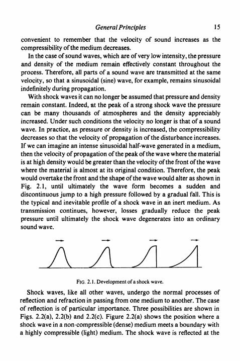
With shock waves it can no longer be assumed that pressure and densityremain constant. Indeed, at the peak of a strong shock wave the pressurecan be many thousands of atmospheres and the density appreciablyincreased. Under such conditions the velocity no longer is that of a soundwave. In practice, as pressure or density is increased, the compressibilitydecreases so that the velocity of propagation of the disturbance increases.If we can imagine an intense sinusoidal half-wave generated in a medium,then the velocity of propagation of the peak of the wave where the materialis at high density would be greater than the velocity of the front of the wavewhere the material is almost at its original condition. Therefore, the peakwould overtake the front and the shape of the wave would alter as shown inFig. 2.1, until ultimately the wave form becomes a sudden anddiscontinuous jump to a high pressure followed by a gradual fall. This isthe typical and inevitable profile of a shock wave in an inert medium. Astransmission continues, however, losses gradually reduce the peakpressure until ultimately the shock wave degenerates into an ordinarysound wave.
A AFIG. 2.1. Development of a shock wave.
Shock waves, like all other waves, undergo the normal processes ofreflection and refraction in passing from one medium to another. The caseof reflection is of particular importance. Three possibilities are shown inFigs. 2.2(a), 2.2(b) and 2.2(c). Figure 2.2(a) shows the position where ashock wave in a non-compressible (dense) medium meets a boundary witha highly compressible (light) medium. The shock wave is reflected at the

16 High Explosives
Before
(a)
j TMSiM
(W
TCMnrenitn
Before After
Tension
FIG. 2.2. Reflection of shock waves, (a) Shock wave in denser medium,(b) Matched media, (c) Shock wave in lighter medium.
interface as a rarefaction wave, provided that the tensile strength of themedium makes this possible. Figure 2.2(c) shows the extreme contrast tothis where a wave in a compressible medium meets a medium of lowcompressibility. In this case again the wave is reflected, but as acompression wave rather than a rarefaction wave. Case 2.2(b) is theintermediate case where the media have similar compressibility and in thiscase, and this case alone, is the shock wave transmitted across theboundary without alteration.
A shock wave in an inert medium is not propagated indefinitely without

General Principles 17
change because rarefaction waves can always overtake the pressure waveand reduce the peak pressure until the conditions of a sound wave arereached. For a stable shock wave to be maintained, a source of energymust be available which will enable the wave to be propagated withoutrarefaction waves occurring. This is what happens when detonationoccurs in an explosive.
When a detonation wave passes through an explosive, the first effect iscompression of the explosive to a high density. This is the shock waveitself. Then reaction occurs and the explosive is changed into gaseousproducts at high temperature. These reaction products act as acontinuously generated piston which enables the shock wave to bepropagated at a constant velocity. The probable structure of thedetonation zone is illustrated in Fig. 2.3.
FIG. 2.3. Structure of detonation wave.
Mathematically, the following three equations can be written downrepresenting respectively the application of the laws of conservation ofmass, momentum and energy.
Mass:D D-W,
(2)
Momentum:D2
(3)
Energy: E1 + D2 + P1V1 = E2 + ±(D- W2)2 + p2v2 (4)
18 High Explosives
where D = velocity of detonation,W2 = velocity of material behind the wave, relative to that in
front,v = specific volume,p = pressure,E = specific internal energy,
and subscripts 1 and 2 relate to the initial and final states of the explosiverespectively.
It will be noted that E1 is the specific internal energy of the unreactedexplosive, whereas E2 is the specific internal energy of the explosionproducts at pressure p2 and specific volume V2. These equations arededuced from physical laws only and are independent of the nature orcourse of the chemical reaction involved.
Equations (2) and (3) can be solved to give the following equations for Dand for W2-.
AV(V1-V2)] (5)
W2 = (V1 - V2) \/[(p2 - P1V(Vi - V2)] (6)
It will be noted that asp2 is greater thanpj, V2 must be less than v,, and W2
(known as the streaming velocity) is positive, meaning that the explosionproducts travel in the same direction as the detonation wave. This positivestreaming velocity is a characteristic and identifying property of adetonation wave.
These are the basic equations of the hydrodynamic theory ofdetonation. If p2 and V2 can be determined, they enable the remainingfeatures of the detonation wave to be calculated. Unfortunately p2 and V2
relate to conditions in the detonation wave and not to the lower pressureconditions which the explosion products would reach at equilibrium in, forexample, a closed vessel. Therefore, further calculations are needed todetermine p2 and V2.
In studying detonation, it is convenient to use diagrams of the typeillustrated in Fig. 2.4. In these, the pressure is plotted over the specificvolume. The original explosive corresponds to point A. The reactionproducts are represented by the curve BC, known as the Rankine-

General Principles 19
RG. 2.4. Rankine-Hugoniot diagram.
Hugoniot curve, which represents all possible points in the area whichsatisfy the chemical equilibria and entropy conditions of the explosivereaction products. It is a locus which is defined by, and can be calculatedfrom, the energy equation — equation (4). (p2, V2) must therefore be a pointon this line. As noted above, V2 must be less than V1, so the point must lie onthe part of the curve BD. To determine exactly where the point (p2, V2) liesin the curve BD requires difficult arguments which are not reproducedhere, but which show that the point can be obtained by drawing a tangentfrom A to the curve; this is known as the Chapman-Jouguet condition,and the tangent is the Raleigh line. Thus the point/shown in Fig. 2.4 givesP2 and V2. Substituting these values in equation (5) gives the calculateddetonation velocity.
The major difficulty in applying this hydrodynamic theory ofdetonation to practical cases lies in the calculation of E2, the specificinternal energy of the explosion products immediately behind thedetonation front, without which the Rankine-Hugoniot curve cannot bedrawn. The calculations require a knowledge of the equation of state of thedetonation products and also a full knowledge of the chemical equilibriainvolved, both at very high temperatures and pressures. The first equationof state used was the Abel equation
P2(V2- a) = n2RT2 (7)

20 High Explosives
where a is a constant, n2 is the number of gramme-molecules of gas, and Ris the gas constant, but this becomes inaccurate for explosives with adensity above O-1 g ml"1. Probably the most successful equation so farused is that by Paterson and is a virial type equation as follows
P2 = H2RT(I + bp + 0-62562 p2 + 0-28763 p3 + O-193A4 p4) (8)
where b is a constant.Typical results are given in Table 2.1 for pure explosives which give
only gaseous products.A semi-empirical equation was introduced by Kistiakowsky and Wilson
and took the following form:
P2V2 = n2RT(l-xQ P*) where x = pkT~a
TABLE 2.1 Calculated Properties of Explosive Compounds
Compound
NitroglycerinePETNTetrylTNTNitroguanidineAmmonium
nitrate
Density
(gmP)
1-601-501-501-500-60
1-00
Energy
(Jg"1)
62835881581054132658
1580
Streamingvelocity
(ms'1)
15501550132011401027
832
Velocity of detonation(ms"1)
Calculated
80608150755064804040
3460
Observed
80007600730067003850
—
The constants a and P were first chosen to give the best fit to experimentaldetonation velocity measurements for a wide variety of materials. Theyhave more recently been revised by Cowan and Fickett to give betteragreement with experimentally measured detonation pressures. Fornumerous other approaches to the problem of the equation of state underdetonation conditions, readers are referred to the book by Cook and apaper by Jacobs.
Commercial explosives frequently contain salts, or give other solidresidues. In calculations these cause difficulties, as it is not certain whethersolid ingredients reach equilibrium with the explosion products. In thecalculations it is possible either to assume thermal equilibrium, or to
General Principles 21
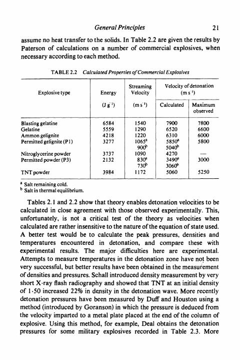
assume no heat transfer to the solids. In Table 2.2 are given the results byPaterson of calculations on a number of commercial explosives, whennecessary according to each method.
TABLE 2.2 Calculated Properties of Commercial Explosives
Explosive type
Blasting gelatineGelatineAmmon gelignitePermitted gelignite (Pl)
Nitroglycerine powderPermitted powder (P3)
TNT powder
Energy
(Jg1)
6584555942183277
37372132
3984
StreamingVelocity
(ms'1)
1540129012201065a
900^1090830s
730^1172
Velocity of detonation(ms'1)
Calculated
790065206310585O3
5040^42703490s
3060^5060
Maximumobserved
7800660060005800
3000
5250
a Salt remaining cold.b Salt in thermal equilibrium.
Tables 2.1 and 2.2 show that theory enables detonation velocities to becalculated in close agreement with those observed experimentally. This,unfortunately, is not a critical test of the theory as velocities whencalculated are rather insensitive to the nature of the equation of state used.A better test would be to calculate the peak pressures, densities andtemperatures encountered in detonation, and compare these withexperimental results. The major difficulties here are experimental.Attempts to measure temperatures in the detonation zone have not beenvery successful, but better results have been obtained in the measurementof densities and pressures. Schall introduced density measurement by veryshort X-ray flash radiography and showed that TNT at an initial densityof 1-50 increased 22% in density in the detonation wave. More recentlydetonation pressures have been measured by Duff and Houston using amethod (introduced by Goranson) in which the pressure is deduced fromthe velocity imparted to a metal plate placed at the end of the column ofexplosive. Using this method, for example, Deal obtains the detonationpressures for some military explosives recorded in Table 2.3. More
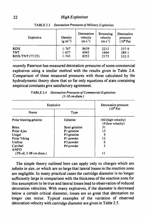
22 High Explosives
TABLE 2.3 Detonation Pressures of Military Explosives
Explosive
RDXTNTRDX/TNT (77/23)
Density(gmP)
1-7671-6371-743
Detonationvelocity(ms'1)
863969428252
Streamingvelocity(ms'1)
221316642173
Detonationpressure(1O8Pa)
337-9189-1312-5
recently Paterson has measured detonation pressures of some commercialexplosives using a similar method with the results given in Table 2.4.Comparison of these measured pressures with those calculated by thehydrodynamic theory show that so far only equations of state containingempirical constants give satisfactory agreement.
TABLE 2.4 Detonation Pressures of Commercial Explosives(3'lScmdiam.)
Explosive
Name
Polar blasting gelatine
BelexPolar AjaxUnigelPolar VikingUnifraxCarribelANFO
(2%oil,5-08cmdiam.)
Type
Gelatine
Semi-gelatineP 1 gelatineP3 gelatineP 1 powderP3 powderP4 powder
V i v faf
160 (high velocity)1 9 (low velocity)31139
1265
11
Detonation pressure
The simple theory outlined here can apply only to charges which areinfinite in size, or which are so large that lateral losses in the reaction zoneare negligible. In many practical cases the cartridge diameter is no longersufficiently large in comparison with the thickness of the reaction zone forthis assumption to be true and lateral losses lead to observation of reduceddetonation velocities. With many explosives, if the diameter is decreasedbelow a certain critical diameter, losses are so great that detonation nolonger can occur. Typical examples of the variation of observeddetonation velocity with cartridge diameter are given in Table 2.5.
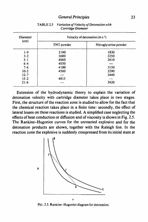
General Principles
T AB LE 2.5 Variation of Velocity of Detonation withCartridge Diameter
23
Diameter(cm)
1-93-25-16-47-6
10-212-715-221-6
Velocity of detonation (m s"1)
TNT powder
319036804060403041004560—
4815—
Nitroglycerine powder
183022502610—
315032903440—
3920
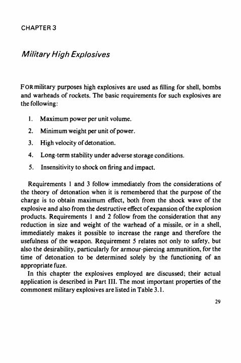
Extension of the hydrodynamic theory to explain the variation ofdetonation velocity with cartridge diameter takes place in two stages.First, the structure of the reaction zone is studied to allow for the fact thatthe chemical reaction takes place in a finite time: secondly, the effect oflateral losses on these reactions is studied. A simplified case neglecting theeffects of heat conduction or diffusion and of viscosity is shown in Fig. 2.5.The Rankine-Hugoniot curves for the unreacted explosive and for thedetonation products are shown, together with the Raleigh line. In thereaction zone the explosive is suddenly compressed from its initial state at
RG. 2.5. Rankine-Hugoniot diagram for detonation.

24 High Explosives
point A to a state at point F. Reaction then occurs with the pressure fallingalong the line FJ until at the end of the reaction zone a point J is reachedand stable detonation conditions arrived at. The actual shape of thepressure wave is shown in Fig. 2.6 where the so-called Neumann peak oftwice the detonation pressure is shown. A more complete solution byHirschfelder and Curtiss shows that the effects of viscosity and thermaltransfer by diffusion and conduction are to reduce the magnitude of theNeumann peak and the steepness of the initial increase in pressure. Onesuch solution is sketched in Fig. 2.6 where a first order chemical reactionhas been assumed. The shape will depend, however, on the magnitude ofthe heat losses and in some cases the initial peak need not occur at all.Some evidence for the existence of the Neumann peak has been obtainedas, for example, by Duff and Houston. In their measurements the peakpressure reached was 42% abovep2.
Simple theory
Complete solution
FIG. 2.6. Calculated shape of detonation wave head.
Cook has propounded a rather different theory of the nature of thereaction zone. He emphasises that the demonstrable electricalconductivity of the detonation wave is evidence of a high thermalconductivity. Both these effects are ascribed to ionisation of the explosionproducts. In terms of the reaction zone, this implies a steady pressure withno peaks.
Theoretical considerations of charges of limited diameter have takenone of two forms. The former assumes that the effects are best described asa result of the curvature of the wave front in the explosive (this can bedemonstrated experimentally), or of reduction of the driving pressure bylateral expansion. Solutions of this type have been given by Eyring and co-workers and by Jones. Alternatively, the variation in velocity of

General Principles 25
detonation can be explained as a result of incomplete reaction during theactual detonation wave. Explanations of this type have been put forwardby Cook and also by Hino. The following equations illustrate thedependence of detonation velocity on charge diameter according to thevarious theories.
Eyring, Powell, Duffey and Parlin:
D/D0=l-z/d for z/d< 0-25
Jones (cf. Jacobs):
(DfD0)2= 1 -3-2(z/d)2 .
Cook:
where d = diameter of charge,z = reaction zone thickness,a = constant,d' =d — 0-6 cm,t = reaction time.
The thickness of the reaction zone in high explosives is usually in the range1-10 mm.
Liquid nitroglycerine and gelatinous explosives made from it can exhibittwo stable velocities of detonation, of approximately 2000 and 8000 m s"1
respectively. The phenomenon is complicated by the occurrence of airbubbles in such explosives and has not yet been completely explained.
The theory of detonation has also been extended to study the process ofinitiation of reaction by the commonest means used in practice, namely, bythe shock wave arising from another high explosive. Campbell, Davis andTravis have studied the initiation by plane shock waves of homogeneousexplosives, particularly nitromethane. Initiation occurs at the boundary ofthe explosive after an induction period which is of the order of amicrosecond and which depends markedly on initial temperature. Duringthe induction period the shock wave has proceeded through the explosiveand compressed it. The detonation initially in compressed explosive has avelocity some 10% above normal, but the detonation soon overtakes the

26 High Explosives
shock front and the detonation velocity falls abruptly to the normal value.The process is shown in Fig. 2.7(a). These results can be explainedadequately on the basis of thermal explosion theory as developed, forexample, by Hubbard and Johnson.
Direction ofrotation of camera
incidentshock wave
High velocity ^^^ \^ / Accelerating wave
(a) Homogeneous (b) Heterogeneousexplosive explosive
FIG . 2.7. Initiation of detonation in explosives, as shown in a rotatingmirror camera.
Even slight lack of homogeneity in explosives or shock wave form leadsto an alternative mode of initiation characteristic of ordinary military orcommercial explosives in solid or gelatinous form. This process has beenstudied by Campbell, Davis, Ramsay and Travis and is depicted in Fig.2.7(b). The shock wave first proceeds through the explosive with slowacceleration. After a few centimetres there is abrupt transition todetonation at normal velocity. The distance at which transition occurs isindependent of temperature but can be reduced by (i) increasing thepressure of initiating shock, (ii) increasing the fineness of the activeingredients, or (iii) for powder explosives reducing the loading density.Deliberate introduction of centres of heterogeneity, such as air bubbles orbarium sulphate, is well known to reduce the distance. These resultscannot be explained by general thermal explosion as there is insufficientenergy to give the required temperature rise. They can be explained on thebasis of reaction at local centres or "hot spots".

General Principles 27
A similar explanation had already been given for the initiation ofexplosives by impact and friction. These phenomena have been extensivelystudied, particularly by Bowden and his school. Their work demonstratedtwo particularly important modes of initiation:
1. By adiabatic compression of gas. This is particularly noticeable inliquid explosives such as nitroglycerine, where ever} the moderatecompression of small gas bubbles can readily lead to initiation ofthe explosive.
2. By the development of hot spots by friction. This is shownparticularly by the effect of added materials of a gritty nature. Forinitiation to occur, the melting point of the grit must be above alimiting temperature dependent on the explosive. Initiation isfavoured by a low thermal conductivity and also by a high hardnessvalue.
Burning of high explosives can on occasion lead to detonation,particularly if large quantities are involved. In close bomb tests Wachtell,McKnight and Shulman find a reproducible pressure above which burningbecomes progressively faster than would be expected from strand burnertests (see p. 179). For TNT this pressure is about 45 MPa, but forpropellants much higher. They regard this characteristic pressure as ameasure of the liability to detonation.
The external effects of a detonating explosive are of two types, due in thefirst place to the shock wave and in the second place to the expansion of thedetonation products. The detonation wave reaching the end of a cartridgeis propagated into the further medium, whether this be air, rock, or water.Because of the positive streaming velocity of the detonation wave, theeffects are particularly strong at the terminal end of the cartridge.Although a cartridge detonated in air can produce a shock wave with avelocity even higher than that of the explosive itself, the energy in this waveis relatively small. If the explosive completely fills a metal case, or aborehole in rock, much greater amounts of energy can penetrate into thesurrounding media. In either case, however, by far the greater proportionof the energy of the explosive is liberated during the expansion of thegaseous products and it is in general this work of expansion which causesthe explosive to have its desired effect. The amount of energy availablefrom an explosive for this purpose can be calculated by integrating themechanical work done during the expansion of the products to

28 High Explosives
atmospheric pressure. More often, however, it is measured by some
practical test (cf. Chapter 6).
A special simple case of work done by an explosive is observed when
charges are fired under water. The observed effects are first a shock wavewhich is transmitted through the water, secondly an expanding bubble of
gas. This bubble expands to a maximum size and then collapses, to expandagain and vibrate until the energy has been dissipated. Rather more thanhalf the energy remaining available in the gas is transmitted through thewater during each expansion of the bubble. These phenomena are
described in detail by Cole.
References
Historical
BERGENGREN, E.,AlfredNobel Nelson, London, I960.MAC DONALD , G. W., Historical Papers on Modern Explosives. Whittaker, London, 1912.SCHUCK, H. and SOHLMAN, R., The Life of Alfred Nobel. Heinemann, London, 1929.
Genera]
BOWDEN , F. P. and YOFFE, A. D., The Initiation and Growth of Explosion in Liquids andSolids. University Press, Cambridge, 1952.
COLE, R. H., Underwater Explosion. Princeton University Press, New Jersey, 1948.COOK , M. A., The Science of High Explosives. Reinhold, New York, 1958.JACOBS , S. J., Am. Rocket Soc. J. 30,151 (1960).TAYLOR, J., detonation in Condensed Explosives. Clarendon Press, Oxford, 1952.ZELDOVICH, J. B. and KOMPANEETS, A. S., Theory of Detonation. Academic Press, New
York, 1960.
Specific
CAMPBELL, A. W., DAVIS, W. C., RAMSAY, J. B. and TRAVIS, J. R., Physics of Fluids, 4,511(1961).
CAMPBELL , A. W., DAVIS , W. C. and TRAVIS, J. R., Physics of Fluids, 4,498 (1961).COWAN, R. O. and FICKETT, W.,/. Chem. Phys. 24,932 (1956).DEAL, W. E.,/. Chem. Phys. 27,796 (1957).DUFF, R. E. and HOUSTON, E. J. Chem. Phys. 23,1268 (1955).EYRING, H., POWELL, R. E., DUFFEY, C. H. and PARLIN, R. B., Chem. Rev. 45,69 (1949).HiNO,R.,/./nd.Expl.Soc.,/apan, 19,169(1958).HUBBARD, H. W. and JOHNSON, M. H.,J.Appl.Phys. 30,765 (1959).JONES , H., Proc. Roy. Soc. A 189,415 (1947).KISTIAKOWSKY, G. B., and WILSON, E. B., OSRD No. 114 (1941).PATERSON , S., Research 1,221 (1948).SCHALL, R.,NobelHefte, 21,1 (1955).WACHTELL, S., MCKNIGHT, C. E. and SHULMAN, L., Picatinny Arsenal Technical Rep.
DB-TR: 3-61 (1961).
CHAPTER 3
Military High Explosives
F OR military purposes high explosives are used as filling for shell, bombsand warheads of rockets. The basic requirements for such explosives arethe folio wing:
1. Maximum power per unit volume.
2. Minimum weight per unit of power.
3. High velocity of detonation.
4. Long-term stability under adverse storage conditions.
5. Insensitivity to shock on firing and impact.
Requirements 1 and 3 follow immediately from the considerations ofthe theory of detonation when it is remembered that the purpose of thecharge is to obtain maximum effect, both from the shock wave of theexplosive and also from the destructive effect of expansion of the explosionproducts. Requirements 1 and 2 follow from the consideration that anyreduction in size and weight of the warhead of a missile, or in a shell,immediately makes it possible to increase the range and therefore theusefulness of the weapon. Requirement 5 relates not only to safety, butalso the desirability, particularly for armour-piercing ammunition, for thetime of detonation to be determined solely by the functioning of anappropriate fuze.
In this chapter the explosives employed are discussed; their actualapplication is described in Part III. The most important properties of thecommonest military explosives are listed in Table 3.1.
29

30 High Explosives
T AB LE 3.1 Properties of Military Explosives
Explosive
TNTPETNRDXTetryl
m.p.(°C)
80-7141-3204129
Density(gmH)
1-631-771-731-6
Weight strength% Blastinggelatine8
6797
10084
Maximum detonationvelocity (m s~ ')
6950830085007500
a See p. 62.
TRINITROTOLUENE
Trinitrotoluene is the 2,4,6-isomer of the following constitution:
The starting material is pure toluene, specially free from unsaturatedaliphatic hydrocarbons. This is nitrated in several stages to avoidoxidation side reactions which occur when toluene itself is mixed withstrong nitrating acids. The traditional process employed three nitratingstages; as an example the nitrating acids used in France are given in Table3.2.
TABLE 3.2 French Nitrating Acids for TNT Manufacture
Nitric acid wt. %Sulphuric acid wt. %Water wt. %
1 st stage
285616
2nd stage
3261
7
3rd stage
4949
2
During and since the Second World War, the three-stage process hasbeen replaced by continuous methods of nitration employing a largernumber of stages. In these, the chemical engineering can differ widely, butin principle toluene enters the process at one end and trinitrotoluene is
Military High Explosives 31
produced at the other. The nitrating acid flows in the opposite direction,being fortified as required at various points. One of the most importantfactors is stirring in the nitrators, as this markedly affects the speed andcompleteness of nitration, particularly in the later stages. For a discussionof these methods the reader is referred to a book by Urbanski.
The crude product contains isomers other than that required and alsonitrated phenolic compounds resulting from side reactions. The usualmethod of purification is to treat the crude product with sodium sulphite,which converts asymmetric trinitro compounds to sulphonic acidderivatives, and to wash out the resulting soluble products with alkalinewater. The purity of the product is determined by the melting point, theminimum value for Grade I TNT commonly being 80-20C. Unlessadequate purity is achieved, slow exudation of impurities can occur duringstorage and the TNT then becomes insensitive.
TNT is relatively safe to handle and of low toxicity. It is, therefore,preferred to picric acid and ammonium picrate which give sensitivecompounds with a variety of metals, and to trinitrobenzene orhexanitrodiphenylamine which are highly toxic.
TNT contains insufficient oxygen to give complete combustion of thecarbon on detonation. It can, therefore, usefully be mixed with ammoniumnitrate, which has an excess of oxygen. The resulting explosives, known asamatols, are more powerful and cheaper than TNT itself, but in generalhave a lower velocity of detonation. A proportion of 60% ammoniumnitrate is perhaps the commonest of these compositions.
PENTAERYTHRITOL TETRANITRATE(PETN, PENTHRITE)
This material has the following formula:
O2NOH2Cv .CH2ONO2
^
O2NOH2C' ^CH2ONO2
Pentaerythritol is made commercially by the reaction of formaldehyde andacetaldehyde in the presence of alkali. It can be nitrated by adding it tostrong nitric acid at temperatures below about 3O0C. An excess of nitric

32 High Explosives
acid is used so that the refuse acid from the reaction contains at least 75%nitric acid, as refuse acids of lower strength can be unstable. The washedproduct is reprecipitated from acetone to give a suitable crystal size andadequate stability on storage. PETN is always transported wet with water,and dried only as required.
PETN, discovered in 1895, is a solid melting at 1410C and is a verypowerful explosive. It is very stable both chemically and thermally.
Pure PETN is too sensitive to friction and impact for direct applicationfor military purposes. It can usefully be mixed with plasticisednitrocellulose, or with synthetic rubbers to obtain plastic or mouldableexplosives. The commonest application, however, is in conjunction withTNT in the form of pentolites. Pentolites are usually obtained byincorporating PETN into molten TNT. A small amount of the PETN goesinto solution, but the bulk remains suspended in the liquid and the wholemix can suitably be used in preparing cast charges. Pentolites containing20-50% PETN are the commonest in practice.
RDX (CYCLOTRIMETHYLENE-TRINITRAMINE,CTMTN, CYCLONITE, HEXOGEN)
RDX has the following formula:
NO2
O2N-N.2 N
H2
It is made by the nitration of hexamine (hexamethylenetetramine), itselfprepared from formaldehyde and ammonia. Hexamine was originallynitrated with a large excess of concentrated nitric acid at temperaturesbelow 3O0C and the product recovered by adding the reaction liquor to anexcess of chilled water. Later the yield was improved by addingammonium nitrate to the reaction as this reacts with the liberatedformaldehyde. A much-used process converts the hexamine first to itsdinitrate, which is then reacted with ammonium nitrate, nitric acid andacetic anhydride (the last reagent being re-formed from the product by use
Military High Explosives 3 3
of ketene). The RDX can be isolated by evaporation of the mother liquor,and then purified by washing.
RDX is a white solid melting at 2040C. Originally discovered byHenning in 1899, it attained military importance during the Second WorldWar owing to its lower sensitiveness than PETN. It is very stable, bothchemically and thermally.
RDX may be used alone in pressed charges, although for this purposetetryl is a more general choice. For shell and bomb fillings it is too sensitivealone to initiation by impact and friction and is either desensitised withwax, or else used like PETN in admixture with TNT. RDX may also becompounded with mineral jelly and similar materials to give a usefulplastic explosive.
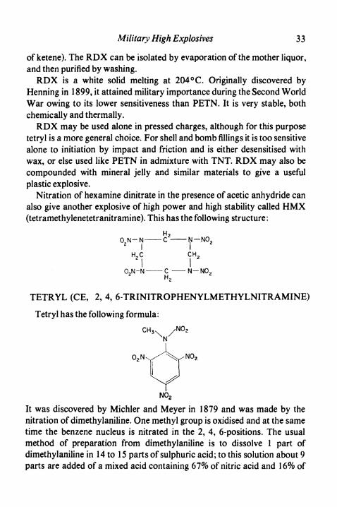
Nitration of hexamine dinitrate in the presence of acetic anhydride canalso give another explosive of high power and high stability called HMX(tetramethylenetetranitramine). This has the following structure:
H2O.N-N C N-NO22
H2C
-CH,
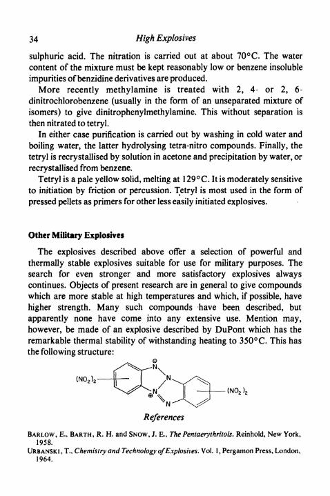
TETRYL (CE, 2, 4, 6-TRINITROPHENYLMETHYLNITRAMINE)
Tetryl has the following formula:
O2N
NO2
It was discovered by Michler and Meyer in 1879 and was made by thenitration of dimethylaniline. One methyl group is oxidised and at the sametime the benzene nucleus is nitrated in the 2, 4, 6-positions. The usualmethod of preparation from dimethylaniline is to dissolve 1 part ofdimethylaniline in 14 to 15 parts of sulphuric acid; to this solution about 9parts are added of a mixed acid containing 67% of nitric acid and 16% of
34 High Explosives
sulphuric acid. The nitration is carried out at about 7O0C. The watercontent of the mixture must be kept reasonably low or benzene insolubleimpurities of benzidine derivatives are produced.
More recently methylamine is treated with 2, 4- or 2, 6-dinitrochlorobenzene (usually in the form of an unseparated mixture ofisomers) to give dinitrophenylmethylamine. This without separation isthen nitrated to tetryl.
In either case purification is carried out by washing in cold water andboiling water, the latter hydrolysing tetra-nitro compounds. Finally, thetetryl is recrystallised by solution in acetone and precipitation by water, orrecrystallised from benzene.
Tetryl is a pale yellow solid, melting at 1290C. It is moderately sensitiveto initiation by friction or percussion. Tetryl is most used in the form ofpressed pellets as primers for other less easily initiated explosives.
Other Military Explosives
The explosives described above offer a selection of powerful andthermally stable explosives suitable for use for military purposes. Thesearch for even stronger and more satisfactory explosives alwayscontinues. Objects of present research are in general to give compoundswhich are more stable at high temperatures and which, if possible, havehigher strength. Many such compounds have been described, butapparently none have come into any extensive use. Mention may,however, be made of an explosive described by DuPont which has theremarkable thermal stability of withstanding heating to 35O0C. This hasthe following structure:
(NO2 )2-
- (NO 2 J 2
\^References
BARLOW, E., BARTH, R. H. and SNOW, J. E., The Pentaerythritols. Reinhold, New York,1958.
URBANSKI , T., Chemistry and Technology of Explosives. Vol. 1, Pergamon Press, London,1964.

CHAPTER 4
Manufacture of Commercial Explosives
Ammonium Nitrate
Ammonium nitrate is the cheapest source of oxygen available forcommercial explosives at the present time. It is used by itself inconjunction with fuels, or to give more sensitive explosives in admixturewith solid fuels and sensitisers such as nitroglycerine and TNT. It is,therefore, a compound of particular importance for the explosivesindustry.
Ammonium nitrate is made by the neutralisation of nitric acid withammonia. The details of these processes are given in other volumes of thisseries. For particular application in explosives, ammonium nitrate isrequired in specialised forms, of which the following two are the mostimportant.
For use in explosives sensitised by high explosive ingredients,ammonium nitrate should be of a dense and non-absorbent character.Whilst absorbent ammonium nitrate can be employed, it tends to be oflower density and therefore gives lower bulk strengths to the finalexplosive; it also absorbs a larger amount of nitroglycerine and requiresmore of this expensive ingredient to give a suitable gelatinous consistency.Dense ammonium nitrate is made either by crystallisation from solution,followed, if necessary, by grinding and screening, or more generally byspraying a melt containing at least 99-6% of ammonium nitrate down ashort tower. The spray process produces spherical particles which can betaken from the bottom of the tower and cooled with the minimum ofdrying. For many years setting of ammonium nitrate, due to absorption ofmoisture and subsequent temperature change or drying out, led to cakingof the salt and corresponding difficulties in handling. Nowadays this isovercome by adding either crystal habit modifiers which cause
35

36 High Explosives
recrystallised ammonium nitrate to have low physical strength, or else byother additives which appear to lubricate the surface of the crystals. In thisway, provided storage conditions are reasonable, ammonium nitrate canbe kept in a condition suitable for easy mechanical handling.
For use in conjunction with fuel oil an absorbent form of ammoniumnitrate is required. This is produced by spraying a hot 95% solution down ahigh tower, so that some drying occurs before the spherical droplets reachthe bottom. The resultant spheres must be carefully dried and cooled toprevent breakdown in handling. They are then usually coated with amixture of diatomaceous earth and a wetting agent in approximateproportions of 0-5% and 0-05% respectively. The bulk density of theproduct is about 0-7 to 0-8 compared with about 1 for the dense materialand it will absorb 7-8% of light oil without appearing unduly wet.Ammonium nitrate "prills" of this type were originally made in Canada,but have since become popular in many parts of the world.
Ammonium nitrate undergoes phase changes at 32° and 830C andmelts at 170°. It is not normally considered an explosive when pure,although under suitable conditions it can be made to detonate. Whenmixed with small amounts of organic matter it becomes much moresensitive and several serious explosions have occurred with such mixtures.The limit of organic matter so far allowed in the U.K. is 0-05%, but insome countries O-1% is accepted.
Nitroglycerine
Nitroglycerine, or glycerine trinitrate, has the following formula:
H2CONO2
IHCONO2
IH2CONO2
It was discovered by Sobrero in 1847, but was developed to a commercialscale by Nobel. It has for a long time been, and still is, the most importantsensitiser for commercial explosives.
Nitroglycerine is made by reacting purified glycerine with a mixed acid

Manufacture of Commercial Explosives 3 7
containing nitric acid, sulphuric acid and water. The temperature must becarefully controlled and the product when separated from the refuse acidhas to be washed free from surplus acid before it becomes stable. It is asensitive explosive, easily initiated by certain forms of friction and impact.For this reason and because of the importance of economic production ofthe compound, considerable study has gone into the design and operationof nitroglycerine plants.
Originally nitroglycerine was made by batch processes in whichglycerine was added slowly to mixed acid in large vessels containingcooling coils. The acid contained 40-50% nitric acid with the remaindersulphuric acid. The worker controlled the flow of glycerine so that themaximum temperature allowed, usually 180C, was not exceeded.Nitroglycerine, being less dense than the refuse acid, separated to the topand could be skimmed off. It was then washed with water and dilutesodium carbonate solution in air-stirred vessels before being allowed tostand and was then weighed for use. The nitration, weighing and washingwere usually carried out in separate houses. Should any untoward incidentoccur during nitration, the whole mixture of acid and nitroglycerine couldbe discharged rapidly into a large volume of water in a drowning tank. Aslarge quantities of nitroglycerine were involved, accidents when theyhappened were usually severe, and for this reason continuous processesinvolving smaller amounts of nitroglycerine in process at any time wereevolved.
The first continuous process was that of Schmid in which glycerine andmixed acid were fed continuously into a specially designed, stirred andcooled nitrator; cooling was by chilled brine. The mixture from the nitratorwent into a separator of special design from which the nitroglycerineoverflowed from the top and refuse acid was removed from the bottom.The crude nitroglycerine was then washed in a series of columns andflowed by gravity to the weighing house.
A more recent process was developed by Biazzi and is somewhat similarin general principle to the Schmid process. It uses, however, improvedchemical engineering designs and in this way is suited to operation byremote control.
The most recent process was introduced by Nitroglycerine AB (NAB)in Sweden and has a radically different system of nitration. An injector isused for mixing glycerine and nitrating acid and the nitration is carried out

3 8 High Explosives
in a tube. The mixture of acid and nitroglycerine passes through a tubularcooler and is then separated in a centrifugal separator. The short residencetime makes possible the use of high nitration temperatures and thethroughput of the plant is high. Nevertheless, only very limited amounts ofnitroglycerine are in process at any time.
Nitroglycerine can detonate in pipes of diameter down to approximately5 mm. In nitroglycerine manufacture there is, therefore, an inherentdanger of transmission of detonation from one manufacturing house toanother in the series. Even a pipe which has been emptied of nitroglycerinecan have on it a skin of the product sufficient to enable transmission ofdetonation from one end of the pipe to the other. To prevent the spread ofan accident it is now usual to transfer nitroglycerine as a non-explosiveemulsion in an excess of water. Such emulsion transfer is particularlyconvenient with the NAB process, as the emulsion transfer lines can alsocarry out the necessary process of washing and purification.
Nitroglycerine is a viscous yellow liquid which freezes at 13-20C to asensitive solid explosive. Because of the danger of freezing, purenitroglycerine is now only rarely used in making explosives. The commonpractice is to mix ethylene glycol with the glycerine and nitrate the mixtureso as to give a product which contains from 20 to 80% of ethylene glycoldinitrate. For most climates any mixtures in this range give satisfactoryresults, although under the very coldest conditions the extremes should beavoided.
Nitroglycerine when heated rapidly explodes somewhat above 20O0C,but on storage it proves unstable at temperatures exceeding 70-8O0C. Thethermal decomposition products are very complex. In large quantities ofwater it is hydrolysed to nitric acid and glycerine, but this reaction is veryslow at ordinary temperatures. Nitroglycerine has a marked physiologicaleffect producing dilation of the arteries and severe headaches. Ethyleneglycol dinitrate, or nitroglycol, has even more severe effects and with ahigher vapour pressure is more prone to cause unpleasant reactions. It isalso more toxic than nitroglycerine. These effects call for precautionsduring manufacture, but are not severe enough to affect the user.
Nitrocellulose
Nitrocellulose is used in commercial high explosives mainly to thicken

Manufacture of Commercial Explosives 39
the nitroglycerine in the preparation of gelatine and semi-gelatine compo-sitions. The raw material is cotton. Nitration is carried out with mixed acidcontaining nitric and sulphuric acids and a proportion of water adjustedso that the nitrogen content of the nitrocellulose produced is about 12-2%.The relationship between the nitrogen content of the product and the acidleft after nitration is shown in the ternary diagram (Fig. 4.1). Nitrators
O "Industrial" NC, 11-0% NO "Industrial" HC, 12-0% NC Guncotton, 13-1%
Guncotton, 13-5%
Zone oftechnicalnitrations
FIG. 4.1. Cellulose nitration diagram.
40 High Explosives
may be stirred or unstirred, depending on the nitration method used andthe particular type of nitrocellulose required. After nitration, excess acid isremoved in a centrifuge and the acid-wet nitrocellulose drowned in astream of water. The nitrocellulose is stabilised by treating it with hotacidic water followed by hot dilute sodium carbonate solution. It is thenpulped to a fine form so that it will dissolve rapidly in nitroglycerine.
The nature of the nitrocellulose used is of particular importance inexplosives if freedom from exudation of free nitroglycerine during storageis to be avoided. Nitroglycerine is only a poor solvent for nitrocelluloseand stability of the gel depends on continuous formation and breakdownof gelled structures. The distribution of nitrogen content and viscosity,even in the individual fibres of the nitrocellulose, is therefore of paramountimportance.
Nitrocellulose is usually handled wet and containing approximately30% of water. Under these conditions it can be considered as a non-explosive material when the nitrogen content does not exceed 12-6%.More highly nitrated cellulose is known as guncotton and is explosive evenwhen moderately wet. When dry, nitrocellulose of all types is an extremelysensitive and dangerous explosive. Dry nitrocellulose is required for use incertain types of explosives and is then prepared by slow drying of the wetmaterial in a current of warm air.
TNT
The preparation and properties of TNT are described in Chapter 3.Next to nitroglycerine, TNT is the most important sensitising constituentof commercial explosives. For such purposes it does not need to have thehigh purity demanded for the military product, but otherwise the materialis identical.
In commercial explosives TNT has the advantage of greater safety inhandling than nitroglycerine and also less physiological effect. On theother hand, it gives explosives which tend to be unreliable under certainconditions. Its use is therefore tending to diminish in Britain, although insome countries it is being applied in slurried explosives for large boreholes(see p. 56).

Manufacture of Commercial Explosives 41
Powder Explosives
The preparation of powder explosives is in essence simple. In the case ofmixtures of ammonium nitrate and fuel oil in particular, the onlyrequirement is a method of mixing which does not cause undue breakdownof the absorbent grains of ammonium nitrate. Hand mixing is employedfor small quantities, otherwise some form of rotating container or gentlystirred vessel.
Powder explosives containing nitroglycerine are naturally more difficultto manufacture. Full precautions against explosion must be taken at allstages. The mixing equipment is generally a vessel containing a stirrer on ahorizontal axis, or with two parallel stirrers as in the familiar WernerPfleiderer type. In modern installations addition of ingredients and mixingand emptying operations are frequently carried out by remote control. Theprocess consists simply of adding the ingredients to the equipment andstirring until adequately mixed, usually for a period of about 15 min. Themixed explosive is then cartridged, and for this purpose a variety ofmachines is available. In the commonest types, pre-formed waxed papershells are placed under a row of nozzles and the powder explosive is thentamped or fed by worms into these shells. When the shells are sufficientlyfull, the spare paper at the upper end is closed over in a crimping operation.Cartridges can afterwards, if necessary, be further dipped in wax as anextra protection against ingress of moisture.
Powder explosives based on TNT are manufactured in a differentmanner. The commonest is to mill the TNT in large mills with suspendedsteel wheels which grind the explosive to a powder. Other ingredients areadded and milling continued until the mixture is sufficiently fine and wellmixed to have the required sensitiveness. Alternatively, the TNT and otheringredients can be mixed by stirring them together at a temperature abovethe melting point of TNT. Explosives so mixed are usually less sensitivebut have improved resistance to moisture. Cartridging of TNT explosivesis usually carried out with screws of the auger type with large open flutes.For blasting operations the filling is into pre-formed paper shells, which areafterwards dipped in wax. TNT explosives are also often used for largercharges employed in seismic prospecting and in this case are usually filledinto tins to give complete protection against water even under hydrostaticpressure.
42 High Explosives
Semi-gelatine explosives (see p. 49) are manufactured and cartridged aspowder explosives, although the presence of a thickened nitroglycerinebase gives them properties which can approach those of gelatines.
Gelatine Explosives
Gelatine explosives contain a sufficient quantity of nitroglycerinethickened with nitrocellulose to give the mixture a plastic or gelatinousconsistency. Advantage of this is taken in the manufacturing operations.To obtain the best results, it is desirable to ensure that at least a highproportion of the nitrocellulose is dissolved in the nitroglycerine before theother ingredients are added.
The original practice, still often employed, consists of weighing out therequired amount of nitroglycerine on to nitrocellulose in a rubber-linedbox; the two are stirred by hand and the mixture allowed to stand,sometimes for several hours. The resulting jelly is placed in a mixer whichfrequently takes the form of a bowl of figure eight section with two sets ofrevolving blades on vertical axes; the remaining ingredients are added andthe whole mixed until uniform. Frequently hot water is circulated througha jacket round the mixer so as to speed the final gelation of thenitrocellulose.
More recently advances in the manufacture of nitrocellulose and inmixer design have enabled a much shorter process to be adopted. Bowlmixers with twin sets of blades on horizontal axes are employed mostfrequently, although various other designs have been found satisfactory.Practice is to add the nitroglycerine and nitrocotton and stir for a fewminutes to enable gelation to occur. The remaining ingredients are thenadded and mixing continued for a further period. Mixers are usuallyarranged to tilt so that the mixed explosive is discharged into bogies orcarrying boxes.
There are many ways of preparing cartridges of gelatinised explosives.The original method employed the screw extrusion of the plastic inmachines very similar to those used for making sausages. The extrudedcord was cut by hand and wrapped in paper. Many machines have beendesigned for carrying out such filling processes automatically, usually byextruding the explosive directly into pre-formed paper shells. One such

Manufacture of Commercial Explosives 4 3
machine, developed by the DuPont Company, extrudes several cordsdownwards into shells simultaneously, and stops the extrusion when therequired depth of filling has been achieved.
A recent cartridging machine is the Rollex, designed by the firm ofNiepmann & Sons. This operates on an entirely different principle in thatthe explosive is first rolled into a sheet and then portions of this sheet arecut off and automatically wrapped in paper. It can also be used forcartridging semi-gelatine explosives.
Slurry Explosives
Plants for the manufacture of slurry explosives vary considerably fromthe simplest to fully automated. A simple plant for example can consisj ofa jacketed ribbon mixer; a hot nitrate solution is first made and the othersolid ingredients and gelling agent are mixed in. Finally the cross-linkingagent and any sensitisers are added. The mixture is immediatelytransferred to plastic bags or cartridges and it is in these that the actualcross-linking and cooling takes place.
The more sophisticated plants may be typified by the mix-trucks usedfor mixing slurries on site and pumping them direct into boreholes. Such atruck will have a number of hoppers and tanks containing pre-preparedhot nitrate solution; solid ingredients such as ammonium nitrate,aluminium powder and guar gum; and solutions of cross-linkers andgasifying agents. Controlled feeds from these are led to suitable pointsalong a continuous mixing system and the product pumped direct to aborehole before cooling or cross-linking has occurred. The diameters of allhoses should be less than the critical diameter of detonation of theexplosive so that the plant is intrinsically protected from detonation.
Packaging
The packing of explosives is a matter of importance if they are to reachthe user in satisfactory condition. The original wooden boxes have largelybeen replaced by more efficient fibreboard cases, although certainauthorities still insist on the former. In either case, provision of anadequate waterproof barrier is important to prevent moisture causing
44 High Explosives
hardening and desensitisation of the explosive. The cartridges aresometimes placed in cartons, containing 2-5 to 5 kg, wrapped in waxedpaper and sealed with wax. More recently the tendency has been to obtainwaterproofness by using a polythene layer inside the packing case anddoing away with the cartons. The final case usually contains 25 kg ofexplosives.
Factory Construction and Operation
In the manufacture of high explosives, the possibility of accidentaldetonation must always be borne in mind and buildings are constructedand arranged so as to minimise the possible effects of such an explosion.The buildings are placed sufficiently far apart so that an explosion in onebuilding will not cause sympathetic detonation in the other. Practicaldistances do not make it completely impossible for detonation in one houseto leave all other houses unaffected, for two reasons:
1. Debris from the first building may be projected for long distancesand can fall in other buildings, causing the explosive therein toexplode.
2. Explosives must be transported through the factory between thebuildings and can assist the propagation of detonation from onebuilding to another.
To assist in safety, buildings are specially constructed according to oneof two schemes:
(a) The buildings can be of light construction with the machineryplaced as far as possible below the level of the explosive andtherefore unlikely to be projected into the air. Such buildings areusually surrounded by a mound or barricade consisting of concreteor earth, and at least as high as the eaves of the building.
(b) The buildings can be completely enclosed by concrete and layers ofearth. If the amounts of explosives involved are small, suchconstruction can completely contain any accidental explosion.More generally, however, the purpose of the overmounding is toprevent shrapnel from an explosion in one building penetrating tothe explosive in adjoining buildings.
The safety of operators for the processes of mixing and cartridging can

Manufacture of Commercial Explosives 45
be much assisted by remote control. In this case a concrete block house isbuilt outside the explosive building and the controls for the machine areplaced in the block house. The process itself is viewed either by a system ofperiscopes, or by closed-circuit television. Such a method of working leadsreadily to semi-automatic or automatic processes.
Originally, equipment was made largely from wood or gun-metal andoften rubber lined. These materials give the lowest hazards from frictionwith explosives. Nowadays, improved standards of engineering and ofdesign have made it possible to employ stainless steel and plastics in theconstruction of explosive machinery with considerable increase inmechanical efficiency. In this way not only can processes be carried outmore rapidly, but the quantity of explosive present at any time is reduced,with consequent increase in overall safety.
It is essential in explosive operations to avoid the presence of grit orextraneous materials. In Britain the general practice is to provide buildingswith "clean" floors, which can only be approached by the donning ofspecial shoes or overshoes. The carrying in of unnecessary objects andparticularly ferrous tools is strictly forbidden, and, of course, the presenceof matches or smoking materials is illegal.
References
MILES, F. D., Cellulose Nitrate. Oliver& Boyd, London, 1955.NAUCKHOFF, S. and BERGSTROM, O., Nitroglycerine and Dynamite. Nitroglycerin AB,
Sweden, 1959.URBANSKI, T., Chemistry and Technology of Explosives. Vol. 2, Pergamon Press, London,
1965.

CHAPTER 5
Design of Commercial Explosives
THE design of explosives is a matter of major importance to themanufacturer. The explosives industries of the world are extremelycompetitive and it is essential that products should be as cheap as ispossible. A range of products must be provided such that one of them atleast will be suitable for every type of work for which explosives may berequired. A typical range, apart from special sizes, would be about thirty.
Explosives contain oxidising and combustible ingredients, whetherunited in a single molecule or present in different chemicals. A properbalance is essential, particularly if the explosive is to be used in confinedplaces, especially underground. The "oxygen balance" of an explosive isthe percentage excess of oxygen in the composition. It is calculated,usually, on the unwrapped explosive, as, in practice, only a part of thewrapper (usually considered to be about a ha!0 takes part in the chemicalreaction. Too high an oxygen balance leads to the production of nitricoxide and nitrogen dioxide in the explosion fumes which, therefore,become toxic. Too low an oxygen balance, whilst having advantages ingenerally giving the explosive a higher power, leads to the production ofexcessive amounts of carbon monoxide which is also poisonous. Theproduction of poisonous gases by explosives cannot be entirely eliminated,but by good design can be reduced to negligible proportions.
Complete reaction of explosives is important in obtaining the bestresults for both power development and fume avoidance. It is aided by theuse of fine materials, but if this is carried too far other disadvantages ofhardness and low density are introduced.
Some typical compositions of commercial explosives are given in Table5.1.
46

Design of Commercial Explosives 47
II6
SOQ
gred
ient
%
c
V)
I
1
I"1O
I'53C
£1"o.X
UJ
6
si• - .5
S
C
11J3 .0
1 15 "S
a.2 «uI Ie'5
zH
Is
I!.ti c
'5.2a.UJ
to *o m ^o-^ 6 6 o 6
^- o «9O ^* ro <N oo
VO
^
O vo ^o r~- ON ^
Ov O\CM <N
— ' «0
^" O r^ o »o V.DO\ OO I VO OO OO
O O
O «/"> <N O O ~*
U /^v ^"
= .a I s S I•g S QQ C V5 C^s oo >* 'g tr ^
«_ o> — w tS — w o >
•s .? a -s 8 a, 1 *• f c e c o o - s & o o o
O o g o ^ ^ ^ c l l a .U. O . W 5 E & ^ « L^ l-i
2 0 0 E ^ . S P j z z< Z Z < Z O C C Q H H

48 High Explosives
ANFO
The simplest explosive to design is ANFO, or ammonium nitrate mixedwith fuel oil. The choices to be made here are the grades of ammoniumnitrate and oil and the proportion in which they are mixed.
As noted above (p. 36), the ammonium nitrate used for these explosivesshould be porous and should retain 7% of the oil without tendency tosegregate on standing. A further requirement in modern practice is that themixture, when blown into boreholes by compressed air, should breakdown to give a proportion of fine powder which increases both the densityof loading and the sensitiveness of the mixture (see p. 141).
The oil used should be of a volatile type, as the more volatile oils givesthe greatest sensitivity. However, the use of petroleum fractions with toolow a flash point is hazardous. The choice is, therefore, usually made of afuel oil similar to those used for diesel engines. It is common practice toadd a proportion of dyestuff to the oil, partly to make adequate mixing ofthe explosive immediately visible, and partly to assist the user in seeingproper loading of boreholes, particularly in salt and other white materials.
A choice of composition is generally determined by the necessity foroxygen balance. A range of 5-5-6% of fuel oil gives a balanced mixturewhich produces negligible poisonous fume and maximum power ondetonation. For certain uses, as in quarries, lower proportions of oil aresometimes used, as 2-3% of oil gives maximum sensitiveness to initiation;such compositions are, however, unsuitable for underground use as theyproduce nitrogen dioxide on detonation.
Nitroglycerine Powder Explosives
Another type of explosive which is of relatively ,simple design is thenitroglycerine powder explosive. This type of explosive is made fromammonium nitrate, sometimes with sodium nitrate, a combustiblematerial, and nitroglycerine as a sensitiser. As this is essentially a cheaptype of explosive, the relatively expensive nitroglycerine component mustbe kept to the minimum possible value. Figures as low as 6% have beenused, but general practice for smaller sizes of cartridges is 8 or 10% so asto ensure adequate sensitiveness and reliability of propagation. If more

Design of Commercial Explosives 49
than 10% of nitroglycerine is included, care is needed to ensure that theliquid does not tend to leak out of the explosive on standing.
As nitroglycerine itself is nearly oxygen balanced, the mixture ofammonium nitrate and fuel used in a powder explosive should also beapproximately oxygen balanced. The actual proportions depend on thenature of the combustible chosen and this choice is in itself dependent onthe explosive properties required. In general, the aim is to obtain thehighest strength per unit volume and this is achieved by attaining themaximum density possible in the explosive. To this end, the ammoniumnitrate must be used in a dense form. The choice of combustible is morerestricted because it must not be bulky but must still be absorbent enoughto retain the nitroglycerine in the explosive. For economic reasons, one ofthe commonest choices of combustible is a fine form of sawdust, known aswoodmeal, made from selected woods, as this gives a suitable combinationof density and absorption.
There is always a search for higher power in explosives, and onecommon way of achieving this end is to add materials which liberate themaximum energy on combustion. Of such materials, the only one whichhas achieved common usage is aluminium, but such others as silicon andferro-silicon have been considered. Magnesium is in general too reactivechemically to be safe on storage. Aluminium, when added, is used in arelatively fine, sometimes flake, form as in this condition it increases thesensitiveness of the explosive as well as the power. Aluminium, indeed, isfrequently added to ANFO for similar reasons, but the greatersensitiveness of the resulting explosive makes it suited only to manufacturein specially designed premises, and in most countries it is not consideredsafe for such an explosive to be made with simple equipment on the sitewhere it is used.
Semi-Gelatine Explosives
The strength of nitroglycerine powder explosives is limited to about80% blasting gelatine and the density to approximately 1. To achievegreater concentrations of energy it is necessary to increase thenitroglycerine to an extent such that it can no longer be absorbed by theother ingredients of the powder explosives. When this stage is reached,

50 High Explosives
nitrocellulose must be added to the nitroglycerine to prevent exudationfrom the explosive cartridges. This leads to the semi-gelatine type ofexplosive which forms a rather indistinct class between the powders andthe gelatines. The true powder explosives contain no nitrocellulose and,therefore, can only be made at relatively low densities and are alsosusceptible to the action of water. The true gelatine explosives, on the otherhand, have a continuous phase of gelled nitroglycerine and, therefore, havea high density and are relatively unaffected by water for an appreciablelength of time. Semi-gelatine explosives can be made with proportions ofnitroglycerine from 10 to 30% and with properties which range over theextreme limits between powders and gelatines.
The choice of composition of a semi-gelatine depends ultimately on tworequirements, namely the strength required and the resistance to waterneeded for the particular application. For economic reasons the lowestnitroglycerine content which satisfies both these requirements is alwayschosen.
With mixtures of ammonium nitrate and ordinary combustibles, thehighest weight strength (see p. 61) which can readily be achieved is about85% of blasting gelatine. To obtain high bulk strength it is, therefore,necessary to increase the density to the maximum possible. In practice, themaximum density usefully achieved is about 1 -25 and this with relativelydense combustibles means a nitroglycerine content of 15-20%. If eitherthe ammonium nitrate or the combustible available is not of high density,increased quantities of nitroglycerine may be necessary. As with powderexplosives, alluminium may be added to give extra power, although this isnot necessarily economic.
An explosive designed as just stated would give very satisfactory resultsfor many purposes when used in dry or almost dry conditions.Underground, however, boreholes are frequently very wet and in workabove ground running water is often encountered. Semi-gelatineexplosives, aluminium may be added to give extra power, although this isnot necessarily economic.consist in general of sodium carboxymethylcellulose, starches, or naturalgums, prepared in a way to swell rapidly in contact with water. A smallpercentage of such an additive has little effect on explosive properties, butshould the explosive come into contact with water, the gum on the outsidelayers immediately swells to form a gelatinous layer which impedes further

Design of Commercial Explosives 51
ingress of the water. Such protection cannot be permanent, but withsuitable design it can last for a number of hours sufficient to enableboreholes to be loaded and fired.
Gelatine Explosives
Gelatine explosives are more costly in raw materials than the powder orsemi-gelatine types, although this can to some extent be offset by greaterease, and therefore less expense, in manufacture. Their popularitythroughout the world rests on a number of important advantages overother available explosives:
1. They provide high bulk strength.2. They are very resistant to the effects of water.3. Under conditions of use they propagate extremely well from one
cartridge to another, so that failures are unlikely even under badconditions.
In designing a gelatine explosive, the same questions must first beanswered as in the case of all other explosives, namely, the bulk strengthrequired and the degree of resistance to water. Again the practicalrequirement is to provide these properties with the minimum proportion ofnitroglycerine.
Blasting gelatine, containing 92% of nitroglycerine and 8% ofnitrocellulose (usually also small amounts of chalk) is the strongest andmost water-resistant of these explosives. Cartridges have in fact been firedsuccessfully after being left accidentally for many years immersed inwater. Although for economic reasons blasting gelatine is little usednowadays, its properties are of importance in understanding those of othergelatine explosives and the principles of their design.
If the most uniform obtainable nitrocellulose of nitrogen content about12-2% is dissolved in nitroglycerine (containing nitroglycol) and thesolution made as complete as possible, by heating and prolonged standing(and particularly with the assistance of gelatinising accelerators such asdimethylformamide, or certain ketones and esters), a clear yellow gel canbe obtained. Vacuum mixing is necessary to avoid the occlusion of air.Such a gel has two unexpected properties. In the first place it is extremelydifficult to initiate this explosive, a primer as well as a detonator being
5 2 High Explosives
required. Secondly, the explosive on standing tends to exude liquidnitroglycerine. These tendencies are present in all gelatine explosives andmust be avoided by careful design.
Control of exudation depends mainly on the suitable choice of thenitrocellulose used. Some lack of uniformity in this product is certainlydesirable. This offers no serious difficulty, although it is necessary toensure a constant watch on manufacturing processes to see that quality ismaintained. In other gelatine explosives, particularly those containingammonium nitrate, exudation can be induced by slow chemical reaction.The addition of alkalis, for example, can liberate ammonia which in turncan react with nitrocellulose and cause it to lose its power of bindingnitroglycerine. Such effects are accelerated at high temperatures and underwet conditions and it is usual practice to test all explosives under suchadverse conditions before they are put on the market.
Blasting gelatine as normally manufactured is easily initiated bycommercial detonators. This has been shown to be due to the trapping ofsmall bubbles of air in the explosive during the operations of mixing andcartridging. Such an explosive shows two velocities of detonation, one atabout 2000 m s"1 with low strength initiators, called the low velocity ofdetonation, and the other approaching 7000 m s"1 with high strengthinitiation, called the high velocity of detonation. This high velocity ofdetonation tends to fall as the degree of aeration is increased, but at thesame time the minimum detonator strength needed to produce it is alsodecreased. These air bubbles are effective only within certain limits of size;thus during storage the explosive loses sensitiveness because the bubblesgradually coalesce into larger and ineffective bubbles, and indeed thedensity of the explosive increases due to loss of air. The rate of thesechanges depends on the type of nitrocellulose used and special grades arenecessary if explosives of this type are to remain easily initiated after longstorage under adverse conditions.
In other explosives of a gelatine type some form of combustible isnormally present. Most combustibles contain pores which hold air andthey also assist mechanically in the trapping of air bubbles in the explosive.As a result, the lower the nitroglycerine content of a gelatine explosive, theeasier it is to obtain adequate sensitiveness to commercial detonators. Inthe particularly difficult cases such as the higher strength gelignite
Design of Commercial Explosives 5 3
explosives, it is advantageous to add a proportion of a low densitycombustible, such as dried sugar cane pith.
Gelatine explosives, initiated by commercial detonators, will normallyfire at the low velocity of detonation initially, although this may well buildup quite quickly into the high velocity. For some applications a highvelocity of detonation is essential. This can be ensured by the addition ofbarium sulphate, or other material with density exceeding 2-8, in a fineform. Such additives have the property of ensuring rapid transition to thehigh velocity of detonation. This is, for example, of particular importancewhen the explosive is to be fired under a hydrostatic head, as in submarinework.
The other important factor in the design of gelatine explosives is theconsistency of the product, which must be suited to the manufacturingfacilities available, and which must remain usable throughout the life of theexplosive. This entails that there should be a suitable balance between thesolid and gelatinous phases of the explosive, the former not being too bulkyand the latter not being too thin or too highly gelled. The explosives of thisclass, which are the most popular because they are the cheapest, usuallycontain the minimum proportions of nitroglycerine. Commonly, they caninclude also nitrobodies such as dinitrotoluene which are soluble innitroglycerine and therefore assist in increasing the proportion of the liquidphase. When allowance is made for absorption by ammonium nitrate andby solid combustibles, nitrocellulose is added to an extent necessary tobind the nitroglycerine into the explosive. If the proportion falls, however,much below 1% on the total composition, the nitroglycerine phasebecomes too fluid and the explosive tends to have reduced cohesion. At thesame time, the large relative volumes of the solid phase make the explosivemore sensitive to hardening under adverse conditions of temperature andhumidity. These are the factors which effectively limit the extent to whichthe nitroglycerine content of such explosives can be reduced in efforts toattain economy.
The most important explosives of this class are the ammon gelignites, socalled because they are based essentially on ammonium nitrate which isthe cheapest and most powerful source of oxygen. Sodium nitrate issometimes added as well in order to improve the oxygen balance forcertain types of these explosives. The ammon gelignites are explosives with

54 High Explosives
density about 1 -45 which can be made in all powers up to nearly 100% ofblasting gelatine strength. They have good resistance to water and can beused freely under most wet conditions. In time, however, the ammoniumnitrate, being extremely water soluble, is leached out of the explosive,which then becomes insensitive.
For the wettest conditions where the high strength of blasting gelatine isnot required, the explosives used are the straight gelignites based onsodium nitrate instead of ammonium nitrate. Because of the low explosivestrength obtainable when sodium nitrate is used, the proportion ofnitroglycerine in these explosives must be high. On the other hand, whenproperly made to ensure adequate sensitiveness, these explosives haveexceptionally good storage properties and can be used under even the mostadverse conditions of wet working.
It will be clear from the above that the optimum types of oxidisingmaterials are those of highest density and dense forms of ammoniumnitrate are always used. The combustibles can be dense also, although it issometimes necessary to add at least a proportion of the combustible in anabsorbent form to ensure adequate sensitiveness. Wheat flour may beregarded as typical of a dense combustible; woodmeal is a useful andcheap combustible of intermediate properties.
TNT Explosives
The oxygen balanced mixture of ammonium nitrate and TNT contains79% of ammonium nitrate and 21 % of TNT. It has a power of about 85%of blasting gelatine. As a commercial explosive it would normally beconsidered too expensive because of the high proportion of the expensiveTNT ingredient. Practical explosives of this type contain less TNT, usuallyin the range of 10-15% for explosives to be used in small diameters (below5 cm) and 5-10% for explosives to be used in larger sizes. Oxygen balanceis then achieved by the addition of any cheap finely divided combustible.
If the explosive is to be mixed hot, a fairly fine grade of ammoniumnitrate is advantageous, as its high surface area gives a high reaction rateand therefore maximum sensitiveness in the explosive. Compositionsintended for mixing in edge-runner mills are ground together in the processso that the type of ammonium nitrate or TNT used becomes of much less

Design of Commercial Explosives 5 5
importance. Indeed, a friable form of ammonium nitrate is often useful inreducing the time of mixing.
Simple mixtures of this type have little resistance to water and aresuitable for use only under the driest conditions. Many methods have beenused for giving water resistance to these explosives, particularly to themilled varieties which tend to be less satisfactory in this respect than thehot mixed compositions. A small proportion of wax may be used,particularly if mixed in hot, but this tends to desensitise the explosive.Greater success is achieved by the addition of calcium soaps such ascalcium stearate, in finely divided form. These also cause somedesensitisation, but to an extent which is less marked in proportion to thedegree of waterproofness achieved.
A proportion of finely divided aluminium is often added to TNTexplosives in order to increase the power. As aluminium has also asensitising effect, it is particularly useful in waterproofed compositions.Another power producing additive which is sometimes employed in largediameter charges where its slow reaction is of less disadvantage is calciumsilicide. Care must be taken with this material, however, to ensure that itdoes not lead to sensitiveness to friction and impact.
Slurry Explosives
Slurry explosives, also known as water-gel explosives or dense blastingagents, resulted from the work of M. A. Cook and others in NorthAmerica and have now found world-wide application particularly for largescale operations. Whilst slurries are made in many forms to suit almost alltypes of use, they may be divided into two essentially distinct types:
1. Dense slurries which are not aerated and therefore have a density ofabout 1-4. The required sensitivity is achieved by the addition ofsubstances such as TNT.
2. Aerated slurries, where sensitivity is attained by introducing air orother gaseous bubbles to give densities ranging from 1-05 to 1 - 3according to the proposed use. The practical lower limit to thedensity is usually set by the requirement that the explosive shouldnot float to the surface in a water-filled borehole.
In either case the base of the explosive is an aqueous solution of

5 6 High Explosives
ammonium nitrate with another nitrate such as that of sodium or calcium.Compared with ammonium nitrate alone, such mixed nitrate solutionscontain less water and therefore give increased explosive power; inaddition they are more easily sensitised and retain their properties better atlow working temperatures. The nitrate solution is thickened by addition ofguar gum which is then cross-linked, typically by adding a chromate. Thebase of the explosive is therefore a more or less rigid gel, the term slurrybeing in fact rather inappropriate.
The process of gelling is of importance as it imparts water-resistancewhich makes it possible to use the final explosive under wet conditions.Particularly for explosives which have to be stored before use, carefulcontrol of gelling is necessary to ensure retention of sensitivity and absenceof physical breakdown. Suitable grades of gum and cross-linker must beused and an appropriate pH of the solution maintained.
This base is used to the minimum possible extent in the final explosive asthe water it contains does not contribute to the power and indeed requiresenergy for its evaporation. All slurry explosives therefore contain furtherammonium nitrate in solid form and also a fuel for combustion. Theammonium nitrate is usually in dense form similar to that used innitroglycerine explosives as this gives the best physical properties.However, it is common practice to mix the explosive hot so that much orall of the solid ammonium nitrate results from crystallisation duringcooling.
The gums and other ingredients can often provide much of thenecessary fuel but the addition of aluminium has special advantages.Aluminium gives a highly energetic reaction in these explosives and helpsto remedy their otherwise low power. The metal must be finely divided if itis to react completely in the borehole. It must also be relatively pure,otherwise even in the presence of chromates it will react with the aqueousbase at room temperature to give gassing and instability. Other energeticfuels which have been used with some success are silicon and ferro-silicon,but these tend to be slow in reacting during detonation.
The first and still successful dense slurry was sensitised with TNT andtherefore consisted of a suspension of TNT and solid ammonium nitrate ina solution of ammonium and sodium nitrates gelled with cross-linked guargum. The TNT is preferably in the form of small pellets. No further fuelthan the TNT is essential but aluminium can be added for increased
Design of Commercial Explosives 51
strength. The degree of sensitivity which can be achieved with TNT islimited and it is usual to fill the slurry in plastic cylinders 10 cm or more indiameter. If required the plastic can be slit immediately before use to allowthe explosive to slump and completely fill the borehole. Initiation is bybooster, such as cast pentolite.
More recently isopropyl nitrate has been used in place of TNT forsensitising dense slurries. Although not itself explosive, this liquid gives asensitivity at least equal to that obtained with TNT, whilst at the same timereducing the proportion of aqueous base and therefore water needed in thecomposition. Dense slurries have also been made with such ingredients aspentolite and smokeless powder as sensitisers but these have no specialadvantages and are usually uneconomic.
The more widespread current use of slurry explosives is undoubtedlydue to the development of aerated slurries. These have much greaterversatility than the dense variety and can be made to a wide range ofsensitivity, density and power. Moreover they are particularly suited tomanufacture on site for pumping direct into a borehole withoutintermediate packing and transport.
The sensitivity depends on the presence of gas bubbles, but to beeffective these bubbles must be of suitable size. The following are the mostimportant ways of achieving the required result:
1. Mechanical entrapment of air.2. Introduction of microballoons—i.e. hollow spheres of plastic.3. Production of gas in the explosive by chemical reaction.Mechanical aeration by prolonged mixing alone is not an effective
means of sensitisation as the bubbles produced are predominately toolarge. The addition of some material which facilitates the occlusion ofsmall air bubbles is therefore necessary. A particularly useful material ofthis type is paint fine aluminium. This material, used in the manufacture ofpaints and lacquers, consists of beaten flakes of aluminium made water-repellent with a coating such as a stearate. When stirred into a slurryexplosive the flakes are only imperfectly wetted and retain adhering tothem small bubbles of air which are very effective in sensitising the slurry.For best results it is necessary to carry out the addition of the aluminiumcarefully and as the final stage of the process of manufacture; moreoverthe base of the slurry must be of optimum consistency. Used in this wayonly a few per cent of paint fine aluminium can give a slurry explosive

58 High Explosives
which is sensitive to a commercial detonator. Although the gapsensitiveness is likely to be low compared with explosives based onnitroglycerine, these slurries can be used with care in small diameters andby variations in other ingredients can be designed for all general purposesincluding permitted explosives of the Pl and P3 types. Disadvantages ofthis type of slurry however are that paint fine aluminium presents specialhandling difficulties in explosives manufacture and that it is expensive evenin the small quantities required.
Air can also be introduced with the help of the thickeners, either guargum itself or alternatives such as other natural gums or starches. Part ofthe total gum is first dissolved in the aqueous base, without cross-linking.Addition of the remaining gum to this pre-thickened solutionautomatically occludes air bubbles which can be stabilised by cross-linking. This process is particularly suited to slurries mixed on site; in thiscase the process of cross-linking is critical and often controlled byactivating the chromate by adding a small proportion of a reducing agent.
Microballoons have the advantage of giving a well controlled additionof sensitiser and also improved stability on storage. They are however lesseffective than direct gas occlusions when measured at constant explosivedensity and therefore tend to have most use in conjunction with the solubleadditives described below.
Chemical production of gas, for example by the decomposition ofdissolved hydrogen peroxide, is again a very controlled method ofsensitisation. The same method can be used for adjustment of the finaldensity of the explosive. Thus a small addition of a peroxide gives anexplosive of adequate sensitivity for large boreholes together withmaximum density and bulk strength of explosive. To attain the sensitivityneeded for smaller boreholes it is only necessary to increase the addition ofperoxide, although there will of course be a reduction in density and bulkstrength.
It has been pointed out that the water present in a slurry explosive mustbe vaporised during detonation and thus absorbs energy. Although thewater vapour increases the total volume of gas produced the nett effect isstill a reduction in strength. Many attempts have therefore been made tofind a soluble additive which will replace part of the water to give bothincreased power and sensitivity. One such substance which has foundsuccess is ethylene glycol mononitrate. This when pure is explosive, but for

Design of Commercial Explosives 5 9
use in slurries it can be handled throughout in safe solution form. Anothersuch substance is mono-methylamine nitrate which again is handled insolution. In both cases there is an increase in power and sensitivity but inmost practical applications further power is attained by the addition ofaluminium and the sensitivity is increased by the addition of microballoonsor by gassing.
In many ways slurries may be considered as intermediate betweenANFO and nitroglycerine explosives. They are more expensive thanANFO but can be used in wet conditions; they are often cheaper and saferthan nitroglycerine explosives but are more critical of conditions of use ifmisfires are to be avoided.
Other Explosives
For reasons of safety it is always desirable to use the least sensitiveexplosive which is adequate for any given operation. This has led todevelopment of a class of explosives which in the United States are callednitrocarbonitrates. These explosives contain no self-explosive ingredientand are themselves insensitive to initiation by a single commercialdetonator of ordinary strength. More important, when they are properlydesigned they are insensitive to impact and friction and unlikely todetonate when involved in a fire. Such explosives are usually based onammonium nitrate, sensitised with nitrobodies, typically dinitroluene.Ordinary combustibles may well be added to give oxygen balance, andwaterproofing ingredients similar to those used in TNT explosives mayalso be considered desirable. The addition of most power producingingredients such as aluminium, however, is unwise in view of the reductionin safety to which they lead. Explosives of this type must be used withadequate care, either in large diameter holes, or else sealed in tins for oilprospecting. Although relatively safe, they are still explosives and shouldbe handled as such.
A type of explosive, not based on nitroglycerine or on TNT, whichachieved popularity for a time and is still used in some countries, is theliquid oxygen explosive or LOX. This is made on the site of the blastingoperations by immersing in liquid oxygen a pre-formed cartridge ofabsorbent charcoal. Charcoal saturated with a suitable proportion of

60 High Explosives
liquid oxygen is readily detonated by a commercial detonator. Thecartridge thus prepared is loaded and fired before the oxygen evaporates.For large-scale operations this represents a very cheap way of preparingexplosive. Unfortunately, the process is dangerous for reasons not fullyunderstood and the history of LOX explosives is marred by a series of fatalaccidents. For this reason, these explosives are little used today in mostcountries.
Before nitrates and particularly ammonium nitrate were readilyavailable commercially, explosives were developed based on chlorates andperchlorates. These also are still used in some countries. In generalperchlorates are considered less dangerous than chlorates and thereforepreferred. They are easily sensitised, so that in addition to explosives ofthis type based on nitroglycerine, others have been based on variousorganic liquids, particularly nitrobodies. History shows that chlorates andperchlorates must be regarded as temperamental substances, liable in bulkto lead to inexplicable accidents. Particularly when mixtures of chloratesand oxidising materials are allowed to become wet and then dry out,conditions can arise in which there is an appreciable sensitiveness tofriction and impact. Explosives of this type have an unfortunate record ofaccidents. They are used, therefore, to a limited extent only, now that safercompositions are available.
Reference
TAYLOR, J., Detonation in Condensed Explosives. Clarendon Press, Oxford, 1952.

CHAPTERS
Assessment of Explosives
MUCH information concerning any given explosive can be obtained bycalculating its properties on theoretical grounds. This is particularlyvaluable as the calculations indicate the performance which the explosivemay have under ideal conditions, namely, infinite charges. In practice,such perfection is never achieved and it is a matter of practical importanceto assess the properties of an explosive under conditions more appropriateto its use. Such an assessment is usually made by a series of tests chosen tomeasure the performances of the explosive under various conditions.Whilst these tests are of considerable value, particularly for comparativepurposes, it must be remembered that no laboratory test or series of testscan predict precisely the performances of explosives which maythemselves be used for widely varying purposes. It is obvious that theassessment of an explosive for use under water should follow different linesfrom the assessment of an explosive for use in a mine. It is less clear, butequally important, that the assessment of mining explosives should dependon the nature of the rock in which the mining is to be carried out. Theultimate test for all explosives is use in the field.
Power
The power, or strength of an explosive, is one of the most importantproperties of interest to the user. It is usually expressed in terms of powerper unit weight, which is appropriate for comparing explosives used incharges measured by weight. It can alternatively be expressed as powerper unit volume, which is appropriate for explosives which are used to fillboreholes of a given size. The relation between the two depends solely onthe density, so that the one is readily calculated from the other.
61
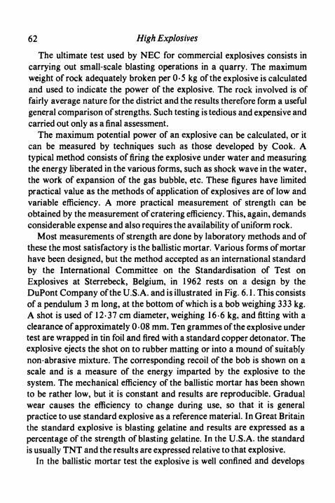
62 High Explosives
The ultimate test used by NEC for commercial explosives consists incarrying out small-scale blasting operations in a quarry. The maximumweight of rock adequately broken per 0-5 kg of the explosive is calculatedand used to indicate the power of the explosive. The rock involved is offairly average nature for the district and the results therefore form a usefulgeneral comparison of strengths. Such testing is tedious and expensive andcarried out only as a final assessment.
The maximum potential power of an explosive can be calculated, or itcan be measured by techniques such as those developed by Cook. Atypical method consists of firing the explosive under water and measuringthe energy liberated in the various forms, such as shock wave in the water,the work of expansion of the gas bubble, etc. These figures have limitedpractical value as the methods of application of explosives are of low andvariable efficiency. A more practical measurement of strength can beobtained by the measurement of cratering efficiency. This, again, demandsconsiderable expense and also requires the availability of uniform rock.
Most measurements of strength are done by laboratory methods and ofthese the most satisfactory is the ballistic mortar. Various forms of mortarhave been designed, but the method accepted as an international standardby the International Committee on the Standardisation of Test onExplosives at Sterrebeck, Belgium, in 1962 rests on a design by theDuPont Company of the U.S.A. and is illustrated in Fig. 6.1. This consistsof a pendulum 3 m long, at the bottom of which is a bob weighing 333 kg.A shot is used of 12-37 cm diameter, weighing 16-6 kg, and fitting with aclearance of approximately 0-08 mm. Ten grammes of the explosive undertest are wrapped in tin foil and fired with a standard copper detonator. Theexplosive ejects the shot on to rubber matting or into a mound of suitablynon-abrasive mixture. The corresponding recoil of the bob is shown on ascale and is a measure of the energy imparted by the explosive to thesystem. The mechanical efficiency of the ballistic mortar has been shownto be rather low, but it is constant and results are reproducible. Gradualwear causes the efficiency to change during use, so that it is generalpractice to use standard explosive as a reference material. In Great Britainthe standard explosive is blasting gelatine and results are expressed as apercentage of the strength of blasting gelatine. In the U.S.A. the standardis usually TNT and the results are expressed relative to that explosive.
In the ballistic mortar test the explosive is well confined and develops
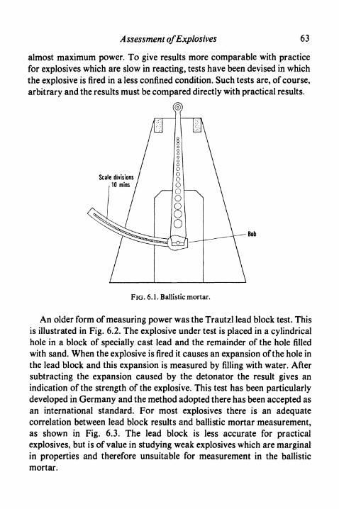
Assessment of Explosives 63
almost maximum power. To give results more comparable with practicefor explosives which are slow in reacting, tests have been devised in whichthe explosive is fired in a less confined condition. Such tests are, of course,arbitrary and the results must be compared directly with practical results.
FIG. 6.1. Ballistic mortar.
An older form of measuring power was the Trautzl lead block test. Thisis illustrated in Fig. 6.2. The explosive under test is placed in a cylindricalhole in a block of specially cast lead and the remainder of the hole filledwith sand. When the explosive is fired it causes an expansion of the hole inthe lead block and this expansion is measured by filling with water. Aftersubtracting the expansion caused by the detonator the result gives anindication of the strength of the explosive. This test has been particularlydeveloped in Germany and the method adopted there has been accepted asan international standard. For most explosives there is an adequatecorrelation between lead block results and ballistic mortar measurement,as shown in Fig. 6.3. The lead block is less accurate for practicalexplosives, but is of value in studying weak explosives which are marginalin properties and therefore unsuitable for measurement in the ballisticmortar.

64 High Explosives
Sand-
Explosive
v_Before firing
FIG. 6.2. Lead block test.
After firing
The ballistic mortar and lead block tests use only small amounts ofexplosive and are not applicable to slurry explosives which are tooinsensitive to detonate properly under such conditions. For theseexplosives it is useful to fire larger amounts of several kg under water andmeasure the period of oscillation of the gas bubble produced. The longerthe period the greater the energy of the gas bubble and this part of the totalenergy of the explosive has been found to correlate well with the blastingeffect of the explosive.
Velocity of Detonation
A particularly valuable method of measuring velocity of detonation isby high-speed camera, usually of a rotating mirror type. The layout isillustrated in Fig. 6.4. A slit is placed in front of the explosive, or of animage of the explosive in the optical system. This slit is in turnphotographed with the rotating mirror camera, the velocity of which isknown from stroboscopic measurements. As the detonation front isluminous, the illuminated point travels along the slit and gives aphotograph consisting of a line inclined to the axis of the camera at anangle which depends on the velocity of detonation and on the speed ofrotation of the mirror. By this method small charges can be studied and

Assessment of Explosives 65
constancy of velocity can be observed or any changes in velocitycalculated.
too
o 75
50
OWO
X ^X' X
XX/
JO 25 50 75
Lead block expansion, ml g"1
FIG. 6.3. Relationship between ballistic mortar and lead block tests.
Velocities can also be measured by electronic means and methods havebeen devised to give either continuous or intermittent readings. To obtain a
Elevation
Camera Slit Explosive
Plan
FIG. 6.4. Rotating mirror camera.

66 High Explosives
continuous record, a probe is placed along the cartridge, usually along thecentre. This probe consists of a conducting rod around which is wound ahelix of insulated wire. As the detonation wave passes along this wire, itbreaks the insulation and brings the wire into contact with the centralconductor. The resistance, therefore, diminishes as the detonation waveprogresses along the cartridge. By recording the resistance on anoscilloscope with a suitable time base, the rate of progress of thedetonation wave can be recorded.
As most explosives detonate at a constant speed, it is adequate in nearlyall cases to record the average velocity along a given length of theexplosive cartridge. To do this electronically two probes are inserted inthe cartridge at a known distance apart, the first being sufficiently far fromthe detonator for the explosion wave to have become stabilised. Theprobes, may, for example, consist simply of two pieces of insulated wirewound together. The detonation wave in passing causes contact bothmechanically and by its own ionisation. The two impulses received by apassage of current through the probes are caused to operate an electronictimer, which may in fact be calibrated directly to read the velocity ofdetonation of the explosive.
For routine use by unskilled personnel, the best method of measuringvelocities of detonation is one due to Dautriche. The principle is illustratedin Fig. 6.5. The two ends of a length of detonating fuse are inserted in theexplosive under test at a known distance apart. The mid point of the piece
Mark will appear hereMid point of fuse
Detonating fuse
Explosive
FIG. 6.5. Dautriche test.

A ssessment of Explosives 6 7
of detonating fuse is known and the part of the fuse near this point is placedover a V-shaped groove in a thin lead plate. When the explosive is fired thefuse commences to detonate first at the end nearer the detonator and laterat the other end. When the two detonation waves in the fuse meet theyreinforce and produce a distinct mark on the lead plate, visible particularlyas a split on the back. This point will be removed from the mid-point of thefuse by a distance which depends on the velocity of detonation of theexplosive under test according to the following equation:
D = ^/!/2/2
where D is the velocity of detonation of the explosive under test,dis the velocity of detonation of the detonating fuse,11 is the length of explosive under test,12 is the distance between the centre of the fuse and the mark on the
plate.Thus by measuring the distance of the mark on the lead plate from the midpoint of the fuse the velocity of detonation of the explosive under test maybe calculated. In practice, it is simple to construct a rule by which thevelocity can be measured directly from the lead plate.
Sensitiveness
The detonator sensitiveness of an explosive is measured by firing in itdetonators of increasing strength. It is convenient to stand the cartridge ofexplosive vertically on a lead plate with the detonator at the top. Theindentation produced on the lead plate then gives a good measure of thedetonation of the explosive. The weakest detonators for this test containonly mercury fulminate. Stronger detonators have base charges of PETN,increasing in amount as the strength of the detonator is increased (seep. 102).
An equally important and more severe requirement for commercialexplosives is that they should propagate in a train of cartridges. It must beremembered that in practice, when several cartridges are placed in aborehole it cannot be ensured that they are in contact and free from rock orcoal dust between them. It is, therefore, necessary for the explosive to beable to fire over a gap, whether this be air or other substance. The Ardeer

68 High Explosives
double cartridge test (ADC test) was the first routine test of this nature. Inthis test two cartridges, as used in practice, are rolled at a selected distanceapart in manilla paper. The assembly is placed on a flattened steel bar andfired from one end. The gaps are measured at which the second cartridge isdetonated and also fails to detonate. Differences of distance of 1 -25 cm atlower gaps and 2-5 or 5-0 cm at higher gaps are used. In the internationaltest for gap sensitiveness, the paper is omitted and the cartridges areattached to a wooden strap which is suspended above the ground. Forspecial purposes, such as with some modern weak coal mining explosives,a similar test can be carried out with the explosives enclosed in a cement orsimilar tube to simulate the confinement of a borehole. It is not normallynecessary to do tests with materials other than air between the cartridges.In America, however, a test has been developed in which the sensitivenessis measured by placing increasing thicknesses of card or similar materialbetween the cartridges.
Explosive
(a)
Explosive
FIG. 6.6. Friction tests, (a) Liquid explosives, (b) Solid explosives.

Assessment of Explosives 69
Whilst an explosive must have adequate sensitiveness to initiation bydetonators and to propagation of detonation through a train of cartridges,it must be sufficiently insensitive to friction and impact to be safe to handle.Sensitiveness to friction is commonly measured by some device as thatillustrated in Fig. 6.6. The explosive is smeared on the surface of a rotatingdisc on which rests a rod of similar or dissimilar material, carrying aknown weight. The speed of rotation can be varied and also the loademployed. The higher the speed and the greater the load before initiation ofthe explosive occurs, the lower the sensitiveness of the explosive. Some-times an oscillating plate is used instead of a rotating disc.
The sensitiveness of an explosive to impact is measured by determiningthe minimum height from which a given weight must be dropped in orderto initiate detonation. Many forms of "fall hammer" test have beendevised, the most important point of the various designs being the meansadopted for retaining the explosive. A simple and practical method, used atArdeer for many years, is shown in Fig. 6.7. In this the explosive is put
Hammer
\ i
Explosive
Rollerbearings
High tensilesteel
. 6.7. FaU hammer test.
between two roller bearings, themselves placed in a ring of hardened steeland resting on a hardened steel base. The falling weight is arranged to hitthe upper of the steel cylinders. The roller bearings must be changed aftereach ignition, as the condition of their surface markedly affects the resultsof the test. Similarly, the closeness of fit of the hardened steel ring is ofimportance. Typical weights employed are from 0-5 to 5 kg and heights offall may be up to 200 cm.

70 High Explosives
A common hazard in the handling of explosives is for them to besubjected to the effects of a blow which is to some extent at a glancingangle. This corresponds neither to pure impact, nor to pure friction. Acorresponding simple and useful test for the safety of an explosive duringhandling is the torpedo friction test illustrated in Fig. 6.8. In this, a torpedo
Head
FIG. 6,8. Torpedo friction test.
V-guide
Anvil
weighing 0-5 to 5 kg slides down an inclined plane to strike the explosiveresting on an anvil. The head of the torpedo and the material of the anvilcan be varied according to the materials of construction of an explosivesplant, or can be kept as mild steel in each case if an indication of relativehazards of explosives is to be obtained. The angle of fall is commonly 70 or80°.
Numerous tests for safety have been described in the past. It is probablyfar less important what test is employed than that some test should beundertaken before any explosive is handled on any but the smallest scale.All tests of the safety of explosives are in fact relative, so that the particulartest employed is a matter of convenience. As the presence of grit reduces
A ssessment of Explosives 71
the safety of explosives, tests are usually repeated after a quantity of finesand has been added.
Results of sensitiveness tests on typical explosives are given in Table6.1, for steel to steel surfaces, in the absence of grit.
TABLE 6.1 Sensitiveness of Explosives
Explosive
TNTRDX/TNTRDXPETNGeligniteAmmon geligniteNG powderTNT powder
Fall hammer(0-5 kg) (cm)
>20080-10025-3060-805-10
30-4020-30
160-200
Torpedo friction( lkg at 80°) (cm)
80-12040-^510-2035-4040-6040-60
>150100-120
Friction wheel(O- 5ms"1) (kg)
>50
104
30>50>50
Stability on Storage
All explosives are kept in magazines before use for periods which maybe up to several years. These magazines are normally buildings which haveneither special heating nor cooling, so that the temperature can varywidely in different parts of the world. Throughout this storage it isimportant that the explosive should remain safe and also retainsatisfactory properties.
Explosives are exothermic in decomposition and can be considered asbeing in a metastable condition. To determine whether instability can setin, it is necessary to subject the explosive to conditions which are moresevere than those occurring in practice. This in effect means that theexplosives must be subjected to a higher temperature than those normallyencountered. Unfortunately, as the temperature is increased the type ofdecomposition reaction changes, so that experiments at the highesttemperatures, although rapidly carried out, do not necessarily indicate thestability of the explosive under practical conditions. The ultimate test ofstability of an explosive must remain the maintenance of that explosive forseveral years at a temperature which somewhat exceeds the highest whichis to be expected in practice. Common temperatures range from 35° to5O0C. To obtain a quicker indication of the stability of an explosive, tests
72 High Explosives
are carried out at higher temperatures. Storage at 6O0C for several monthsgives useful information on the properties of an explosive, both chemicaland physical.
In determining stability by the above tests, it is usual to note the onset ofmass deterioration in the explosive. To obtain rapid results in the course ofhours or minutes, it is necessary to modify the tests so as to determine theinitial stages of decomposition. Many tests have been devised in which theexplosive is heated at a relatively high temperature and the extent of initialdecomposition determined by measuring the amount of gas evolved or theamount of acidity generated. Probably the best known of these tests is theAbel heat test in which a small amount of the explosive is heated (often at7O0C) and the time determined in which the gases liberated will produce astandard coloration on a starch-iodide paper. In Britain it is a legalrequirement that explosives and their explosive ingredients shall satisfythis test for times in the region of 10 min depending on the class ofexplosive. The heat test, like all similar tests, does not measure the truestability of an explosive, although an unstable explosive cannot give agood result. It can be markedly affected by minor impurities which have noeffect on the long-term life of the explosive, and the trend of the results withtime is frequently more important than the results themselves. Rapid testsare invaluable as a control of production in comparing one batch ofexplosive with another; their application to new explosives can, however,be very misleading.
For nitrocellulose, including guncotton, the most suitable stability test isthe B and J (Bergmann and Junk) test in which 2 g dried material is heatedfor 2 h at 1320C, the gases evolved being dissolved in water. The nitricacid in this water is reduced to nitric oxide, which is measured by volume.
For PETN and similar military explosives a valuable test is a vacuumstability test, in which some of the explosive is heated in vacuum and therate of evolution of gas measured.
Apart from maintaining chemical stability on storage, an explosivemust also maintain its physical form and its sensitiveness. Explosivescontaining nitroglycerine would, for example, be dangerous if they exudednitroglycerine during storage. To determine these properties there is noreal alternative to storing the explosive and examining it afterwards. Thelength of storage can, however, be reduced by marginally increasing thetemperature during the period.
Assessment of Explosives 73
Fume
The fume from an explosive is best determined by firing a round in a partof a mine which can be completely cut off from the circulating air. After theair and fume have been circulated by a fan for a sufficient period, samplesof the resulting mixture are taken and analysed.
Results of value can also be obtained by firing the explosive in a steelvessel reinforced with concrete. Care must be taken that by the use of leadtube or similar method the explosive is adequately confined, as unconfinedexplosives can produce abnormal fumes.
In measuring the nitrogen oxides produced by explosives, it must beremembered that ammonium nitrate can be left unreacted in smallamounts from explosives containing this substance. The method ofanalysis adopted should, therefore, be insensitive to ammonium nitrate, forexample the Griess-Ilosvay method. The composition of the gases willchange with time, as the oxidation of nitric oxide to nitrogen dioxide atthese low concentrations is extremely slow. A common procedure is todetermine nitrogen dioxide after a period sufficient to allow oxidation to becomplete. Carbon monoxide in the gases can be estimated by reaction withiodine pentoxide.
Whilst carbon monoxide and nitrogen oxides are the toxic products ofexplosives, other constituents of the fume cause a characteristic smell. Asthe nitroglycerine content of explosives is reduced, this smell tends tobecome rather unpleasant. Subjective tests must be used for its estimation.
Miscellaneous
Of other tests which are sometimes applied to high explosives, mentionshould be made of the tests for brisance. Brisance is an ill-defined word,best described by saying that an explosive of high brisance, when firedunconfined on a steel plate, will bend or shatter that plate more effectivelythan an explosive of low brisance. The Hess and Kast tests for brisancedepend on this property, using the deformation of a metal cylinder by theexplosive as a measure of the property. In most countries these tests arenow little used.
A qualitative test of some value is to fire the explosive standing on itsend on a plate of lead about 2-5 cm thick. A strong high velocity explosive
74 High Explosives
will punch a hole completely through the plate, whereas a weak lowvelocity explosive will cause merely a minor indentation. This sort of testgives a good empirical indication of the completeness of detonation of theexplosive in the unconfined state, provided that it is used along withmeasurements of power and velocity.
Particular tests are used for nitrocellulose for use in blasting explosives.A typical test is the clearing test, which consists essentially of mixingblasting gelatine under controlled conditions and determining the time atwhich the explosive is lifted by the stirrers from the bottom of the mixingvessel. This test measures the speed of gelatinisation of the nitrocellulose.
References
COOK , M. A., The Science of High Explosives. Reinhold, New York, 1958.Me ADAM , R. and WESTWATER , R., Mining Explosives. Oliver & Boyd, London, 1958.MARSHALL , A., Explosives. Churchill, London, 2nd ed. 1917.
CHAPTER 7
Permitted Explosives
IN MANY coal mines there is a continual evolution of methane (firedamp)into the air of the workings. The methane is trapped in the coal or rock,often in pockets within the veins, and is sometimes at relatively highpressure. It is usually of fairly high purity, containing only minor amountsof other hydrocarbons and nitrogen. Methane, when mixed with air inproportions between 5 and 14%, forms an explosive mixture. In gassymines, therefore, there is always the danger that a mixture may be formedwhich, if ignited, can cause serious damage and loss of life.
In coal mines, also, there is a further danger in that the working of thecoal produces coal dust. Coal dust when mixed with air gives a mixturewhich when suitably ignited can undergo a dust explosion. Indeed, if anexplosion of firedamp (or coal dust) occurs, the wave produced can stir thedust lying in the mine into the air, producing a mixture which can lead tofurther propagation and devastating explosion. In the history of coalmining there have been many examples of both firedamp and coal dustexplosions, and the latter in particular have led to serious loss of life.
The firing of explosives in a gassy mine must always be undertaken withsuitable consideration of safety. The same is, of course, true of all work, asany electrical fault, or spark from some metals and rock, can give rise toinitiation of explosion should firedamp be present in suitable amounts.Most ignitions which occur are local and limited in extent, but there isalways the possibility of their spreading to major proportions. The mainmethod of combating this risk is to ensure suitable ventilation so that thefiredamp liberated is carried away at a concentration below that at whichexplosion can occur. Frequent testing of atmospheres, particularly atpoints where ventilation is less effective than usual, is essential. Stonedusting is used to prevent coal dust explosions. A further and important
75

76 High Explosives
measure of safety is the provision of explosives which do not ignitemethane/air mixtures under the condition of use. In Great Britain, anexplosive for use in gassy mines must pass certain tests carried out by theSafety in Mines Research Establishment at Buxton, as a result of which theMinistry of Power issues the necessary authorisation for use and placesthe explosive on the Permitted List. Arrangements similar in principle aremade in nearly all countries. In Britain the safety achieved is such thatignitions associated with explosives are less than 1 per 10 million shotsfired, and are only about a quarter of the total ignitions in coal mines.
Initiation of Firedampand Coal Dust Explosions
The high temperature reached in a detonation wave makes it seemimprobable that explosives can be designed which do not cause ignition ofan explosive mixture of methane and air. The possibility of doing sodepends on the very short time for which the mixture is subjected to thesetemperatures. Methane/air mixtures have a finite induction period andunless energy is applied for at least a considerable proportion of thatperiod, explosion will not result. Deflagrating explosives, such as black-powder, are more dangerous in coal mining conditions than highexplosives, because of the much greater time which they take in burning.The strongest high explosives also readily ignite methane/air mixtures,because of their extremely high reaction temperatures. Weaker explosives,but having high speeds of reaction, are relatively safer. Present-daypermitted explosives, therefore, always consist of high explosives of whichthe reaction temperature has been adjusted to a suitably low figure. At thesame time care is taken to avoid constituents in the explosive which cancontinue to burn after the main reaction has been completed, thus settingup in the methane/air mixture a continuing source of ignition.
The mechanisms by which explosives can cause ignition of methane/airmixtures are the following:
1. By direct action of the shock or expansion wave from the explosive.2. By indirect action of the shock wave after it has been reflected from
solid surfaces in the vicinity of the explosion.3. By ignition of the methane/air mixture on mixing with the hot
gaseous products of the explosion.

Permitted Explosives 77
4. By hot reacting particles of explosive escaping into the methane/airmixture.
It is probable that all of the above mechanisms can operate with certainexplosives under some conditions. Strong high velocity explosivessuspended in methane/air mixtures cause ignition by the effect of theirshock wave. With some high energy explosives, calculations show that thehot gaseous products, when mixed with suitable proportions ofmethane/air mixtures, can give temperatures and concentrations whichlead to gas explosion. Recent studies indicate that explosives can causecentres of initiation of methane/air mixtures at a distance from theexploding charge, and the fact that in many tests the probability ofinitiation varies according to the shape and size of the containing vesselsuggests that shock wave reflections can play an important part. Finally,many workers have shown that reacting particles can penetrate beyondthe expanding reaction products of the explosive into the methane/airmixture and can at least assist in causing initiation.
In the practical case, explosives designed for use in coal mines are suchthat they are unlikely to initiate methane/air explosions by their shockwaves when fired inside boreholes. The addition of cooling salts reducesthe temperature of the explosion below that at which the gaseous productscan cause initiation by thermal effects alone. Therefore only mechanisms(4) and (2) are likely to be of practical importance. Experience shows thatinitiation by reacting particles of explosive, whilst always possible, isunlikely to be dominant. It is found rather that, in most practicalconditions, there is a good correlation between the power developed by theexplosive under the actual conditions of firing and the likelihood ofinitiation of methane/air mixtures. The chance of an explosion thereforedepends not only on the explosive, but also on the geometry of theconditions of use, and the safety of a coal mining explosive depends on theoperations in the mine for which it is employed.
Research throughout the world has rightly been aimed for many yearsat the production of explosives incapable of initiating firedamp explosionsunder any practical conditions. The attainment of such an ideal dependson reducing the effective power of the explosive, so that there are nogeometrical arrangements in the coal mine which can cause that explosiveto ignite the gas mixture. Such low power unfortunately can only beachieved by limiting the proportion of nitroglycerine and other reactive
78 High Explosives
ingredients of the explosive to the minimum possible values. As a result theexplosives inevitably become less sensitive and less certain in their use.There is an increasing danger that when a number of cartridges are fired ina borehole, particularly when they can be affected by rock movements,some of the cartridges will fail to detonate. These undetonated cartridgescan also be liable to deflagrate, that is commence to burn when in theborehole and continue to decompose when the coal or rock is displaced.Such an effect introduces a danger into the coal mine of a different, but stillserious, nature. Even if by suitable design of explosive deflagration beavoided, the presence of undetonated cartridges in the product is mostundesirable.
It will, therefore, be seen that the best and safest practice is to use in eachsituation in the coal mine an explosive which is best adapted for theoperation in hand. The use of unnecessarily weak explosives, even thoughapparently safer in some tests, is often a disadvantage and can bedangerous. These considerations have led to the development of a series oftypes of explosives suited for particular purposes in coal mines andsubjected to tests relevant to their individual uses. Thus, in Britain thereare now five classes of permitted explosives. In Germany there are threeclasses. In the U.S.A. geological conditions are different and the hazardsare less than in Europe, and it has been possible to work throughout withthe strongest types of permissible explosives.
Gallery Testing of Permitted Explosives
It was early recognised that an explosive is more hazardous in a coalmine if it is fired in a borehole from which the stemming is omitted orblown out early by the explosive than if it is fired in a properly stemmedhole and does adequate work in bringing down rock or coal. The testswhich led to the original permitted explosives, now called Pl explosives,were therefore designed to test the product under these conditions.
The testing gallery consists of a steel cylinder, 1 -5 m in diameter. Thefirst 5-5 m is sealed by a paper or polythene diaphragm and the remaining9-8 m is left open to the atmosphere. The general arrangmement is shownin Fig. 7.1. At the end opposite the diaphragm there is a hole about 30 cmin diameter against which a heavy cannon is placed. The joint is sealed by

Permitted Explosives 79
Gas explosiM / Open endchamber Oiaphraam
FIG. 7.1. Testing gallery for permitted explosives.
a rubber ring. The cannon is 1 -5 m long and has in it a borehole 5-5 cm indiameter and 1 -2 m long. The explosive is placed in this borehole with orwithout stemming according to the test being carried out. After the cannonhas been placed in position, methane is introduced into the enclosedportion of the gallery and thoroughly mixed with the air. The explosive isthen fired and the ignition, or otherwise, of the methane/air mixtureobserved from a safe distance.
The results obtained in gallery testing depend appreciably on whetherthe explosive is stemmed or not and also on the method of initiation. In theBritish test the stemming used is a close-fitting plug of clay 2-5 cm long. Inspite of its short length in comparison with practical stemming, it has amarked effect on the likelihood of ignition of the gas mixture in the gallery.In the original tests, the detonator was inserted last into the cannon andthis method of initiation is called direct initiation. If the detonator is at theopposite end of the train of cartridges, and is inserted first into the cannon,the initiation is called inverse or indirect and the probability if ignition ofthe methane/air mixture is appreciably increased. Figures illustrating thiseffect have been given by Taylor and Gay and are shown in Fig. 7.2. Thesame authors have given figures showing how the severity of the testincreases as the diameter of the gallery is decreased.
In other countries galleries of similar construction are used, but thedimensions are frequently somewhat different. Data are given in Table 7.1.
Gallery testing in the equipment above is employed for studying thesafety of explosives for general applications in coal mines. For explosivesfor particular purposes special tests have been devised, often to simulate tosome extent the hazards which may occur in practice. Typical of thesetests are the break tests devised in Britain. These tests are for studyingexplosives intended for use in ripping, that is in increasing the height ofroadways in mines after the coal has been extracted. The extraction of the

80 High Explosives
coal relieves stresses in the surrounding rocks and is therefore liable tocause breaks which can contain methane/air mixtures. Three tests weredevised to indicate the hazard involved in shotfiring in thesecircumstances.
TABLE 7.1 Galleries for Testing Coal Mining Explosives
Country
BritainU.S.A.Germany (Dortmund)BelgiumFrancePolandU.S.S.R.
Gallery
Diam.(m)
1.51.91.8xl.35b1.6221.65
Length*(m)
5.56.1553.53.35
Cannon
Bore diam.(mm)
55575555305055
Bore length(cm)
1205560506070 or 12090
a Explosion chamber only.b Elliptical section.
840
E- 560
o£1CJ
280
Direct initiation— Inverse initiation
IO 20 40 60
Power, % blasting gelatine
Ro. 7.2. Effect of initiation on gallery testing.
80
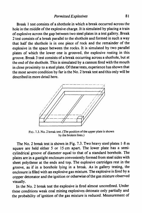
Permitted Explosives 81
Break 1 test consists of a shothole in which a break occurred across thehole in the middle of the explosive charge. It is simulated by placing a trainof explosive across the gap between two steel plates in a test gallery. Break2 test consists of a break parallel to the shothole and formed in such a waythat half the shothole is in one piece of rock and the remainder of theexplosive in the space between the rocks. It is simulated by two parallelplates of which the lower one is grooved, the explosive resting in thisgroove. Break 3 test consists of a break occurring across a shothole, but atthe end of the shothole. This is simulated by a cannon fired with the mouthin close proximity to a steel plate. Of these tests, experience has shown thatthe most severe condition by far is the No. 2 break test and this only will bedescribed in more detail here.
FIG. 7.3. No. 2 break test. (The position of the upper plate is shownby the broken lines.)
The No. 2 break test is shown in Fig. 7.3. Two heavy steel plates 1 -8 msquare are held either 5 or 15 cm apart. The lower plate has a semi-cylindrical groove of diameter equal to that of a standard borehole. Theplates are in a gastight enclosure conveniently formed from steel sides withsheet polythene at the ends and top. The explosive cartridges rest in thegroove, as if in a borehole lying in a break. As in gallery testing, theenclosure is filled with an explosive gas mixture. The explosive is fired by acopper detonator and the ignition or otherwise of the gas mixture observedvisually.
In the No. 2 break test the explosive is fired almost unconfined. Underthese conditions weak coal mining explosives detonate only partially andthe probability of ignition of the gas mixture is reduced. Measurement of
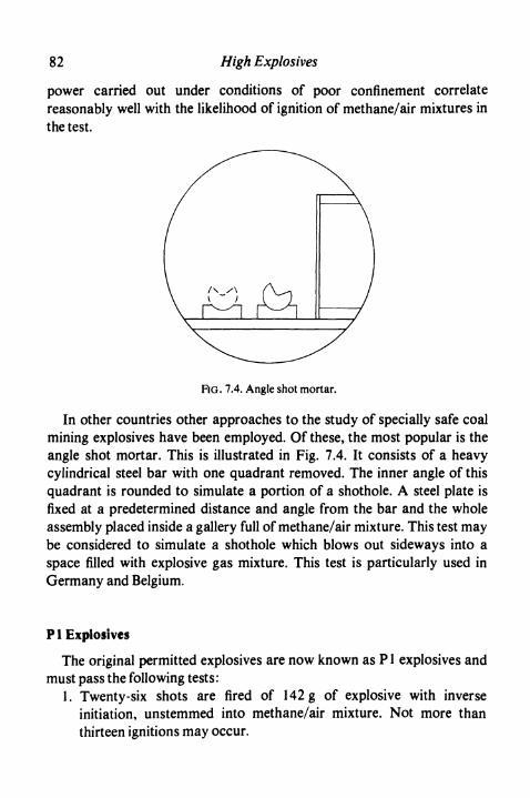
82 High Explosives
power carried out under conditions of poor confinement correlatereasonably well with the likelihood of ignition of methane/air mixtures inthe test.
RG. 7.4. Angle shot mortar.
In other countries other approaches to the study of specially safe coalmining explosives have been employed. Of these, the most popular is theangle shot mortar. This is illustrated in Fig. 7.4. It consists of a heavycylindrical steel bar with one quadrant removed. The inner angle of thisquadrant is rounded to simulate a portion of a shothole. A steel plate isfixed at a predetermined distance and angle from the bar and the wholeassembly placed inside a gallery full of methane/air mixture. This test maybe considered to simulate a shothole which blows out sideways into aspace filled with explosive gas mixture. This test is particularly used inGermany and Belgium.
P !Explosives
The original permitted explosives are now known as Pl explosives andmust pass the following tests:
1. Twenty-six shots are fired of 142 g of explosive with inverseinitiation, unstemmed into methane/air mixture. Not more thanthirteen ignitions may occur.

Permitted Explosives 83
2. Five shots are fired of 795 g explosive with direct initiation, stemmedinto methane/air mixture. No ignitions may occur.
3. Five shots are fired of 795 g explosive with direct initiation, stemmedinto coal dust/air mixture. No ignitions may occur.
In designing P1 explosives, the major consideration is the power. Themaximum power of an explosive likely to pass the test depends on the bulkdensity and Table 7.2 gives approximate figures. Powers exceeding thosequoted are liable to cause ignitions in the unstemmed test.
TABLE 7.2 Maximum Strengths of Pl Explosives
Type
GelatineSemi-gelatinePowder
Density
1-51-251-0
Max. strength % blasting gelatine
586266
Ignitions when firing into coal dust suspension are relatively uncommonand appear to depend on the inclusion in the explosive of certain types ofingredients. This effect is, for example, often observed with explosivescontaining sodium nitrate. For this reason this ingredient is usuallyavoided and the oxidising agent preferred is ammonium nitrate. To reducethe power to a suitable level, the usual additive is sodium chloride in finelydivided form. Typical compositions are quoted in Table 7.3 for Polar Ajaxand Polar Viking, gelatine and powder explosives respectively.
P2 Explosives
Lemaire, in Belgium, introduced the concept of enclosing explosives inan inert sheath of cooling material. Most commonly sodium bicarbonatehas been used for this purpose. Originally it was packed as a powder roundthe explosive cartridge and inside an outer paper shell. A further methodused in Great Britain was to prepare a "felt" consisting of sodiumbicarbonate with a small amount of woodpulp to bind it in usable form;this bicarbonate felt was wrapped round the cartridge of explosive. Morerecently in Belgium the sheath has been produced as compressed hollowcylinders of sodium bicarbonate into which the explosive is placed.
Sheathed explosives appeared very successful at their introduction, but

84 High Explosives
TABLE 7.3 Compositions of Permitted Explosives0
P1 Explosives
Explosive
Gelatine(Polar Ajax)
Powder(Polar Viking)
Pulsed Infusion(Hydrobel)
NG
26-5
10-5
40
NC
0-8
—
2
AN
42-7
70-7
20
Salt
24-6
10
27
Barytes
—
—
9-5
Combustible
3-8
8-8
1
Other
1-6
—
0-5
P3 Explosives
Explosive
Gelatine(Unigel)
Semi-gelatine(Unigex)
Powder(Unipruf)
NG
29-2
16
8
NC
0-8
0-4
—
AN
25
46-5
53
Salt
42-5
25-5
29
Combustible
2
3-5
9-5
Other
0-5
8-1
0-5
P4 Explosives
Explosive
Powder(Carrifrax)
NG
9
AN
10
Amm.chloride
28
Sod.nitrate
46-5
Combustible
6
Other
0-5
a For each composition, official permitted limits are in fact ascribed for each ingredient.The compositions quoted are the mid points of these limits, adjusted to total 100%.
later experience was rather disappointing. There is always the danger ofbreakage of the sheath and therefore loss of safety. In Britain they havebeen almost entirely superseded by P3 explosives described below. Thetests required for P2 explosives are similar to those for the P3 variety.

Permitted Explosives 85
P 3 Explosives
These explosives, when introduced into Britain, were called "equivalentto sheathed" or Eq.S. explosives. Currently, the explosives must pass thefollowing tests:
1. Twenty-six shots are fired, consisting of 397 g with inverse initiation,unstemmed into methane/air mixture. Not more than thirteenignitions may occur.
2. Five shots are fired consisting of 102Og with direct initiation,stemmed into methane/air. No ignitions may occur.
3. Five shots are fired consisting of 567 g with inverse initiation,unstemmed into coal dust/air mixture. No ignitions may occur.
In the design of P3 explosives the first consideration is again that ofpower. Approximate limits, above which ignition of gas is likely to occur inunstemmed tests, are given in Table 7.4.
TABLE 7.4 Maximum Strengths ofP3 Explosives
Type
Gelatine
Semi-gelatine
Powder
Density
1-65
1-3
1-0
Max. strength % blasting gelatine
42
47
50
When explosives of the power shown in this table are prepared, thepower per unit length of the explosive cartridge is similar to that of thepower of a sheathed explosive made from a Pl composition. Effectively,therefore, the difference between a P2 and a P3 explosive is that the inertmaterial in the sheath of the former is distributed uniformly through theexplosive composition of the latter. For reasons of stability, however,sodium bicarbonate is no longer used; instead an increase in theproportion of sodium chloride gives the required cooling effect.
In this way P3 explosives of powder or semi-gelatine type can bedirectly designed. The addition, however, of sodium chloride to a gelatineexplosive, in the proportions required, is not possible without loss of thegelatine consistency. In designing a P3 gelatine explosive, therefore, theextra cooling salt is substituted mainly for the oxygen-balanced mixture of

86 High Explosives
ammonium nitrate and combustible. The development of P3 explosiveshas been described by Taylor and Gay and typical compositions are givenin Table 7.3.
P4 Explosives
P4 explosives were specifically designed for the operation of rippingwith delay detonators (see p. 143) and must satisfy the following tests:
1. Twenty-six shots are fired consisting of 397 g inversely initiated,unstemmed into methane/air mixtures. Not more than threeignitions may occur.
2. Five shots are fired of the maximum permitted charge weight ofexplosive into methane/air mixture in Break test I. No ignitionsmay occur.
3. Break Test II uses a gas mixture of 3-60% propane with air andnitrogen, which is more easily ignited than methane/air.Preliminary shots determine the most hazardous charge ofexplosive not exceeding 227 g. Twenty-six shots are then fired atthis weight and not more than thirteen ignitions may occur.
4. Five shots of 30-5 cm length and 3-7 cm diameter are fired inmethane/air in Break Test III. No ignitions may occur.
In designing P4 explosives, it must be remembered that the overallstrength is limited by the requirement of the gallery test, which is evenmore severe than that employed for P3 explosives. It is, therefore,necessary to include even greater proportions of cooling salts into theexplosive than is the case with the P3 class.
Equally severe in practice is the requirement of the break 2 test. To passthis test the explosive must have a low power when fired in an unconfinedcondition. The actual power has not been quantitatively measured, but isprobably in the region of 15% blasting gelatine. To achieve such a result, itis necessary deliberately to design the explosive in such a way that onlypartial reaction occurs in the unstemmed condition. Such partial reactioncan be achieved by either of two ways.
The first method, popular in Britain, consists of adjusting the nature ofthe ingredients and particularly their specific surface in such a way that thereaction of the oxidiser and combustible is slow. The ingredients are also
Permitted Explosives 8 7
such that a flame-quenching solid is released in a form having a highspecific surface. For example, in the first explosive of this class, N.E. 1235,much of the ammonium nitrate was introduced in the form of an intimategranular mixture containing calcium carbonate.
In the other method, particularly popular in Germany, the ammoniumnitrate is replaced by an equimolar mixture of ammonium chloride andpotassium or sodium nitrate. The reaction between the salts, which givespotassium or sodium chloride and ammonium nitrate or its decompositionproducts, is relatively slow and does not occur to a marked extent when theexplosive is fired in an unconfined condition. This method of working isparticularly effective in reducing the power of an explosive in theunconfined condition. Used alone it has not proved popular in Britain,because of the low power which tends to be developed under practicalfiring conditions. Moreover, the finely divided sodium chloride smokewhich is produced by the explosive tends to be unpleasant for the miners.
The most recent practice in Britain is to employ a combination of theabove methods so as to give the required overall effect on the power of anexplosive in an unconfined condition. Compositions and properties of suchan explosive are given in Table 7.3.
P5 Explosives
P5 explosives were specifically designed for blasting solid coal withmillisecond delay detonators. The nature of this application and itsadvantages are described in Chapter 14 (see p. 144). In Europe, exchangedion explosives are used for this purpose. Originally, they gave undetonatedcartridges liable to deflagration, but this problem has been overcome byenclosing the cartridges in a plastic sheath and redesigning the explosive tobe more powerful. In Britain a consideration of the basic requirements ofthe explosive has led to an approach in a different direction. It is consideredthat three special hazards to be overcome relate to ignition of firedamp,desensitisation of the explosive and deflagration.
The particular hazard of firedamp ignition relates to the circumstancewhen a hole fired early in the round breaks the coal at another hole andexposes the explosive before it detonates. This is simulated by firing gallerytests similar to those described above, but with inverse initiation of a
88 High Explosives
column of cartridges which reach to 5 cm from the mouth of the cannon.Twenty shots of 567 g explosive are fired into methane/air mixture and noignitions may occur. The explosive must in addition pass the second andthird tests applied to P3 explosives.
Another hazard is that cartridges fired early will cause compression inother holes and thus desensitise the explosive. To overcome this a sensitiveexplosive is required and one of semi-gelatine type is used in Britain.
Deflagration, or smouldering, is more likely to occur with this techniqueof off-the-solid blasting than in other methods. This is because coal dustmakes deflagration more likely and more dangerous; because there is thetendency noted above towards desensitisation; and because of the highpressures which can be developed in boreholes in view of the goodstemming made necessary because blasting is not towards a free face (seep. 138). Deflagration is tested by enclosing two cartridges in a steel tubewith controlled venting and with a 10 cm gap between the cartridges filledwith coal dust. When one cartridge is detonated the other should notdeflagrate if the venting is more than minimal. The nature of the fuel usedhas a major influence on the liability to deflagration: salts of organic acidsare often used. The first P5 explosive (Dynagex) used a special combinedfuel and coolant.
P4/5 Explosives
The requirement to use both P4 and P5 explosives in a single mineworking leads not only to inconvenience in supply but also to a potentialhazard should either explosive be used for the wrong purpose. This has ledto the development of P4/5 explosives which pass the tests for both P4 andP5 types and which can therefore be used either for ripping or for firing offthe solid with delays.
These are essentially P4 explosives which incorporate the fuelsdeveloped for P5 types to avoid the danger of deflagration. When fired offthe solid the confinement is sufficient to ensure that the explosive developsits full power and can perform the required work.
Other Coal Mining Explosives
The first successful method of firing explosives in solid coal was the

Permitted Explosives 89
pulsed infusion technique (see p. 143). This requires explosive which willfire under a pressure of water of 1-4 MPa and which also passes suitablepermitted tests, either Pl or P3. Such explosives are based on the additionof high density materials, such as barium sulphate, to a gelatinecomposition, so as to ensure that it will detonate at high velocity. Whenthis is done propagation under high water pressure can be achieved. Byadding appropriate quantities of cooling salts, either Pl or P3 explosivescan be designed. The former propagate better under pulsed infusionconditions, whereas the latter enable the shotfirer to use the same explosivefor further operations at the coal face. With the introduction of P5explosives, pulsed infusion techniques are likely to diminish in importance,but they have the advantage of reducing airborne dust and are thereforeparticularly valuable in anthracite mines.
Mention should be made of devices which are not, strictly speaking,explosives, but which have an explosive effect and can be used for similarpurposes in coal mining. Such devices are Airdox, Cardox and Hydrox.All consist of strong metal tubes containing at one end a bursting disc ordevice of known venting strength. Inside the tube is a cartridge which iscaused to liberate high pressure gas at low temperature. When the pressurereaches the designed value the bursting disc breaks and the gas is liberatedviolently from nozzles at the end of the tube. This sudden liberation of gascauses breaking of the coal. Because of their inconvenience and otherdisadvantages in operation, these devices are now of limited importance.
References
TAYLOR, J., and GAY, P. F., British Coal Mining Explosives. Newnes, London, 1958.Thorpe's Dictionary of Applied Chemistry, 4, 558. Longmans Green, London, 4th ed.
1940.
For details of permitted tests, reference should be made to the Health and SafetyExecutive. For uniformity in text, figures chosen for the above account have beenconverted to their nearest equivalents in SI units.


Part II. Blasting Accessories


Introduction
IN EARLY attempts to use nitroglycerine for blasting purposes, the practicewas to ignite the nitroglycerine with blackpowder charges. Whilst thiscaused combustion, it was soon found to be unreliable in producingdetonation. Satisfactory results were first achieved by Nobel by the designof the detonator, which employed fulminating substances as ignitioncompounds. These materials, of a type now called initiating explosives, arecharacterised by the fact that even in small quantities they detonate onapplication of flame. Although initiating explosives are sensitive, not onlyto flame, but also to friction and percussion, they need be made only insuch small quantities that special precautions in their handling can betaken. In the course of manufacture, the initiating explosives are enclosedin metal tubes and thereby so protected that the finished product can behandled without danger.
It is always necessary for the shotfirer to be at a distance from theexplosive when it is detonated. This can be achieved in either of two ways.The earlier method was to use safety fuse which was ignited at one end andburned slowly towards the detonator, thus giving the shotfirer time toretire to safety. The development of satisfactory and reliable safety fusewas of considerable importance to the explosives industry. But if a largenumber of shots had to be fired, the operator might not have time to ignitethe many ends of safety fuse and still retire to protection before the firstexplosive detonated. Therefore, a method was sought by which a numberof lengths of safety fuse could be ignited by a single operation. This led tothe development of igniter cord, which can be joined to the ends of thelengths of safety fuse by special connectors. The shotfirer then only has toignite one end of igniter cord before retiring.
Although safety fuse is reliable and relatively constant in burning speed,a number of shots fired with this aid will naturally detonate at slightlydifferent times. This can be an advantage, particularly if the times ofdetonation are varied by altering the length of safety fuse, or by ensuring
93
94 High Explosives
suitable delays by the use of igniter cord. On other occasions, however, it isdesirable to be able to fire a number of shots simultaneously. For thispurpose detonating fuse can be employed by which ignition is caused by adetonation wave instead of burning. A detonation wave in the fuse travelsat 6500 m s"1 so that a larger number of shots can be fired almostsimultaneously. The detonating fuse itself must be initiated by a detonator,but can be used without further attachments for initiating mostnitroglycerine explosives. For less sensitive explosives such as slurries thedetonating fuse can be used to initiate a primer or booster of a castexplosive such as pentolite.
The alternative method of ensuring safety for the shotfirer is to enablehim to fire the round of shots from a safe distance by using electricalmeans. For this purpose electric detonators have been developed. Anelectric detonator is placed in each shothole, the leads are connected into asingle electrical circuit and the whole fired from a central point. Theoriginal electric detonators did not allow use to be made of the advantagesdescribed in Chapter 14, of firing shotholes in a prearranged order in time.This led to the development of delay detonators, which are electricdetonators incorporating delay elements. When an electric current ispassed through delay detonators they are actuated immediately, but thebase charges do not detonate till after prearranged times. The first delaydetonators manufactured had intervals of either 1 or 0-5 s, but morerecently delays of the order of 30 to 50 ms have been produced and are inwide use.
The above represent accessories which do not directly perform blastingoperations, but which are essential for the efficient and safe use of blastingexplosives. For the explosives industry and for the user they are asimportant as the blasting explosives themselves.

CHAPTERS
Initiating Explosives
Mercury Fulminate
Mercury fulminate has the formula Hg(ONC)2. It was probablydiscovered by Howard in 1800 and its constitution was established by Nef.The method of preparation is known as the Chandelon process and is acomplex reaction studied by Wieland. Mercury is dissolved in an excess ofwarm nitric acid and ethyl alcohol added to the resulting solution.Considerable bubbling occurs in the strong reaction, so this is usuallycarried out in capacious glass "balloons". At the end of the reaction themercury fulminate remains as a dense precipitate which is filtered andwashed several times.
Mercury fulminate is a pale brownish solid, insoluble in cold water, butdissolving slightly in hot water to a solution which does not give the normalmercury reactions. In cold conditions it is stable, but at highertemperatures gradually decomposes and loses strength as an explosive. Ithas a density of 4-45 g ml"1 and a velocity of detonation, when compressedto a practical density of 2-5, of about 3600 m s"1.
When used in detonators, mercury fulminate is frequently mixed with10 or 20% of potassium chlorate. Such mixtures have a better oxygenbalance and therefore give improved and more reliable initiation of otherexplosives.
LeadAzide
Lead azide, discovered by Curtius in 1891, has the formula Pb(N3)2.Hydrazoic acid, HN3, is a liquid boiling at 370C and because of itssensitiveness is an extremely dangerous substance. As a strong acid it
95
96 High Explosives
gives salts with many metals and these can range from stable compoundssuch as sodium azide to very sensitive solids such as the copper and silverazides. The starting point in azide manufacture is sodium azide, itself madefrom sodamide and nitrous oxide. Sodium azide is one of the few solubleazides and therefore the salts of other metals can readily be prepared byprecipitation in aqueous solution.
Lead azide is manufactured by reaction of sodium azide with either leadnitrate or lead acetate. It is a white crystalline solid, insoluble in cold waterand stable on storage. It is very sensitive to friction and impact and has avelocity of detonation, when pressed to a density of 3 -8, of 4500 m s"1.
Two crystallographic forms of lead azide are important, the ordinaryalpha form which is orthorhombic and the beta form which is monoclinic.The densities of these forms are 4-71 and 4-93 respectively. It was formany years believed that the beta form is the more sensitive to friction andimpact and accounted for detonations which have occurred in themanufacture and handling of the substance. It is now known that the betaform is in fact no more sensitive than the alpha. Even the alpha form, whenpresent as large crystals, is very sensitive and conditions can arise(particularly when the formation of the lead azide is controlled by diffusioneffects) where spontaneous detonation occurs. Although with modernknowledge these hazards can be avoided, pure lead azide is nevertheless adangerous compound and is now made only for military purposes.
Commercially, lead azide is usually manufactured by precipitation inthe presence of dextrine, which considerably modifies the crystallinenature of the product. The procedure adopted is to add a solution ofdextrine to the reaction vessel, often with a proportion of the lead nitrate orlead acetate required in the reaction. The bulk solutions of lead nitrate andof sodium azide are, for safety reasons, usually in vessels on the oppositesides of a blast barrier. They are run into the reaction vessel at a controlledrate, the whole process being conducted remotely under conditions ofsafety for the operator. When precipitation is complete, the stirring isstopped and the precipitate allowed to settle; the mother liquor is thendecanted. The precipitate is washed several times with water until pure.The product contains about 95% lead azide and consists of roundedgranules composed of small lead azide crystals; it is as safe as mostinitiating explosives and can readily be handled with due care.
Lead azide has virtually supplanted mercury fulminate in the
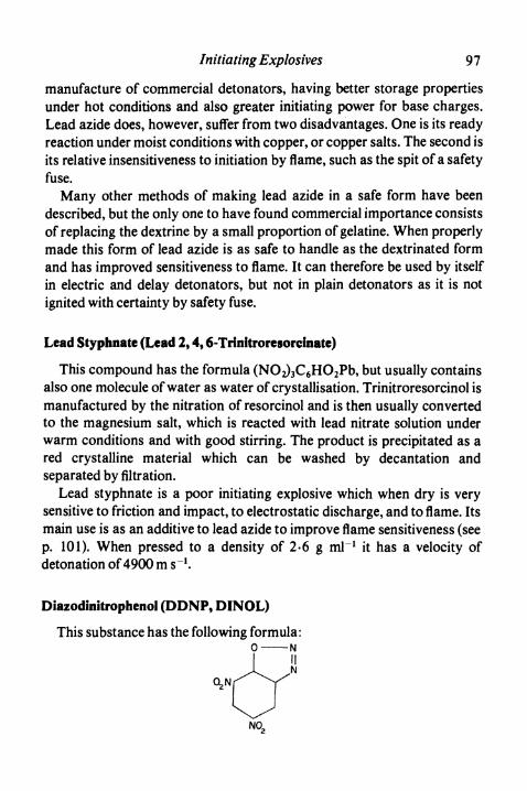
Initiating Explosives 9 7
manufacture of commercial detonators, having better storage propertiesunder hot conditions and also greater initiating power for base charges.Lead azide does, however, suffer from two disadvantages. One is its readyreaction under moist conditions with copper, or copper salts. The second isits relative insensitiveness to initiation by flame, such as the spit of a safetyfuse.
Many other methods of making lead azide in a safe form have beendescribed, but the only one to have found commercial importance consistsof replacing the dextrine by a small proportion of gelatine. When properlymade this form of lead azide is as safe to handle as the dextrinated formand has improved sensitiveness to flame. It can therefore be used by itselfin electric and delay detonators, but not in plain detonators as it is notignited with certainty by safety fuse.
Lead Styphnate (Lead 2,4,6-Trinitroresorcinate)
This compound has the formula (NO2)SC6HO2Pb, but usually containsalso one molecule of water as water of crystallisation. Trinitroresorcinol ismanufactured by the nitration of resorcinol and is then usually convertedto the magnesium salt, which is reacted with lead nitrate solution underwarm conditions and with good stirring. The product is precipitated as ared crystalline material which can be washed by decantation andseparated by filtration.
Lead styphnate is a poor initiating explosive which when dry is verysensitive to friction and impact, to electrostatic discharge, and to flame. Itsmain use is as an additive to lead azide to improve flame sensitiveness (seep. 101). When pressed to a density of 2-6 g ml"1 it has a velocity ofdetonation of 4900 m s"1.
Diazodinitrophenol (DDNP9 DINOL)
This substance has the following formula:O N
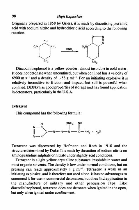
98 High Explosives
Originally prepared in 1858 by Griess, it is made by diazotising picramicacid with sodium nitrite and hydrochloric acid according to the followingreaction:
HNO2
Diazodinitrophenol is a yellow powder, almost insoluble in cold water.It does not detonate when unconfined, but when confined has a velocity of6900 m s"1 and a density of 1-58 g ml"1. For an initiating explosive it isrelatively insensitive to friction and impact, but still is powerful whenconfined. DDNP has good properties of storage and has found applicationin detonators, particularly in the U.S.A.
Tetrazene
This compound has the following formula:
e 0NH3 NHN - OL I I
I! C - N = N - N - C — NH2 • H2O/
N - N'
Tetrazene was discovered by Hofmann and Roth in 1910 and thestructure determined by Duke. It is made by the action of sodium nitrite onaminoguanidine sulphate or nitrate under slightly acid conditions.
Tetrazene is a light yellow crystalline substance, insoluble in water andmost organic solvents. The density is low under normal conditions, but onpressing can reach approximately 1 g ml"1. Tetrazene is weak as aninitiating explosive, and is therefore not used alone. It has no advantages tocommend it for use in commercial detonators, but does find application inthe manufacture of military and other percussion caps. Likediazodinitrophenol, tetrazene does not detonate when ignited in the open,but only when ignited under confinement.

Initiating Explosives 99
Reference
Thorpe's Dictionary of Applied Chemistry, 4, 558. Longmans Green, London, 4th ed.1940.

CHAPTER 9
Plain Detonators
A PLAIN detonator consists of a metal tube, closed at one end andcontaining an explosive charge of which at least a part is an initiatingexplosive. The normal use is for firing in conjunction with safety fuse. Themain factors governing detonator design are safety, stability on storage,certainty of ignition and initiating power.
Safety
Initiating explosives are sensitive to friction and impact so that thesafety of the device must be provided by the detonator tube. For thisreason tubes are invariably made of metal and proposals to use plastichave met with no success. The tubes used have a diameter ofapproximately 6 mm, this being a convenient size for insertion into acartridge of blasting explosive. With a wall thickness of about 0-3 mm,such tubes are adequately strong for purposes of both manufacture anduse. The safety achieved is often remarkable; indeed, occasions haveoccurred when detonators have been completely flattened by being runover by vehicles without exploding. Such safety cannot, however, be reliedupon, and in particular any friction inside a detonator from inserted hardobjects is extremely dangerous.
Metal cups are sometimes inserted in detonators to provide extraconfinement for the composition. It is often claimed that such cups, byincreasing the mechanical strength, also increase the safety of handling ofthe detonator. In the case of plain detonators this is true to a limited extent,but the difference is not of practical importance. Of much greaterimportance is the ensurance of the absence of grit or hard particles, thepresence of which can cause dangerous sensitiveness in the detonator.
100
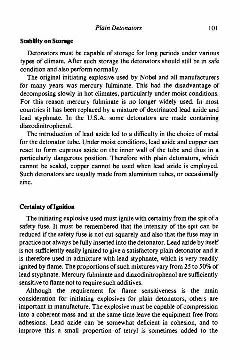
Plain Detonators 101
Stability on Storage
Detonators must be capable of storage for long periods under varioustypes of climate. After such storage the detonators should still be in safecondition and also perform normally.
The original initiating explosive used by Nobel and all manufacturersfor many years was mercury fulminate. This had the disadvantage ofdecomposing slowly in hot climates, particularly under moist conditions.For this reason mercury fulminate is no longer widely used. In mostcountries it has been replaced by a mixture of dextrinated lead azide andlead styphnate. In the U.S.A. some detonators are made containingdiazodinitrophenol.
The introduction of lead azide led to a difficulty in the choice of metalfor the detonator tube. Under moist conditions, lead azide and copper canreact to form cuprous azide on the inner wall of the tube and thus in aparticularly dangerous position. Therefore with plain detonators, whichcannot be sealed, copper cannot be used when lead azide is employed.Such detonators are usually made from aluminium tubes, or occasionallyzinc.
Certainty of Ignition
The initiating explosive used must ignite with certainty from the spit of asafety fuse. It must be remembered that the intensity of the spit can bereduced if the safety fuse is not cut squarely and also that the fuse may inpractice not always be fully inserted into the detonator. Lead azide by itselfis not sufficiently easily ignited to give a satisfactory plain detonator and itis therefore used in admixture with lead styphnate, which is very readilyignited by flame. The proportions of such mixtures vary from 25 to 50% oflead styphnate. Mercury fulminate and diazodinitrophenol are sufficientlysensitive to flame not to require such additives.
Although the requirement for flame sensitiveness is the mainconsideration for initiating explosives for plain detonators, others areimportant in manufacture. The explosive must be capable of compressioninto a coherent mass and at the same time leave the equipment free fromadhesions. Lead azide can be somewhat deficient in cohesion, and toimprove this a small proportion of tetryl is sometimes added to the
102 High Explosives
mixture. In Britain, but not in other countries, it is common practice to adda small proportion of fine flake aluminium to the mixture, the purposebeing to improve lubrication in the presses and to prevent adhesion to thepunches.
Initiating Power
To some extent detonators and blasting explosives are designedtogether so that one will initiate the other with certainty. Experience withfulminate detonators showed that the No. 6 detonator containing 1 g of amixture containing 80% mercury fulminate and 20% potassium chloratecould reliably initiate the nitroglycerine and TNT explosives in use. Such adetonator can be considered the normal minimum strength in mostcountries. Changes in design have, however, led to an overall increase instrength so that the No. 6 detonators now being sold are in fact morepowerful than the original.
For both technical and economic reasons, current detonators contain abase charge of high explosive which provides the main initiating power ofthe device. The most satisfactory high explosives for use as base chargesare PETN, tetryl and RDX, and of these the first is by far the commonest,because of its sensitiveness and relatively low cost.
The strength of the detonator depends to a large extent on the weight ofbase charge employed, but for a given weight of base charge the strengthmay be increased by the following measures:
1. Increasing the pressing of the base charge to give a higher density.This leads to a higher velocity of detonation and therefore greaterinitiating power.
2. Use of a narrower diameter tube. This leads to a longer length ofbase charge which in general is more effective in initiating blastingexplosives.
3. Increasing the thickness of the metal of the tube. Within limits thisgives greater confinement and therefore more effective detonationof the base charge.
In practice detonators of increased strength are made by increasing theweight of the base charge rather than by other means. The only importantexception to this is the German Briska detonator (see p. 103).

Plain Detonators
Construction of Plain Detonators
103
The general construction of a British plain detonator is shown in Fig.9.1; other countries in general adopt similar designs.
Priming charge
Base charge
FIG .9.1. Plain detonator.
The tube is of aluminium, 6-4 mm external diameter and with anoverall length of 35 mm; the wall thickness is O-3 mm. The base is dimpledinwards, as this construction gives a miniature cone charge and therefore asomewhat increased initiating power at the end of the detonator (see p.158). These tubes are made from aluminium sheet by drawing into cups,annealing and then drawing by several stages to the final size. Afterdrawing, the tubes are trimmed to length to give a neat open end. The tubelength is designed to give an unoccupied space of approximately 2-5 cm inthe finished detonator. In use the safety fuse is inserted into this portion ofthe tube, which is then crimped round the fuse to hold the assembly together.
The base charge consists of PETN and the No. 6 detonator contains0-24 g. The charge is pressed at 28 MPa, this pressure being chosen to giveadequate density and velocity of detonation without imposing undue strainon the tube with any liability of causing splitting. By use of a flat, ordimpled, punch, the surface of the base charge can be produced either flator with a conical depression. The latter construction gives advantages inthe initiation of the base charge, but by blocking of punches can give rise tomore frequent faults in manufacture.
In Briska-type detonators the base charge is loaded in two portions. Thefirst is pressed at about 140 MPa, the tubes being specially supported. Thesecond addition is pressed to a normal pressure and serves to initiate themore highly compressed explosive. In Britain it is preferred to increasedetonator strength by increasing the weight of charge; thus the strongest

104 High Explosives
commercial detonator (No. 8 Star) contains 0-8 g PETN in a tube ofslightly increased diameter.
The normal initiating charge in a British detonator is lead azide modifiedwith gelatine. In the case of plain detonators a small proportion of leadstyphnate is added to the azide to ensure satisfactory ignition from safetyfuse.
Manufacture
The tubes after manufacture are examined for any faults and thenloaded, open end uppermost, in holes of a carrying plate, usually 181 at atime. The plate is first placed in a charging machine for PETN. Thismachine has a charging plate with 181 holes of standard size. It rests on abase plate, also with 181 holes, but initially displaced from these holes byfinite horizontal distance. A charging hopper containing PETN is movedbackwards and forwards across the charging plate until the holes are full.The plate is then slid until the holes coincide with those of the base plate, sothat the PETN in measured volume drops through into the detonatortubes. The charging plate is then removed and placed under a press with181 punches, where the base charge is consolidated.
The ingredients for the priming composition are dried separately undercarefully controlled conditions. They are then weighed and carefullymixed behind blast protection, usually in a simple conical cloth bag. Themixing may be facilitated by adding a number of rubber balls. The mixtureis then passed through a coarse sieve, still by remote control, into bags fortransport to the loading unit.
The charging of the detonators with priming composition is carried outby a method similar to that used for the base charge, although thequantities involved are smaller and the volumes added similarly small.Again after charging, the charging plate is taken to a press where thepriming charge is compressed to a total load of about 15 tonnes. Bothcharging and pressing of the priming composition must be carried outunder full remote control.
The detonators as made may be dirty, that is have free primingcomposition as a dust on the walls. They are therefore transferred to adrum containing a quantity of dry sawdust. The drum is rotated for a
Plain Detonators 105
predetermined time and the detonators then removed and shaken free ofsawdust. In this way any free priming composition is removed and alsoany loose charges would be broken down. The detonators are thencarefully inspected and finally packed. Most detonators in Britain are nowmade on fully automatic equipment. The physical principles are the sameexcept that the final removal of loose priming composition is by vacuumcleaning.
Testing of Detonators
The essential property of a detonator is its initiating power, but this isvery difficult to measure. The best type of test is carried out bymanufacturing a series of explosives of decreasing sensitiveness andattempting to initiate them with the detonator under examination. The firstof these tests is known as the Esop test and employs picric acid as astandard explosive, gradually diluted with olive oil as a means of reducingsensitiveness, but the results depend critically on the grist of the picric acid.A rather more reproducible test has been based on milled TNT ammoniumnitrate explosives desensitised with salt. A standard range of suchexplosives is used, and for each composition the sensitiveness can befurther varied by pressing the explosive to a varying extent. In tests of thissort it is important to assess the detonation of the high explosive byindentation of a lead plate or by a lead crusher. Tests of the type describedhere are tedious to carry out and also give results which depend to someextent on the nature of the high explosive used.
For routine testing simpler tests can be employed. One such uses a leadplate 0-5 cm thick and resting on an iron support with a circular hole ofradius 18 mm. The detonator is fired when standing vertically on the plateabove the centre of the hole and in contact. The dent or hole in the leadplate is compared with a series of standard deformations from detonatorsof increasing strengths. This test measures only the end blow of thedetonators, whereas in initiating explosives the side blow can be at least asimportant. Another test commonly used is to fire a detonator lying on astandard iron nail and observing the bending produced in the nail. Such atest can give a rough indication of the side blow of the detonator. All testsof this sort should be used only for comparing constancy of manufacture

106 High Explosives
in a single type of detonator. Their use in comparing detonators of differentconstructions can be grossly misleading.
Reference
MARSHALL, A., Explosives Vol. 2, Properties and Tests. Churchill, London, 2nd ed. 1917.

CHAPTER 10
Electric Detonators
ELECTRIC detonators consist of plain detonators to which a device hasbeen added for generating a flash on receipt of an electric impulse. The firstdevices of this sort were invented by Watson in England and BenjaminFranklin in the U.S.A. and utilised electric sparks for igniting gunpowdercharges. The modern method of igniting a flashing composition by passingthe electric current through a fine wire was invented by Hair in 1832.Suitable ignition systems were therefore available long before detonatorsthemselves were invented.
It is convenient to distinguish four systems by which the electricalenergy can be converted into a flash.
1. A bridge of resistance wire is connected across the ends of twoleading wires and surrounded by a loose charge of flashingcomposition or of initiating explosive.
2. A bridgewire similarly attached to the ends of leading wires iscoated with a coherent layer or layers of flashing materials.
3. The leading wires are attached to a fusehead, originally a separateentity and containing a bridgewire surrounded by coatings offlashing composition.
4. The leading wires are again attached to a fusehead, but thiscontains no resistance wire, having a flashing composition which isitself made sufficiently conducting to ignite when a high voltage isplaced across it.
The construction of these types is shown in Fig. 10.1 (p. 108).Type 4 gives a high tension detonator, so called because it requires at
least 36 volts to fire it. The electrical conductivity is achieved by addinggraphite to the flashing composition, but control of electrical properties isdifficult and the finished product liable to change on mechanical handlingor on storage. For this reason detonators of this type are no longeremployed. 1Q7

108 High Explosives
Detonators of the first three types all employ bridgewires and thereforerequire low voltages for their initiation. The choice is one of manufacturingconvenience, but as most makers prefer type 3, only this will be describedin detail.
Fuseheads
Bridge wires
Type 1 2 3 4
FIG . 10.1. Types of detonator ignition systems.
The flashing device, without leading wires, is known as a fusehead andits construction and properties will be considered first.
Fuseheads
The first successful type of fusehead was invented by Krannichfeldt inGermany. This "sandwich" type of construction is used in manycountries, including Great Britain, and is illustrated in Fig. 10.2.
The manufacture of a sandwich fusehead proceeds in the followingmanner. Brass or other metal foils are fixed on each side of a sheet ofpressboard with a suitable adhesive. The pressboard is then stamped intocombs of the shape shown in Fig. 10.3 and steps are cut in the tips of theheads. Fine resistance wire is stretched across the heads and soldered tothe foil on each side of the pressboard. These operations were originally allcarried out by hand; now many are carried out mechanically.
A number of these combs are fixed side by side with spacers in acarrying plate. The tips of the combs are then dipped into a solution ofpaint-like consistency containing flashing compositions to be described
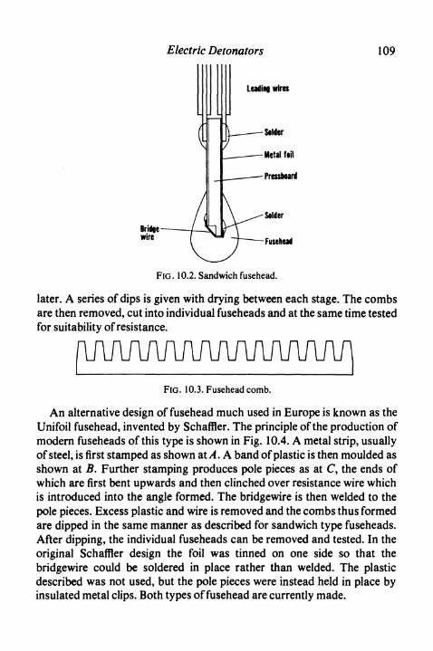
Electric Detonators 109
Leading wires
FIG. 10.2. Sandwich fusehead.
later. A series of dips is given with drying between each stage. The combsare then removed, cut into individual fuseheads and at the same time testedfor suitability of resistance.
f\M/WWWW\AA/inFIG. 10.3. Fusehead comb.
An alternative design of fusehead much used in Europe is known as theUnifoil fusehead, invented by Schaffler. The principle of the production ofmodern fuseheads of this type is shown in Fig. 10.4. A metal strip, usuallyof steel, is first stamped as shown at A. A band of plastic is then moulded asshown at B. Further stamping produces pole pieces as at C, the ends ofwhich are first bent upwards and then clinched over resistance wire whichis introduced into the angle formed. The bridgewire is then welded to thepole pieces. Excess plastic and wire is removed and the combs thus formedare dipped in the same manner as described for sandwich type fuseheads.After dipping, the individual fuseheads can be removed and tested. In theoriginal Schaffler design the foil was tinned on one side so that thebridgewire could be soldered in place rather than welded. The plasticdescribed was not used, but the pole pieces were instead held in place byinsulated metal clips. Both types of fusehead are currently made.
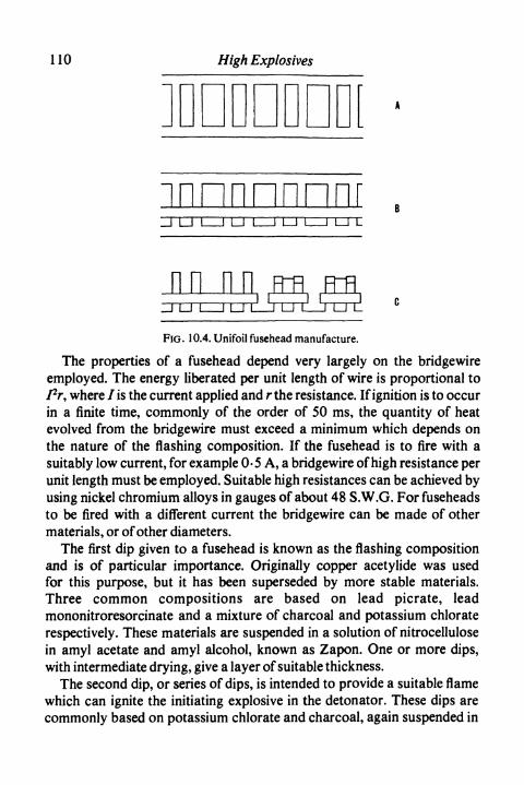
110 High Explosives
innnnnnnrLJ L
nn nnFIG. 10.4. Unifoil fusehead manufacture.
The properties of a fusehead depend very largely on the bridgewireemployed. The energy liberated per unit length of wire is proportional toPr, where 7 is the current applied and r the resistance. If ignition is to occurin a finite time, commonly of the order of 50 ms, the quantity of heatevolved from the bridgewire must exceed a minimum which depends onthe nature of the flashing composition. If the fusehead is to fire with asuitably low current, for example 0-5 A, a bridgewire of high resistance perunit length must be employed. Suitable high resistances can be achieved byusing nickel chromium alloys in gauges of about 48 S.W.G. For fuseheadsto be fired with a different current the bridgewire can be made of othermaterials, or of other diameters.
The first dip given to a fusehead is known as the flashing compositionand is of particular importance. Originally copper acetylide was usedfor this purpose, but it has been superseded by more stable materials.Three common compositions are based on lead picrate, leadmononitroresorcinate and a mixture of charcoal and potassium chloraterespectively. These materials are suspended in a solution of nitrocellulosein amyl acetate and amyl alcohol, known as Zapon. One or more dips,with intermediate drying, give a layer of suitable thickness.
The second dip, or series of dips, is intended to provide a suitable flamewhich can ignite the initiating explosive in the detonator. These dips arecommonly based on potassium chlorate and charcoal, again suspended in

Electric Detonators 1 1 1
Zapon. The fusehead is finally given a coat of a nitrocellulose solution as aprotective layer and this coat may well be coloured with pigment so thatthe type of fusehead can readily be identified.
Assembly of Electric Detonators
Leading wires are made from tinned iron or copper, of gauges from 23to 25 S.W.G. They are insulated with plastic, commonly PVC, coloured toenable different types of detonator to be readily distinguished. Two suchwires are wound, usually by machine, to form figure eight coils of totallengths ranging from 1-2 to 5-5 m, according to requirements. The coilsare held together by a few turns of the two leading wires around the bundle.The four ends of wires are stripped of insulation to a suitable distance.
Leading wires
Fusehead
Priming charge
Base charge
FIG. 10.5. Electric detonator.
A small cylindrical plug is fixed near one end of the leading wires, eitherby threading on a pre-formed plug, or by moulding plastic around thewires at a suitable point. The bared ends of the wires immediately adjacentto the plug are then soldered to the two conducting foils of the fusehead. Inthe case of Unifoil fuseheads the wires are soldered or welded to the metaltags. The completed assembly is then inserted to the correct depth inside aplain detonator and the tube crimped round the plug to hold the detonator
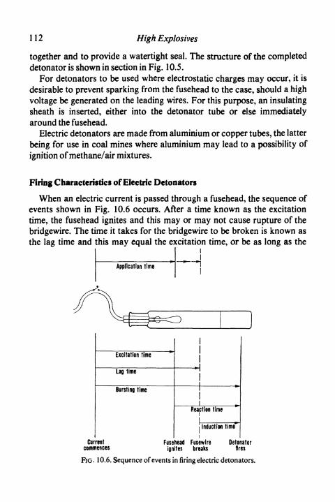
112 High Explosives
together and to provide a watertight seal. The structure of the completeddetonator is shown in section in Fig. 10.5.
For detonators to be used where electrostatic charges may occur, it isdesirable to prevent sparking from the fusehead to the case, should a highvoltage be generated on the leading wires. For this purpose, an insulatingsheath is inserted, either into the detonator tube or else immediatelyaround the fusehead.
Electric detonators are made from aluminium or copper tubes, the latterbeing for use in coal mines where aluminium may lead to a possibility ofignition of methane/air mixtures.
Firing Characteristics of Electric Detonators
When an electric current is passed through a fusehead, the sequence ofevents shown in Fig. 10.6 occurs. After a time known as the excitationtime, the fusehead ignites and this may or may not cause rupture of thebridgewire. The time it takes for the bridgewire to be broken is known asthe lag time and this may equal the excitation time, or be as long as the
Excitation time ""
Lag time
Bursting time
rent Fusenences jgn
Reaction time
Induction time*i
lead Fusewire Detonites breaks fire
FtG. 10.6. Sequence of events in firing electric detonators.

Electric Detonators 113
bursting time, which is the time between the application of current andthe explosion of the detonator. The interval between the ignition of thefusehead and the bursting of the detonator is known as the reaction timeand the interval between the breaking of the fuse wire and the bursting ofthe detonator is known as the induction time.
For any particular kind of fusehead these times depend on themagnitude of the electric current applied. If a steady current, less than theminimum firing current of the fusehead, is applied, the bridgewire does notget hot enough to ignite the flashing dip, so that the fusehead remains un-affected. As the magnitude of the current is increased, the fusehead igniteswith gradually reduced excitation times and therefore with gradualreduction in overall bursting time. In applications where short burstingtimes are essential, as in seismographic work, not only are specialdetonators used, but the firing currents employed are maintained as highas possible.
Although steady currents are sometimes applied to fire detonators, it isequally common to use exploders which have a finite time of currentapplication. This may be either incidental, because the mechanism is thedischarge of a charged condenser, or deliberate in the case of coal miningapplications where finite time of pulse is desirable for safety reasons. Suchfinite pulse times, usually of the order of 4 to 5 ms, prevent the possibilityof later sparking between leading wires, etc., in the presence of methane/airmixtures. When a pulse of current is used to fire a detonator, the time forwhich it is applied is known as the application time. If the detonator is to befired successfully, the magnitude of the current must be such that theapplication time of the exploder exceeds the corresponding excitation timeof the fusehead.
When a large number of shots are to be fired it is common practice toconnect the electric detonators in series and fire them all with the singleapplication of an exploder. The current from the exploder ceases when thefirst fuse wire breaks and therefore at the time of the shortest lag time of thedetonators involved. This time will depend on the magnitude of the firingcurrent, as shown in Fig. 10.7. In this figure the curve A represents theminimum lag time shown by any detonator in a large number selectedfrom those made to a single specification. Owing to minor variations in in-gredients, etc., during manufacture, the average lag time will be at eachpoint longer than that shown on the curve. Also shown in Fig.-10.7 incurve C is the maximum excitation time characteristic of the fuseheads in-
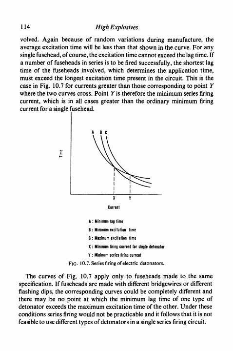
114 High Explosives
volved. Again because of random variations during manufacture, theaverage excitation time will be less than that shown in the curve. For anysingle fusehead, of course, the excitation time cannot exceed the lag time. Ifa number of fuseheads in series is to be fired successfully, the shortest lagtime of the fuseheads involved, which determines the application time,must exceed the longest excitation time present in the circuit. This is thecase in Fig. 10.7 for currents greater than those corresponding to point Ywhere the two curves cross. Point Y is therefore the minimum series firingcurrent, which is in all cases greater than the ordinary minimum firingcurrent for a single fusehead.
A B C
X Y
Current
A : Minimum lag time
B : Minimum excitation time
C : Maximum excitation time
X : Minimum firing current for single detonator
Y : Minimum series tiring current
FIG. 10.7. Series firing of electric detonators.
The curves of Fig. 10.7 apply only to fuseheads made to the samespecification. If fuseheads are made with different bridgewires or differentflashing dips, the corresponding curves could be completely different andthere may be no point at which the minimum lag time of one type ofdetonator exceeds the maximum excitation time of the other. Under theseconditions series firing would not be practicable and it follows that it is notfeasible to use different types of detonators in a single series firing circuit.
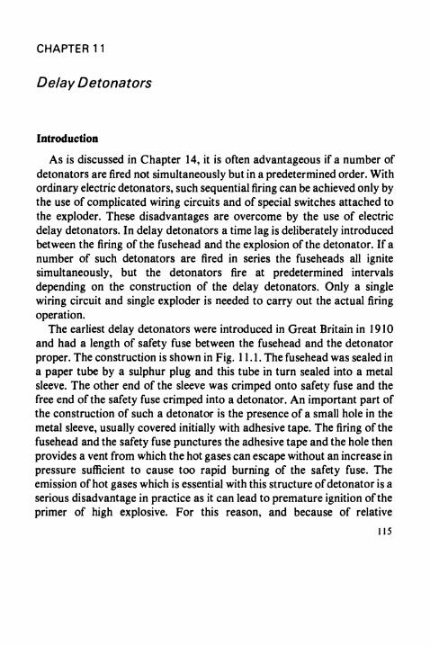
CHAPTER 11
Delay Detonators
Introduction
As is discussed in Chapter 14, it is often advantageous if a number ofdetonators are fired not simultaneously but in a predetermined order. Withordinary electric detonators, such sequential firing can be achieved only bythe use of complicated wiring circuits and of special switches attached tothe exploder. These disadvantages are overcome by the use of electricdelay detonators. In delay detonators a time lag is deliberately introducedbetween the firing of the fusehead and the explosion of the detonator. If anumber of such detonators are fired in series the fuseheads all ignitesimultaneously, but the detonators fire at predetermined intervalsdepending on the construction of the delay detonators. Only a singlewiring circuit and single exploder is needed to carry out the actual firingoperation.
The earliest delay detonators were introduced in Great Britain in 1910and had a length of safety fuse between the fusehead and the detonatorproper. The construction is shown in Fig. 11.1. The fusehead was sealed ina paper tube by a sulphur plug and this tube in turn sealed into a metalsleeve. The other end of the sleeve was crimped onto safety fuse and thefree end of the safety fuse crimped into a detonator. An important part ofthe construction of such a detonator is the presence of a small hole in themetal sleeve, usually covered initially with adhesive tape. The firing of thefusehead and the safety fuse punctures the adhesive tape and the hole thenprovides a vent from which the hot gases can escape without an increase inpressure sufficient to cause too rapid burning of the safety fuse. Theemission of hot gases which is essential with this structure of detonator is aserious disadvantage in practice as it can lead to premature ignition of theprimer of high explosive. For this reason, and because of relative
115

116 High Explosives
inaccuracy in delay times, this type of delay detonator is now only rarelyused.
A real advance in the construction of delay detonators was made byEschbach, who introduced delay compositions which evolved so little gasthat there was no longer need to vent the detonator. This eliminated risk ofpre-ignition of high explosive and also made it possible to provide fullywaterproofed assemblies which gave delay times much more regularbecause of the removal of variable venting effects. Delay detonators of thistype have now virtually superseded all others.
Waterproofing Vent Rubberised tape
^^<}A\^^====-=^=^--M%22%j^^^-^J^.^^^^^^-^^^ ^VT^V, \///r< /A
\/ \ \ /Sulphur Fusehead Safety fuse Detonating explosive
(a) Early vented delay detonator
Neoprene plug Fusehead Delay Priming Baseelement charge charge
(b) Modern delay detonator
FIG .11.1. Construction of delay detonators.
Gasless delay detonators are manufactured to fire after pre-arrangeddelay times, each manufacturer providing a series of detonators withintervals of usually 1 s or 0.5 s. More recently a further type of delaydetonator has been introduced, usually known as the millisecond, or shortdelay detonator. Again, manufacturers provide a series of fixed delaytimes, but in this case the interval between each number of the series ismuch shorter and may be from 25 to 50 ms.

Delay Detonators 117
Delay Compositions
The mixtures used in providing delay elements contain an easilyoxidised element, often a finely divided metal, together with an oxy-salt oran easily reduced metal oxide. The first of such mixtures to attain wide usewas that employed by Eschbach and consisted of a mixture of elementalantimony and potassium permanganate. When such a mixture is ignited,the antimony is oxidised to antimony oxide and the potassiumpermanganate reduced either to the manganate or to a mixture ofpotassium and manganese oxides, depending on the proportions present.Whilst a little gas is formed in a side reaction of permanganatedecomposition, the amount is small and the pressure developed inside adetonator is not large. The reaction products form a solid slag ofindeterminate composition. The proportions commonly used vary from 55to 70% of permanganate with 45-30% of antimony.
In the U.S.A. a common mixture for delay elements consists of seleniumand barium peroxide which reacts to give selenium oxides and barium oxide.Usual proportions are 85% of barium peroxide with 15% of selenium.
For the manufacture of millisecond delay detonators, faster burningcompositions are necessary. Many have been suggested, but the two mostcommonly used are based on silicon mixed with either red lead or leaddioxide. Typical mixtures would contain between 30 and 50% of siliconand the remainder as oxidising material.
The burning of a column of delay composition takes place by thepassage of a reaction front along the column. The temperature profile ofthis reaction front can be measured by the use of suitable thermocouplesand recording instruments. By analysing the shape of the front it can beshown that the reaction is a solid/solid reaction initiated by thermalconduction of heat through the unreacted material. It follows that toobtain reproducible reaction rates there must be (1) constant amount ofsolid to solid contact and (2) constant thermal conductivity.
To attain adequate surface contact between the reacting solids it isnecessary to use the ingredients in fine condition and to bring them intocontact by pressure. To maintain both solid contact and thermalconductivity correct, the density of the column is controlled at a uniformvalue. The manufacture of satisfactory delay compositions, therefore,entails the provision of suitably sized ingredients followed by adequatemixing and accurate pressing.
118 High Explosives
Manufacture of Delay Elements
Delay compositions are not normally pressed direct into detonatorshells because of the irregular delay times which result from the relativelylow compression thus possible. Instead they are made into delay elementsby either of two basic methods. The more general method comprisespressing into brass or aluminium tubes which are a sliding fit into thedetonator shell and which are thick enough in the wall to withstand heavyconsolidating pressures. The other method consists of filling a lead tubewith the delay composition and drawing it down in diameter byconventional means. This process gives a length of lead tube filled withdelay composition ready for cutting into the required lengths. The processof drawing itself consolidates the delay composition.
For either method, the delay composition must be made in a free-flowing form. In the case of the antimony/potassium permanganatemixtures, this is done by mixing fine antimony and fine potassiumpermanganate and then pelleting the mixture in a press. The pellets arethen broken down and after sieving to remove fines a suitable free flowinggranule is obtained. For other types of compositions this method is notgenerally applicable because of the difficulty of forming pellets bypressure. Instead the mixture is granulated with a small amount ofnitrocellulose solution by working in a suitable mixer.
The actual filling of brass or aluminium delay elements is similar inprinciple to the filling of plain detonators described above. The loading is,however, carried out in a number of stages so as to ensure uniformity ofdensity of the column throughout its length.
The manufacture of lead elements commences with the filling of a leadtube, probably 1 m long, by tamping in delay composition. This tube isgradually drawn down until it is of the correct external diameter to be asliding fit into the detonator shell. It is then accurately cut to the lengthsrequired to give the delay times.
Assembly of Delay Detonators
Assembly commences with a plain detonator containing its base chargeand initiating explosive. These detonators are held in plates and theprocesses are insertion of suitable delay elements, followed by pressing inthe normal way. They are then checked by X-ray examination to ensure

Delay Detonators 119
proper assembly. A fusehead, complete with plug and leading wires, isplaced in position in each detonator and crimped to give the finishedproduct.
Design of Delay Detonators
Some special points of design may be noted. Thus, some delaycompositions, particularly antimony/potassium permanganate mixtures,have relatively poor igniting powers for initiating explosives. This can becontrolled by suitable design of the delay elements, or alternatively, anintermediate layer of priming explosive of high sensitiveness, such as leadstyphnate, can be introduced between the element and the lead azidecharge. Another point to be watched is the possibility of "flash past",particularly in the shorter delay periods where the lengths of the elementsused are at a minimum. In the past it has sometimes been the custom tointroduce a layer of delay composition above the initiating explosivebefore placing in the delay element. Nowadays, however, improved overalldesign and technique has made this unnecessary.
Some delay compositions are difficult to ignite and ordinary fuseheadsmay not be adequate for this purpose. In such cases special fuseheads areused which commonly contain cerium powder, or some similar additivewhich burns with the evolution of a large amount of heat.
In the design of the detonator attention must also be paid to the effects ofthe liberation of gas which, though small, is still sufficient to requireattention. As the speed of the delay composition is affected by pressure, itis necessary that the free space in the detonator should be carefullycontrolled. Also, the plug which seals the leading wires in place mustwithstand this pressure for more than the delay period of the detonator.This task is made more difficult by conduction, along the metal walls of thedetonator shell, of heat liberated by the fusehead and the delaycomposition. Plastic plugs in particular are liable to soften and be ejectedfrom the detonator with probable failure of burning of the delay column.
Delay detonators for use in coal mines must be constructed so as not toignite methane/air mixtures even if fired accidentally outside a cartridge ofa blasting explosive. This requires a suitable selection of fusehead and theprovision of the delay element in a form which will not produce largeparticles of hot slag on burning. In the British design the delay elements are

120 High Explosives
of the lead type, but with five or six narrow cores instead of the singlecentral column. Such "Carrick" detonators will satisfy even the rigorousBritish test, which involves firing the detonators in a simulated break,formed by two steel plates 5 to 15 cm apart and filled with methane/airmixture.
CHAPTER 12
Detonating Fuse
Introduction
A detonating fuse is a narrow cord of explosive which is capable ofdetonating from one end to the other at high velocity and therefore oftransmitting detonation almost instantaneously from one cartridge toanother some distance away. The thinness of detonating fuse makes itessential to use explosives which are capable of propagating reliably atsuch small diameters. The earliest fuses of this sort were made with eitherdry nitrocellulose or more commonly with mercury fulminatephlegmatised with wax. Such fuses were irregular and dangerous in use asthey were sensitive to initiation by shock. The first successful detonatingfuse was Cordeau, which was made in the following manner. TNT wascast into a lead tube and allowed to solidify. The whole tube was thendrawn down to a diameter of 4 mm. This drawing process at the same timebroke down the cast TNT and brought it into a sensitive form which wouldpropagate whilst still confined by the lead tube. Cordeau had a uniformvelocity of detonation of about 5000 m s"1 and was also safe to handle.
From about 1930 onwards a new type of detonating fuse appeared onthe market. This consisted of a core of PETN with textile and plasticcoatings. Compared with Cordeau, this detonating fuse has severaladvantages in being more flexible, more easily jointed, lighter in weight andcheaper to manufacture. Under such names as Cordtex and Primacord ithas completely replaced Cordeau in normal use.
Detonating fuse is made by either a dry process or a wet process. Theformer is generally more popular because of its lower costs for ordinarytypes of fuse. The latter is, however, used particularly in North America.
121
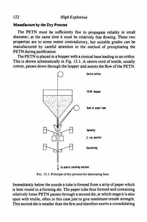
122 High Explosives
Manufacture by the Dry Process
The PETN must be sufficiently fine to propagate reliably in smalldiameter; at the same time it must be relatively free flowing. These twoproperties are to some extent contradictory, but suitable grades can bemanufactured by careful attention to the method of precipitating thePETN during purification.
The PETN is placed in a hopper with a conical base leading to an orifice.This is shown schematically in Fig. 12.1. A centre cord of textile, usuallycotton, passes down through the hopper and assists the flow of the PETN.
Centre cotton
PETN Hopper
Reel of paper tape
Spinning
-ray monitor
Countering
1 To plastic covering machine
FIG . 12.1. Principle of dry process for detonating fuse.
Immediately below the nozzle a tube is formed from a strip of paper whichis bent round in a forming die. The paper tube thus formed and containingrelatively loose PETN passes through a second die, at which stage it is alsospun with textile, often in this case jute to give maximum tensile strength.This second die is smaller than the first and therefore exerts a consolidating
Detonating Fuse 123
effect on the core of the fuse. The fuse is finally countered and covered withplastic by extrusion.
In any process for manufacturing detonating fuse it is important toascertain that there are no gaps in the PETN core. Such gaps would causefailure of the fuse to propagate detonation. A test is therefore done, eitherwith a roller diameter detector or by beta-ray monitor to determine thepresence of the core. The roller diameter detector consists of two spring-loaded rollers which approach each other in the absence of a core andindicate the fault. A beta-ray monitor determines the total weight of matterin the fuse by measuring its beta-ray absorption. Any lack of a core then isindicated in an alarm or other device. The fuse is also examined at variousstages of manufacture for flaws in textile or plastic covering.
Manufacture of Detonating Fuseby the Wet Process
The PETN used in the wet process is finer than that required for the dryprocess. It is no longer required to flow freely in the solid dry condition, butis suspended to a fluid paste in water with a suspending agent. This paste isthen braided with textile fibre and dried in a continuous drier. Theremaining stages in the process consist of countering with textile, coveringwith plastic and possibly final braiding. The speed of operation isdetermined by the rate of drying of the PETN paste and is therefore slowerthan that of the dry process where the limiting speed is usually theoperation of the countering machinery.
Properties of Detonating Fuse
The velocity of detonation of a fuse is about 6500 m s"1. This is attainedin the dry process by adequate consolidation of the core duringmanufacture. During the wet process the necessary density is attainedautomatically by the method of preparing the core. Fuse usually containsabout 10 g PETN per metre length.
A satisfactory fuse must be capable of propagating laterally from oneline to another. In this way it is practicable to join lengths of fuse byordinary knots, such as the reef knot. In test, the usual method is-to lay twostrands of fuse at a measured distance apart and ascertain that one

124 High Explosives
initiates the other. The gaps necessary for satisfactory use are small and inthe region of 6 mm. Alternatively, the test can be for propagation betweenfuses separated by varied thicknesses of card.
The tensile strength of the fuse is of some importance, as it is commonpractice to lower charges down a large hole by means of the detonatingfuse. A strength of 35 kg is adequate, but higher strengths can be achievedwhen necessary by the addition of further amounts of textile.
Further properties which a detonating fuse should have are the ability toinitiate blasting explosives (tested with suitable relatively insensitivemixtures usually of TNT and ammonium nitrate); resistance to lowtemperatures without cracking on flexing and to hot storage withoutdesensitisation; and toughness to prevent damage from stones, etc. Thefuse must always be waterproof and must often withstand diesel oil, whichcan separate from ANFO.
Low Energy Detonating Cord (LEDC)
When detonating cord is not required directly to initiate high explosives,but solely to transmit detonation from one place to another, it is sometimesan advantage to use a cord with a very low charge weight. Two types ofsuch cord are at present available in certain countries.
The first type to be introduced consisted of PETN or RDX in a metalsheath drawn down to a small diameter. More recently, cord made by thewet process, covered with plastic instead of metal, has been introduced inNorth America and is available in charges down to 0-6 g nr1. Themethods of manufacture of these cords are believed to be similar to that ofCordeau and the wet detonating fuse process described above.
When used for laying above ground for connecting shots in civilengineering, quarrying, etc., a low energy detonating cord has theadvantage of producing much less noise than the normal grade. Thisavoids any requirement of covering the cord with earth or sand when usedin populous areas. Another use for the cord, particularly the plasticvariety, is in connection with blasting with ANFO. The cord itself hasinsufficient initiating power to cause ANFO to detonate and can beattached to a special delay detonator. In this way propagation betweenholes by detonating fuse can be achieved with the extra advantage of theintroduction of suitable delay times between individual holes. The

Detonating Fuse 125
particular advantage of this method with ANFO is the absence of electricfuses and therefore complete safety in dry conditions where staticelectricity may be generated. Special connectors must be used if LEDC isto be joined to ordinary detonating fuse.
Nonel
As the loading density of a powdered solid explosive is reduced thedetonation velocity becomes less. This follows from equation (5) ofChapter 2, asp2 is smaller the lower the density. Calculation shows that atthe lowest densities the detonation velocity tends towards a limiting lowervalue, typically about 2000 m s-1. This is also the detonation velocity in adust explosion of these substances.
Nonel fuse, invented by Nitro Nobel AB in Sweden, consists of a thickplastic tube of bore about 1 mm, the inside surface of which is dusted witha small amount of powdered high explosive. If a shock wave is formed atone end of the tube the explosive powder is raised to a dust and a stabledetonation at velocity 2000 m s"1 proceeds indefinitely along the fuse. Theplastic itself is unaffected and the only outside effect is a flash of light seenthrough the tube walls. This therefore is an extremely safe method ofpropagating a detonation from one place to another.
In practice lengths of fuse are supplied sealed in the factory to preventingress of dust or moisture. The detonation may be started in various wayssuch as a small detonator or by firing a blank cartridge. At the other end ofthe fuse the flash is sufficient to ignite the priming explosive of a plaindetonator or the delay element of a delay detonator. Plastic mouldings areavailable so that branch lines may be introduced. It is therefore possible tofire from one point any number of detonators in any predetermined delaysequence. The system is very simple to operate and is immune to strayelectric currents in the ground due to electric circuits or lightningdischarges.
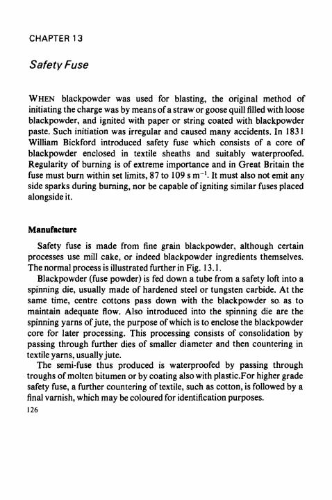
CHAPTER 13
Safety Fuse
WHEN blackpowder was used for blasting, the original method ofinitiating the charge was by means of a straw or goose quill filled with looseblackpowder, and ignited with paper or string coated with blackpowderpaste. Such initiation was irregular and caused many accidents. In 1831William Bickford introduced safety fuse which consists of a core ofblackpowder enclosed in textile sheaths and suitably waterproofed.Regularity of burning is of extreme importance and in Great Britain thefuse must burn within set limits, 87 to 109 s m"1. It must also not emit anyside sparks during burning, nor be capable of igniting similar fuses placedalongside it.
Manufacture
Safety fuse is made from fine grain blackpowder, although certainprocesses use mill cake, or indeed blackpowder ingredients themselves.The normal process is illustrated further in Fig. 13.1.
Blackpowder (fuse powder) is fed down a tube from a safety loft into aspinning die, usually made of hardened steel or tungsten carbide. At thesame time, centre cottons pass down with the blackpowder so as tomaintain adequate flow. Also introduced into the spinning die are thespinning yarns of jute, the purpose of which is to enclose the blackpowdercore for later processing. This processing consists of consolidation bypassing through further dies of smaller diameter and then countering intextile yarns, usually jute.
The semi-fuse thus produced is waterproofed by passing throughtroughs of molten bitumen or by coating also with plastic.For higher gradesafety fuse, a further countering of textile, such as cotton, is followed by afinal varnish, which may be coloured for identification purposes.126
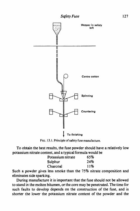
SqfetyFuse 127
Hopper in safetyloft
) Centre cotton
Spinning
Countering
To finishing
FIG .13.1. Principle of safety fuse manufacture.
To obtain the best results, the fuse powder should have a relatively lowpotassium nitrate content, and a typical formula would be
Potassium nitrate 65%Sulphur 24%Charcoal 11%
Such a powder gives less smoke than the 75% nitrate composition andeliminates side sparking.
During manufacture it is important that the fuse should not be allowedto stand in the molten bitumen, or the core may be penetrated. The time forsuch faults to develop depends on the construction of the fuse, and isshorter the lower the potassium nitrate content of the powder and the
128 High Explosives
thinner the covering of textile provided by the spinning and counteringyarns.
To maintain regularity of burning speed it is essential that high qualityfuse powder is employed. It is normal to determine the quality fromsamples before use and this is conveniently done by filling the powder intoa lead tube, which is then rolled down to a small diameter. The regularity ofburning of the lead fuse is then determined. If a high-grade powder isemployed, then regularity of burning of the finished fuse may be securedprovided that sufficient attention is paid to giving regular confinement bycontrol of the construction of the envelope.
Safety fuse covered only with bitumen can be used with care in dryconditions but normal practice requires better protection from roughhandling and moisture. For many years this was given by gutta percha andtextiles but the former material is no longer readily available. Coatings ofplastic such as polyethylene are now used. Early products had thedisadvantage of speeding up in burning under water and causingirregularity of firing of shotholes under wet conditions. This defect hasbeen removed by careful design. Current fuses therefore have excellentresistance not only to abrasion and water but also to the fuel oil in ANFO.
In the Fritzsche process blackpowder is not employed, but only themixed ingredients of potassium nitrate, sulphur and charcoal. These arefed into the process by special methods, but the final construction and useof the fuse remain unchanged.
Properties of Safety Fuse
As the blackpowder core of a safety fuse burns, it produces gases whichmust escape. At the same time the heat of the combustion melts thebitumen and plastic and thus produces side venting through the textilelayers. This results in the production of an increased but constant gaspressure, determined by the equilibrium between gas generation and gaslost sideways. As the rate of burning of blackpowder depends markedly onthe pressure, it is this process of equilibration which determines the speedof burning of the fuse.
With a properly constructed safety fuse the core is almost impermeableto gases, but should faults occur, either during manufacture or due tomishandling afterwards, cracks may develop which enable the hot gases to
Safety Fuse 129
penetrate forward. In this case the speed of the burning of the safety fusecan increase and even become violent.
It follows also that the actual rate of burning of safety fuse depends onthe ambient pressure. Indeed, if the pressure is reduced to less than about afifth of an atmosphere the burning ceases altogether. In deep mines theextra pressure can be sufficient to give an increase in burning speed ofsafety fuse. Compared with the effect of pressure other influences on theburning speed are small. Temperature has little effect and humidity alsohas little effect unless the fuse is kept for a prolonged period at a humiditysufficient to cause deliquescence of the potassium nitrate in the core.
The gas evolved by safety fuse consists mainly of carbon dioxide andnitrogen with some carbon monoxide and oxides of nitrogen. The amountof gas produced is likely to be 15 to 20 ml per cm of fuse.
Testing of Safety Fuse
Because of the extreme importance of regularity and freedom fromfailure which must characterise safety fuse, detailed and exhaustive testsmust be carried out on the product. Certain controls are obvious, namely,measurement of powder charge and of burning speed, both before andafter immersion in water. Other tests usually carried out include resistanceto cracking on flexing at low temperatures round a mandrel, "coil" tests inwhich the fuse is bunched into flat or complex coils and freedom fromfailure after immersion in water is determined. New types of fuse areusually tested to indicate the amount of smoke produced and also todetermine the adequacy of the end spit. The end spit is the projection ofparticles of burning powder from a cut end and is of importance because itprovides the mechanism which enables the fuse to ignite a detonator.
Instantaneous Fuse
For some purposes, particularly in fireworks, instantaneous or almostinstantaneous transmission of flame is required without detonation such asis characteristic of detonating fuse. Instantaneous fuse is used for thispurpose, deliberate use being made of one of the possible faults in safetyfuse, namely, the rapid speeding up which can occur if the core of thesafety fuse is porous.

130 High Explosives
Instantaneous fuse consists of a highly combustible thread, often madefrom nitrated paper, inside a tube of known diameter. The nitrated paperoccupies only a small part of the cross section of the tube, so that the gasescan penetrate along it freely. The high speed of burning is caused by therapid passage of hot gases along the tube, igniting the core well in front ofthe portion already consumed. The rate of burning is not easily controlled,but the uses to which the fuse is put are such that this is not of greatimportance. Threads coated with blackpowder may be used in place of anitrated paper core. Instantaneous fuse is usually made only in smallquantities by simple hand methods.
Igniter Cord
If the outer covers of safety fuse are pierced, e.g. by falling rock, watercan penetrate and stop the combustion of the fuse. Much work has beendone in efforts to obtain a waterproof fuse which will obviate this difficulty.This work, although not successful in its original purpose, has led to thedevelopment of igniter cord which has proved of considerable value insecondary blasting (see p. 148). Two types of igniter cord are manu-factured, fast cord with a burning speed of 3 s m"1 and slow cord with aspeed of 30 s m"1.
In the manufacture of fast cord the first process is to coat paper ortextile yarns with a blackpowder/nitrocellulose dope by a dipping process.These yarns are thoroughly dried and a number of them passed through anextruder and given a thick covering of plastic incendiary composition. Thecord thus produced is covered with a protective layer of plastic, usuallypolyethylene. The overall diameter of the cord is about 2-5 mm.
The speed of burning of fast igniter cord depends on the speed ofburning of the blackpowder-coated yarns and this depends in turn on thegas channels left in the construction of the fuse. The remainder of the fuseis also combustible, so that there is no pressure build up due to lack ofventing. Should a minor pin hole or break in the outside layers be producedand water enter, the incendiary composition will continue to burn so thatthe fuse will not fail, although it will slow down for the distance of thedamage.
Slow igniter cord consists of the same type of plastic incendiarycomposition extruded not over combustible blackpowder-coated yarns,

Safety Fuse 131
but over a metallic wire. The function of the wire is to conduct heat fromthe burning front into unburnt composition and so control and speed upthe rate of burning of the igniter cord. This centre is usually of copper, butmay be of iron or aluminium. Slow igniter cord is covered with a thin layerof protective plastic.
The basis of igniter cords is the incendiary plastic. Of the possiblecompositions those which have achieved most importance are based on anitrocellulose binder with oxidising and combustible additives. Thenitrocellulose is normally plasticised with dibutylphthalate and containsalso the usual stabilisers. A low viscosity lacquer grade of nitrocellulose ismost conveniently employed. The oxidising components consist of abalanced mixture of red lead with either potassium nitrate or potassiumperchlorate. The addition of a potassium salt is found to give certainty ofpick up of flame and suitable vigour in combustion, but its quantity isrestricted by the requirement that the finished product should be safeunder conditions of impact such as can occur in use. The combustibleadditive is usually finely divided silicon. The incendiary composition isthermoplastic and extruded hot. In bulk it can burn vigorously andtherefore special safety precautions are required in processing, includingautomatic guillotines to cut the fuse at suitable points in case of fire.
Igniter cord is used for the purpose of igniting a number of lengths ofsafety fuse at predetermined intervals. Special connectors are thereforesupplied for transmitting the flame from the igniter cord to the safety fuse.The connector consists of an aluminium tube, closed at one end, intowhich a pellet of incendiary composition is pressed. An elliptical "beanhole" is then cut through the two sides of the tube and the composition. Inuse, the connector is crimped to the cut end of safety fuse; the igniter cordis then bent double and the doubled portion passed through the bean hole,which is crimped firmly with a special tool. The side flame from the ignitercord sets fire to the incendiary composition in the connector and this inturn ignites the safety fuse. Some designs of connector contain alsoblackpowder to assist propagation of the flame, but such connectors aregenerally employed only when supplied from the factory already fastenedto lengths of safety fuse so that there is no danger of penetration ofmoisture to the blackpowder during storage.


Part III. Application of High Explosives


CHAPTER 14
Commercial Applications
Introduction
The major applications of blasting explosives are in mining andquarrying, where the purpose is to break solid rock into smaller fragments.In the British Isles the most important operation is coal mining, for whichpermitted explosives are almost entirely employed. Other undergroundmining is for gypsum, anhydrite, non-ferrous metal ores, iron ore and to asmall extent rock salt. Surface uses include opencast (strip) coal mining,quarrying and civil engineering work such as is encountered inhydroelectric schemes and road building. In all these cases the generalprocedure is to drill a hole into the solid rock or coal, insert cartridges ofexplosives with a detonator and thereby use the explosives to fracture andbring down the rock. The nature of this process has been studied in somedetail, particularly by Livingston, Langefors and Hino.
The first effect of the firing of an explosive in a borehole is theproduction in the surrounding rock of a shock wave, either directly fromthe explosive in contact with the rock, or by the impact on the rock of theexpanding detonation products. This shock wave produces in the rockboth compressive and shearing forces, the former being by far the mostimportant. The compressive forces themselves are unable to break rock,but when they reach a free surface, or a fissure in the structure, they arereflected as rarefaction waves. The stages of this reflection process areshown in Fig. 14.1 for various time intervals. It will be seen that at the freesurface and immediately adjacent to it the rarefaction and compressionwaves compensate each other. At a distance from the free surface therarefaction wave can exceed the compression wave at a suitable instant oftime and the net stress can exceed the tensile strength of the rock. Whenthis happens the rock is fractured and fragments break off. In a perfectlyuniform material this can happen only at the outside surface and the effect
135

136 High Explosives
is to produce a spalling of a surface layer. In heterogeneous materials suchas ordinary rocks, reflections can occur at other points and fissures areproduced at a wide range of places throughout the mass.
(D
Tension
FIG. 14.1. Stages in the reflection of a shock wave at a free surface.
After the shock wave has passed through the rock the borehole stillcontains hot gases at high pressure. As there are now fissures in the rock,however, the strength is reduced to a negligible amount and the gases canexpand and throw the broken rock away from the solid mass.
If the amount of explosive used is too large, the broken rock can beprojected for great distances. If the quantity used is too small, the amountof fissuring of the rock can be insufficient to free the explosive gases

Commercial Applications 137
adequately and these are then most likely to blow the stemming from theborehole, but to leave the mass of the rock intact. In a properly balancedexplosive shot the rock is broken into fragments, but the expansion of thegases causes only sufficient movement to move these fragments a shortconvenient distance. Many factors influence the optimum charging ratefor boreholes, and skill and experience of the shotfirer are of considerableimportance in attaining optimum effects.
(D
(2)
(3)
(4)
(5)
x Indicates initial position of explosive
FIG. 14.2. Effect of depth of charge on cratering.
The efficiency of an explosive in any given rock can be determined bycratering experiments. In these, boreholes are drilled vertically downwardsinto the rock and loaded with increasing charges of explosive. The effectswhich are produced are shown in Fig. 14.2. The optimum charge produces
138 High Explosives
a crater extending to the bottom of the borehole, but does not project thebroken rock so far that most of it cannot fall back into the crater originallyproduced. By utilising the results of such trials, it is possible bymathematical formulae and by experience to estimate accurately thecharges needed in practical mining and other operations.
It will be seen that the reflection of the shock wave from a free face is ofconsiderable importance in the use of explosives. In practice, the mosteconomic use of an explosive can only be achieved if it is fired at a suitabledistance from such a free face. This distance is known as the burden of theshot. If, as in tunnelling, no free face exists naturally, the first shots firedare heavily loaded and arranged so as to produce such a free face for thelater charges.
Tunnelling
As an illustration of practical methods of using explosives it is proposedto describe in some detail the way in which a tunnel may be driven throughrock. This is a process common to all mining operations and frequentlyused in hydroelectric and civil engineering work.
The principle employed is to drive a number of boreholes into the rock,load them with explosive and fire the explosive. This is known as drilling,charging and firing the round. The broken rock is cleared away and thelength of the tunnel has then been increased by approximately the depth ofdrilling the boreholes. The length by which the tunnel is increased by eachcycle of operations is known as the advance. As the tunnel advances, itsinner surface is made smooth and secure by lining with steel and concrete,or other means.
The boreholes may be drilled in many patterns, differing essentially inthe arrangement by which the first section of rock is removed and a freeface developed. A method which is applicable under most circumstances isknown as the wedge cut and this is illustrated in Fig. 14.3 for a medium-sized tunnel. In Fig. 14.3 the boreholes are shown in elevation and section;the figures in brackets refer to the period of delay of the detonator used ineach individual hole.
In approximately the centre of the line of the tunnel, but usuallysomewhat below this, there is a series of six holes, three on each side,arranged in the form of a wedge. These are drilled at an angle so as to be
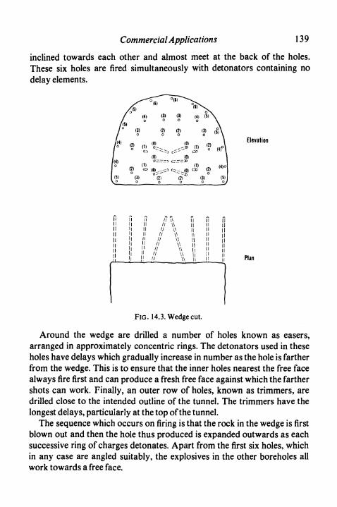
Commercial Applications 139
inclined towards each other and almost meet at the back of the holes.These six holes are fired simultaneously with detonators containing nodelay elements.
Elevation
I lI lIlI lI lI l
I l I lI l I ll ! IlI l I lI l I lI l I lI "I IlH !!
// \\ Il Il// \\ I! II// \\ Ii H// \\ 11 H// \\ Il Il// \\ l| Il
// \\ 1 1 i i// \\ || H// \\ i i n
Il
l!I lI lI i Plan
FIG. 14.3. Wedge cut.
Around the wedge are drilled a number of holes known as easers,arranged in approximately concentric rings. The detonators used in theseholes have delays which gradually increase in number as the hole is fartherfrom the wedge. This is to ensure that the inner holes nearest the free facealways fire first and can produce a fresh free face against which the farthershots can work. Finally, an outer row of holes, known as trimmers, aredrilled close to the intended outline of the tunnel. The trimmers have thelongest delays, particularly at the top of the tunnel.
The sequence which occurs on firing is that the rock in the wedge is firstblown out and then the hole thus produced is expanded outwards as eachsuccessive ring of charges detonates. Apart from the first six holes, whichin any case are angled suitably, the explosives in the other boreholes allwork towards a free face.
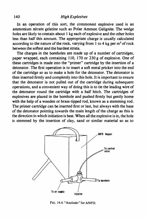
140 High Explosives
In an operation of this sort, the commonest explosive used is anammonium nitrate gelatine such as Polar Ammon Gelignite. The wedgeholes are likely to contain about 1 kg each of explosive and the other holesless than half this amount. The appropriate charge is usually calculatedaccording to the nature of the rock, varying from 1 to 4 kg per m3 of rockbetween the softest and the hardest strata.
The charges in the boreholes are made up of a number of cartridges,paper wrapped, each containing 110, 170 or 230 g of explosive. One ofthese cartridges is made into the "primer" cartridge by the insertion of adetonator. The first operation is to insert a soft metal pricker into the endof the cartridge so as to make a hole for the detonator. The detonator isthen inserted firmly and completely into this hole. It is important to ensurethat the detonator is not pulled out of the cartridge during subsequentoperations, and a convenient way of doing this is to tie the leading wire ofthe detonator round the cartridge with a half hitch. The cartridges ofexplosives are placed in the borehole and pushed firmly but gently homewith the help of a wooden or brass-tipped rod, known as a stemming rod.The primer cartridge can be inserted first or last, but always with the baseof the detonator pointing towards the main length of the charge as this isthe direction in which initiation is best. When all the explosive is in, the holeis stemmed by the insertion of clay, sand or similar material so as to
ANFO Hopper
To borehole
To air supplyInjector
FIG. 14.4. "Anoloder" for ANFO.
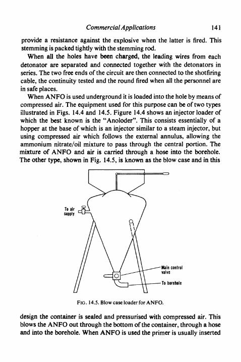
Commercial Applications 141
provide a resistance against the explosive when the latter is fired. Thisstemming is packed tightly with the stemming rod.
When all the holes have been charged, the leading wires from eachdetonator are separated and connected together with the detonators inseries. The two free ends of the circuit are then connected to the shotfiringcable, the continuity tested and the round fired when all the personnel arein safe places.
When ANFO is used underground it is loaded into the hole by means ofcompressed air. The equipment used for this purpose can be of two typesillustrated in Figs. 14.4 and 14.5. Figure 14.4 shows an injector loader ofwhich the best known is the "Anoloder". This consists essentially of ahopper at the base of which is an injector similar to a steam injector, butusing compressed air which follows the external annulus, allowing theammonium nitrate/oil mixture to pass through the central portion. Themixture of ANFO and air is carried through a hose into the borehole.The other type, shown in Fig. 14.5, is known as the blow case and in this
To borehole
FiG. 14.5. Blow case loader for ANFO.
design the container is sealed and pressurised with compressed air. Thisblows the ANFO out through the bottom of the container, through a hoseand into the borehole. When ANFO is used the primer is usually inserted
142 High Explosives
last to allow time for dispersal of any static electrical charges caused by theloading of the hole.
Coal Mining
In order to describe the uses of explosives in coal mining, it is firstnecessary to give a brief outline of the method of mining usually adopted inthe British Isles. This is known as the long wall system.
Before mining commences, shafts are driven from the surface to therequired depth. At least two shafts are required for ventilation to bepossible. From these shafts, tunnels called stone drifts are made, roughlyhorizontally, to the coal seams. The seams may be 1 m or more thick andare usually inclined at an angle to the horizontal.
The actual work of getting coal is at a long straight face of 100 to 200 min length. At each end of this face is a road which is used for conveyingcoal and materials and also for ventilation. The mining process consists ofextracting the coal along the whole length of the face to give a regular dailyadvance. The first stage in extraction is known as undercutting andconsists of cutting a 10 or 12 cm slot to a depth of about 1-5 m. Thiscreates a free face to which the explosives can work. Shotholes are drillednear to the roof level and filled with the explosive and fired. This breaks thecoal down so that it can be loaded onto conveyors which pass along theface to the road. In mechanised mines this whole operation of obtainingcoal is done by machine.
As the face advances, the two roads must be similarly brought forward.Indeed, with mechanised mining, there is at each end of the face a "stablehole" somewhat in advance of the face, so that the machinery can bepositioned between the cuts. Further, in many pits the thickness of the coalmay not be as high as that of the roads, namely, 3 m or so, so that theroads are enlarged as they advance by a process known as ripping.
It must be remembered that methane can be liberated in a coal mine, notonly in the coal itself, but in the nearby stone. It is therefore necessary touse permitted explosives, both in and near a seam of coal. Further, beforeany shot is fired in a coal mine, tests are made for the presence of methanein the air by means of a safety lamp. This safety lamp is the well-knownDavy lamp and an experienced operator can judge the presence ofmethane in the air from the appearance of the flame. Tests are made

Commercial Applications 143
particularly near the roof where methane can accumulate, being lighterthan air. As a precaution against coal dust explosions, the neighbourhoodin the mine is sprinkled liberally with limestone dust which has theproperty of suppressing these explosions.
Explosives are used in coal mines for a wide variety of purposes. Forexample, in the initial sinking of shafts Pl explosives of the gelatine typeare frequently employed. In making the roadways, similar explosives canbe used following the principles described above in tunnelling. The otherplace in coal mines where explosives are fired in stone is in the process ofripping. This in principle is a simple application to bring down stone abovean existing opening. The particular situation in the mine is, however,unusually dangerous and high concentrations of methane are liable tooccur in this vicinity. At the same time, for speed of operation the use ofmillisecond delay detonators is desirable. As the bottom of the rock isunsupported, separation of the rock is liable to occur, either beforeshotfiring or between the succession of shots. These small partings, knownas breaks, can contain methane and then give rise to exceptional hazardsin firing. To meet this situation, the P4 class of explosives has beenintroduced into Britain. These are specially tested for safety when fired inthe presence of breaks containing methane/air mixtures (see p. 86).
Explosives are fired in coal on the face, in the stable holes andsometimes in the making of roads. The commonest practice, as statedabove, is to undercut the coal mechanically. Often a single row of holeswith a permitted P3 explosive is then sufficient to bring down the coal.Powder explosives are most commonly used for this purpose, water-proofed when necessary.
The process of undercutting is time consuming and also requiresmachinery in a congested part of the mine. It is also one which producesa large amount of dust and adds to ventilation difficulties. It is there-fore natural that means have been sought of avoiding undercutting.Historically, the first was the use of pulsed infusion shotfiring, illustrated inFig. 14.6. A special explosive (see p. 89) which will fire when subjected to ahigh pressure of water is placed at the back of the borehole. In the front ofthe borehole is placed a seal to which a water infusion tube is connected.Water is pumped through this tube until it is at the desired pressure and thewhole of the borehole full of water. When the explosive is fired it is in factsurrounded by water and this considerably reduces the risk of gas ignitionand also the amount of dust and fume set free.

144 High Explosives
mmmmmmWater infusion tubes
To firing cable
FIG. 14.6. Pulsed infusion round.
An even simpler means of avoiding undercutting is now being pursued,which introduces also the advantage of allowing short delay detonators tobe employed. In solid coal there is no danger of breaks as in the situationconsidered above in ripping, but there is the possibility that the firstexplosive fired may cause the end of the boreholes of later shots to bebroken, so exposing the explosive. A new class of explosive, known as P5,has been designed with the object of avoiding ignitions under thesecircumstances (see p. 87). This is particularly valuable in stable holes usedin mechanical methods of mining. A wedge cut, or similar cut, as used intunnelling is employed to produce a free face with zero delay detonators.Holes on each side are then fired with longer delay periods and the stablehole can then be cut with a single round of shotfiring. For reasons of safety,the longest delay period allowed is usually 100 or 200 ms so that there canbe no time for appreciable release of methane from pockets of gas. Also thenumber of shots is, in practice, limited to twelve, as this is currently thecapacity of the most powerful exploder which can be guaranteed to be safefor use in gassy mines.
The policy of the National Coal Board is to increase mechanisation inthe mines for reasons both of safety and economy in personnel. Thisprocess has had considerable success on long wall faces and the majorityof these are now worked mechanically. On a few faces complete remotelyoperated mining is possible at present. The process of mechanisation will

Commercial Applications 145
no doubt extend to other parts of the mine, but here the rewards are lessand the convenience and simplicity of explosives ensure that they are likelyto continue in use for many years.
Other Mines
In Britain mining is carried out, apart from coal mines, for anhydriteand gypsum, for iron ore, for non-ferrous ores and for salt. A commonmethod used in this type of mining is known as pillar and stall working,illustrated in Fig. 14.7. The ore, or rock, which is usually in thick seams, isextracted over the whole area of the field, but leaving pillars which supportthe strata above and prevent the roof from falling in. The area occupied by
Unworked coal
FacePropped roof
Ripping
Collapsed roof inworked-out sectionRoad
(a) Long-wall working
(b) Pillar and stall working
FIG. 14.7. Two methods of mining.
Unworked ore
Road

146 High Explosives
the pillars may be as much as a quarter of the whole area of the mine.When a particular mine is worked out it is possible to extract the pillarsand allow the upper strata to subside.
The method of mining is somewhat like driving two sets of tunnels atright angles through the strata. Most mines of this type do not present anyhazard from methane and therefore non-permitted explosives can be used.The selection of powder or gelatine type of explosive depends on the natureof the rock and particularly on the wetness of the mine.
As Britain is relatively poor in mineral deposits, this type of mining isless important here than in other countries of the world. The gold mines inSouth Africa, metal mines in the U.S.A., Canada and Sweden all useconsiderable amounts of explosive. In such mines the methods of workingare often appreciably different from those described above and adapted tovery large-scale production.
Quarrying
The process of quarrying is used to obtain road metal, rock for civilengineering purposes, limestone for steel making and is analogous toobtaining coal from opencast sites where the coal is at or near the surfaceof the ground. The methods used in quarrying can differ considerably indetail concerning the application of explosives, but the commonest isillustrated in Fig. 14.8. A quarry is worked as a series of benches, the
FIG. 14.8. Benching method of quarrying.
Commercial Applications 14 7
height of each being conveniently 15 or 18 m. The width of each bench issufficient to allow access to loaders and lorries, so that each bench can beused as an entity.
To bring down the rock a series of holes is drilled from the surface downto the depth of the bench, or 0-3 to 0-6 m greater. If the bench is 18 mhigh, the holes can conveniently be 10 cm in diameter, 3-5 m back fromthe existing face and 3-5 m apart. They may be drilled either vertically, orat an angle of 70 to 80°. A row of such holes is fired at a time and the effectshould be that the rock in front of them should slump into a heap ofboulders of a size suitable for loading and crushing.
As the major expense in this operation is the drilling of the holes, it isusual to space them as far apart as possible and this is best achieved by theuse of the strongest explosives. Under these conditions 9 tonnes of rockcan usually be broken per kg of explosive. The amount of explosive tobe charged in the drill holes is calculated from a ratio such as this. In theexample quoted, each borehole will contain approximately 70 kg ofexplosive. If the conditions are at all wet, a gelatinous explosive is used,particularly at the foot of the hole. Under dry conditions, or in the upperpart of the hole, where the work to be done by the explosive is less, weakerexplosives can be used and ANFO is often suitable. The holes are charged,either by lowering cartridges downwards, or else by pouring in free-flowing explosive, such as ANFO.
The charges can be fired with electric detonators, but the commonermethod is to use detonating fuse, usually known in Great Britain asCordtex. This is capable of initiating gelatine explosives, such as OpencastGelignite, without the extra use of a detonator. It is also a convenientmethod of connecting boreholes together. The method of application isshown in Fig. 14.9 A trunk line of Cordtex lies on the bench of the quarryand from this branch lines extend down the holes to the bottom.Frequently with large holes two lines of Cordtex are employed to makecertain of initiation under all conditions, because in a large quarry blast asingle failure from any cause can be extremely expensive. It is anadvantage to arrange for the holes to be fired in succession by a series ofshort delays and this is done by inserting in the trunk line special delayconnectors which give time lags of 15 ms. When the shot is fired, most ofthe noise comes not from the main charge of explosive itself, but from theCordtex on the surface of the quarry. This noise can, however, beconsiderably reduced by covering the Cordtex with sand or stone dust.

148 High Explosives
Toe of overburden
Cordtex linkingline
Detonating relays^between each line , ,
• Detonating relays betweenadjacent holes
FIG. 14.9. Quarrying with Cordtex and detonating relays.
Removal of rock is required for many civil engineering purposes, anduses explosives in a manner similar to quarrying. An interesting techniqueis that known as pre-splitting. In this holes are drilled on the line of theproposed edge of the roadway, or cutting. These are filled with blastingexplosives in relatively low charge, but the holes are drilled close together.When the explosive is fired a crack is formed along the line of the holes, butwith little or no damage to surrounding rock. Subsequently the rock isremoved by normal blasting and breaks away cleanly at the line of holes.This in suitable cases leads to a well-formed face of solid rock which can befinished by the minimum of concrete or other preparation.
No matter how well a blasting operation is carried out, there is liable tobe some amount of rock left in the form of boulders too large to be handledby normal equipment. This is an inevitable result of lack of uniformity ofrock. These boulders are broken down in size by a process known assecondary blasting. The usual method is to drill holes into the boulders,load them with explosives and fire. In certain cases the explosive can beplaced on the surface of the boulder, covered liberally with clay or othermaterial, and then fired. A cheap and effective way of detonating suchcharges is with safety fuse and detonators, the lengths of the fuse beingarranged so that the shotfirer has ample time to get to safety. TheRegulations do not allow more than six ends of safety fuse to be lit at onetime by a shotfirer. Instead, the ends are connected to igniter cord (see p.131). The shotfirer then has to light only the end of the igniter cord beforeretiring to a prepared position.

Commercial Applications 149
Seismic Prospecting
Sound waves in the ground are reflected at the boundaries betweenstrata in the same way as sound waves are reflected from walls ofbuildings, etc. In seismic prospecting use is made of this by generating awave with a charge of explosive and observing the reflections by means ofgeophones placed at suitable positions. This enables a geological map ofthe substrata to be drawn and indicates to the explorer the sites most likelyto contain oil. This prospecting can be carried out either on land or at sea.
Explosive Geophoncs- Surface
Undergroundstratum
FIG . 14.10. Seismic prospecting by reflection method.
Figure 14.10 illustrates the method of seismic prospecting on land bywhat is known as reflection shooting. A hole usually 10 to 12cm indiameter is drilled to a depth of 15 to 30m. The charge of explosive islikely to be 5 to 12-5 kg and the stemming used is usually water. As theexplosive must fire under a depth of water which may exceed 45 m, specialvarieties of gelatines are employed (see p. 53). Alternatively, a powderexplosive can be sealed into pressure-resistant metal containers. Specialdetonators are also employed, not only to withstand the possible head ofwater, but also to have a specially short bursting time (see p. 113).
Seismic prospecting is also carried out at sea, the explosive charge beingin a metal container and the geophones stretched along a cable from thestern of a ship. Either one or two boats may be used; charges are fired andrecords taken at regular intervals while the vessels are steaming. Theexplosive must be fired near the surface of the water, otherwise, as noted inChapter 2, a bubble is formed which oscillates and passes into the water aseries of shocks; the seismographic recordings then obtained areunsatisfactory for analysis. When the explosive is fired within 1 -2 or 1 -5 m

150 High Explosives
of the surface, the bubble is not formed, as the gases are immediatelydischarged into the atmosphere. In recent years prospecting for oil in theNorth Sea has been on a large scale and several thousand tonnes ofexplosive per annum have been used.
Miscellaneous Uses
There are many miscellaneous applications of explosives which may bementioned but which do not merit individual description. Such uses arethose in agriculture, in the preparation of ditches, the diversion of streams,removal of tree stumps, and the breaking up of subsoil. Demolition of oldbuildings and chimneys is readily carried out. Underwater wrecks mayalso be broken up for disposal by special application of explosive charges.
Of special interest is the civilian application of shaped chargesdeveloped initially for military purposes (see Chapter 15, p. 158). Onesuch application is the blast furnace tapper illustrated in Fig. 14.11. In this
Plastic caseMetal cone Explosive Detonator
FIG .14.11. Shaped charge for tapping blast furnaces.
the conical charge is used to penetrate a clay plug which seals the outlet ofa blast furnace, and affords a quicker and safer method than the normaloxygen lance. Wedge-shaped charges have been developed for the cuttingof submarine cables for lifting for repair.
In recent years much attention has been paid to the use of explosives forthe shaping and working of metals. Figure 14.12 illustrates a simpleapplication of the process for forming a dished end of a vessel. A flat metalblank is placed over a suitable mould and the space between themevacuated. Above the blank is water and in this a suitable explosive chargeis fired. The metal takes the form of the mould with little or no spring-backand usually does not require further treatment. The process is particularly

Commercial Applications 151
. Water
— Metal sheet
FIG .14.12. Forming metal with explosive.
suited to the preparation of small numbers of complicated shapes, as noexpensive equipment is required. It is therefore of particular interest in theproduction of prototypes for aircraft, missiles, etc.
An application of increasing importance is in the cladding of metals. Inthis a layer of explosive is used to project the cladding on to the base metalat such a speed that the two become firmly welded together. Fig. 14.13shows one technique for small items where the cladding is at an angle to
Explosive
Gladding
FIG. 14.13. Cladding metal with the use of explosive.
the base, which is firmly supported. The best results are however obtainedby supporting the cladding parallel to the base plate and a short distancefrom it. The explosive used must have a suitable velocity of detonation,somewhat lower than the velocity of sound in the metals. The cladding andthe base become welded with a wavy interface; the durability of the bond issuch that the clad can readily be rolled or fabricated. Many combinationshave been successfully made, of which the most note-worthy is probablytitanium clad steel.
Many other applications of explosives could be described, but the ones
152 High Explosives
mentioned above are those of the greatest magnitude. Often thoseapplications which use the smallest amounts of explosives are technicallythe most interesting, as they demonstrate best how accurately mechanicaleffects can be produced in minute fractions of a second.
References
HINO , K., Theory and Practice of Blasting. Nippon Kayaku Co., Japan, 1959.LANGEFORS, U., and KIHLSTROM, B., Modern Techniques of Rock Blasting. Wiley,
London, 1963.McADAM, R., and WESTWATER, R., Mining Explosives. Oliver & Boyd, London, 1958.SINCLAIR,!., Winning Coal. Pitman, London, 1960.

CHAPTER 15
Military Applications
THE first offensive weapons used by man were probably stones, andsimilarly the first objects thrown when mortars were developed were solid,usually spherical, balls of stone or iron. With the development ofexplosives it was soon realised that it would be more effective to use ahollow missile filled with explosive, designed to burst in the middle of theenemy. Gunpowder was originally used as filling, but has now beencompletely superseded by high explosives.
It is convenient to differentiate between three broad classes of use ofhigh explosive fillings.
(a) The explosive is designed to rupture its container into fragmentswhich are projected as shrapnel against enemy personnel.
(b) The explosive is used to produce a blast effect against enemybuildings and equipment.
(c) The explosive is used to penetrate targets such as armouredvehicles.
For the first purpose relatively small amounts of explosive are used and thenature of the explosive is of secondary importance. For the other purposes,however, larger proportions are necessary and for maximum effect themost powerful explosives are required.
Grenades
The modern equivalent of a stone thrown by hand is the hand grenade,of which the best-known form is the Mills bomb illustrateddiagrammatically in Fig. 15.1. The steel shell is thinned along crossinglines, so that on explosion it is broken into fragments of predeterminedsize. When the grenade is thrown the lever is released and allows the
153
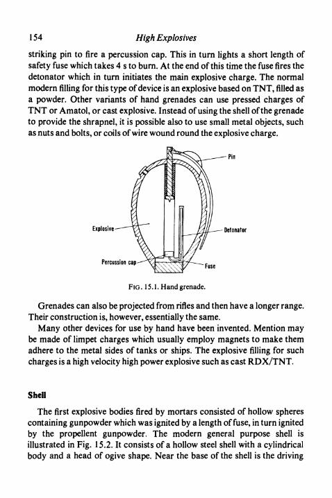
154 High Explosives
striking pin to fire a percussion cap. This in turn lights a short length ofsafety fuse which takes 4 s to burn. At the end of this time the fuse fires thedetonator which in turn initiates the main explosive charge. The normalmodern filling for this type of device is an explosive based on TNT, filled asa powder. Other variants of hand grenades can use pressed charges ofTNT or Amatol, or cast explosive. Instead of using the shell of the grenadeto provide the shrapnel, it is possible also to use small metal objects, suchas nuts and bolts, or coils of wire wound round the explosive charge.
Explosive Detonator
Percussion cap Fuse
FIG .15.1. Hand grenade.
Grenades can also be projected from rifles and then have a longer range.Their construction is, however, essentially the same.
Many other devices for use by hand have been invented. Mention maybe made of limpet charges which usually employ magnets to make themadhere to the metal sides of tanks or ships. The explosive filling for suchcharges is a high velocity high power explosive such as cast RDX/TNT.
Shell
The first explosive bodies fired by mortars consisted of hollow spherescontaining gunpowder which was ignited by a length of fuse, in turn ignitedby the propellent gunpowder. The modern general purpose shell isillustrated in Fig. 15.2. It consists of a hollow steel shell with a cylindricalbody and a head of ogive shape. Near the base of the shell is the driving
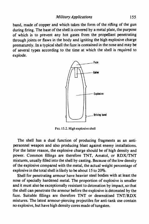
Military Applications 155
band, made of copper and which takes the form of the rifling of the gunduring firing. The base of the shell is covered by a metal plate, the purposeof which is to prevent any hot gases from the propellant penetratingthrough joints or flaws in the body and igniting the high explosive chargeprematurely. In a typical shell the fuze is contained in the nose and may beof several types according to the time at which the shell is required toexplode.
Fuze
Gaine
- Explosive
. Driving band
FIG. 15.2. High explosive shell
The shell has a dual function of producing fragments as an anti-personnel weapon and also producing blast against enemy installations.For the latter reason, the explosive charge should be of high density andpower. Common fillings are therefore TNT, Amatol, or RDX/TNTmixtures, usually filled into the shell by casting. Because of the low densityof the explosive compared with the metal, the actual weight percentage ofexplosive in the total shell is likely to be about 15 to 20%.
Shell for penetrating armour have heavier steel bodies with at least thenose of specially hardened metal. The proportion of explosive is smallerand it must also be exceptionally resistant to detonation by impact, so thatthe shell can penetrate the armour before the explosive is detonated by thefuze. Suitable fillings are therefore TNT or desensitised TNT/RDXmixtures. The latest armour-piercing projectiles for anti-tank use containno explosive, but have high density cores made of tungsten.

156 High Explosives
Shrapnel
Driving band
Explosive charge
FIG. 15.3. Shrapnel shell.
The well-known shrapnel shell, used for anti-personnel purposes, is ofquite different construction and is illustrated in Fig. 15.3. The base andsides of the shell are of heavy construction, but the nose is relatively weakand contains a fuze which is easily ejected by the explosive charge from thebody of the shell. Immediately behind the fuze is a filling of metal shrapnel,often bonded relatively weakly with resin. The explosive charge is at thebase of the shell behind the shrapnel. After a time of flight determined bythe setting of the fuze, the explosive charge detonates and projects theshrapnel forward out of the shell as an expanding cone. In modern warfarethe shrapnel shell is becoming of limited importance.
Bombs
Bombs carried by aircraft can be made of lighter construction thanshell, because they do not have to resist the acceleration of firing from agun. The general construction is shown in Fig. 15.4, but differences existaccording to the detailed purpose for which the bomb is to be used.
Anti-personnel bombs have a relatively heavy casing containing anexplosive such as Amatol, sufficiently strong to break the casing intofragments on impact. Bombs intended to produce a blast effect againstbuildings have a lighter casing and are usually filled with an explosivecontaining aluminium to increase the blast effect. Armour-piercing bombs

Military Applications 157
FIG. 15.4. Aircraft bomb.
for use against warships resemble armour-piercing shell in their type ofconstruction and have heavy bodies with smaller high explosive charge. Inthe proper functioning of all these bombs, design of the fuze is ofparamount importance.
Torpedoes
The explosive charge in a torpedo is carried in the nose, the rearcompartments containing fuel and motor, together with the controlequipment. As the torpedo must penetrate the ship to give the best effects,the nose is of heavy steel construction and the fuze operates with a delay.The high explosive charge must therefore be of maximum density andpower. As the torpedo operates under water, the shock wave isconsiderable and advantage can well be taken of the increased energygiven to explosives by the addition of aluminium. A common filling istherefore Torpex which consists of a mixture of RDX, TNT andaluminium and which has a high density, high power and high velocity ofdetonation. Maximum density is attained by filling the head of the torpedoby a carefully controlled casting process.
Depth charges for use against submarines are similar in principle to

158 High Explosives
bombs, but have their effect mainly by the shock wave produced underwater. They therefore have relatively light shells containing a denseexplosive of high velocity of detonation and high power. Cast RDX/TNTmixtures, with or without aluminium, are suitable for this purpose.
All the explosives used for military purposes are in general veryinsensitive and except in the smallest hand grenades a gaine or booster isused to ensure proper initiation. Such gaines are usually made bycompressed pellets of tetryl inserted as a column into a metal tube insidethe explosive charge.
Shaped Charges
Increased protection to military personnel, particularly in thedevelopment of armour-plated vehicles, has led to a rapid growth inimportance of weapons using shaped charges of explosive. The effects ofshaping the explosive itself were observed independently by Munroe and
Explosive -
Detonation front :
Metal liner
(1) Before flrino
(2) During firing
(3) During firing
(4) After firing
FIG. 15.5. Shaped charge-formation of jet and slug.

Military Applications 159
Neumann, but the development of practical charges with linings was dueto a large number of workers.
If a conical depression is made in the end of a column of explosive, theshock wave is concentrated along the axis of the charge, which then hasincreased local penetration of metal or stone. A different and much morepronounced effect is achieved if the cone is lined with metal, as this forms ajet followed by a slug; the jet is projected forward at high velocity and canpenetrate to great depths, giving a long, almost cylindrical hole. The stagesof formation of the jet are illustrated in Fig. 15.5. In a sense, the cone isturned inside-out and collapsed, a process only complete some distance infront of the charge, so that a stand-off distance of one or more chargediameters is needed to ensure maximum penetration. A diagrammaticpractical design of a shaped charge is shown in Fig. 14.11 (p. 150), wherethe explosive is shaped to give maximum economy, and the case providesan automatic stand-off.
The penetrating power of a shaped charge is approximatelyproportional to the cube of its diameter, but also very dependent onmaintenance of exact axial symmetry during construction. It is alsoproportional to the detonation pressure of the explosive used, so thatsuitable fillings are cast Pentolite or RDX/TNT. Well-known applicationsof shaped charges are in the British PIAT and American bazooka.
A recent alternative to shaped charges is known as the squashheadprojectile. As the name implies, this contains a plastic explosive whichspreads on impact so as to make contact with the largest possible area ofthe tank before detonating. When the explosive detonates, reflection of theshock wave causes a scab of metal to be displaced from the inside surfaceof the armour plate (see p. 135). The effect inside the tank can thereforebe greater than is the case with a shaped charge which may do little morethan penetrate the armour. The amount of scabbing is approximatelyproportional to the area of contact of the explosive at the moment ofdetonation.
References
COOK , M. A., The Science of High Explosives. Reinhold, New York, 1958.OGORKIEWICZ , R. M., Engineering, 21 July 1961, p. 78.OHART, Maj. T. C., Elements of Ammunition. Chapman & Hall, London, 1946.


Part IV. Deflagrating and PropellentExplosives

Introduction
GUNPOWDER was first employed as a propellent explosive in guns,although later it was also employed for blasting. In neither case, however,does it detonate in the same way as the blasting explosives described inPart I, or the initiating explosives described in Part II of this book.
As a gun and rifle propellant, gunpowder had serious disadvantages. Itwas rather unpredictable in use, extremely dirty and caused considerablefouling of gun barrels. It also emitted an excessive amount of smoke andflash which immediately disclosed the position of the gun to the enemy.When Nobel and Abel invented ballistite and cordite respectively, many ofthese disadvantages were immediately overcome. Gelatinised nitro-cellulose was soon found in France to have similar advantages. Gun-powder is no longer used as a propellent explosive.
Gunpowder was supplied in pellet form as a propellant and thesubstitutes were similarly manufactured. They were therefore calledpowders. Subsequent developments have led to the provision of propellentexplosives in special and often massive form. Nevertheless, the termpowder is still retained for their nomenclature, and the individual unit ofthe charge, no matter how large, is still called a grain.
Although these explosives do not detonate under conditions of practicaluse, this does not mean that they are incapable of detonation. Thepossibility cannot be ignored when large quantities are being handled.
163

CHAPTER 16
Blackpowder
Manufacture
The raw materials potassium nitrate, charcoal and sulphur are firstbrought to a fine condition. Potassium nitrate must be ground by itself, butthe charcoal and sulphur may be ground together or separately accordingto individual requirements. This grinding is frequently carried out in steelball mills. The products are then sieved to remove any oversize orextraneous matter.
Appropriate quantities of the raw materials are added to a mill forintimate mixing and grinding. The mills used are of edge runner type inwhich a cast iron pan carries the blackpowder and the edge runners arelarge cylindrical wheels of steel, each weighing about 5-5 tonnes. Thesewheels are suspended with a clearance of about 6 mm from the bed toreduce hazard, as contact with the wheels is solely with blackpowder andfriction between iron and steel is avoided. The charge of a blackpowdermill is about 125 kg. During mixing the wheels are rotated and roll on theblackpowder, whilst ploughs carry the material spread sideways by thewheels back into their path. Throughout the milling operation water isadded to maintain a moisture content of 1 to 1-5%; this reduces the dangerand also increases efficiency by assisting the incorporation of potassiumnitrate into the charcoal. The milling process takes from one to sevenhours according to the nature of the product required.
The mill cake taken from the mill is broken by passing between toothedgunmetal rolls to produce powder, which is then pressed between brassplates in a hydraulic press to a pressure of about 7 MPa, depending on theproperties finally required. The purpose of the pressing is twofold. On theone hand it increases the intimacy of contact of the ingredients andimproves the burning properties of the powder. On the other hand, it
164

Blackpowder 165
increases the physical strength of the powder and reduces breakdown ofthe finished grain during transport and use.
The press cake is broken by passing it between gunmetal rolls, usuallytoothed. The coarse product thus produced is subjected to the corningoperation. This consists of passing the material through a series of metalrolls which progressively break down the grain into smaller size, andsieving by shaker sieves. The required sieve size is extracted for furtherprocessing, coarse material returned for regrinding and fine material forreprocessing.
The sieved grains are glazed or polished by rotating in a drum for aperiod of about 6 h, frequently with the addition of a small amount ofgraphite to give a surface polish. This glazing process gives a roundedgrain which is free flowing and which has increased resistance to moisture.The product is finally sieved to remove any dust.
To ensure adequacy of manufacture, blackpowder is subjected to anumber of tests of which the following are probably the most important.The burning speed of the powder is determined, usually by making up alength of lead fuse and determining its burning speed. The rate of burningunder confinement is measured in a "prover" which is a closed vessel witha piezo-electric pressure gauge and cathode ray oscillograph. The trace onthe oscillograph gives the maximum pressure reached and also the rate ofcombustion to this stage.
Most blackpowders contain 75% of potassium nitrate, 15% of charcoaland 10% of sulphur. For safety fuse, however, blackpowders are madewith reduced amounts of potassium nitrate. Also manufactured aresulphurless powders, containing approximately 70% of potassium nitratewith 30% of charcoal. These sulphurless powders are used for ignitionpurposes where sulphur could cause corrosion of metallic components.
Properties of Blackpowder
The density of blackpowder is usually about 1-7, but depends on thecompression during the pressing process. There is a wide range of sizes,varying from about 12 mm diameter to material which passes a 150 meshsieve. Blackpowder is ignited readily at a temperature of about 30O0C for

166 High Explosives
the normal product, or 34O0C for the sulphurless meal. It is hygroscopic athumidities exceeding 90% and then rapidly ceases to burn.
The properties of blackpowder depend considerably on the charcoalused. Soft woods freed from bark give the best results. Alderwood anddogwood are best, but the cheaper birch and beech are frequently used forordinary purposes. In any case, it is important that the woods should becarbonised to the correct extent and this depends on the nature of thewood. In the case of alder, the optimum carbon content is 74%, whereaswith birch a figure of 82% gives the best results. In general, if the carboncontent is too low a readily ignited blackpowder is obtained but it has slowburning properties. It is also difficult to manufacture. If the carbon contentis too high the material is easy to grind and milling is rapid, but the finalblackpowder may be difficult to ignite and irregular in burning.
The burning speed of the powder in the lead fuse test can also be variedby changing the potassium nitrate content. The maximum burning speed isusually observed at a content of rather less than 70% of potassium nitrate.
It was shown by Vieille that the rate of burning, R, of blackpowderdepends exponentially on the pressure,p, by the following equation:
R=apn
a and n being constants.
Mechanism of Combustion of Blackpowder
The mechanism of combustion of blackpowder is extremely complexand only an outline can be given here. It will be convenient to consider firstthe initial chemical reactions in ignition, then the reactions which occurduring the main combustion and finally the nature of the products.
Hofmann and Blackwood and Bowden have studied the chemicalchanges which occur at temperatures approaching 30O0C, which is thetemperature of thermal ignition of blackpowder. That the process involvesgases is shown by the proof by Blackwood and Bowden that ignition canoccur at hot spots at temperatures as low as 13O0C, provided that the localpressure is at least 150 atm. An important part in the reaction is played bya constituent of charcoal which can be extracted with acetone and shownto contain carbon, hydrogen and oxygen. Sulphur can react with thissubstance at temperatures as low as 15O0C to produce hydrogen sulphide,

Blackpowder 167
which in turn can react with potassium nitrate at about 28O0C to givepotassium sulphate. Also at about 28O0C the organic constituent ofcharcoal can react with potassium nitrate with the liberation of nitrogendioxide. The direct reaction of potassium nitrate and sulphur to givepotassium sulphate and oxides of nitrogen commences at about 25O0C,but becomes rapid only above the melting point of potassium nitrate,33O0C.
At temperatures below 30O0C, the evolution of hydrogen sulphide issufficient to reduce the nitrogen dioxide also produced, with the formationof sulphur and nitric oxide. As the temperature is raised, however, theevolution of nitrogen dioxide increases until there is excess which can reactwith sulphur to give sulphur dioxide and nitrogen. This sulphur dioxide canthen react with potassium nitrate to give potassium sulphate in a stronglyexothermic reaction. The heat produced in this reaction leads to furthertemperature rise and thus to mass ignition of the blackpowder.
The main process of combustion of blackpowder was studiedexhaustively by Nobel and Abel and by Berthelot. These experimentalresults were examined in much greater detail by Debus, who has provideda self-consistent account of the chemical reactions involved. Debusconsiders that the overall reaction can be divided into two distinct stages:(a) a rapid oxidation process and (b) a slower reduction process.
The oxidation process is responsible for the actual explosion. Whilst it isno doubt complex, it can be simplified to the following overall equation:
1OKNO3 + 8C + 3S -*2K2CO3 + 3K2SO4 + 6CO2 + 5N2
As the initial composition of blackpowder contains, for each 10 moleculesof potassium nitrate, 14 molecules of carbon and 4 molecules of sulphur,this equation does not account for 6 molecules of carbon and 1 molecule ofsulphur.
The excess carbon and sulphur take part in slower reduction reactionswhich are as follows:
4K2CO3 + 7S-> K2SO4 + 3K2S2 + 4CO2
4K2SO4 + 1C ->2K2CO3 + 2K2S2 + 5CO2
As the reduction is a slow process, it is not necessarily complete when theblackpowder has done its work. The reduction reactions are endothermicand lower the total heat evolution. On the other hand they increase theamount of gas evolved. Hofmann considers that these equations represent

168 High Explosives
only the overall reactions and that the actual paths are more complicated,involving the intermediate production of potassium monosulphide and ofvarious gaseous products, including oxides of nitrogen.
As the reduction stage of the reaction does not necessarily go tocompletion the reaction products depend to some extent on the conditionsof firing. In all cases, however, the chief products appear to be potassiumcarbonate, potassium sulphate, potassium disulphide, carbon dioxide,nitrogen and carbon monoxide, the last named arising either from theoxygen in the charcoal, or from side reactions. Side reactions give the by-products usually observed, namely, hydrogen, hydrogen sulphide,methane, ammonia, water and potassium thiocyanate. In most analysessmall amounts of unburnt powder have also been observed.
CHAPTER 17
Manufacture of Propel/ants
Introduction
Current propellent explosives may be divided into three classes: singlebase, double base and composite; however double base propellants whichcontain picrite are often considered a separate class and called triple base.
Single base propellants are basically nitrocellulose which has been madecolloidal by the action of solvent.
Double base propellants contain nitroglycerine in addition tonitrocellulose and frequently other additives to give special properties.They can be manufactured by three methods and are then known assolvent type, solventless type and cast double base compositions. In thefirst method solvent is employed to ensure completeness of gelation of thenitrocellulose by the nitroglycerine. Such powders are used in small grainsizes. The solventless process gives a dimensionally more stable product asgelatinisation is performed without the aid of solvent. The method cantherefore be employed for making larger grains for burning in smallrockets and in gas-producing devices. Limitations of reasonable presscapacity prevent even this method from being used for making the largestrocket charges. For this purpose the casting process is employed and theproduct is known as cast double base (CDB) composition. This process isgenerally employed only for the manufacture of rocket charges.
The third type of propellent explosive, the composite type, is a morerecent development, the purpose of which is to provide rocket propellantsof increased thrust, compared with the ordinary varieties. Compositepropellants are based on an oxidising solid, commonly a perchlorate,together with an organic binder which both acts as fuel and gives adequatemechanical strength to the mixture. The search for even more energeticcompositions continues, but because of the military importance of the
169

170 High Explosives
results, little has been published. Table 17.1 from Kirk and Othmer givestypical compositions of single and double base propellants.
Single Base Propellants
As single base powders have been developed particularly in the U.S.A.,their method of manufacture may be described as illustrating the principlesinvolved. British practice is similar but often with omission of the"macaroni" pressing stage.
The nitrocellulose is first dehydrated, that is the water present isreplaced by alcohol. This is done by compressing the wet nitrocellulose ina hydraulic press and passing alcohol through the press until the strengthin the block is about 92%. The resulting block of alchohol wetnitrocellulose is broken down to small pieces with toothed rolls.
The incorporating process is carried out in mixing machines of theWerner Pfleiderer type, that is with two heavy horizontal blades in aspecially shaped bowl. Incorporation consists of mixing the alcohol wetnitrocellulose and other ingredients with a solvent, normally ether andalcohol mixture. The amount of solvent used is adjusted so that the finalconsistency is that of a stiff dough.
This dough is transferred to a "blocking" press and there formed by thehelp of hydraulic pressure into solid blocks free from air. The blocks arethen placed in a "macaroni" press, in which they are extruded throughgauzes and dies into a mass of cords similar in appearance to macaroni.These cords are passed to a second block press so that a further block formis produced. These blocks are then placed in the final press, which has a dieplate with dies of the correct size to give the physical dimensions requiredin the finished product. Above this plate is a series of gauzes to strain outany ungelatinised or foreign particles. The strands emerging from thispress may be collected in a number of individual containers and then fedinto a cutting machine. This cutting machine has rotating angled bladeswhich brush the face of a perforated cutter bar. Strands are fed through thecutter bar by rollers geared to the rotating knives so that a constant lengthof cut grain is assured.
In an older cutting process still much used, strands are formed into abunch which is then cut by guillotine.
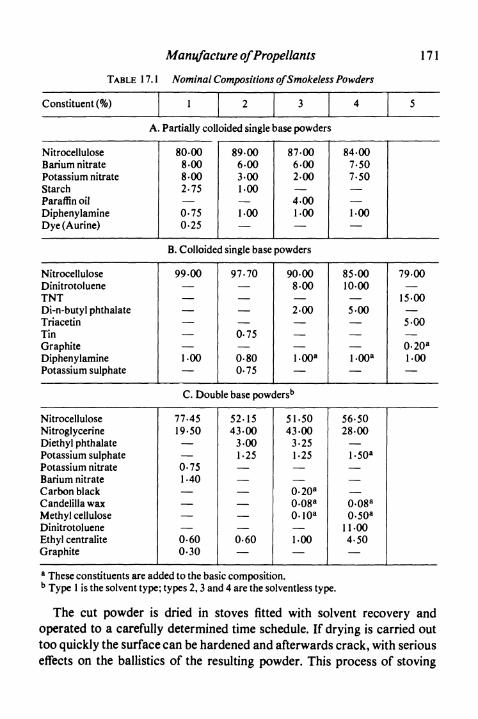
Manufacture ofPropellants
TABLE 17.1 Nominal Compositions of Smokeless Powders
171
Constituent (%) 1 2 3 4 5
A. Partially colloided single base powders
NitrocelluloseBarium nitratePotassium nitrateStarchParaffin oilDiphenylamineDye ( Aurine)
80-008-008-002-75—0-750-25
89-006-003-001-00
—1-00—
87-006-002-00
—4-001-00—
84-007-507-50——1-00—
B. Colloided single base powders
NitrocelluloseDinitrotolueneTNTDi-n-butyl phthalateTriacetinTinGraphiteDiphenylaminePotassium sulphate
99-00———
—
1-00
97-70—
——
0-75
0-800-75
90-008-00—2-00
—
L00a
85-0010-00
—5-00
—
l-00a
79-00—
15-00
5-00—0-20a
1-00
C. Double base powdersb
NitrocelluloseNitroglycerineDiethyl phthalatePotassium sulphatePotassium nitrateBarium nitrateCarbon blackCandelilla waxMethyl celluloseDinitrotolueneEthyl centraliteGraphite
77-4519-50——0-751-40——
——0-600-30
52-1543-00
3-001-25
——
———
—0-60—
51-5043-00
3-251-25—
—0-20a
0-08a
0-10a
—1-00—
56-5028-00
—l-50a
———0-08a
0-50a
11-004-50—
a These constituents are added to the basic composition.b Type 1 is the solvent type; types 2,3 and 4 are the solventless type.
The cut powder is dried in stoves fitted with solvent recovery andoperated to a carefully determined time schedule. If drying is carried outtoo quickly the surface can be hardened and afterwards crack, with seriouseffects on the ballistics of the resulting powder. This process of stoving

172 High Explosives
does not satisfactorily remove all the solvent and the last traces areremoved by steeping in water at carefully controlled temperatures. Thesteeped powder is then dried by hot air.
Adequate ballistics cannot be achieved in single batches of propellants,even with closest control. It is therefore universal practice to take materialfrom a number of batches of manufacture and blend them until correct anduniform ballistics can be ensured.
A common method of obtaining high rates of burning for shotguns,revolvers and pistols is the incorporation of potassium nitrate in the dough,followed by leaching of this potassium nitrate during the steeping process.In this way a product of controlled porosity and therefore controlled rateof burning is obtained. Such powders are also sometimes prepared in flakeform by rolling into sheet and then cutting.
Rifle powders, particularly when porous, can burn so rapidly that theinitial rise of pressure can be faster than necessary. In this case, the grainscan be surface moderated, or given a surface coating of a nitrocellulosegelatiniser, such as dinitrotoluene, dibutylphthalate, or carbamate. Thisprocess is often carried out at the same time as glazing, with a smallamount of graphite, which improves the flow properties of the powder aswell as increasing its loading density.
Double Base Powders—Paste Mixing
In modern practice the use of dry guncotton is avoided for reasons ofsafety and the first stage in the process of manufacture, whether for solventtype or solventless products, is the formation of a paste from wetguncotton. The British methods by which this is done are described byWheeler, Whittaker and Pike. There are in fact two methods which havebeen used. In one a slurry of finely pulped guncotton is made in water andcirculated through a ring main. The concentration of the slurry isdetermined and then a suitable volume is measured in a tank. This is thenpassed, either with the original process water, or with previously usedwater, into a tun dish in which the slurry is sprayed with nitroglycerine.The slurry then passes to a mixing tank in which a stabiliser and chalk areadded and the whole is stirred for a period of not less than 30 min.
Alternatively, the guncotton can be obtained in a water-wet condition in
Manufacture ofPropellants 173
which it contains approximately 30% of water. The water content isdetermined and the appropriate amount of wet guncotton for a batch isweighed out. This is slurried in water in a pre-mix tank and thennitroglycerine is run in with stirring. The product is transferred to a finalmixing tank where it is processed as above.
The mixture is then run on to a sheeting table which is made on the sameprinciple as a paper-making machine, but with the wire replaced for safetyby a suitable cloth filter. The pulp passes over suction tubes and betweenrollers in order to remove as much water as possible, so that the pastewhen stripped from the cloth contains 20-25% of water. It is dried on traysor else in trucks through which air at 5O0C is blown.
Solvent Type Double Base Propellents
Dried paste is weighed into incorporators, usually of the WernerPfleiderer type. To the incorporators are added the appropriate amountsof other ingredients and also solvent which is usually acetone or a mixtureof acetone and water. When mixing is finished a stiff dough is obtained.This is rammed into the cylinder of a hydraulic press at one end of which isa die containing holes of diameter depending on the cord size required. Forcannon powders, for example, cord diameters are large and only a few areextruded. The cut cords are taken to a solvent recovery stove, where theacetone is removed and recovered; the final stoving to remove the lasttraces of acetone is sometimes given at a higher temperature. The powderis blended with extreme care so as to give completely regular performance.
Ball Powder
In the ball powder process, developed by the Western CartridgeCompany, nitrocellulose is agitated with ethyl acetate solvent in aqueoussuspension with emulsifying ingredients. This gives a suspension ofspheres, the size of which can be controlled by the speed of stirring. Thesuspension is heated to distil off the solvent and harden the spheres, whichafter cooling can be impregnated with nitroglycerine and dried. Ifnecessary the spheres can be rolled to decrease the web thickness and timeof burning and they can be graphited according to requirements. The

174 High Explosives
process is particularly applicable to the manufacture of rifle powders, butit is also used in producing grains suitable for the slurry casting process.
Solventless Double Base Propellents
The use of solvent limits the size of grain which can be producedbecause of the difficulty of removing final traces of solvent and thusensuring ballistic stability during storage. The solventless processovercomes this difficulty by attaining gelatinisation of the paste by theeffect of heat and work. The dried paste is first passed repeatedly throughhot rolls to a definite schedule of passes and roll settings. Reworkedmaterial can be blended in at this stage.
The sheets thus produced are cut into discs, or else formed into carpetrolls. The former process involves cutting circular or square portions fromthe sheets so as to fit the extruding press. These are examined for flaws andthen compressed to form a "cheese". The latter process involves cuttingthe sheet into strips which are then rolled into "carpet rolls" of a diametersuitable to fit the cylinder of the extruding press.
The propellant is extruded hydraulically at pressures of 15-35 MPa.The press cylinders are heated and filled with heated discs or carpet rolls.In most modern practice the cylinders can be evacuated to avoid airbubbles in the final propellant. For the larger sizes, the press dies give asingle large cord which is cut to length by a guillotine while still hot. Aftercooling it can be handled in wood-working machinery under suitableconditions to give exact length and for such purposes as slotting or drilling.For smaller sizes of grain, the process is similar to that for the solvent typeproduct, but without the necessity of the solvent recovery stage.
Cast Double Base Propellents
Although the solventless cordite process enables grains of largerdiameter to be made than are possible by the solvent process, it isnevertheless restricted to about 10 cm in diameter, owing to difficulties inmaintaining dimensional stability and to difficulties in construction ofadequate extrusion presses. The problem of producing larger grains of thistype of propellant has been overcome by the introduction of the casting

Manufacture ofPropellants 175
process. This utilises a powder consisting of nitrocellulose andnitroglycerine, with any necessary modifiers, and a casting liquid whichconsists of nitroglycerine with suitable desensitisers. A case is filled withthese ingredients to give an air-free heterogeneous mixture. It is thensubjected to prolonged heating, so that the nitroglycerine swells thenitrocellulose until finally a homogeneous structure results.
In the simpler version of this method, a double based powder of smallsize is made by conventional solvent methods and thoroughly dried. Therequired amount of this powder is then placed in a "beaker" of celluloseacetate or ethyl cellulose and the voids are all filled with desensitisednitroglycerine. The curing process consists of heating to temperatures ofthe order of 8O0C for a prolonged period and on cooling, the massbecomes a gelatinous body similar to cordite or ballistite.
In another version of this process developed in America, the grain andthe nitroglycerine are formed into a slurry which is poured as such into thecasing before curing. This process has been described by Boynton andSchowengerdt. The nitrocellulose is used in the form of a ball powder ingranules which may vary from a few microns to a coarse mesh size. Thenitroglycerine and other liquid ingredients are then placed in a simplemixing pot and the solid ingredients, including the nitrocellulose, added.After stirring for a few minutes the slurry is poured into a case and curedby heat.
It is possible in both the above processes to add oxidisers such asammonium perchlorate so as to give propellants which combine theproperties of the composite propellants and the more conventional doublebase type. It is claimed that the product can have an ultimate tensilestrength of 800 kPa with an elongation of roughly 30%. These propertiesmust, however, be sacrificed to some extent if the highest propellentperformance is required.
Composite Propellants
Composite propellants consist of an oxidiser together with a plasticwhich serves the dual purpose of a binder and a fuel. Other ingredients,such as aluminium, may be added to increase the heat of combustion. Thecommonest oxidiser is ammonium perchlorate and the method of
176 High Explosives
manufacture will be described on this basis. Fuels of many types are used,mainly polymeric and usually of a rubbery consistency. Grains are madeby casting, moulding or extrusion.
The first process in all cases is the production of the oxidiser in a suitablefine crystal size. A bimodal particle size distribution, obtained by mixingvery fine with slightly coarser particles, often gives the best product. Thefuel/binder is frequently prepared as a prepolymer so as to assist mixingand also to reduce the time of the later curing process.
In casting grains, the oxidiser and the prepolymer are mixed inequipment similar to the Werner Pfleiderer mixer. The resulting thickdough is subjected to vacuum to remove air bubbles, and cast either intomoulds or directly into motors. With thermoplastic binders the mixing andcasting are carried out hot and the charge is then allowed to cool by acarefully controlled process. With thermosetting binders the mixing andcasting are carried out cold, but the charge is then cured at an elevatedtemperature for a time which may be one or more days. It is frequentlynecessary with charges of this sort for them to be bonded to the case andthis is done by applying a case bonding to the case before casting. Carefulcontrol of all temperature changes is necessary to avoid shrinkage and toallow stress relaxation, otherwise the charge is likely to become separatedfrom the case and may even crack. A continuous process for mixing andcasting composite propellants has been described.
Polymers which give mouldable propellants are mixed with the oxidiserin a similar manner, but the product is usually worked mechanicallybetween rolls and evacuated to remove air bubbles. The powder is thenmoulded by pressure into the metal casing. Alternatively, such plastics cangive a propellant which can be extruded into charges which are afterwardscut and machined to suitable shape. The Rocket Propulsion Establishmentat Westcott has used ammonium perchlorate and polyisobutene toproduce a propellant of putty-like consistency.
In Britain grains of composite propellant containing 4000 kg have beenfired. In the U.S.A. even larger charges are recorded, including a 3 mcasing containing 100 000 kg of propellant.

Manufacture ofPropellants 17 7
Factory Construction and Operation
The main risk in the manufacture of propellants is that of fire and only inisolated circumstances is there also a detonation risk. A commonconstruction of a building is therefore of reinforced concrete, andfrequently one single building contains a number of compartmentsseparated by strong partition walls. Each compartment will, however,have a blow-out panel of large size and flimsy construction. Should a fireoccur the panel blows out and prevents any build up of pressure whichcould cause the deflagration to become more severe.
In certain operations, such as the rolling of solventless cordite,experience shows that fires must sometimes be expected. Under thesecircumstances it is usual to provide a water drenching system operated bya photoelectric device. Rapid application of a mass of water successfullylimits the fire to the material originally enflamed.
It is an unfortunate characteristic of propellants that they invariablyburn to detonation if there is more than a critical depth of powder abovethe point of ignition. This depth depends greatly on the composition and onthe grain size. It may vary from about 10 cm to several metres. Inprocessing, the critical depth for the product being made is not exceededunless full precautions for handling a detonating explosive are taken.
References
General
DAVIS , T. L., The Chemistry of Powder and Explosives. Chapman & Hall, London, 1956.KIRK, R. E., and OTHMER, D. F., Encyclopedia of Chemical Technology. Vol. 6,
Interscience, New York, 1951.PENNER, S. S., and DUCARME, J., The Chemistry of Propellants. Pergamon Press,
London, 1960.TAYLOR , J., Solid Propellent and Exothermic Compositions. Newnes, London, 1959.WARREN , F. A., Rocket Propellants. Reinhold, New York, 1958.
Specific
BOYNTON, D. E., and SCHOWENGERDT, J. W., Chem. Eng. Progr. 59,81 (1963).WHEELER, W. H., WHITTAKER, H., and PIKE, H. M.,/. Inst.Fuel, 20,137 (1947).

CHAPTER 18
Properties of Propel/ants
PROPELLANTS, like all explosives, are intended to do work in a finite time.It is, therefore, with energy and burning speed that this chapter is mainlyconcerned. The method of approach differs from that with high explosives,because the hydrodynamic theory, so useful in that case, is of little valuewith propellants. If we refer to Fig. 2.4 of Chapter 2, it was shown thatburning consists of a transfer from the initial point A to the lower portionEC of the Rankine-Hugoniot curve. In view of the relative slowness of theprocess, the pressure of the propellant and the products can be consideredequal, so that the transfer is effectively along the line AE. Propellants,however, are always used in closed systems and the initial pressure (andfinal pressure) is no longer equal to atmospheric. Because the point A isdefined only by the application of the propellant, the hydrodynamic theorygives no direct information. It does, however, tell us that the products ofcombustion stream backwards relative to the burning front and notforwards as in the case of a detonation wave.
The heat given out in the combustion of propellants is readily measuredby exploding them in special calorimetric bombs built to withstand thehigh pressures produced. The result thus obtained, however, does notnecessarily give exactly the heat available under practical circumstances,as in the calorimetric bomb the products are cooled and can undergoreactions which have different equilibria at high and low temperatures. Itis, therefore, usual for design purposes to obtain the calorimetric value of apropellant also by calculation.
The calculation of the heat liberated in the burning of the propellant canbe carried out in a manner similar to that described for high explosives.The pressures encountered are, however, much lower and correspondinglythe gas densities also are lower. Simple equations of state are therefore
178

Properties ofPropellants 1 79
adequate, and indeed for rocket propellants the combustion products areusually considered to behave as ideal gases. For gun propellants where thepressures are higher, the Abel equation of state is usually employed:
where a is a constant.By constructing the Rankine-Hugoniot curve in the lower pressure
region in this way, the volume, temperature and composition of thecombustion gases can be calculated for various given operating pressures.In general the calculations must be carried out by successiveapproximation, but in the particular cases of single and double basecompositions, simpler methods have been derived.
Calorimetric values of single base powders lie in the range 4000-3000 J g-1 and for double base 5200-3000 J g~' for ammunition or downto 1 750 J g"1 for use in power cartridges.
The other particularly important property of propellent explosives istheir rate of burning. This cannot be calculated but must be measured. Themeasurements can be carried out in a number of ways, but the simplest isby the strand burner particularly used for rocket compositions. This isillustrated in Fig. 18.1. A strand of the propellent composition, commonly3 mm diameter and 15 to 18 cm long, is coated by a plastic so that it canburn only from one end. This strand is held inside a bomb pressurised withnitrogen and allowed to burn. The rate of burning is measured by timingthe interval between the melting of fuse wires resting on the strand. Testsare carried out at a number of pressures and the variation of burning ratewith pressure is thus determined.
It is found that the rate of burning increases approximately linearly withthe calorimetric value and lies in the range 0-4-1 -3 cm s"1 at 7MPa,although higher rates can be achieved.
This technique is much less suited to measuring the burning rates ofpropellants for use in rifles and guns. In these cases, it is not usuallynecessary to determine this rate accurately, but instead a measurement ismade of the pressure developed in the actual use of the propellant. This isdone by connecting a piezo-electric gauge to the chamber of a gun andrecording the pressure change, during firing, by an oscilloscope.
The results of measurements made in these ways show that the rate ofburning of a propellant depends markedly on the pressure. At the high

180 High Explosives
Electrical leads
First timing wire
Strand of prepellant
SecMtf turnm wire
Ti nitrogen cylinderand surge chamber
FIG. 18. !.Strand burner.
pressures used in guns (perhaps 300 MPa) it is often sufficient to assumethat the rate of burning, R, is directly proportional to the pressure, p.Rather more accurate results can be obtained by using a formula of thefolio wing type:
R = b + ap
where b and a are constants.At lower pressures, such as are encountered in rockets and power
cartridges, the relationship preferred is the exponential form:
This is known as Vieille's Law. The exponent, n, is known as the pressureindex of the propellant and is usually in the range 0-5 to 0-8.
Vieille's Law is obeyed well by the older types of single and double base
Properties ofPropellants 181
propellants. Many of the more modern compositions do not obey this law.This is particularly true of low pressure propellants containing aplatonising agent, the purpose of which is to make the burning ratepractically independent of pressure over a useful working region.Nevertheless, it is convenient to use the Vieille equation even if it can beregarded only as an approximation and used only over a limited range ofpressure.
The rate of burning of a propellant is also influenced by the initialtemperature of the charge. The effect is much less than the normal effect onchemical reactions, but can still be important when the material is to beused over a wide range of temperatures from arctic to tropical and thoseencountered in supersonic flight.
A characteristic of propellent burning is that it proceeds by layers withthe burning front always parallel to the surface. This is known as Piobert'sLaw, and it is on this law that the design of propellent grains depends. If,for example, we consider a long solid cylinder of propellant, then asburning proceeds the cylinder remains of the same shape but withgradually reducing radius. It is clear that the surface area of the propellantgradually decreases so that the mass rate of burning of the propellant alsodecreases. This is obviously undesirable and many means of avoiding ithave been designed.
One common method of designing propellent grains is to use a longannulus. This can burn on both the interior and exterior surfaces, so that asburning proceeds the outer surface decreases, but the inner sufaceincreases in such a way that the total surface and therefore mass burningspeed remains constant. Similar properties are also shown by thin flakes ordiscs of propellant which are suitable for use for small arms ammunition.
For some purposes, it is indeed desirable that the rate of burning shouldincrease during the process rather than remain constant. This is true incertain guns. For such purposes grains can be produced perforated by anumber of holes so that the burning surface increases as combustionproceeds. For rockets special constructions are used which are discussedin Chapter 19.
Whilst the shape of a propellent grain determines the constancy orotherwise of the burning process, the actual time occupied depends on thegrain dimensions. The term "web thickness" is used to denote the shortestdistance in a grain through which burning can go to completion; it is

182 High Explosives
measured normal to the burning surface. The number of burning surfacesis ignored. Thus in small arms propellants it is customary to denote by webthickness the diameter of a cylinder or the thickness of a flake, even thoughburning is from both sides. On the other hand, rocket charges burn fromone surface only, but the total thickness is still called the web thickness.
The actual process of burning of single and double base propellants hasbeen studied in some detail and shown to consist of a number of stages, asshown in Fig. 18.2. The succession of stages is as follows.
I *
Temperature
FIG. 18.2. Process of propellent burning.
Solid propellant is first caused by radiation and convection to melt andevolve sufficient gas to give a foamy structure. This is known as the foamzone. The gaseous products from this zone pass through the fizz zonewhere an initial reaction occurs. These intermediate products enter theflame zone where after a brief induction period they undergo the finalreaction to the combustion products. It is only in this final reaction thatthere is any luminosity, so that the fizz zone and the initial stages of theflame zone are in fact dark. The actual thickness of this dark zone dependson the pressure under which the propellant is burning. Below 1 -4 MPa theflame zone does not exist. When the pressure increases the dark zonedecreases in thickness until at 7 MPa it can no longer be observed. Thesechanges explain well the marked dependence of burning rate on pressure.

Properties ofPropellants 18 3
The burning mechanism of composite propellants differs from thatdescribed above. There is no exothermic reaction which can lead to a self-sustaining fizz zone. Instead, the first process appears to be the softeningand breakdown of the organic binder/fuel which surrounds the ammoniumperchlorate particles. Particles of propellant become detached and enterthe flame. The binder is pyrolysed and the ammonium perchlorate brokendown, initially to ammonia and perchloric acid. The main chemicalreaction is thus in the gas phase, between the initial dissociation products.
The stability of propellants from both the chemical and physical pointsof view is of considerable importance, because they frequently have to bestored for many years under adverse conditions of temperature. Minorchanges, such as could well be tolerated with high explosives, cannot beallowed with propellants because they would seriously affect theperformance of the gun or other weapon. Accelerated storage tests,usually involving cycling between the extremes of temperatures likely to beencountered, are used to determine the long term stability of products. Inthe case of large grains, such as those used in rockets, physical strengthand stability can be of great importance. Thus, it is usual to determinetensile strength and elongation under both static and dynamic conditions.Even more important is the examination of the grain for tendency to crackunder conditions of varied temperature.
Many methods have been proposed and are used to study the thermalstability of propellants and to ensure the absence of possible autocatalyseddecompositions during storage. None are sufficiently reliable to meritindividual description. In practice, stabilisers are added, the usual beingdiphenylamine for nitrocellulose powders and symmetrical diethyldiphenyl urea (carbamate or centralite) for double base propellants.Provided a reasonable proportion of stabiliser remains, the propellant canbe assumed to be free from the possibility of autocatalytic decomposition.The best test of stability is therefore a chemical determination of thestabiliser present.
References
SIEGEL, B., and SCHIELER, L., Energetics of Propellant Chemistry. Wiley, New York,1964.
TAYLOR, J., Solid Propellent and Exothermic Compositions. Newnes, London, 1959.

CHAPTER 19
Design and Application ofPropellants
As PROPELLENT explosives comprise a wide range of products, eachdesigned for a specific application, it is convenient to discuss their detaileddesign and applications at the same time. It is proposed to proceed in theorder roughly of the smallest grains to the largest. In this way progressionwill be the more natural, even though a considerable degree of overlapmust still remain between the individual classes.
Small Arms Ammunition
Small arms may be taken to mean weapons with a bore of less than2-5 cm, whether the barrel is smooth or rifled. Compared with largerweapons, they have light bullets or shot and have relatively short barrels.Propellants used must therefore be fast burning and have small webthickness. The factors which determine design of powder depend also onthe individual characteristics of the weapons.
In the case of shotguns, for example, experience shows that it is best touse shot weighing about 30 to 35 g in a weapon weighing between 3 and4-5 kg. Heavier loads of shot, or lighter guns, give unpleasant recoil,whereas heavier guns become too unwieldy. Even at this weight ofweapon, the barrel must be relatively thin, particularly at the muzzle whereextra weight would lead to slowness in aiming. The working pressurewhich the chamber will stand is therefore relatively low and not likely toexceed 45 MPa. A powder which will burn fast at low pressures is requiredin small web thickness. The structure of a typical shotgun cartridge isshown in Fig. 19.1.
Pistols and revolvers have very short barrels and therefore the timeduring which the propellant must burn is very limited. Burning pressurescan, however, be higher and are often in the range 75-110 MPa.
184

Design and Application ofPropellants 185
Propellant Card Wad Shot
FIG .19.1. Shotgun cartridge.
Compared with shotguns the higher pressure and shorter barrel lengthtend to cancel each other out and somewhat similar powders may be used.
The smallest common rifle is of 0-22 in (0-56 cm) calibre as used fortarget shooting. The weapons themselves have barrels which are neitherparticularly short, nor with any noteworthy restrictions on strength. Onthe other hand, the ammunition is of a particular type known as rimfire, asillustrated in Fig. 19.2. The name comes from the method of firing which is
Point of impact,of firing pin
SSS$xS^SSg-;.
Primer Powder
FIG. 19.2. Rimfire cartridge.
Bullet
by the use of an eccentric striker which crushes pyrotechnic compositioncontained in the base of the cartridge between the walls and the rim. Suchcases are soft and relatively weak and cannot withstand high pressures.The bullets also are of a relatively soft nature. It is these factors which limitthe pressure at which the powder must burn to about 110 MPa. The smallsize of the cartridge also means that the grain must be small.
The larger rifles such as the familiar military rifle use cartridges of thetype shown in Fig. 19.3. The relatively heavy base contains centrally apyrotechnic percussion igniter (cap) and also a rim on which the ejectormechanism operates. Bullets can be made of various materials, but thedetailed construction depends on whether they are to be used for armourpiercing, anti-personnel, incendiary or tracer purposes. In operation, theprimer is fired by the striking pin of the rifle, the propellant ignites and the
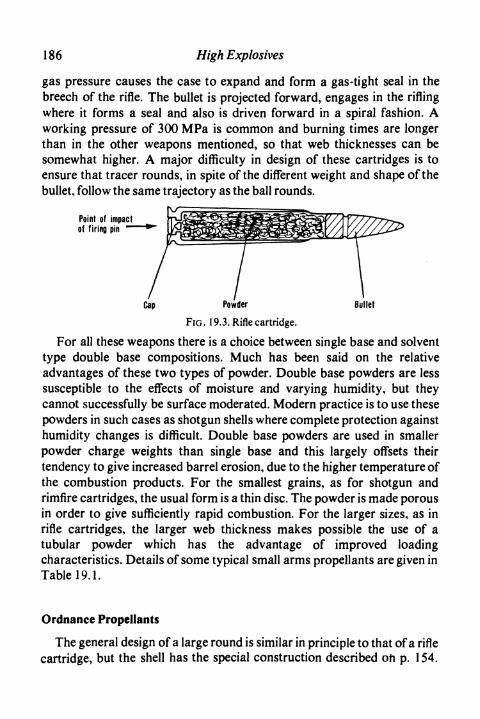
186 High Explosives
gas pressure causes the case to expand and form a gas-tight seal in thebreech of the rifle. The bullet is projected forward, engages in the riflingwhere it forms a seal and also is driven forward in a spiral fashion. Aworking pressure of 300 MPa is common and burning times are longerthan in the other weapons mentioned, so that web thicknesses can besomewhat higher. A major difficulty in design of these cartridges is toensure that tracer rounds, in spite of the different weight and shape of thebullet, follow the same trajectory as the ball rounds.
Point of impactof firing pin •»
Cap Powder Bullet
FIG. 19.3. Rifle cartridge.
For all these weapons there is a choice between single base and solventtype double base compositions. Much has been said on the relativeadvantages of these two types of powder. Double base powders are lesssusceptible to the effects of moisture and varying humidity, but theycannot successfully be surface moderated. Modern practice is to use thesepowders in such cases as shotgun shells where complete protection againsthumidity changes is difficult. Double base powders are used in smallerpowder charge weights than single base and this largely offsets theirtendency to give increased barrel erosion, due to the higher temperature ofthe combustion products. For the smallest grains, as for shotgun andrimfire cartridges, the usual form is a thin disc. The powder is made porousin order to give sufficiently rapid combustion. For the larger sizes, as inrifle cartridges, the larger web thickness makes possible the use of atubular powder which has the advantage of improved loadingcharacteristics. Details of some typical small arms propellants are given inTable 19.1.
Ordnance Propellants
The general design of a large round is similar in principle to that of a riflecartridge, but the shell has the special construction described oh p. 154.

Design and Application ofPropellants
TABLE 19.1 Typical Small Arms Propellants
187
Ammunition
ShotgunRimfire
RevolverRifle
Powder
Type
Double baseDouble base or
single baseDouble baseSingle base
Shape
Porous disc
Porous discPorous discTubular
Dimensions
1-27 mmdiam.
0-89 mmdiam.1-02 mmdiam.1-27 mmdiam.0-38 mmdiam.
Webthickness
0-15 mm
O- 10 mmO- 13 mm0-46 mm
For weapons of larger size, the design of propellent charge can become acomplicated matter of interior ballistics. Because of the long burning time,however, web thicknesses are large and multi-perforated grains can beproduced to give suitable pressure-time curves.
A choice has again to be made between single and double basepropellants. In the past double base propellants tended to be unpopular,because their original high calorimetric value caused gun erosion. This hasnow been overcome. Also the presence of nitroglycerine can givephysiological effects under bad conditions; these, however, no longeroccur in modern equipment. The main advantage of double basepropellants is that they can be produced with low quantities of volatilematerial and also with high stability, so that their ballistic change duringstorage is very small. On the other hand, single base propellants have someadvantages in manufacture and in general can be blended more readily togive required ballistics. Because of the wide variety of weapons, it is notpossible to quote typical grain sizes of web thicknesses.
Ordnance propellants are required to give the minimum of muzzle flash,smoke and barrel erosion. All these objectives are assisted by adding to thepropellant a proportion of nitroguanidine (picrite), made by treatingguanidine nitrate with sulphuric acid and brought to very fine particle sizeby recrystallisation and disintegration.
For the largest weapons, the propellent charge can be kept separatefrom the rest of the round and in this way it is possible to adjust the weightof the propellant to allow for wear of the gun during continued use. Thestorage and handling convenience of a complete sealed round are,however, such that this is the form usually adopted.
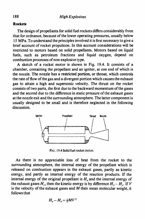
188
Rockets
High Explosives
The design of propellants for solid fuel rockets differs considerably fromthat for ordnance, because of the lower operating pressures, usually below15 MPa. To understand the principles involved it is first necessary to give abrief account of rocket propulsion. In this account considerations will berestricted to motors based on solid propellants. Motors based on liquidfuels, such as petroleum fractions and liquid oxygen, depend oncombustion processes of non-explosive type.
A sketch of a rocket motor is shown in Fig. 19.4. It consists of achamber, containing the propellant and an igniter, at one end of which isthe nozzle. The nozzle has a restricted portion, or throat, which controlsthe rate of flow of the gas and a divergent portion which causes the exhaustgas to attain a high and supersonic velocity. The thrust on the rocketconsists of two parts, the first due to the backward momentum of the gasesand the second due to the difference in static pressure of the exhaust gasesat the nozzle exit and the surrounding atmosphere. The latter component isusually designed to be small and is therefore neglected in the followingdiscussion.
Igniter Propellant Throat Nozzle
FIG . 19.4 Solid fuel rocket motor.
As there is no appreciable loss of heat from the rocket to thesurrounding atmosphere, the internal energy of the propellant which isreleased on combustion appears in the exhaust gases, partly as kineticenergy, and partly as internal energy of the reaction products. If theinternal energy of the original propellant is H0 and the internal energy ofthe exhaust gases He, then the kinetic energy is by difference H0 — He. If Vis the velocity of the exhaust gases and M their mean molecular weight, itfollows that
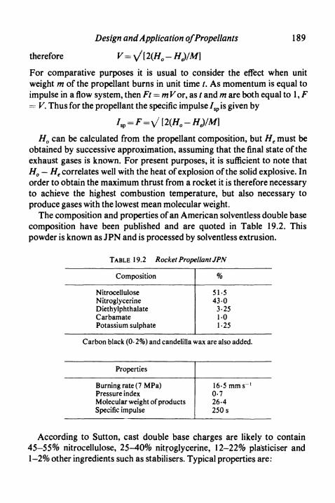
Design and Application ofPropellants 1 89
therefore V= ^/(2(H0-HJfM]
For comparative purposes it is usual to consider the effect when unitweight m of the propellant burns in unit time t. As momentum is equal toimpulse in a flow system, then Ft = m For, as t and m are both equal to 1 , F= F. Thus for the propellant the specific impulse /sp is given by
H0 can be calculated from the propellant composition, but H6 must beobtained by successive approximation, assuming that the final state of theexhaust gases is known. For present purposes, it is sufficient to note thatH0 — He correlates well with the heat of explosion of the solid explosive. Inorder to obtain the maximum thrust from a rocket it is therefore necessaryto achieve the highest combustion temperature, but also necessary toproduce gases with the lowest mean molecular weight.
The composition and properties of an American solventless double basecomposition have been published and are quoted in Table 19.2. Thispowder is known as JPN and is processed by solventless extrusion.
TABLE 19.2 Rocket Propellant JPN
Composition
NitrocelluloseNitroglycerineDiethylphthalateCarbamatePotassium sulphate
%
51-543-0
3-251-01-25
Carbon black (0-2%) and candelilla wax are also added.
Properties
Burning rate (7 MPa)Pressure indexMolecular weight of productsSpecific impulse
16-5 mm s"1
0-726-425Os
According to Sutton, cast double base charges are likely to contain45-55% nitrocellulose, 25-40% nitroglycerine, 12-22% plasticiser and1-2% other ingredients such as stabilisers. Typical properties are:

190 High Explosives
Burningrate(7 MPa) 5-6-9-4 mms'1
Pressure index 0-1-0-8Molecular weight of products 22-28Specific impulse 160-220 s
For composite propellants the properties depend on the proportion ofbinder, and also on whether high energy fuels such as aluminium havebeen added. Figure 19.5, taken from Barrere, Jaumotte, de Veubeke andVandenkerckhove, shows how the specific impulse depends on thesefactors.
260
250
13Q.E 240
230
22020 30
Binder percentage, %
FIG. 19.5. Specific impulse of composite propellants.
The design of the grain is as important as the selection of the propellant.A rocket is required to have a uniform thrust throughout the period ofburning. As the grains, like all propellants, obey Piobert's Law, it isnecessary to achieve a uniform area of burning surface through the wholeprocess of burning. As the motors are in general cylindrical, the propellentgrain must follow this shape in external diameters. In the most important

Design and Application ofPropellants 191
case, the outside of the grain is either bonded to the case, or is otherwiseinhibited from burning. Burning, therefore, occurs only on the internalsurface of the charge. A simple tubular charge burns with graduallyincreasing surface and therefore with gradually increasing release rate ofgas. In order to achieve uniform release rate more complicated shapes areemployed. Two such shapes are shown in Fig. 19.6 and are known as starcentre and clover leaf charges. In each of these the initial burning area isequal to the outside area of the charge, so that the burning area remainsessentially constant. Sometimes more than one composition may beemployed in order to achieve suitable burning rates. Some allowance mustalso sometimes be made for increased burning speed in the initial stages ofcombustion due to the erosive effects of the products of combustionpassing along the initial narrow channel of the charge.
Clover leaf Star centre
FIG. 19.6. Rocket charge sections.
A list of missiles using solid fuel rockets is quoted from Daboo in Table19.3.
In the design of a charge for a rocket the quantities given are theexpected total weight of the rocket, the maximum acceleration which thecharge may give and the time for which this stage of the rocket shouldburn. The last two factors will determine the ultimate speed of the rocket.The maximum pressure for which the motor body is to be designed willalso be given.
From the time of burning and the known pressure, together with the rateof burning equation for the selected propellant, the web thickness iscalculated. This gives the size and cross-sectional area of the grain,assuming that it is radial burning, probably with a star centre. The totalthrust required divided by the specific impulse gives the weight of thecharge. As the cross-section is known the length of the charge can then becalculated. In actual practice, calculations are much more complicated, asthey must allow for inefficiencies in the system and for air resistance andmust also be carried out for various ambient temperatures which may

192 High Explosives
II
S1
§rn
UU
03
c.0'5
Q.
(X
O
Des
igna
ti
•*-»
!31cd
I?Z±
O
IjD
lepa
ratin
g
•° «'§1
ed «>
Fire
flash
!«0
2
i_
2•
o feO C
ctf to
Il
Fire
stre
akSp
arro
w
.
;-sus
tain
er
C/5
2>
I
Falc
on
.:-s
usta
iner
Inte
rna
KJ
I
»0
O
I
•36
I3
OO
t«
JOD
Ilcd ^CX to
E -,ea•o £
.
Ter
rier
8
i
-
tain
er.
CO3CA
CL)
IC/J "jjj
-118.||C —I g
T3 E
Nik
e- A
j ax
.
;-sus
tain
er13C
I
UaS *""
-4-J
^
lepa
ratin
gin
er.
•Q •«-»c S2
Ms2 S
•o
Seas
lug
Thun
derb
iri
8
ICM
OO
s
CA
ratin
g bo
oin
er.
CX to
C —"O U9
£JCO
"3N
ike-
Her
e
8»n
<N
IiI
IJD
lepa
rati
ngne
r.
•53C to
If
T3
5
on
I
'I «3C
« 'rtfrts% 3c ™I *"° 6*crt c^H*
I

Design and Application ofPropellants 193
Inte
rnal
boo
st.
No
sust
aine
r.
a.ICQ
Inte
rnal
boo
st-s
usta
iner
.
o**?
Nor
d A
.S
250-
500
T
Bal
listic
mis
sile
.
1
O
8(NCO
-
U
O £
.h 3
^.
Jj'SI
"3C
is>Q
83
II
Inte
rnal
boo
st.
No
sust
aine
r.La
cros
se50
0-15
00
CN
?
Sing
le-s
tage
bal
listic
mis
si
I
500O
-750
0
S
i
Sepa
ratin
g bo
ost.
Tur
boje
t sus
tain
er.
Mat
ador
Reg
ulus
Sepa
ratin
g bo
ost.
Ram
jet
sust
aine
r.
cO
g
"35
11
IH
CO £•c :sCd CO
»0
I
^2
?OO
Sepa
ratin
g bo
ost.
Tur
boje
t sus
tain
er.
1CO
^igE
1
1
fCA
I
BM
inut
em.-
25 O
OO
-50
000
+
OO
oo J«u» 33 CA
CO
•§
1
fCA
_4>
bOC
ifJS
j^
3 -^
1.1I2
0>TJ
OX)'S S"? "c 5
•^ 1 SZ
!.
Four
-sta
ge v
ehic
le w
ith s
iipr
opel
lant
mot
or in
eac
h s
IO
C/3
I
•O
D.3 OO
*^3 *-Il|s
l_
0>
•— CU 3CQ j^
C^

194 High Explosives
occur during use. Moreover, the burning pressure is probably notoriginally quoted, but deduced from consideration of its effect on the sizeand design of the motor itself.
Such a charge must in use perform regularly and give constant thrust.Should, for any reason, a slight increase in pressure in the chamber occur,two opposing factors operate:
1. The gases flow out from the chamber through the nozzle at anincreased rate.
2. Gases are produced more rapidly by the propellant because of theincreased pressure.
It can be shown that if the pressure index of the propellant exceeds 1 therate of gas increase by factor 2 exceeds the rate of gas loss by factor 1, sothat the pressure builds up in the motor, which finally explodes. Quiteapart from such an extreme case, a low pressure index in the propellant isdesirable so that irregularities in burning are quickly smoothed out withthe least effect on rocket performance. It is for this reason that platonisingagents mentioned on p. 181 are important, because they enable a very lowpressure index to be achieved at ordinary operating pressures of the orderof 14 MPa.
Power Cartridges
Special slow burning cool propellants can be used to generate gas underpressures suitable for the operation of mechanical devices. Perhaps themost important of these applications is in cartridge starting of jet enginesfor aircraft. The principles involved in this application of propellentexplosives are illustrated in Fig. 19.7.
Plastic disc - - Electricfuze
Propellant lflniter
FIG. 19.7. Engine starter cartridge.

Design and Application ofPropellants 195
The propellant is usually either tubular or cigar burning, depending onthe required time of operation. It is enclosed in a pressure chamber fromwhich the gases are led through an orifice which controls the flow andregulates the pressure. A pressure relief valve is included for safetyreasons. The hot gases from the orifice are taken to an impulse turbinewhich is geared to the rotor of the jet engine.
A jet engine has a compressor which provides compressed gas to acombustion chamber where the fuel is burnt. The hot gases from thecombustion chamber pass through a turbine, which drives the compressor,and thence go to the jet. For the engine to be started the compressor mustbe driven above a critical speed, below which the power given by theturbine is insufficient to drive the compressor. The advantage of propellentcartridges for starting jet engines is that they enable the compressor andturbine to be brought to the critical speed in a matter of seconds. When thisspeed is reached fuel injection is provided into the combustion chamberand the engine is then capable of being run to its idling speed or above.
For civilian aircraft the facility for rapid starting is not important andcartridge operation is not often employed, particularly because it involvesstoring and handling explosives, even though the hazards of theseexplosives are those of fire and not of detonation. For military purposes,however, particularly for fighter aircraft which are best scattered on anairfield, a rapid start is of considerable importance. Therefore cartridgeoperated starters are much used for these aeroplanes. In Britain,development has been essentially with propellants based on ballistite,namely double base propellants of the solventless type, whereas in theUnited States composite propellants based on ammonium nitrate haveproved more popular.
Electrically Actuated Devices
Electrically actuated devices (explosive motors) of small size are findingvaried and increasing uses. Typically they contain a fusehead and in thelarger sizes also a small charge of a propellent explosive such asblackpowder. This is sealed in a strong metal tube so that the finisheddevice offers no explosive hazard. The firing of the fusehead can forexample drive a captive piston a small distance outwards at the end of thetube. This in turn can be used to open or close a switch or valve or to worka guillotine cutter. These actuators have great reliability even after long

196 High Explosives
storage under adverse conditions and give strong rapid action from smallelectrical inputs. These properties make them of value in applications suchas safety and security systems and in fire protection.
References
BARRERE, M., JAUMOTTE, A., DE VEUBEKE, B. F., and VANDENKERCKHOVE, J., RocketPropulsion. Elsevier, Amsterdam, 1960.
CORNER , J., Theory ofthe Interior Ballistics of Guns. Chapman & Hall, London, 1950.DABOO, J. E., Solid-fuel Rocket Propulsion. Temple Press, London, 1962.HUGGET, C., HARTLEY, C. E., and MILLS, M., SolidPropellant Rockets. Princeton Univ.,
Princeton, 1960.OHART, Maj. T. C., Elements of Ammunition. Chapman & Hall, London, 1946.SUTTON , G. P., Rocket Propulsion Elements. Wiley, New York, 2nd ed. 1956.TAYLOR, J., Solid Propellent and Exothermic Compositions. Newnes, London, 1959.WHELEN, Col. T., Small Arms Design and Ballistics. Small Arms Technical Publishing
Co., Plantersville, S. Carolina, 1945.

Glossary of Common Termsand Abbreviations
Abel Heat Test A quick routine test for demonstrating the absence from explosives ofimpurities causing low thermal stability (see p. 72).
A.D.C. Ardeer Double Cartridge Test. A test measuring the ability of cartridges ofexplosive to propagate over air gaps (see p. 68).
Advance. In mining or tunnelling, the distance by which the face or tunnel is movedforward by each round of blasting (see p. 138).
Airdox. A blasting device based on compressed air (see p. 89).Amatol. A mixture of ammonium nitrate and trinitrotoluene.Ammon gelignite. A nitroglycerine gelatine explosive containing ammonium nitrate as the
main oxidising ingredient.Ammonal. An explosive containing ammonium nitrate, trinitrotoluene and aluminium.AN. Ammonium nitrate.ANFO. An ammonium nitrate/fuel oil explosive.Application time. In firing electric detonators, the time for which the electric current is
applied (see p. 112).B. and J. Bergmann and Junk. Test of stability (see p. 72).Base charge. In a detonator, the charge of high explosive which makes the major
contribution to the power of the device.Boost In rocketry, a motor which gives rapid acceleration for a short period.Braid. To enclose in criss-crossing yarns of textile.Break. In mining, a separation between strata or along a cleavage plane in coal or rock.Break gallery. An experimental installation to assess the hazards of firing explosives in coal
mines in the presence of breaks (see p.80).Bridge wire. The fine wire in an electric detonator which is heated by the firing current.Brisance. The shattering power of an explosive.Briska detonator. A detonator in which extra power is achieved by extremely heavy
pressing of the base charge.Bulk strength. The strength per unit volume of an explosive, usually expressed as a
percentage of the strength per unit volume of blasting gelatine.Burden. In blasting, the shortest lateral distance between a borehole and a free face.Bunting time. In firing electric detonators, the time between the application of the electric
current and the explosion of the detonator (see p. 112).Cap. A metal shell with pyrotechnic filling, such as is used in small arms ammunition for
causing a mechanical blow on the outside of the shell to ignite the propellent chargeinside. In the U.S.A. detonators are known as blasting caps.
Carbarn ate. Symmetrical diethyldiphenylurea.Card ox. A metal tube device using carbon dioxide to produce a blasting effect (see p. 89).C.D.B. Cast Double Base Propellant (see p. 174).C.E. Composition Exploding. Tetryl, usually in the form of a pellet.
197

198 Glossary of Common Terms and Abbreviations
Centralitc. Symmetrical diethyldiphenylurea.Cigar burning. In propellants, the burning of a cylindrical charge from one end only, the
other surfaces being inhibited.C.-J. Chapman Jouget (see p. 19).Clearing Test A test of the speed of solution of nitrocellulose in nitroglycerine (see p. 74).Composite propellent A propellant based on an oxidising salt and an organic fuel/binder.Cordtcx. British trade name for detonating fuse.Corning. In blackpowder manufacture, the stage of the process which produces uniform
spherical grains.Counter. In fuse manufacture, to wind on textile yarns in a direction opposite to a previous
spinning process.Crimping. Squeezing a metal tube round a plug, fuse, or similar body to secure the latter
firmly.DDNP. Diazodinitrophenol (see p. 97).Deflagrating explosive. An explosive which burns rapidly but does not detonate.Deflagration. In high explosives, a relatively slow decomposition accompanied by fumes
but not normally by flame.Delay detonator. A detonator in which a time lag is introduced between application of the
firing current and explosion of the detonator.Detonating fuse. A fuse with a core of detonating explosive.Detonation. An explosion process of high speed involving a sustained shock wave.Detonator. A metal tube containing a primary explosive used for initiating a secondary
explosive.Double base propellant. A propellant based on nitrocellulose and nitroglycerine.Drift In coal mining, an underground tunnel through stone.Electric detonator. A detonator for firing by electric current. The term does not normally
include delay detonators.End spit. The flash of burning material ejected from safety fuse when burning reaches a cut
end.Eq.S. Equivalent to Sheathed. The original name for Group P3 Permitted Explosives.Excitation time. In firing electric detonators, the interval between the application of the
current and the firing of the fusehead (see p. 112).Explosion. A liberation of energy sufficiently sudden to cause dynamic stress to the
surroundings.Explosive. A chemical, or mixture of chemicals, which can react so rapidly and with such
liberation of energy that there can be damage to the surroundings.Explosive motor. A device in which explosive is completely enclosed and which on
operation causes a mechanical movement as of a piston (see p. 195).Exudation. In nitroglycerine gelatine explosives, a liberation of nitroglycerine following
breakdown of the gelatinous base.Fall hammer test. A test of the sensitiveness of explosives to impact using a weight which
falls vertically (see p. 69).Fizz zone. In the burning of propellants, the zone in which the solid propellant is converted
to gaseous intermediates (see p. 182).Flame zone. In the burning of propellants, the final stage in which gaseous intermediates
react with the production of a flame (see p. 182).Flash past. In assemblies such as delay detonators and military fuzes the possibility of an
igniting flash by-passing a delay element.Foam zone. In the burning of propellants, the initial stage of partial gasification (see p.
182).

Glossary of Common Terms and Abbreviations 199
Free face. In blasting, a face of rock or coal approximately parallel to the line of boreholes(seep. 138).
Fulminating compound. An early term, applied to mixtures of chemicals usuallycontaining silver and used essentially for pyrotechnic purposes.
Fume. In mining, the gaseous products of an explosion.Fuse. A cord for transmitting explosion from one site to another.Fusehead. Ignition element for an electric detonator.Fuze. Military device for initiating an explosive charge.Gaine. An intermediate booster charge used between a detonator and an insensitive high
explosive.Gallery. Equipment for firing explosives into incendive mixtures of methane and air.Gasless delay detonator. Original name for modern delay detonator.Gassy coal mine. A mine in which methane may be present; also known as a safety lamp
mine.Gelatine. An explosive which is a jelly of nitroglycerine containing nitrocellulose, usually
with oxidising salts and solid fuel dispersed in it.Gelignite. Originally a gelatine explosive containing potassium nitrate as oxidising
material. Now often applied to any gelatine.Grain. A unit of propellent powder.Guncotton. Nitrocellulose containing more than 12-6% of nitrogen.Heat Test A rapid stability test depending on detection of traces of products of
decomposition of an explosive at an elevated temperature. In Britain this usually refersto the Abel Heat Test.
Hess Test A German test for brisance (see p. 73).High explosive. Literally any explosive which detonates. In practice, the term is usually
confined to explosives which do not normally burn to detonation but which require adetonator for use.
High tension detonator. An early form of detonator which required a voltage exceeding36 volts to fire it (see p. 107).
HMX.Cyclotetramethylenetetranitramine.Hydrox. A steel tube device using low temperature gas produced from a chemical cartridge
for producing a blasting effect (see p. 89).Igniter cord. A cord for igniting safety fuse.Induction time. In firing electric detonators, the time between the breaking of the fuse wire
and the detonation of the base charge (see p. 112).Initiating explosive. An explosive which when lit by a flame immediately detonates.Instantaneous fuse. A fuse which propagates by burning at high velocity.Kast Test A German test for brisance (see p. 73).Lag time. In firing electric detonators, the interval between the application of the current
and the breaking of the bridge wire (see p. 112).L.E.D.C. Low Energy Detonating Cord. A detonating fuse with a core charge too low to
enable it to be used reliably for initiating high explosives (see p. 124).Long wall mining. In coal mining, a method of working in which the coal is won along a
face 100 to 20Om long.LOX. Liquid Oxygen Explosive (see p. 59).Mfll cake. In blackpowder manufacture, a product taken from the edge runner mills.Millisecond delay detonator. A short delay detonator.Moderated. In propellants, implies the presence of a surface coating to the grain which
slows down the initial rate of burning.NC. Nitrocellulose.

200 Glossary of Common Terms and Abbreviations
NG. Nitroglycerine.NS gelignite. A nitroglycerine gelatine explosive containing sodium nitrate as its main
oxidising ingredient.Opencast mining or strip mining. Obtaining coal or ore which is near the surface by
removing the overlying soil and rock to expose the coal or ore for direct recovery.Ordnance. The larger size military guns and mortars.Pl. The first and strongest class of Permitted Explosive.P2. Originally called sheathed explosives, consist of Pl explosives enclosed in a sheath to
give increased safety.P3. Class of Permitted Explosives for general use with instantaneous detonators.P4. Class of Permitted Explosives particularly for ripping with short delay detonators.P5. Class of Permitted Explosives particularly for firing with short delay detonators in solid
coal.Paste. In double base propellant manufacture, the initial mixture of guncotton and
nitroglycerine.Pentolite. A mixture of TNT and PETN.Permissible Explosive. The American equivalent to British Permitted Explosive.Permitted Explosive. An explosive which is authorised for use in gassy coal mines.PETN. Pentaerythritol tetranitrate.Phlegmatise. To add a proportion of oil or other ingredient to render an explosive
insensitive.Picrite. Nitroguanidine.Pillar and stall mining. A method of mining in which pillars are left to support the roof.Plain detonator. An open detonator with no means of ignition attached.Platonisation. In propellants, the addition of ingredients to produce a low pressure index
over a working range of pressures.Powder. A generic name for a propellent explosive.Presplitting. A technique of blasting which gives accurate finished contours (see p. 148).Press cake. In blackpowder manufacture, a cake taken from the presses.Pressure index. In propellants, the variation of burning speed following changes in pressure
(seep. 180).Prill. An absorbent spherical form of a product, particularly ammonium nitrate.Primary explosive. An alternative name for an initiating explosive. A flame causes the
explosive to detonate immediately.Primer. High explosive charge used to initiate other high explosive.Priming charge. In detonator manufacture, the charge of initiating explosive.Propellant. An explosive which normally burns and does not detonate.Propellent. Adjective implying the possession of a propulsive effect.RDX. Cyclotrimethylenetrinitramine.Reaction time. In firing electric detonators, the time between the ignition of the fusehead
and the explosion of the detonator (see p. 112).Ripping. In coal mining, the removal of stone after recovery of coal to produce a road of
normal size (see p. 143).Safety fuse. A fuse which propagates by slow burning.Safety lamp mine. Alternative name for gassy mine, implying possible presence of
methane.Secondary blasting. A process of breaking, with explosives, boulders from an initial blast
which are too large for immediate handling.Secondary explosive. Alternative name for high explosive indicating that the explosive does
not burn to detonation but is detonated by suitable devices.

Glossary of Common Terms and Abbreviations 201
Semi-gelatine. An explosive containing nitroglycerine gelled with nitrocellulose, but inquantity insufficient to fill the voids between the salt and combustible particles andthereby produce a gelatine.
Shaped charge. An explosive charge designed to produce specific effects by the inclusion ofa re-entrant conical or V shape usually lined with metal.
Shock wave. A pressure wave of high intensity characterised by a very rapid initial increasein pressure followed by a slow falling off.
Short delay detonator. A delay detonator with time interval between individuals of theseries of 25 or 50 ms.
Single base propellent. Propellant based on nitrocellulose without the inclusion ofnitroglycerine.
Slurry explosive. An explosive made by sensitising a thickened aqueous slurry of oxidisingsalts (see p. 55).Small arm. A gun or rifle of up to about 2-5 cm in calibre.Solid coal. Implies coal which is being worked without the provision of a free face by
undercutting or similar means.Solvent type propellent. A double base propellant in which solvent is used to assist the
gelatinisation of the nitrocellulose.Solventless double base propellant. A double base propellant in which gelatinisation is
effected by mechanical means without the addition of solvent.Spalling. In explosives technology implies the breaking off of a scab of material from a free
face as a result of the reflection of shock waves (see p. 135).Special gelatine. A gelatine explosive in which the main oxidising ingredient is ammonium
nitrate.Spin. In fuse manufacture, to wind on a spiral of textile yarns.Stemming. The insertion, into the end of a borehole, of clay or other material which will
resist the pressure of the explosive when the latter is fired.Streaming velocity. The velocity of the products of detonation in the direction of travel of
the detonation wave.Strip mining. See Opencast mining.Sustainer. In rocketry, a slow burning motor to produce a continued thrust.TNT. Trinitrotoluene.Torpedo friction test. A test of sensitiveness to impact and friction (see p. 70).Triple base propellant. A propellant containing nitroglycerine, nitrocellulose and Picrite.Tun dish. A large unstirred cylindrical vessel used for slow processes of steeping or
steaming.Undercutting. In coal mining, the production of a free face by cutting out mechanically the
lowest 10 to 12 cm of a seam (see p. 142).VOD. Velocity of detonation, usually measured in metres per second.Web thickness. The distance of travel of a burning surface in a propellent grain to give
complete combustion.Wedge cut. A method of tunnelling, etc., in which a free face is first produced by blowing
out a wedge of rock.Weight strength. The strength per unit weight of an explosive, usually expressed as a
percentage of the strength per unit weight of blasting gelatine.Zapon. A solution of nitrocellulose used in fusehead manufacture.

Index
Abel equation of state 19,179Abel heat test 72A.D.C.test 68Airdox 89Amatol 31Ammon gelignite
design 53manufacture 42
Ammonium nitrate 35dense 35for ANFO 36,48for nitroglycerine explosives 35,49,
50,54for TNT explosives 54prills 36
ANFOdesign 48effect on sales 6introduction 14loading 141,147manufacture 41
Angle shot mortar 82Annual production, commercial
explosives 4Ardeer 3Authorised definition 8
Bacon, Roger 2Ballistic mortar 62Ball powder 173B. and J. test 72Bickford 3Blackpowder 164
burning mechanism 166discovery 2manufacture 164properties 165
Blasting principles 135Blasting gelatine
invention 13properties 51
Bombs 156Break test 80,86Brisance 73Briska detonator 103British Dynamite Company 3
Calorimetric value, propellants 178Cardox 89Carrick delay detonator 120Cast double base propellant 169
composition 189manufacture 174
C.E. 33C hapman-Jouguet condition 19Chlorate blasting explosive 60Cladding metals 151Clearing test, nitrocellulose 74Coal dust explosion 75Coal mines
explosive usage 5mechanisation 6,144
Coalmining 142see also Permitted explosives
Commerical explosivescompositions 47,84properties 21usage 4
Composite propellant 169,190burning mechanism 183manufacture 175
Consumption by industry, U.S.A. 5Copper azide 96,101Cordeau 121Costs 5Cratering 137CTMTN 32Cyclonite 32Cyclotrimethylenetrinitramine 32
Dautriche method 66Delay compositions 117
203

204 Index
Delay detonator 115assembly 118coalmining 119design 119types 116
Delay element manufacture 118Detonating fuse 121
dry process 122manufacture 122properties 123use 147wet process 123
Detonation pressure r 21Detonation wave 17,24Detonator 100
certainty of ignition 101design 103initiating power 102invention 13manufacture 104safety 100stability 101testing 105
Diazodinitrophenol 97Double base propellant 169
ball powder 173burning mechanism 182compositions 171manufacture 172sol vent type 173solventless 174
Electric detonator 107assembly 111firing characteristics 112series firing 113types 107
Electrically actuated device 195Energy of explosives 20,21Engine starter cartridge 194Equations of state 19,179Esoptest 105Ethylene glycol dinitrate 38Explosive
definition 2types 3
Explosive motor 195Explosives Acts 8
Explosives and Chemical ProductsLimited 4
Export of explosives 5Exudation 49,52,72
Factory constructionhigh explosives 44propellants 177
Factory licence 8Fall hammer test 69Faversham 3Firedamp ignitions 75
see also Methane/air ignitionsFriction sensitiveness, testing 69Fritzsche safety fuse 128Fume 46
testing 73Fuse see Detonating fuse, Instantaneous
fuse, LEDC, Nonel, Safety fuseFusehead 108
bridge wire 110dips 110firing characteristics 112series firing 113
Gallery testing 78,82,85,86,87Gelatine explosive
design 51manufacture 42
Gelignitedesign 52manufacture 42
Greek fire 2Grenade 153Guhr dynamite 13Guncotton 3,39,40Gunpowder
discovery 2see also Blackpowder
Heat test 72Hexogen 32High tension detonator 107H.M. Inspectors of Explosives 8HMX 33Hydrodynamic theory of detonation 18
small cartridges 24solid ingredients 20
Hydrox 89
Index 205
Igniter cord 130use 148
Igniter cord connectors 131Impact sensitiveness, testing 69Imperial Chemical Industries Limited 4Imperial Metal Industries (Kynoch)
Limited 4Initiation of detonation
by burning 27,177by friction 27by impact 27by shock wave 25propellants 177
Instantaneous fuse 129
Nitroglycerine powder explosivesdesign 48manufacture 41
Nobel, Alfred 3,13Nobel Industries Limited 4Nobel's Explosives Company Limited 4None! 125
Ordnance propellant 186Oxygen balance 46
Lead azide 95Lead block test 63Lead plate test
detonators 105high explosives 73
Lead styphnate 97Limpet charge 154LEDC 124Low energy detonating cord 124LOX 59
Mercury fulminate 95,101Metal working by explosives 150Methane/air ignitions 75
ignition mechanisms 75testing 78
Military explosives 29properties 30
Mining 142,145Missiles 192Modderfontein 5
Nail test 105Neumann peak 24Nitrocarbonitrates 59Nitrocellulose 38
clearing test 74discovery 13
Nitrocotton see NitrocelluloseNitroglycerine 36
discovery 13manufacture 37properties 38
P. !explosive 82,143P.2 explosive 83P.3 explosive 85,143P.4 explosive 86,143P.4/5 explosive 88P.5 explosive 87,144Packaging 43
regulations 8Paste mixing 172Pentaerythritol tetranitrate 31Penthrite 31Pentolit 32Perchlorate blasting explosive 60Permitted explosive 75
compositions 84design 77detonation pressure 22uses 143see also P. 1, P.2, P.3, P.4, P.4/5, P.5
explosivesPETN 31Piobert'slaw 181Platonising 181Powder high explosive
design 48,54manufacture 41
Power cartridge 194Power of explosives 27,61Presplitting 148Pressure index 180
rocket motors 194Production statistics 4
206 Index
Propellantburning mechanism 182compositions 171grain design 181rate of burning 179stability 183types 169see also Composite, Double base, Single
base, Solvent type, Solventless, Triplebase
Pulsed infusionexplosive 89technique 143
Quarrying 146
Rankine-Hugoniot curve 19,23propellants 178
RDX 32Rifle ammunition 185Rimfire ammunition 18 5Ripping 79,142,143Rock breaking 135,148Rocket 188Rocket motor 188
design 191Rocket propellant 169
characteristics 190grain design 191
Royal Gunpowder Factory, WalthamAbbey 3
Royal Ordnance factories 4
Safety distances 8Safety fuse 126
manufacture 126properties 128testing 129
Safety in Mines ResearchEstablishment 76
Sales, U.K. explosives andpyrotechnics 5
Secondary blasting 148Seismic prospecting 149
explosive 53Semi-gelatine explosive
design 49manufacture 42
Sensitivenesshigh explosives 67test results 71
Series firing of electric detonators 113Shaped charge 158
commercial 150military 158
Sheathed permitted explosive 83Shell 154Shockwave 15,135
reflection 15,135Shotfiring 140Shotgun cartridge 184Shrapnell shell 156Single base propellant 169
burning mechanism 18 2composition 171manufacture 170
Slurry explosive 55Small arms ammunition 184Small arms propellant 187Sobrero 13,36Solvent type double base propellant 169
composition 171manufacture 173
Solventless double base propellant 169composition 171manufacture 174
Squash-head projectile 159Stability
high explosives 71propellants 183
Stable hole blasting 142,144Stowmarket 3Strand burner 179Streaming velocity 18
calculated 20,21
Tetramethylenetetranitramine 33Tetrazene 98Tetryl 33TNT 30
discovery 13for commerical explosives 40
TNT explosivesdesign 54manufacture 41
Torpedo 15 7Torpedo friction test 70

Index 207
Transport regulations 8 Vielle's equation or lawTrautzl lead block test 63 blackpowder 166Trinitrotoluene see TNT propellants 180Triple base propellant 169,187Tuckingmill 3Tunnelling 138
Underwater explosion 28 Waltham Abbey 3Unifoilfusehead 109 Water-gel explosives 55U.S.A. commercial explosive usage 5 Waterproofing 5055
Web thickness 181Velocity of detonation 17 small arms propellants 187
calculated 20,21 Westquarter 4diameter effect 22 World production, commercialmeasurement 64 explosives 4,6


