High field levels generated by a 12 kW CW wideband power amplifier Dr Cyril Lagarde Dr Ludovic Bacqué PRANA R&D – www.prana-rd.com PRANA R&D – www.prana-rd.com Brive la Gaillarde, FRANCE Brive la Gaillarde, FRANCE [email protected][email protected]Abstract — Many EMC applications (automotive, military…) request more and more field level in order to realize immunity testing. Prana has developed and manufactured a new high wideband power amplifier in the bandwidth 100kHz - 225MHz, named GN12000. Keywords: power amplifier, wideband, high field, EMC, immunity I. INTRODUCTION Prana, a French company, belongs to the worwilde leading manufacturers of RF Power Amplifiers for Broadband applications such as EMC testing, instrumentation and radio-communication. The Prana product lines are all solid state and cover a frequency range from 10kHz to 6GHz with power levels up to 12kW (GN12000). This amplifier provides a CW typical power of 12kW between 100kHz and 225MHz. The class A of the amplifier allows providing the output power at 1dB of compression with a harmonic level less than -20dBc. Integrated into an EMC test system, the goal is to obtain a CW electric field level higher than 200V/m in the frequency range (100kHz – 225MHz). II. PRESENTATION The GN12000 design is modular and modern (figure 1). It is composed of 16 identical power modules, 4 intermediate combiners, 1 final combiner and 1 coupler. The GN12000 was designed for minimal maintenance: easy accessibility of all sub systems and all the modules can be changed each other. Figure 1 : GN 12000 Prana amplifier Figure 2 : GN 12000 architecture
Transcript
High field levels generated by
a 12 kW CW wideband power amplifier
Dr Cyril Lagarde Dr Ludovic Bacqué PRANA R&D – www.prana-rd.com PRANA R&D – www.prana-rd.com
Abstract — Many EMC applications (automotive, military…) request more and more field level in order to realize immunity testing. Prana has developed and manufactured a new high wideband power amplifier in the bandwidth 100kHz - 225MHz, named GN12000.
Keywords: power amplifier, wideband, high field, EMC, immunity
I. INTRODUCTION Prana, a French company, belongs to the worwilde leading manufacturers of RF Power Amplifiers for Broadband applications such as EMC testing, instrumentation and radio-communication. The Prana product lines are all solid state and cover a frequency range from 10kHz to 6GHz with power levels up to 12kW (GN12000). This amplifier provides a CW typical power of 12kW between 100kHz and 225MHz. The class A of the amplifier allows providing the output power at 1dB of compression with a harmonic level less than -20dBc. Integrated into an EMC test system, the goal is to obtain a CW electric field level higher than 200V/m in the frequency range (100kHz – 225MHz).
II. PRESENTATION
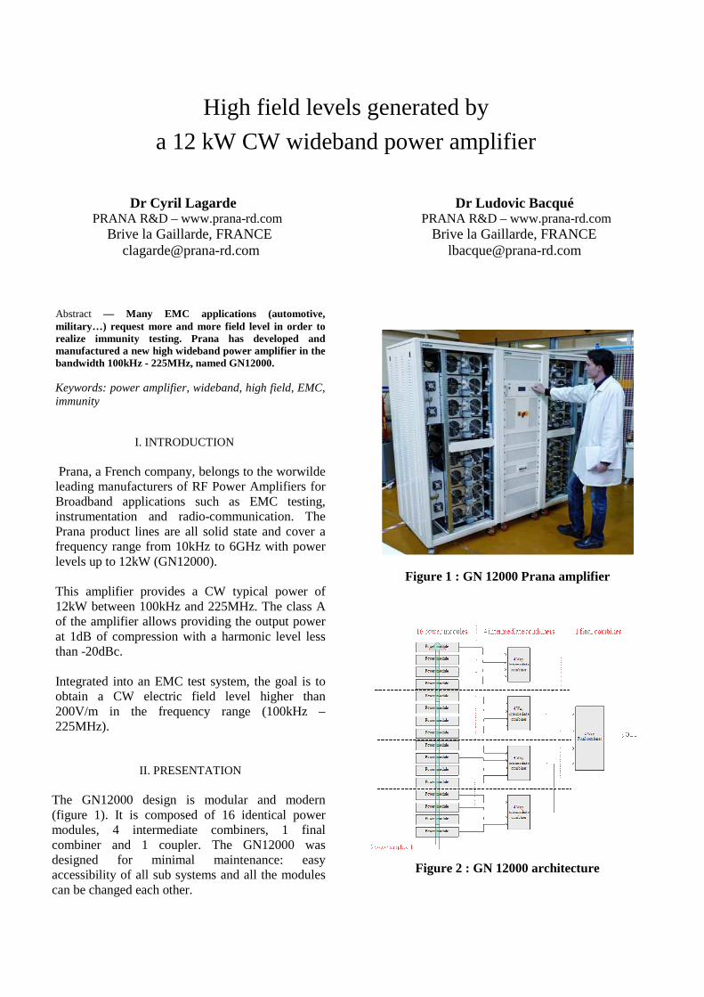
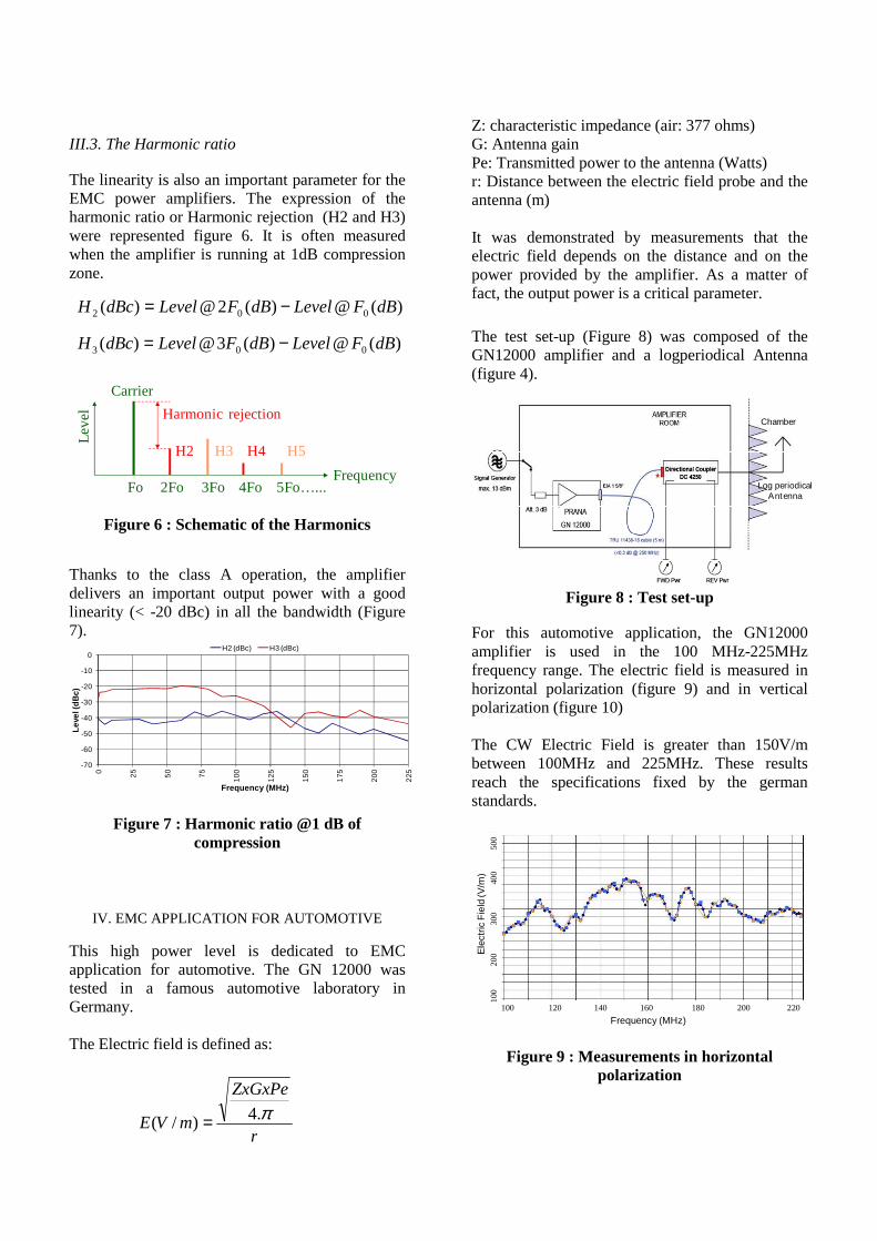
The GN12000 design is modular and modern (figure 1). It is composed of 16 identical power modules, 4 intermediate combiners, 1 final combiner and 1 coupler. The GN12000 was designed for minimal maintenance: easy accessibility of all sub systems and all the modules can be changed each other.
Figure 1 : GN 12000 Prana amplifier
Figure 2 : GN 12000 architecture
One power module provides a typical power of 1kW in the bandwidth. These power modules use LDMOS transistors biased in class A in order to obtain an important output power with a high linearity. Each power module contains its own cooling system (DC fans and heat sink). The GN12000 was designed in 4 identical parts (figure 2) in order to be upgradable easily.
III. MEASUREMENTS The GN12000 was tested in the Prana laboratory using a test set-up represented in the figure 3. The 50 ohms load is cooled by water and supports 35kW CW. This automatic test bench allows to measure: - Small signal gain. - Output powers at 1dB and 3 dB of compression. - Harmonic ratio.
Figure 3 : Prana Test bench
III.1. The small signal gain The small signal gain is defined as: b2: transmitted wave at the output a1: incident wave at the input
The GN12000 provides a typical gain of 69dB (figure 4) with a flatness of +/- 2 dB.
+71 dB
+69 dB
+67 dB
Figure 4 : Small Signal Gain (S21 parameter)
III.2. The Output power
The output power has been measured at 1dB (green curve – figure 5) of compression and 3dB of compression (red curve - figure 5). The measured CW output power at 3 dB of compression is greater than 10kW up to 150MHz.
The amplifier was designed to provide much more power at the beginning of the bandwidth in order to offset the wideband antenna gain.
0
2000
4000
6000
8000
10000
12000
14000
16000
0 25 50 75 100 125 150 175 200 225
Ou
tpu
t po
wer
(Wat
t)
Frequency (MHz)
Linear Output Power (Compression max. = 1 dB) Saturated Output Power (Compression max. = 3 dB)
obtained with
Harmonics < - 20 dBc
Figure 5 : Output power at 1 dB and 3 dB of compression
0,1
221
2
)(=
=adB
a
bdBS
b2
b1 a2
a1
Frequency (MHz) G
ain
S21
(dB
)
III.3. The Harmonic ratio The linearity is also an important parameter for the EMC power amplifiers. The expression of the harmonic ratio or Harmonic rejection (H2 and H3) were represented figure 6. It is often measured when the amplifier is running at 1dB compression zone.
Leve
l
FrequencyFo 2Fo 3Fo 4Fo 5Fo…...
Carrier
H2 H3 H4 H5
Harmonic rejection
Figure 6 : Schematic of the Harmonics
Thanks to the class A operation, the amplifier delivers an important output power with a good linearity (< -20 dBc) in all the bandwidth (Figure 7).
-70
-60
-50
-40
-30
-20
-10
0
0 25
50
75
100
125
150
175
200
225
Lev
el (d
Bc)
Frequency (MHz)
H2 (dBc) H3 (dBc)
Figure 7 : Harmonic ratio @1 dB of compression
IV. EMC APPLICATION FOR AUTOMOTIVE
This high power level is dedicated to EMC application for automotive. The GN 12000 was tested in a famous automotive laboratory in Germany. The Electric field is defined as:
Z: characteristic impedance (air: 377 ohms) G: Antenna gain Pe: Transmitted power to the antenna (Watts) r: Distance between the electric field probe and the antenna (m) It was demonstrated by measurements that the electric field depends on the distance and on the power provided by the amplifier. As a matter of fact, the output power is a critical parameter.
The test set-up (Figure 8) was composed of the GN12000 amplifier and a logperiodical Antenna (figure 4).
Log periodicalAntenna
Chamber
Figure 8 : Test set-up
For this automotive application, the GN12000 amplifier is used in the 100 MHz-225MHz frequency range. The electric field is measured in horizontal polarization (figure 9) and in vertical polarization (figure 10) The CW Electric Field is greater than 150V/m between 100MHz and 225MHz. These results reach the specifications fixed by the german standards.
Frequency (MHz)
Ele
ctric
Fie
ld (V
/m)
100 120 140 160 180 200 220
100
2
0030
040
050
0
Figure 9 : Measurements in horizontal polarization
)(@)(2@)( 002 dBFLeveldBFLeveldBcH −=
)(@)(3@)( 003 dBFLeveldBFLeveldBcH −=
r
ZxGxPe
mVE π.4)/( =
Figure 10 : Measurements in vertical polarization
V. EMC APPLICATION FOR MILITARY
The GN12000 was also tested in a famous military laboratory in France. The amplifier was introduced in a stripline system (Figure 11).
Figure 11 : Military stripline antenna
The figure 12 represents the measured Electric field with different constant input CW powers (-16dBm to + 3dBm) between 100kHz and 200MHz. Thanks to the GN12000, the system is able to deliver a CW electric field greater than 400V/m in the test bandwidth. Also, the amplifier is running in a linear area which allows the engineers to use this amplifier with AM modulated signal for example.
Frequency (Hz)
Ele
ctric
Fie
ld (V
/m)
200
100
300
400
500
600
100 k 1 M 10 M 100 M
- 16 dBm
- 10 dBm
- 3 dBm
0 dBm
3 dBm
Figure 12 : Measured Electric Field
V. CONCLUSION
The GN12000 amplifier was tested in different conditions, with a 50 ohms load and with different antennas. Several applications are presented in this final paper. All these tests validate the GN12000 capability to generate high CW field levels (> 150V/m) and this reliability with high mismatched loads.
AUTHOR’S BIO-DATA
Cyril Lagarde was born in Argenteuil (near Paris), France, in 1980. He received the Electronical Master’s Degree in 2003, and the PhD degrees in High Frequency Electronics from the University of Limoges, France, in 2006. Since 2006, he has joined the Prana Company. His works area of interest are broadband amplifier designs.
Ludovic Bacqué was born in Périgueux (near Bordeaux), France, in 1980. He earned an engineering degree in 2004 and the PhD degrees in High Frequency Electronics from the University of Limoges, France, in 2008. Since 2008, he has joined the Prana Company. His works area of interest are broadband amplifier designs.