GCL-GCD_030216 Copyright copy 2016 by Global Manufacturing Inc
GCL
GCD
Global Manufacturing Inc reg 8005513569 TOLL FREE USA amp CANADA1801 East 22nd Street 5013747416 TEL 5013767147 FAXLittle Rock AR 72206 USA wwwG l oba lManu f a c t u r i ng c om
2
Table of Contents PageI Introduction 2
II Installation Procedures 3
III Mounting 4 - 5
IV Operation 6
V Assembly amp Disassembly Procedures 6 - 7
VI Vibrating Wet Concrete 8 - 10
VII Vibrator Orientation 11
VIII Parts Explosion - GCD 12
IX Parts Explosion - GCL 13
X Vibrator Dimensions - GCD amp GCL 14
XI Bracket Dimensions 15
XII Performance Data amp Lubrication 16
XIII Troubleshooting 17
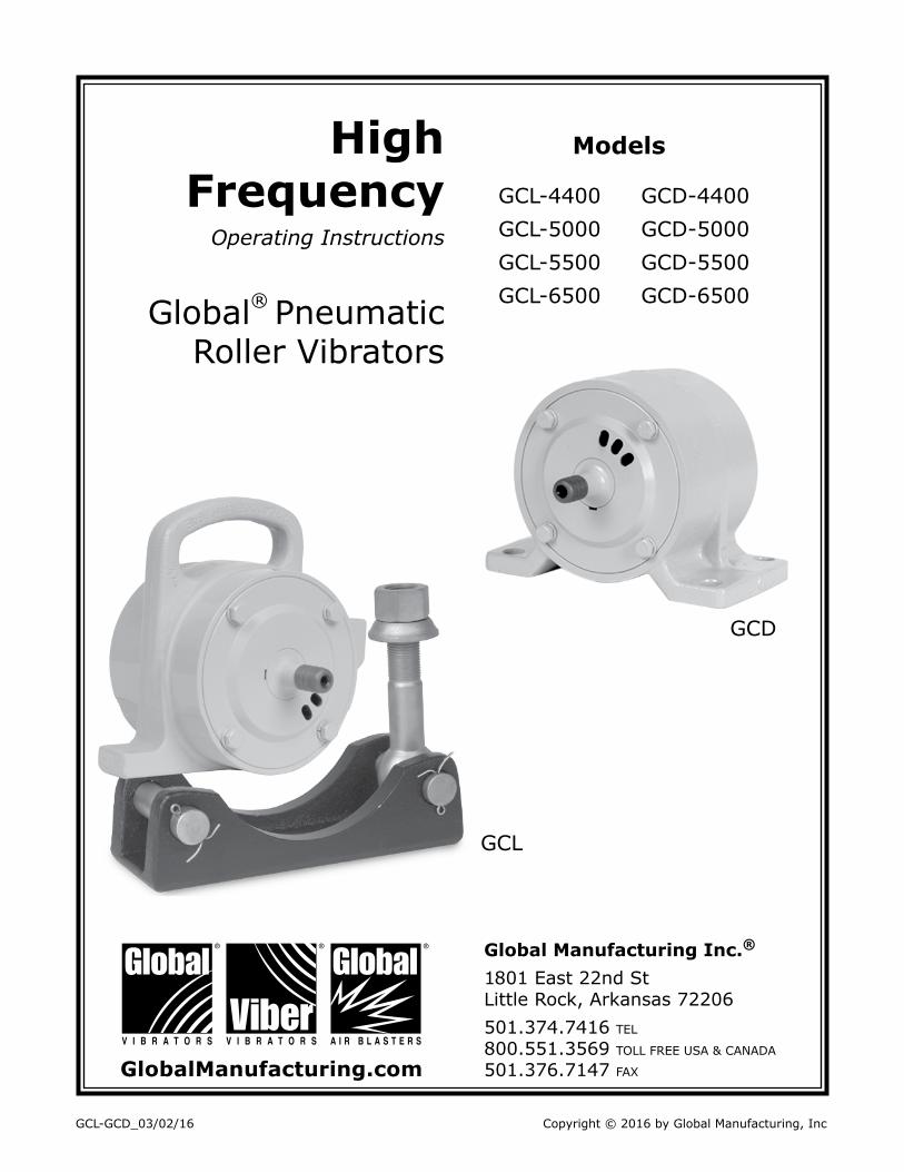
I IntroductionYou have purchased a GCL-4400GCD-4400 GCL-5000GCD-5000 GCL-5500GCD-5500 or GCL-6500GCD-6500 High Frequency vibrator manufactured by Global Manufacturing Increg They are excellent roller style high frequency pneumatic vibrators used on forms for concrete consolidation The GCL model fits the standard cradle lug brackets commonly used on concrete forms The GCD models are bolt-on for a more permanent mount although they can also be attached to portable brackets
For optimum performance cycle the vibrator on and off Vibrator act as a friction reducer and once the bulk solid is set into motion gravity does the rest Do not operate the vibrator on an empty hopper as this may cause structural damage to the hopper Operate vibrators only when discharge gates are open Vibration will compact the material inside the structure if the discharge gate is closed
Vibration has two important elements ndash Frequency and Amplitude Frequency is the speed (RPM) or the number of vibrations per minute It is controlled by the air flow to a pneumatic vibrator Amplitude is the unbalance or amount of force produced by the eccentric weight The faster the eccentric weights turn the more force output generated Force and frequency work together It is not necessary to use a lot of force when you have adequate frequency
bull Follow all mounting instructions bull Always use a safety cable or chain for support bull Do not operate vibrators when structure is empty bull Do not operate vibrators when gate is closed or conveyor is stopped unless consolidation of material is desired bull Wear ear protection for 90+ decibel levels bull Do not operate the pneumatic vibrators above 100 psibull To prevent explosive hazard do not use combustible gases to drive the pneumatic motorbull Do not use hydrocarbons (fuel or kerosene) as a lubricant or de-icerbull Always operate pneumatic vibrator with a regulator filter and lubricator bull Always disconnect air line before maintenance
SAFETY PRECAUTIONS
Global Manufacturing Inc reg 8005513569 TOLL FREE USA amp CANADA1801 East 22nd Street 5013747416 TEL 5013767147 FAXLittle Rock AR 72206 USA wwwG l oba lManu f a c t u r i ng c om
3
II Installation Procedures
The key to successful vibration is a proper mount because rotary vibration resonates the material inside the structure when the vibrator is mounted correctly Rotary vibrators should appear motionless and make minimal noise
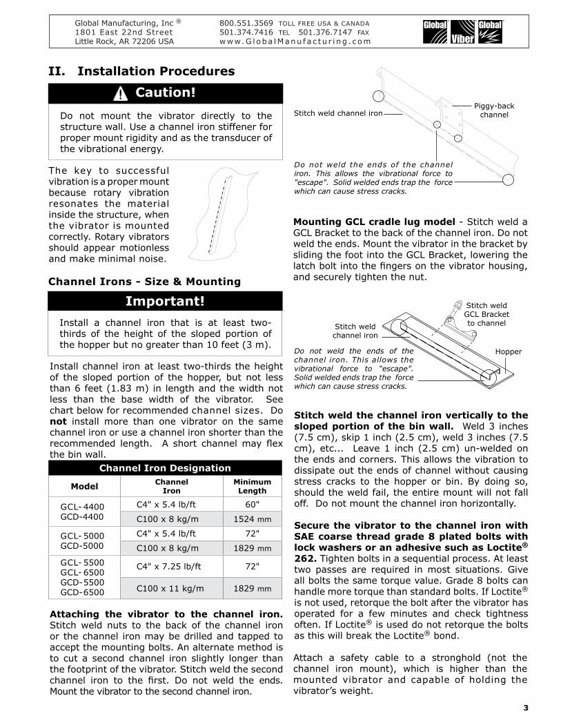
Do not mount the vibrator directly to the structure wall Use a channel iron stiffener for proper mount rigidity and as the transducer of the vibrational energy
Channel Irons - Size amp Mounting
Install channel iron at least two-thirds the height of the sloped portion of the hopper but not less than 6 feet (183 m) in length and the width not less than the base width of the vibrator See chart below for recommended channel sizes Do not install more than one vibrator on the same channel iron or use a channel iron shorter than the recommended length A short channel may flex the bin wall
Attaching the vibrator to the channel iron Stitch weld nuts to the back of the channel iron or the channel iron may be drilled and tapped to accept the mounting bolts An alternate method is to cut a second channel iron slightly longer than the footprint of the vibrator Stitch weld the second channel iron to the first Do not weld the ends Mount the vibrator to the second channel iron
Stitch weld the channel iron vertically to the sloped portion of the bin wall Weld 3 inches (75 cm) skip 1 inch (25 cm) weld 3 inches (75 cm) etc Leave 1 inch (25 cm) un-welded on the ends and corners This allows the vibration to dissipate out the ends of channel without causing stress cracks to the hopper or bin By doing so should the weld fail the entire mount will not fall off Do not mount the channel iron horizontally
Secure the vibrator to the channel iron with SAE coarse thread grade 8 plated bolts with lock washers or an adhesive such as Loctitereg 262 Tighten bolts in a sequential process At least two passes are required in most situations Give all bolts the same torque value Grade 8 bolts can handle more torque than standard bolts If Loctitereg
is not used retorque the bolt after the vibrator has operated for a few minutes and check tightness often If Loctitereg is used do not retorque the bolts as this will break the Loctitereg bond
Attach a safety cable to a stronghold (not the channel iron mount) which is higher than the mounted vibrator and capable of holding the vibratorrsquos weight
Install a channel iron that is at least two-thirds of the height of the sloped portion of the hopper but no greater than 10 feet (3 m)
Important
Caution
Mounting GCL cradle lug model - Stitch weld a GCL Bracket to the back of the channel iron Do not weld the ends Mount the vibrator in the bracket by sliding the foot into the GCL Bracket lowering the latch bolt into the fingers on the vibrator housing and securely tighten the nut
Piggy-back channelStitch weld channel iron
Do not weld the ends of the channel iron This allows the vibrational force to escape Solid welded ends trap the force which can cause stress cracks
Stitch weld channel iron
Do not weld the ends of the channel iron This allows the vibrational force to ldquoescaperdquo Solid welded ends trap the force which can cause stress cracks
Hopper
Stitch weld GCL Bracketto channel
Channel Iron Designation
Model ChannelIron
Minimum Length
GCL- 4400 GCD-4400
C4 x 54 lbft 60
C100 x 8 kgm 1524 mm
GCL- 5000 GCD-5000
C4 x 54 lbft 72
C100 x 8 kgm 1829 mm
GCL- 5500 GCL- 6500GCD- 5500 GCD- 6500
C4 x 725 lbft 72
C100 x 11 kgm 1829 mm
Global Manufacturing Inc reg 8005513569 TOLL FREE USA amp CANADA1801 East 22nd Street 5013747416 TEL 5013767147 FAXLittle Rock AR 72206 USA wwwG l oba lManu f a c t u r i ng c om
4
III Mounting Locations
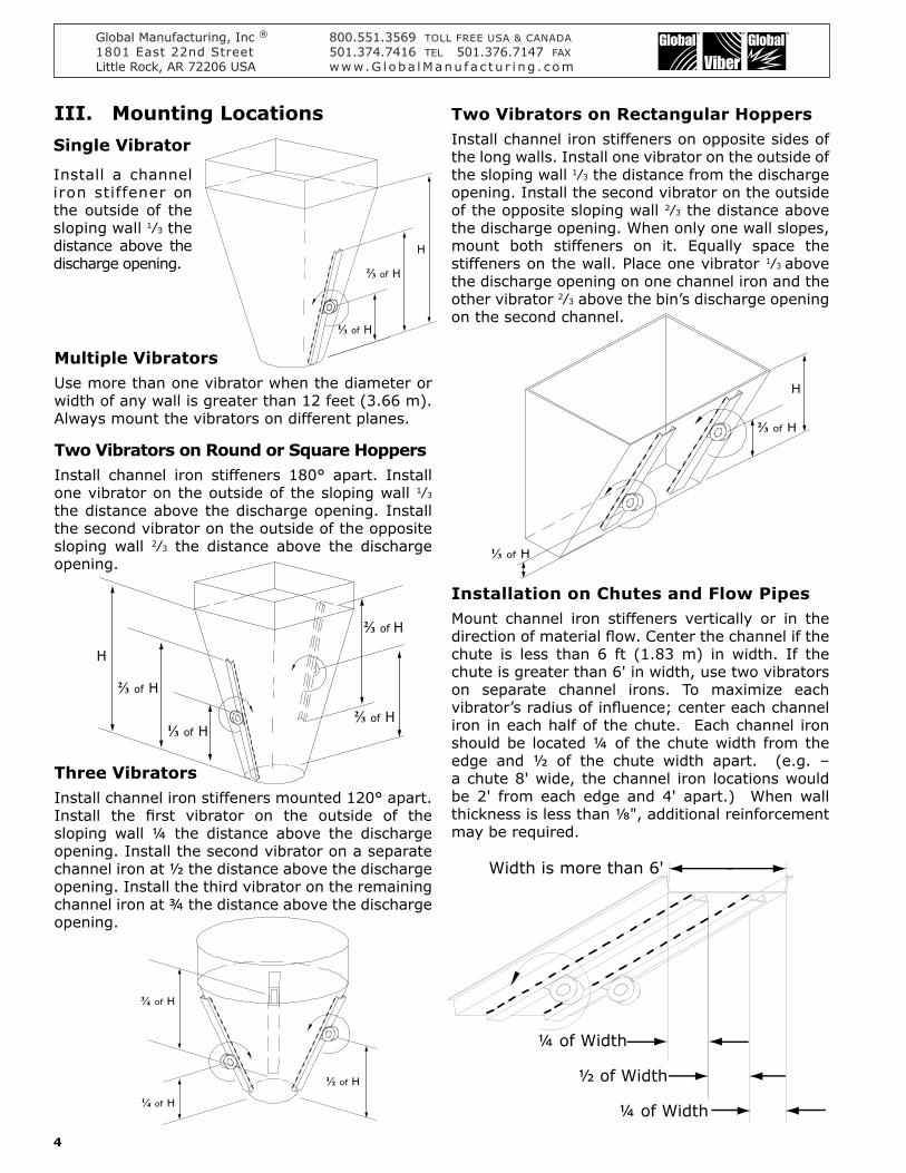
Install a channel iron stiffener on the outside of the sloping wall 1frasl3 the distance above the discharge opening
Multiple VibratorsUse more than one vibrator when the diameter or width of any wall is greater than 12 feet (366 m) Always mount the vibrators on different planes
Two Vibrators on Round or Square HoppersInstall channel iron stiffeners 180deg apart Install one vibrator on the outside of the sloping wall 1frasl3 the distance above the discharge opening Install the second vibrator on the outside of the opposite sloping wall 2frasl3 the distance above the discharge opening
Two Vibrators on Rectangular Hoppers Install channel iron stiffeners on opposite sides of the long walls Install one vibrator on the outside of the sloping wall 1frasl3 the distance from the discharge opening Install the second vibrator on the outside of the opposite sloping wall 2frasl3 the distance above the discharge opening When only one wall slopes mount both stiffeners on it Equally space the stiffeners on the wall Place one vibrator 1frasl3 above the discharge opening on one channel iron and the other vibrator 2frasl3 above the binrsquos discharge opening on the second channel
Three VibratorsInstall channel iron stiffeners mounted 120deg apart Install the first vibrator on the outside of the sloping wall frac14 the distance above the discharge opening Install the second vibrator on a separate channel iron at frac12 the distance above the discharge opening Install the third vibrator on the remaining channel iron at frac34 the distance above the discharge opening
Installation on Chutes and Flow PipesMount channel iron stiffeners vertically or in the direction of material flow Center the channel if the chute is less than 6 ft (183 m) in width If the chute is greater than 6 in width use two vibrators on separate channel irons To maximize each vibratorrsquos radius of influence center each channel iron in each half of the chute Each channel iron should be located frac14 of the chute width from the edge and frac12 of the chute width apart (eg ndash a chute 8 wide the channel iron locations would be 2 from each edge and 4 apart) When wall thickness is less than ⅛ additional reinforcement may be required
H
⅓ of H
⅔ of H
⅓ of H
⅔ of H
H
frac34 of H
frac14 of H
frac12 of H
⅔ of H
⅓ of H
⅔ of H
⅔ of H
H
Width is more than 6
frac14 of Width
frac12 of Width
frac14 of Width
Single Vibrator
Global Manufacturing Inc reg 8005513569 TOLL FREE USA amp CANADA1801 East 22nd Street 5013747416 TEL 5013767147 FAXLittle Rock AR 72206 USA wwwG l oba lManu f a c t u r i ng c om
5
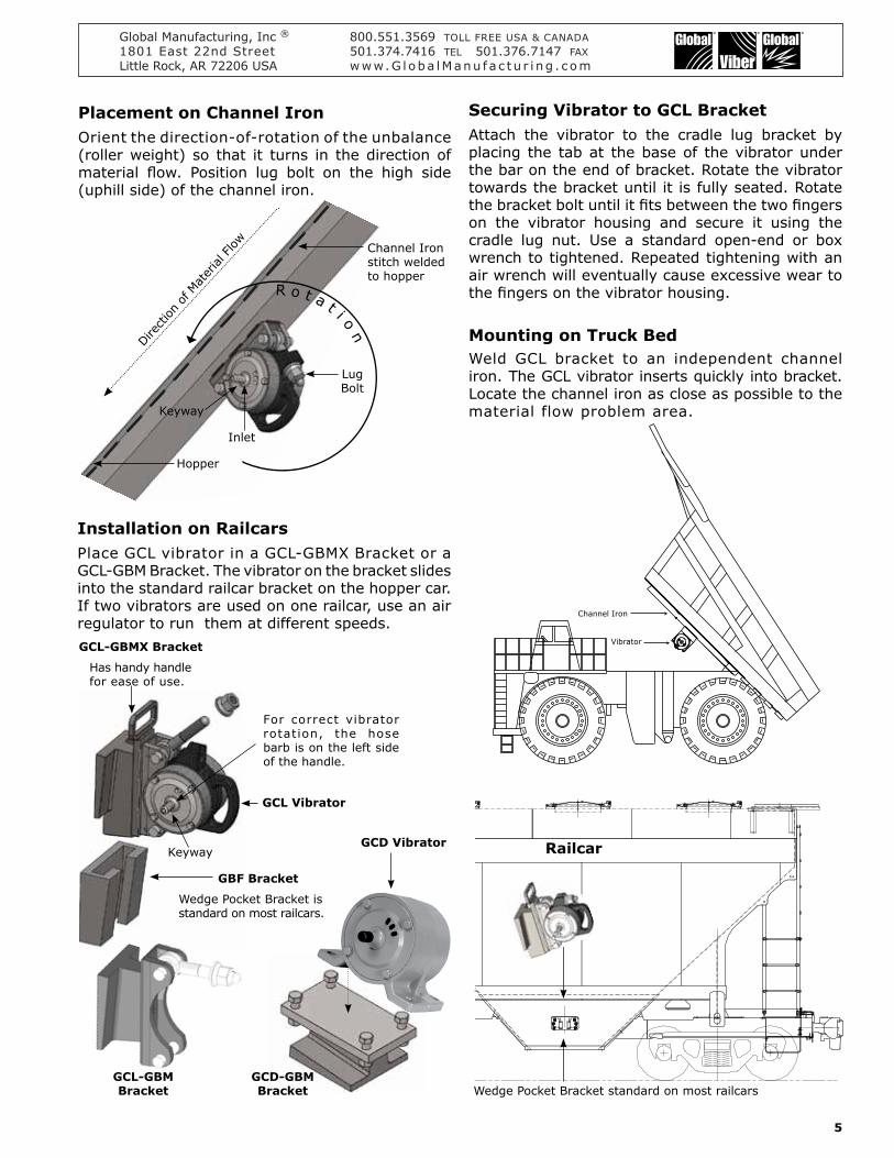
Installation on RailcarsPlace GCL vibrator in a GCL-GBMX Bracket or a GCL-GBM Bracket The vibrator on the bracket slides into the standard railcar bracket on the hopper car If two vibrators are used on one railcar use an air regulator to run them at different speeds
Placement on Channel IronOrient the direction-of-rotation of the unbalance (roller weight) so that it turns in the direction of material flow Position lug bolt on the high side (uphill side) of the channel iron
Mounting on Truck BedWeld GCL bracket to an independent channel iron The GCL vibrator inserts quickly into bracket Locate the channel iron as close as possible to the material flow problem area
Securing Vibrator to GCL BracketAttach the vibrator to the cradle lug bracket by placing the tab at the base of the vibrator under the bar on the end of bracket Rotate the vibrator towards the bracket until it is fully seated Rotate the bracket bolt until it fits between the two fingers on the vibrator housing and secure it using the cradle lug nut Use a standard open-end or box wrench to tightened Repeated tightening with an air wrench will eventually cause excessive wear to the fingers on the vibrator housing
Vibrator
Channel Iron
Railcar
Wedge Pocket Bracket standard on most railcars
R o t a t i on
Hopper
Inlet
Channel Ironstitch weldedto hopper
Keyway
LugBolt
Dire
ction
of M
ater
ial Flow
GCL-GBM Bracket
GCD-GBM Bracket
For correct vibrator rotation the hose barb is on the left side of the handle
GCL Vibrator
GCD Vibrator
GCL-GBMX Bracket
Has handy handle for ease of use
GBF Bracket
Wedge Pocket Bracket is standard on most railcars
Keyway
Global Manufacturing Inc reg 8005513569 TOLL FREE USA amp CANADA1801 East 22nd Street 5013747416 TEL 5013767147 FAXLittle Rock AR 72206 USA wwwG l oba lManu f a c t u r i ng c om
6
IV OperationGlobal High Frequency External Vibrators are pneumatic with dual rollers Their ease of operation and low maintenance is due in part to the fact that these vibrators contain no bearings or motors
The vibrator may run continuously at speeds up to the rated running conditions shown in our performance data Use a ball valve or solenoid valve to turn the vibrator on and off A regulator provides constant speed control even as the plant air pressure varies
Install a filter regulator gauge and lubricator in the air line within 10 to 12 feet (3 - 37 m)
FiltrationDo not connect the vibrator directly to plant air Use a 64 micron filter Drain the airline filter regularly and examine the element for signs of clogging
Regulation
Operate the vibrator on filtered regulated lubricated air between 40 - 80 psi (28 - 55 bar) at 45 - 60 cfm (21 - 28 Lps)
LubricationUse a lightweight lubricant Replenish the airline lubricator as required and set to give the following drop rate minimum Will operate in temperatures of 32deg F (0deg C) to 250deg F (120deg C)
Filter amp Lubrication Requirements
Filtration Required Lubrication Required
64 Micron 10 -1 2 Drops per Minute10 Weight Oil
Recommended Lubricants Shell Tellus 37BP Energol HL65Castrol Hyspin 70Mobil Alma oil No 1
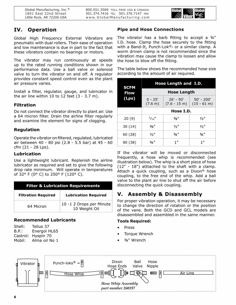
Pipe and Hose Connections
The vibrator has a barb fitting to accept a frac34 ID hose Clamp the hose securely to the fitting with a Band-It Punch-Lokreg or a similar clamp A worm driven clamp is not recommended since the vibration may cause the clamp to loosen and allow the hose to blow off the fitting
The table below shows the recommended hose size according to the amount of air required
SCFM Flow(Lps)
Hose Length and ID
Hose Length
0 - 25(76 m)
26 - 50(76 - 15 m)
50 - 200(15 - 61 m)
Hose ID
20 (9) 5frasl16 ⅜ frac12
30 (14) ⅜ frac12 frac12
60 (28) frac12 frac34 frac34
80 (38) frac34 1 1
If the vibrator will be moved or disconnected frequently a hose whip is recommended (see illustration below) The whip is a short piece of hose (12 - 18) atttached to the shaft with a clamp Attach a quick coupling such as a Dixonreg hose coupling to the free end of the whip Add a ball valve to the plant air line to shut off the air before disconnecting the quick coupling
V Assembly amp DisassemblyFor proper vibration operation it may be necessary to change the direction of rotation or the position of the vane Both the GCD and GCL models are disassembled and assembled in the same mannerTools Requiredbull Pressbull Torque Wrenchbull ⅜ Wrench
Vibrator Punch-loksreg = DixonHose Ends
HoseNipple
BallValve
Air LineHose Whip
Hose Whip Assemblypart number 260197
Global Manufacturing Inc reg 8005513569 TOLL FREE USA amp CANADA1801 East 22nd Street 5013747416 TEL 5013767147 FAXLittle Rock AR 72206 USA wwwG l oba lManu f a c t u r i ng c om
7
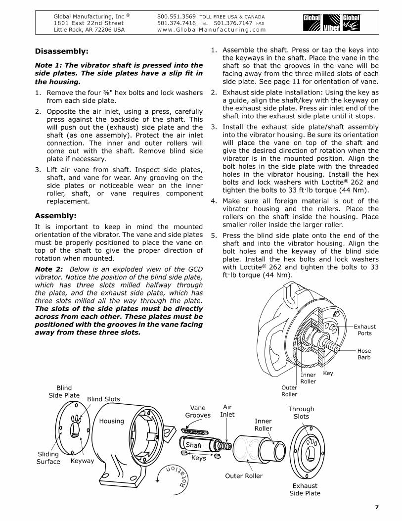
Disassembly
Note 1 The vibrator shaft is pressed into the side plates The side plates have a slip fit in the housing 1 Remove the four ⅜ hex bolts and lock washers
from each side plate2 Opposite the air inlet using a press carefully
press against the backside of the shaft This will push out the (exhaust) side plate and the shaft (as one assembly) Protect the air inlet connection The inner and outer rollers will come out with the shaft Remove blind side plate if necessary
3 Lift air vane from shaft Inspect side plates shaft and vane for wear Any grooving on the side plates or noticeable wear on the inner roller shaft or vane requires component replacement
Assembly It is important to keep in mind the mounted orientation of the vibrator The vane and side plates must be properly positioned to place the vane on top of the shaft to give the proper direction of rotation when mountedNote 2 Below is an exploded view of the GCD vibrator Notice the position of the blind side plate which has three slots milled halfway through the plate and the exhaust side plate which has three slots milled all the way through the plate The slots of the side plates must be directly across from each other These plates must be positioned with the grooves in the vane facing away from these three slots
1 Assemble the shaft Press or tap the keys into the keyways in the shaft Place the vane in the shaft so that the grooves in the vane will be facing away from the three milled slots of each side plate See page 11 for orientation of vane
2 Exhaust side plate installation Using the key as a guide align the shaftkey with the keyway on the exhaust side plate Press air inlet end of the shaft into the exhaust side plate until it stops
3 Install the exhaust side plateshaft assembly into the vibrator housing Be sure its orientation will place the vane on top of the shaft and give the desired direction of rotation when the vibrator is in the mounted position Align the bolt holes in the side plate with the threaded holes in the vibrator housing Install the hex bolts and lock washers with Loctitereg 262 and tighten the bolts to 33 ftlb torque (44 Nm)
4 Make sure all foreign material is out of the vibrator housing and the rollers Place the rollers on the shaft inside the housing Place smaller roller inside the larger roller
5 Press the blind side plate onto the end of the shaft and into the vibrator housing Align the bolt holes and the keyway of the blind side plate Install the hex bolts and lock washers with Loctitereg 262 and tighten the bolts to 33 ftlb torque (44 Nm)
Outer Roller
Blind Slots
BlindSide Plate
SlidingSurface Keyway Keys
ExhaustSide Plate
InnerRoller
Shaft
AirInlet
Housing
VaneGrooves
ThroughSlots
Ro
ta
tion
Vane
InnerRoller
Key
HoseBarb
OuterRoller
ExhaustPorts
Global Manufacturing Inc reg 8005513569 TOLL FREE USA amp CANADA1801 East 22nd Street 5013747416 TEL 5013767147 FAXLittle Rock AR 72206 USA wwwG l oba lManu f a c t u r i ng c om
8
VI Vibrating Wet Concrete
Concrete Consolidation by vibration is achieved by adding a mechanically-induced combination of force and frequency allowing those forces to act on the freshly-poured concrete within the vibrators area of influence The proper combination of force and frequency will ensure that the concrete will retain its homogeneity while allowing the entrapped air to escape through the surface A frequency of 9000 ndash 12000 vibrations per minute initiates resonance in (or ldquoexcitesrdquo) the cement causing the ultra-fine cement particles to release the extremely small air pockets that have adhered to the cement so that the mortar fills in all of the spaces around the aggregate Vibration evenly distributes the cement and aggregates resulting in a more dense and a smoother concrete finish
When enough of the entrapped air has risen to the surface to achieve concrete consistent with the intended strength of the mixture the vibration is complete In practical terms it is neither possible nor necessary to remove all of the entrapped air in the consolidation process
How to Select an External Vibrator
There is not an exact method or science when using external vibrators for concrete consolidation Mixes vary and therefore consolidation procedures and preferred vibrator styles vary ldquoExpertsrdquo become experts through trial and error What makes every application different is that the mixes will vary due to the slump any chemical additives aggregate sizesshape cement content consistency of the mixture weather conditions and even the type of form work used Following these general rules may be helpful in selecting the number and placement of external vibrators for effective concrete consoli-dation
In selecting External Vibrators the contractor should initially consider the workability of the concrete and the rigidity of the forms Plastic concrete (slump gt 3) responds better to high frequency vibration while stiffer mixtures (slump lt 3) require higher amplitude vibration to initiate fluidization While properly-sized external vibrators can be successfully used on virtually any concrete formwork using a too-powerful vibrator on lightweight forms can cause damage to the formwork This has caused some contractors to mistakenly believe that external vibrators cannot be used on lightweight concrete formwork
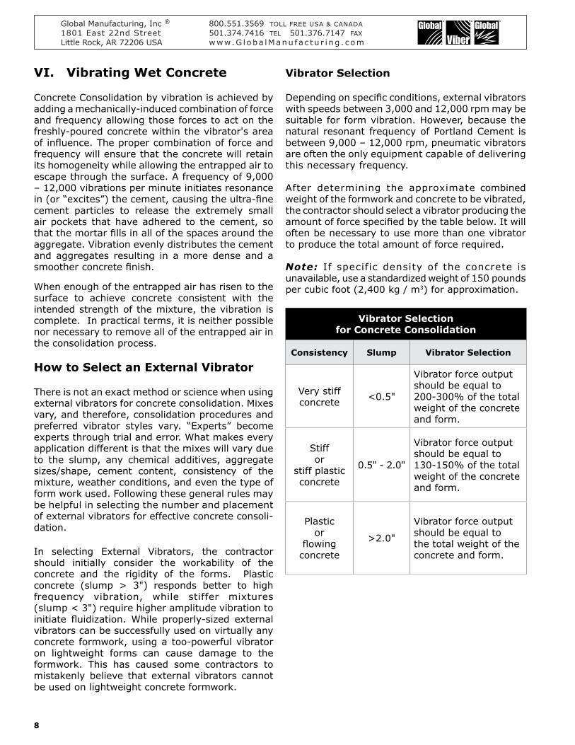
Vibrator Selection
Depending on specific conditions external vibrators with speeds between 3000 and 12000 rpm may be suitable for form vibration However because the natural resonant frequency of Portland Cement is between 9000 ndash 12000 rpm pneumatic vibrators are often the only equipment capable of delivering this necessary frequency
After determining the approximate combined weight of the formwork and concrete to be vibrated the contractor should select a vibrator producing the amount of force specified by the table below It will often be necessary to use more than one vibrator to produce the total amount of force required
Note If specific density of the concrete is unavailable use a standardized weight of 150 pounds per cubic foot (2400 kg m3) for approximation
Vibrator Selectionfor Concrete Consolidation
Consistency Slump Vibrator Selection
Very stiff concrete lt05
Vibrator force output should be equal to 200-300 of the total weight of the concrete and form
Stiff or
stiff plastic concrete
05 - 20
Vibrator force output should be equal to 130-150 of the total weight of the concrete and form
Plastic or
flowing concrete
gt20
Vibrator force output should be equal to the total weight of the concrete and form
Global Manufacturing Inc reg 8005513569 TOLL FREE USA amp CANADA1801 East 22nd Street 5013747416 TEL 5013767147 FAXLittle Rock AR 72206 USA wwwG l oba lManu f a c t u r i ng c om
9
Tips for using External Vibrators for concrete consolidation
Proper placement of the external vibrators is critical to ensure that the vibration is distributed over the desired area of the concrete Depending on the concrete consistency density of embedments and the quality of the mounting External Vibrators produce an Area-of-Influence determined by the force and frequency of the vibrator and the duration of the vibrating time
The following guidelines for spacing External Vibrators have been developed but contractors should determine specific spacing requirements for each project to ensure complete coverage of vibration and successful consolidation
Vibrator Spacing for Concrete Consolidation
Consistency SlumpDistance between
Vibrators
Very stiff or stiff concrete
lt 10lt 25 mm
5 Apart1524 mm
Stiff plastic concrete
10 minus 2025 minus 50 mm
6 Apart1828 mm
Plastic concrete
20 minus 5050 minus 127 mm
7 Apart2134 mm
Flowing concrete
gt 50gt 127 mm
8 Apart 2438 mm
Vibrating times for external vibrators may be longer than for immersed internal vibrators Most operators will initially vibrate for approximately two minutes per lift and increase or decrease vibrating times as needed Note that the same criteria should be used to determine when the consolidation is complete (no air bubbles at the top surface a thin film of mortar on the top surface and a stabilization of the speed of the vibrator)
Pour concrete into the forms in evenly dispersed layers (lifts) Do not exceed a 20 lift height otherwise the weight of the concrete can prevent the entrapped air from escaping Operate vibrators in conjunction with each lift until the concrete is fully consolidated As each subsequent lift is placed locate additional vibrators for operation (or move them from the previous level) Some operators prefer to operate the previous liftrsquos vibrators for a short period of time to promote ldquoknittingrdquo of the two layers together
Important
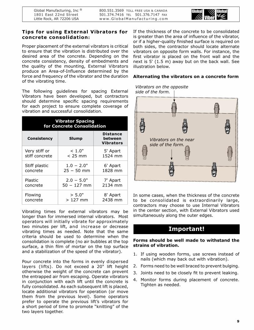
If the thickness of the concrete to be consolidated is greater than the area of influence of the vibrator or if a higher-quality finished surface is required on both sides the contractor should locate alternate vibrators on opposite form walls For instance the first vibrator is placed on the front wall and the next is 5 (15 m) away but on the back wall See illustration below
Alternating the vibrators on a concrete form
In some cases when the thickness of the concrete to be consolidated is extraordinarily large contractors may choose to use Internal Vibrators in the center section with External Vibrators used simultaneously along the outer edges
Forms should be well made to withstand the strains of vibration
1 If using wooden forms use screws instead of nails (which may back out with vibration)
2 Forms need to be well braced to prevent bulging3 Joints need to be closely fit to prevent leaking4 Monitor forms during placement of concrete
Tighten as needed
Vibrators on the opposite side of the form
Vibrators on the near side of the form
Global Manufacturing Inc reg 8005513569 TOLL FREE USA amp CANADA1801 East 22nd Street 5013747416 TEL 5013767147 FAXLittle Rock AR 72206 USA wwwG l oba lManu f a c t u r i ng c om
10
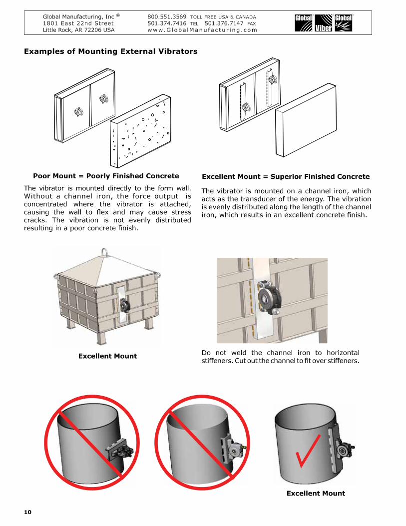
Examples of Mounting External Vibrators
The vibrator is mounted directly to the form wall Without a channel iron the force output is concentrated where the vibrator is attached causing the wall to flex and may cause stress cracks The vibration is not evenly distributed resulting in a poor concrete finish
The vibrator is mounted on a channel iron which acts as the transducer of the energy The vibration is evenly distributed along the length of the channel iron which results in an excellent concrete finish
Excellent Mount
Excellent Mount Do not weld the channel iron to horizontal stiffeners Cut out the channel to fit over stiffeners
Poor Mount = Poorly Finished Concrete Excellent Mount = Superior Finished Concrete
Global Manufacturing Inc reg 8005513569 TOLL FREE USA amp CANADA1801 East 22nd Street 5013747416 TEL 5013767147 FAXLittle Rock AR 72206 USA wwwG l oba lManu f a c t u r i ng c om
11
Assembly Table
Vane
Hose Barb
Hopper
MaterialFlow Key
Plan View
Assembly Table
Plan View
Assembly Table
Plan View
Assembly Table
Plan View
Direction of Rotation
Direction of Rotation
Direction of Rotation
Direction of Rotation
Hopper
MaterialFlow
Vane
Key
Hose Barb
Air bubblesrise to thesurface
Concrete FormHose Barb
Hose BarbVa
ne
Vane
Key
Key Air bubblesrise to thesurface
Concrete Form
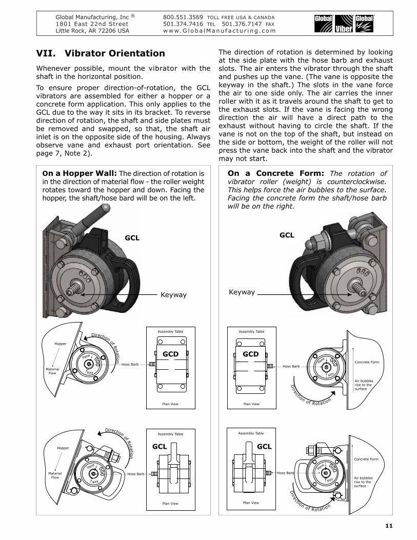
On a Concrete Form The rotation of vibrator roller (weight) is counterclockwise This helps force the air bubbles to the surface Facing the concrete form the shafthose barb will be on the right
On a Hopper Wall The direction of rotation is in the direction of material flow - the roller weight rotates toward the hopper and down Facing the hopper the shafthose bard will be on the left
GCD GCD
GCLGCL
Keyway
GCL GCL
Keyway
VII Vibrator OrientationWhenever possible mount the vibrator with the shaft in the horizontal positionTo ensure proper direction-of-rotation the GCL vibrators are assembled for either a hopper or a concrete form application This only applies to the GCL due to the way it sits in its bracket To reverse direction of rotation the shaft and side plates must be removed and swapped so that the shaft air inlet is on the opposite side of the housing Always observe vane and exhaust port orientation See page 7 Note 2)
The direction of rotation is determined by looking at the side plate with the hose barb and exhaust slots The air enters the vibrator through the shaft and pushes up the vane (The vane is opposite the keyway in the shaft) The slots in the vane force the air to one side only The air carries the inner roller with it as it travels around the shaft to get to the exhaust slots If the vane is facing the wrong direction the air will have a direct path to the exhaust without having to circle the shaft If the vane is not on the top of the shaft but instead on the side or bottom the weight of the roller will not press the vane back into the shaft and the vibrator may not start
Global Manufacturing Inc reg 8005513569 TOLL FREE USA amp CANADA1801 East 22nd Street 5013747416 TEL 5013767147 FAXLittle Rock AR 72206 USA wwwG l oba lManu f a c t u r i ng c om
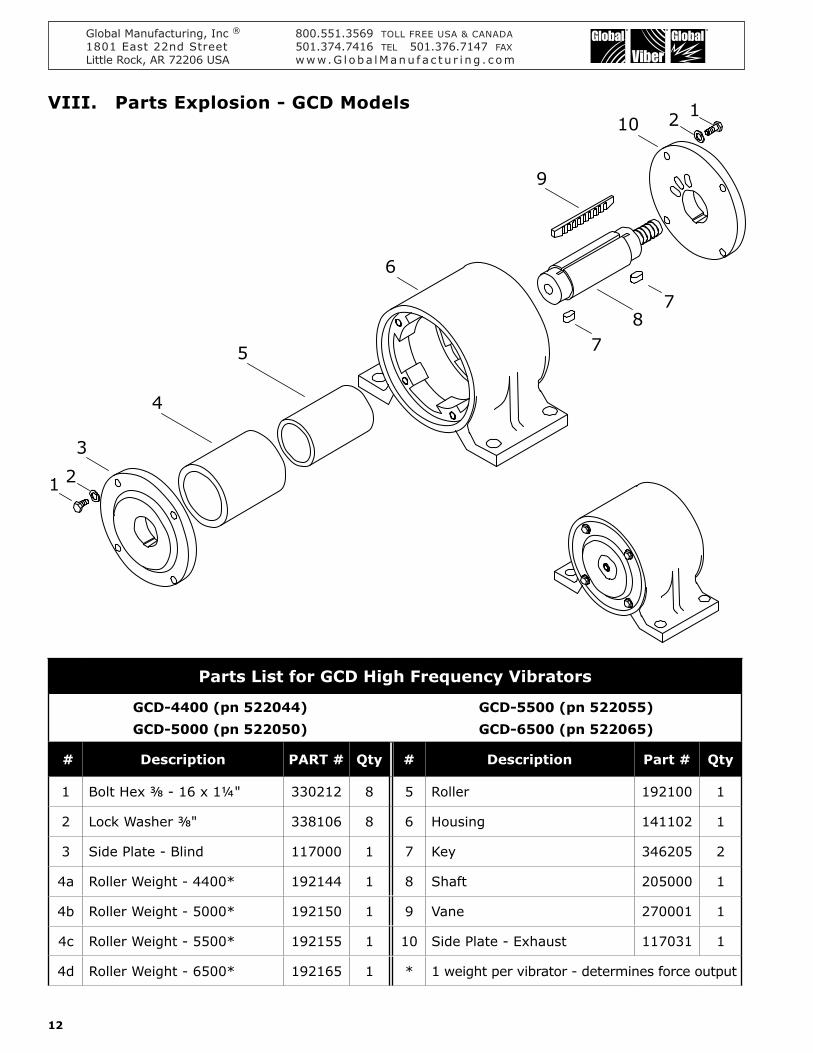
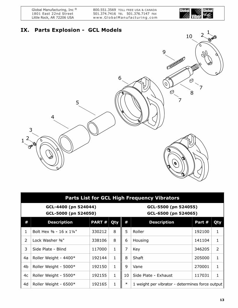
4d Roller Weight - 6500 192165 1 1 weight per vibrator - determines force output
1 2
12
3
4
5
6
9
8
10
7
7
VIII Parts Explosion - GCD Models
Global Manufacturing Inc reg 8005513569 TOLL FREE USA amp CANADA1801 East 22nd Street 5013747416 TEL 5013767147 FAXLittle Rock AR 72206 USA wwwG l oba lManu f a c t u r i ng c om
4d Roller Weight - 6500 192165 1 1 weight per vibrator - determines force output
1 2
12
3
4
5
6
9
8
10
7
7
IX Parts Explosion - GCL Models
Global Manufacturing Inc reg 8005513569 TOLL FREE USA amp CANADA1801 East 22nd Street 5013747416 TEL 5013767147 FAXLittle Rock AR 72206 USA wwwG l oba lManu f a c t u r i ng c om
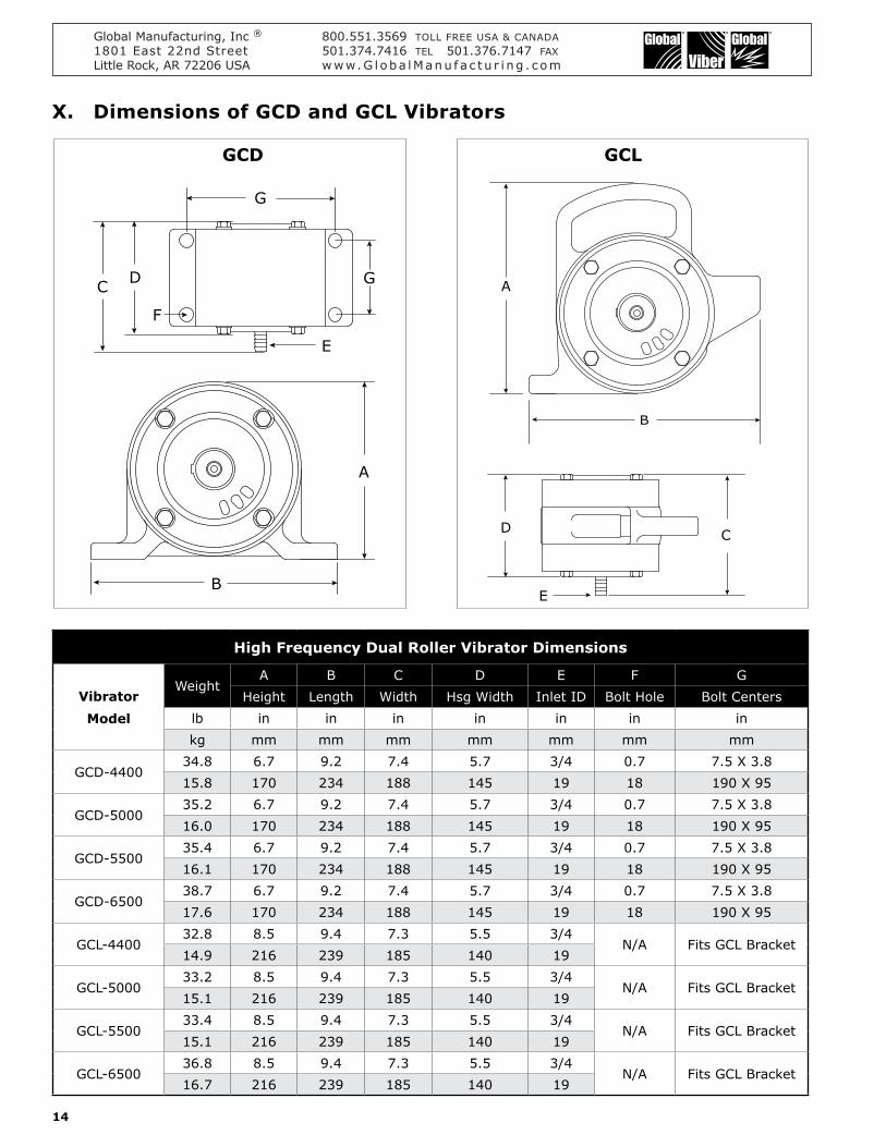
14
High Frequency Dual Roller Vibrator Dimensions
VibratorModel
WeightA B C D E F G
Height Length Width Hsg Width Inlet ID Bolt Hole Bolt Centerslb in in in in in in inkg mm mm mm mm mm mm mm
GCD-4400348 67 92 74 57 34 07 75 X 38158 170 234 188 145 19 18 190 X 95
GCD-5000352 67 92 74 57 34 07 75 X 38160 170 234 188 145 19 18 190 X 95
GCD-5500354 67 92 74 57 34 07 75 X 38161 170 234 188 145 19 18 190 X 95
GCD-6500387 67 92 74 57 34 07 75 X 38176 170 234 188 145 19 18 190 X 95
GCL-4400328 85 94 73 55 34
NA Fits GCL Bracket149 216 239 185 140 19
GCL-5000332 85 94 73 55 34
NA Fits GCL Bracket151 216 239 185 140 19
GCL-5500334 85 94 73 55 34
NA Fits GCL Bracket151 216 239 185 140 19
GCL-6500368 85 94 73 55 34
NA Fits GCL Bracket167 216 239 185 140 19
X Dimensions of GCD and GCL Vibrators
GCD GCL
A
D C
B
E
DC
G
G
E
F
A
B
Global Manufacturing Inc reg 8005513569 TOLL FREE USA amp CANADA1801 East 22nd Street 5013747416 TEL 5013767147 FAXLittle Rock AR 72206 USA wwwG l oba lManu f a c t u r i ng c om
15
600152 mm
C
500127 mm
D
925 532 mmB
650 561 mm
37595 mm
A
7001778 mm
B
226574 mm
65016510 mm
D
124315 mm
77519685 mm
C
2997595 mm
A
511295 mm
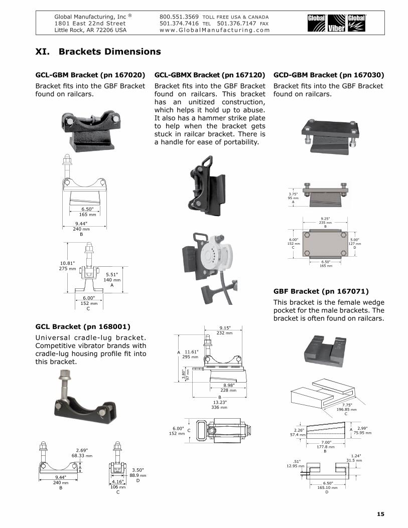
XI Brackets Dimensions
944240 mm
B
350889 mm
D416106 mm
C
A
2696833 mm
551140 mm
A
944240 mm
B
1081275 mm
650165 mm
600152 mm
C
B
915232 mm
380
97
mm
1161295 mm
898228 mm
1323336 mm
600152 mm
C
A
GCL-GBM Bracket (pn 167020)Bracket fits into the GBF Bracket found on railcars
GCD-GBM Bracket (pn 167030)Bracket fits into the GBF Bracket found on railcars
GCL Bracket (pn 168001)Universal cradle-lug bracket Competitive vibrator brands with cradle-lug housing profile fit into this bracket
GBF Bracket (pn 167071)This bracket is the female wedge pocket for the male brackets The bracket is often found on railcars
GCL-GBMX Bracket (pn 167120)Bracket fits into the GBF Bracket found on railcars This bracket has an unitized construction which helps it hold up to abuse It also has a hammer strike plate to help when the bracket gets stuck in railcar bracket There is a handle for ease of portability
Global Manufacturing Inc reg 8005513569 TOLL FREE USA amp CANADA1801 East 22nd Street 5013747416 TEL 5013767147 FAXLittle Rock AR 72206 USA wwwG l oba lManu f a c t u r i ng c om
16
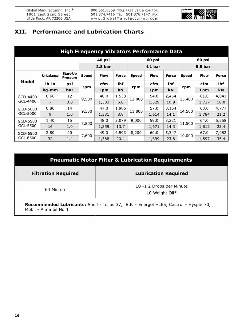
Pneumatic Motor Filter amp Lubrication Requirements
Filtration Required Lubrication Required
64 Micron10 -1 2 Drops per Minute
10 Weight Oil
Recommended Lubricants Shell - Tellus 37 BP - Energol HL65 Castrol - Hyspin 70 Mobil - Alma oil No 1
High Frequency Vibrators Performance Data40 psi 60 psi 80 psi
28 bar 41 bar 55 bar
ModelUnbalance Start-Up
Pressure Speed Flow Force Speed Flow Force Speed Flow Force
lb-in psirpm
cfm lbfrpm
cfm lbfrpm
cfm lbfkg-mm bar Lpm kN Lpm kN Lpm kN
GCD-4400 GCL-4400
060 129500
460 153812000
540 245415400
610 40417 08 1303 68 1529 109 1727 180
GCD-5000 GCL-5000
080 149350
470 198611800
570 316414500
630 47779 10 1331 88 1614 141 1784 212
GCD-5500 GCL-5500
140 158800
480 3079 9000 590 322111500
640 525816 10 1359 137 1671 143 1812 234
GCD-6500 GCL-6500
280 207600
490 4593 8200 600 534710000
670 795232 14 1388 204 1699 238 1897 354
XII Performance and Lubrication Charts
Global Manufacturing Inc reg 8005513569 TOLL FREE USA amp CANADA1801 East 22nd Street 5013747416 TEL 5013767147 FAXLittle Rock AR 72206 USA wwwG l oba lManu f a c t u r i ng c om
17
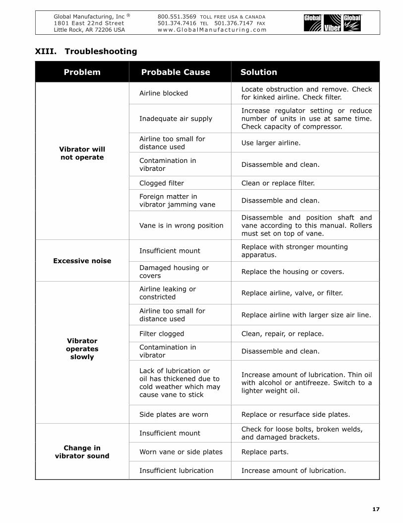
Problem Probable Cause Solution
Vibrator will not operate
Airline blocked Locate obstruction and remove Check for kinked airline Check filter
Inadequate air supplyIncrease regulator setting or reduce number of units in use at same time Check capacity of compressor
Airline too small for distance used Use larger airline
Contamination in vibrator Disassemble and clean
Clogged filter Clean or replace filter
Foreign matter in vibrator jamming vane Disassemble and clean
Vane is in wrong positionDisassemble and position shaft and vane according to this manual Rollers must set on top of vane
Excessive noiseInsufficient mount Replace with stronger mounting
apparatus
Damaged housing or covers Replace the housing or covers
Vibrator operates slowly
Airline leaking or constricted Replace airline valve or filter
Airline too small for distance used Replace airline with larger size air line
Filter clogged Clean repair or replace
Contamination in vibrator Disassemble and clean
Lack of lubrication or oil has thickened due to cold weather which may cause vane to stick
Increase amount of lubrication Thin oil with alcohol or antifreeze Switch to a lighter weight oil
Side plates are worn Replace or resurface side plates
Change invibrator sound
Insufficient mount Check for loose bolts broken welds and damaged brackets
Worn vane or side plates Replace parts
Insufficient lubrication Increase amount of lubrication
XIII Troubleshooting
High Frequency Vibrators Performance Data40 psi 60 psi 80 psi
28 bar 41 bar 55 bar
ModelUnbalance Start-Up
Pressure Speed Flow Force Speed Flow Force Speed Flow Force
lb-in psirpm
cfm lbfrpm
cfm lbfrpm
cfm lbfkg-mm bar Lpm kN Lpm kN Lpm kN
GCD-4400 GCL-4400
060 129500
460 153812000
540 245415400
610 40417 08 1303 68 1529 109 1727 180
GCD-5000 GCL-5000
080 149350
470 198611800
570 316414500
630 47779 10 1331 88 1614 141 1784 212
GCD-5500 GCL-5500
140 158800
480 3079 9000 590 322111500
640 525816 10 1359 137 1671 143 1812 234
GCD-6500 GCL-6500
280 207600
490 4593 8200 600 534710000
670 795232 14 1388 204 1699 238 1897 354
Global Manufacturing Inc reg 8005513569 TOLL FREE USA amp CANADA1801 East 22nd Street 5013747416 TEL 5013767147 FAXLittle Rock AR 72206 USA wwwG l oba lManu f a c t u r i ng c om
2
Table of Contents PageI Introduction 2
II Installation Procedures 3
III Mounting 4 - 5
IV Operation 6
V Assembly amp Disassembly Procedures 6 - 7
VI Vibrating Wet Concrete 8 - 10
VII Vibrator Orientation 11
VIII Parts Explosion - GCD 12
IX Parts Explosion - GCL 13
X Vibrator Dimensions - GCD amp GCL 14
XI Bracket Dimensions 15
XII Performance Data amp Lubrication 16
XIII Troubleshooting 17
I IntroductionYou have purchased a GCL-4400GCD-4400 GCL-5000GCD-5000 GCL-5500GCD-5500 or GCL-6500GCD-6500 High Frequency vibrator manufactured by Global Manufacturing Increg They are excellent roller style high frequency pneumatic vibrators used on forms for concrete consolidation The GCL model fits the standard cradle lug brackets commonly used on concrete forms The GCD models are bolt-on for a more permanent mount although they can also be attached to portable brackets
For optimum performance cycle the vibrator on and off Vibrator act as a friction reducer and once the bulk solid is set into motion gravity does the rest Do not operate the vibrator on an empty hopper as this may cause structural damage to the hopper Operate vibrators only when discharge gates are open Vibration will compact the material inside the structure if the discharge gate is closed
Vibration has two important elements ndash Frequency and Amplitude Frequency is the speed (RPM) or the number of vibrations per minute It is controlled by the air flow to a pneumatic vibrator Amplitude is the unbalance or amount of force produced by the eccentric weight The faster the eccentric weights turn the more force output generated Force and frequency work together It is not necessary to use a lot of force when you have adequate frequency
bull Follow all mounting instructions bull Always use a safety cable or chain for support bull Do not operate vibrators when structure is empty bull Do not operate vibrators when gate is closed or conveyor is stopped unless consolidation of material is desired bull Wear ear protection for 90+ decibel levels bull Do not operate the pneumatic vibrators above 100 psibull To prevent explosive hazard do not use combustible gases to drive the pneumatic motorbull Do not use hydrocarbons (fuel or kerosene) as a lubricant or de-icerbull Always operate pneumatic vibrator with a regulator filter and lubricator bull Always disconnect air line before maintenance
SAFETY PRECAUTIONS
Global Manufacturing Inc reg 8005513569 TOLL FREE USA amp CANADA1801 East 22nd Street 5013747416 TEL 5013767147 FAXLittle Rock AR 72206 USA wwwG l oba lManu f a c t u r i ng c om
3
II Installation Procedures
The key to successful vibration is a proper mount because rotary vibration resonates the material inside the structure when the vibrator is mounted correctly Rotary vibrators should appear motionless and make minimal noise
Do not mount the vibrator directly to the structure wall Use a channel iron stiffener for proper mount rigidity and as the transducer of the vibrational energy
Channel Irons - Size amp Mounting
Install channel iron at least two-thirds the height of the sloped portion of the hopper but not less than 6 feet (183 m) in length and the width not less than the base width of the vibrator See chart below for recommended channel sizes Do not install more than one vibrator on the same channel iron or use a channel iron shorter than the recommended length A short channel may flex the bin wall
Attaching the vibrator to the channel iron Stitch weld nuts to the back of the channel iron or the channel iron may be drilled and tapped to accept the mounting bolts An alternate method is to cut a second channel iron slightly longer than the footprint of the vibrator Stitch weld the second channel iron to the first Do not weld the ends Mount the vibrator to the second channel iron
Stitch weld the channel iron vertically to the sloped portion of the bin wall Weld 3 inches (75 cm) skip 1 inch (25 cm) weld 3 inches (75 cm) etc Leave 1 inch (25 cm) un-welded on the ends and corners This allows the vibration to dissipate out the ends of channel without causing stress cracks to the hopper or bin By doing so should the weld fail the entire mount will not fall off Do not mount the channel iron horizontally
Secure the vibrator to the channel iron with SAE coarse thread grade 8 plated bolts with lock washers or an adhesive such as Loctitereg 262 Tighten bolts in a sequential process At least two passes are required in most situations Give all bolts the same torque value Grade 8 bolts can handle more torque than standard bolts If Loctitereg
is not used retorque the bolt after the vibrator has operated for a few minutes and check tightness often If Loctitereg is used do not retorque the bolts as this will break the Loctitereg bond
Attach a safety cable to a stronghold (not the channel iron mount) which is higher than the mounted vibrator and capable of holding the vibratorrsquos weight
Install a channel iron that is at least two-thirds of the height of the sloped portion of the hopper but no greater than 10 feet (3 m)
Important
Caution
Mounting GCL cradle lug model - Stitch weld a GCL Bracket to the back of the channel iron Do not weld the ends Mount the vibrator in the bracket by sliding the foot into the GCL Bracket lowering the latch bolt into the fingers on the vibrator housing and securely tighten the nut
Piggy-back channelStitch weld channel iron
Do not weld the ends of the channel iron This allows the vibrational force to escape Solid welded ends trap the force which can cause stress cracks
Stitch weld channel iron
Do not weld the ends of the channel iron This allows the vibrational force to ldquoescaperdquo Solid welded ends trap the force which can cause stress cracks
Hopper
Stitch weld GCL Bracketto channel
Channel Iron Designation
Model ChannelIron
Minimum Length
GCL- 4400 GCD-4400
C4 x 54 lbft 60
C100 x 8 kgm 1524 mm
GCL- 5000 GCD-5000
C4 x 54 lbft 72
C100 x 8 kgm 1829 mm
GCL- 5500 GCL- 6500GCD- 5500 GCD- 6500
C4 x 725 lbft 72
C100 x 11 kgm 1829 mm
Global Manufacturing Inc reg 8005513569 TOLL FREE USA amp CANADA1801 East 22nd Street 5013747416 TEL 5013767147 FAXLittle Rock AR 72206 USA wwwG l oba lManu f a c t u r i ng c om
4
III Mounting Locations
Install a channel iron stiffener on the outside of the sloping wall 1frasl3 the distance above the discharge opening
Multiple VibratorsUse more than one vibrator when the diameter or width of any wall is greater than 12 feet (366 m) Always mount the vibrators on different planes
Two Vibrators on Round or Square HoppersInstall channel iron stiffeners 180deg apart Install one vibrator on the outside of the sloping wall 1frasl3 the distance above the discharge opening Install the second vibrator on the outside of the opposite sloping wall 2frasl3 the distance above the discharge opening
Two Vibrators on Rectangular Hoppers Install channel iron stiffeners on opposite sides of the long walls Install one vibrator on the outside of the sloping wall 1frasl3 the distance from the discharge opening Install the second vibrator on the outside of the opposite sloping wall 2frasl3 the distance above the discharge opening When only one wall slopes mount both stiffeners on it Equally space the stiffeners on the wall Place one vibrator 1frasl3 above the discharge opening on one channel iron and the other vibrator 2frasl3 above the binrsquos discharge opening on the second channel
Three VibratorsInstall channel iron stiffeners mounted 120deg apart Install the first vibrator on the outside of the sloping wall frac14 the distance above the discharge opening Install the second vibrator on a separate channel iron at frac12 the distance above the discharge opening Install the third vibrator on the remaining channel iron at frac34 the distance above the discharge opening
Installation on Chutes and Flow PipesMount channel iron stiffeners vertically or in the direction of material flow Center the channel if the chute is less than 6 ft (183 m) in width If the chute is greater than 6 in width use two vibrators on separate channel irons To maximize each vibratorrsquos radius of influence center each channel iron in each half of the chute Each channel iron should be located frac14 of the chute width from the edge and frac12 of the chute width apart (eg ndash a chute 8 wide the channel iron locations would be 2 from each edge and 4 apart) When wall thickness is less than ⅛ additional reinforcement may be required
H
⅓ of H
⅔ of H
⅓ of H
⅔ of H
H
frac34 of H
frac14 of H
frac12 of H
⅔ of H
⅓ of H
⅔ of H
⅔ of H
H
Width is more than 6
frac14 of Width
frac12 of Width
frac14 of Width
Single Vibrator
Global Manufacturing Inc reg 8005513569 TOLL FREE USA amp CANADA1801 East 22nd Street 5013747416 TEL 5013767147 FAXLittle Rock AR 72206 USA wwwG l oba lManu f a c t u r i ng c om
5
Installation on RailcarsPlace GCL vibrator in a GCL-GBMX Bracket or a GCL-GBM Bracket The vibrator on the bracket slides into the standard railcar bracket on the hopper car If two vibrators are used on one railcar use an air regulator to run them at different speeds
Placement on Channel IronOrient the direction-of-rotation of the unbalance (roller weight) so that it turns in the direction of material flow Position lug bolt on the high side (uphill side) of the channel iron
Mounting on Truck BedWeld GCL bracket to an independent channel iron The GCL vibrator inserts quickly into bracket Locate the channel iron as close as possible to the material flow problem area
Securing Vibrator to GCL BracketAttach the vibrator to the cradle lug bracket by placing the tab at the base of the vibrator under the bar on the end of bracket Rotate the vibrator towards the bracket until it is fully seated Rotate the bracket bolt until it fits between the two fingers on the vibrator housing and secure it using the cradle lug nut Use a standard open-end or box wrench to tightened Repeated tightening with an air wrench will eventually cause excessive wear to the fingers on the vibrator housing
Vibrator
Channel Iron
Railcar
Wedge Pocket Bracket standard on most railcars
R o t a t i on
Hopper
Inlet
Channel Ironstitch weldedto hopper
Keyway
LugBolt
Dire
ction
of M
ater
ial Flow
GCL-GBM Bracket
GCD-GBM Bracket
For correct vibrator rotation the hose barb is on the left side of the handle
GCL Vibrator
GCD Vibrator
GCL-GBMX Bracket
Has handy handle for ease of use
GBF Bracket
Wedge Pocket Bracket is standard on most railcars
Keyway
Global Manufacturing Inc reg 8005513569 TOLL FREE USA amp CANADA1801 East 22nd Street 5013747416 TEL 5013767147 FAXLittle Rock AR 72206 USA wwwG l oba lManu f a c t u r i ng c om
6
IV OperationGlobal High Frequency External Vibrators are pneumatic with dual rollers Their ease of operation and low maintenance is due in part to the fact that these vibrators contain no bearings or motors
The vibrator may run continuously at speeds up to the rated running conditions shown in our performance data Use a ball valve or solenoid valve to turn the vibrator on and off A regulator provides constant speed control even as the plant air pressure varies
Install a filter regulator gauge and lubricator in the air line within 10 to 12 feet (3 - 37 m)
FiltrationDo not connect the vibrator directly to plant air Use a 64 micron filter Drain the airline filter regularly and examine the element for signs of clogging
Regulation
Operate the vibrator on filtered regulated lubricated air between 40 - 80 psi (28 - 55 bar) at 45 - 60 cfm (21 - 28 Lps)
LubricationUse a lightweight lubricant Replenish the airline lubricator as required and set to give the following drop rate minimum Will operate in temperatures of 32deg F (0deg C) to 250deg F (120deg C)
Filter amp Lubrication Requirements
Filtration Required Lubrication Required
64 Micron 10 -1 2 Drops per Minute10 Weight Oil
Recommended Lubricants Shell Tellus 37BP Energol HL65Castrol Hyspin 70Mobil Alma oil No 1
Pipe and Hose Connections
The vibrator has a barb fitting to accept a frac34 ID hose Clamp the hose securely to the fitting with a Band-It Punch-Lokreg or a similar clamp A worm driven clamp is not recommended since the vibration may cause the clamp to loosen and allow the hose to blow off the fitting
The table below shows the recommended hose size according to the amount of air required
SCFM Flow(Lps)
Hose Length and ID
Hose Length
0 - 25(76 m)
26 - 50(76 - 15 m)
50 - 200(15 - 61 m)
Hose ID
20 (9) 5frasl16 ⅜ frac12
30 (14) ⅜ frac12 frac12
60 (28) frac12 frac34 frac34
80 (38) frac34 1 1
If the vibrator will be moved or disconnected frequently a hose whip is recommended (see illustration below) The whip is a short piece of hose (12 - 18) atttached to the shaft with a clamp Attach a quick coupling such as a Dixonreg hose coupling to the free end of the whip Add a ball valve to the plant air line to shut off the air before disconnecting the quick coupling
V Assembly amp DisassemblyFor proper vibration operation it may be necessary to change the direction of rotation or the position of the vane Both the GCD and GCL models are disassembled and assembled in the same mannerTools Requiredbull Pressbull Torque Wrenchbull ⅜ Wrench
Vibrator Punch-loksreg = DixonHose Ends
HoseNipple
BallValve
Air LineHose Whip
Hose Whip Assemblypart number 260197
Global Manufacturing Inc reg 8005513569 TOLL FREE USA amp CANADA1801 East 22nd Street 5013747416 TEL 5013767147 FAXLittle Rock AR 72206 USA wwwG l oba lManu f a c t u r i ng c om
7
Disassembly
Note 1 The vibrator shaft is pressed into the side plates The side plates have a slip fit in the housing 1 Remove the four ⅜ hex bolts and lock washers
from each side plate2 Opposite the air inlet using a press carefully
press against the backside of the shaft This will push out the (exhaust) side plate and the shaft (as one assembly) Protect the air inlet connection The inner and outer rollers will come out with the shaft Remove blind side plate if necessary
3 Lift air vane from shaft Inspect side plates shaft and vane for wear Any grooving on the side plates or noticeable wear on the inner roller shaft or vane requires component replacement
Assembly It is important to keep in mind the mounted orientation of the vibrator The vane and side plates must be properly positioned to place the vane on top of the shaft to give the proper direction of rotation when mountedNote 2 Below is an exploded view of the GCD vibrator Notice the position of the blind side plate which has three slots milled halfway through the plate and the exhaust side plate which has three slots milled all the way through the plate The slots of the side plates must be directly across from each other These plates must be positioned with the grooves in the vane facing away from these three slots
1 Assemble the shaft Press or tap the keys into the keyways in the shaft Place the vane in the shaft so that the grooves in the vane will be facing away from the three milled slots of each side plate See page 11 for orientation of vane
2 Exhaust side plate installation Using the key as a guide align the shaftkey with the keyway on the exhaust side plate Press air inlet end of the shaft into the exhaust side plate until it stops
3 Install the exhaust side plateshaft assembly into the vibrator housing Be sure its orientation will place the vane on top of the shaft and give the desired direction of rotation when the vibrator is in the mounted position Align the bolt holes in the side plate with the threaded holes in the vibrator housing Install the hex bolts and lock washers with Loctitereg 262 and tighten the bolts to 33 ftlb torque (44 Nm)
4 Make sure all foreign material is out of the vibrator housing and the rollers Place the rollers on the shaft inside the housing Place smaller roller inside the larger roller
5 Press the blind side plate onto the end of the shaft and into the vibrator housing Align the bolt holes and the keyway of the blind side plate Install the hex bolts and lock washers with Loctitereg 262 and tighten the bolts to 33 ftlb torque (44 Nm)
Outer Roller
Blind Slots
BlindSide Plate
SlidingSurface Keyway Keys
ExhaustSide Plate
InnerRoller
Shaft
AirInlet
Housing
VaneGrooves
ThroughSlots
Ro
ta
tion
Vane
InnerRoller
Key
HoseBarb
OuterRoller
ExhaustPorts
Global Manufacturing Inc reg 8005513569 TOLL FREE USA amp CANADA1801 East 22nd Street 5013747416 TEL 5013767147 FAXLittle Rock AR 72206 USA wwwG l oba lManu f a c t u r i ng c om
8
VI Vibrating Wet Concrete
Concrete Consolidation by vibration is achieved by adding a mechanically-induced combination of force and frequency allowing those forces to act on the freshly-poured concrete within the vibrators area of influence The proper combination of force and frequency will ensure that the concrete will retain its homogeneity while allowing the entrapped air to escape through the surface A frequency of 9000 ndash 12000 vibrations per minute initiates resonance in (or ldquoexcitesrdquo) the cement causing the ultra-fine cement particles to release the extremely small air pockets that have adhered to the cement so that the mortar fills in all of the spaces around the aggregate Vibration evenly distributes the cement and aggregates resulting in a more dense and a smoother concrete finish
When enough of the entrapped air has risen to the surface to achieve concrete consistent with the intended strength of the mixture the vibration is complete In practical terms it is neither possible nor necessary to remove all of the entrapped air in the consolidation process
How to Select an External Vibrator
There is not an exact method or science when using external vibrators for concrete consolidation Mixes vary and therefore consolidation procedures and preferred vibrator styles vary ldquoExpertsrdquo become experts through trial and error What makes every application different is that the mixes will vary due to the slump any chemical additives aggregate sizesshape cement content consistency of the mixture weather conditions and even the type of form work used Following these general rules may be helpful in selecting the number and placement of external vibrators for effective concrete consoli-dation
In selecting External Vibrators the contractor should initially consider the workability of the concrete and the rigidity of the forms Plastic concrete (slump gt 3) responds better to high frequency vibration while stiffer mixtures (slump lt 3) require higher amplitude vibration to initiate fluidization While properly-sized external vibrators can be successfully used on virtually any concrete formwork using a too-powerful vibrator on lightweight forms can cause damage to the formwork This has caused some contractors to mistakenly believe that external vibrators cannot be used on lightweight concrete formwork
Vibrator Selection
Depending on specific conditions external vibrators with speeds between 3000 and 12000 rpm may be suitable for form vibration However because the natural resonant frequency of Portland Cement is between 9000 ndash 12000 rpm pneumatic vibrators are often the only equipment capable of delivering this necessary frequency
After determining the approximate combined weight of the formwork and concrete to be vibrated the contractor should select a vibrator producing the amount of force specified by the table below It will often be necessary to use more than one vibrator to produce the total amount of force required
Note If specific density of the concrete is unavailable use a standardized weight of 150 pounds per cubic foot (2400 kg m3) for approximation
Vibrator Selectionfor Concrete Consolidation
Consistency Slump Vibrator Selection
Very stiff concrete lt05
Vibrator force output should be equal to 200-300 of the total weight of the concrete and form
Stiff or
stiff plastic concrete
05 - 20
Vibrator force output should be equal to 130-150 of the total weight of the concrete and form
Plastic or
flowing concrete
gt20
Vibrator force output should be equal to the total weight of the concrete and form
Global Manufacturing Inc reg 8005513569 TOLL FREE USA amp CANADA1801 East 22nd Street 5013747416 TEL 5013767147 FAXLittle Rock AR 72206 USA wwwG l oba lManu f a c t u r i ng c om
9
Tips for using External Vibrators for concrete consolidation
Proper placement of the external vibrators is critical to ensure that the vibration is distributed over the desired area of the concrete Depending on the concrete consistency density of embedments and the quality of the mounting External Vibrators produce an Area-of-Influence determined by the force and frequency of the vibrator and the duration of the vibrating time
The following guidelines for spacing External Vibrators have been developed but contractors should determine specific spacing requirements for each project to ensure complete coverage of vibration and successful consolidation
Vibrator Spacing for Concrete Consolidation
Consistency SlumpDistance between
Vibrators
Very stiff or stiff concrete
lt 10lt 25 mm
5 Apart1524 mm
Stiff plastic concrete
10 minus 2025 minus 50 mm
6 Apart1828 mm
Plastic concrete
20 minus 5050 minus 127 mm
7 Apart2134 mm
Flowing concrete
gt 50gt 127 mm
8 Apart 2438 mm
Vibrating times for external vibrators may be longer than for immersed internal vibrators Most operators will initially vibrate for approximately two minutes per lift and increase or decrease vibrating times as needed Note that the same criteria should be used to determine when the consolidation is complete (no air bubbles at the top surface a thin film of mortar on the top surface and a stabilization of the speed of the vibrator)
Pour concrete into the forms in evenly dispersed layers (lifts) Do not exceed a 20 lift height otherwise the weight of the concrete can prevent the entrapped air from escaping Operate vibrators in conjunction with each lift until the concrete is fully consolidated As each subsequent lift is placed locate additional vibrators for operation (or move them from the previous level) Some operators prefer to operate the previous liftrsquos vibrators for a short period of time to promote ldquoknittingrdquo of the two layers together
Important
If the thickness of the concrete to be consolidated is greater than the area of influence of the vibrator or if a higher-quality finished surface is required on both sides the contractor should locate alternate vibrators on opposite form walls For instance the first vibrator is placed on the front wall and the next is 5 (15 m) away but on the back wall See illustration below
Alternating the vibrators on a concrete form
In some cases when the thickness of the concrete to be consolidated is extraordinarily large contractors may choose to use Internal Vibrators in the center section with External Vibrators used simultaneously along the outer edges
Forms should be well made to withstand the strains of vibration
1 If using wooden forms use screws instead of nails (which may back out with vibration)
2 Forms need to be well braced to prevent bulging3 Joints need to be closely fit to prevent leaking4 Monitor forms during placement of concrete
Tighten as needed
Vibrators on the opposite side of the form
Vibrators on the near side of the form
Global Manufacturing Inc reg 8005513569 TOLL FREE USA amp CANADA1801 East 22nd Street 5013747416 TEL 5013767147 FAXLittle Rock AR 72206 USA wwwG l oba lManu f a c t u r i ng c om
10
Examples of Mounting External Vibrators
The vibrator is mounted directly to the form wall Without a channel iron the force output is concentrated where the vibrator is attached causing the wall to flex and may cause stress cracks The vibration is not evenly distributed resulting in a poor concrete finish
The vibrator is mounted on a channel iron which acts as the transducer of the energy The vibration is evenly distributed along the length of the channel iron which results in an excellent concrete finish
Excellent Mount
Excellent Mount Do not weld the channel iron to horizontal stiffeners Cut out the channel to fit over stiffeners
Poor Mount = Poorly Finished Concrete Excellent Mount = Superior Finished Concrete
Global Manufacturing Inc reg 8005513569 TOLL FREE USA amp CANADA1801 East 22nd Street 5013747416 TEL 5013767147 FAXLittle Rock AR 72206 USA wwwG l oba lManu f a c t u r i ng c om
11
Assembly Table
Vane
Hose Barb
Hopper
MaterialFlow Key
Plan View
Assembly Table
Plan View
Assembly Table
Plan View
Assembly Table
Plan View
Direction of Rotation
Direction of Rotation
Direction of Rotation
Direction of Rotation
Hopper
MaterialFlow
Vane
Key
Hose Barb
Air bubblesrise to thesurface
Concrete FormHose Barb
Hose BarbVa
ne
Vane
Key
Key Air bubblesrise to thesurface
Concrete Form
On a Concrete Form The rotation of vibrator roller (weight) is counterclockwise This helps force the air bubbles to the surface Facing the concrete form the shafthose barb will be on the right
On a Hopper Wall The direction of rotation is in the direction of material flow - the roller weight rotates toward the hopper and down Facing the hopper the shafthose bard will be on the left
GCD GCD
GCLGCL
Keyway
GCL GCL
Keyway
VII Vibrator OrientationWhenever possible mount the vibrator with the shaft in the horizontal positionTo ensure proper direction-of-rotation the GCL vibrators are assembled for either a hopper or a concrete form application This only applies to the GCL due to the way it sits in its bracket To reverse direction of rotation the shaft and side plates must be removed and swapped so that the shaft air inlet is on the opposite side of the housing Always observe vane and exhaust port orientation See page 7 Note 2)
The direction of rotation is determined by looking at the side plate with the hose barb and exhaust slots The air enters the vibrator through the shaft and pushes up the vane (The vane is opposite the keyway in the shaft) The slots in the vane force the air to one side only The air carries the inner roller with it as it travels around the shaft to get to the exhaust slots If the vane is facing the wrong direction the air will have a direct path to the exhaust without having to circle the shaft If the vane is not on the top of the shaft but instead on the side or bottom the weight of the roller will not press the vane back into the shaft and the vibrator may not start
Global Manufacturing Inc reg 8005513569 TOLL FREE USA amp CANADA1801 East 22nd Street 5013747416 TEL 5013767147 FAXLittle Rock AR 72206 USA wwwG l oba lManu f a c t u r i ng c om
4d Roller Weight - 6500 192165 1 1 weight per vibrator - determines force output
1 2
12
3
4
5
6
9
8
10
7
7
VIII Parts Explosion - GCD Models
Global Manufacturing Inc reg 8005513569 TOLL FREE USA amp CANADA1801 East 22nd Street 5013747416 TEL 5013767147 FAXLittle Rock AR 72206 USA wwwG l oba lManu f a c t u r i ng c om
4d Roller Weight - 6500 192165 1 1 weight per vibrator - determines force output
1 2
12
3
4
5
6
9
8
10
7
7
IX Parts Explosion - GCL Models
Global Manufacturing Inc reg 8005513569 TOLL FREE USA amp CANADA1801 East 22nd Street 5013747416 TEL 5013767147 FAXLittle Rock AR 72206 USA wwwG l oba lManu f a c t u r i ng c om
14
High Frequency Dual Roller Vibrator Dimensions
VibratorModel
WeightA B C D E F G
Height Length Width Hsg Width Inlet ID Bolt Hole Bolt Centerslb in in in in in in inkg mm mm mm mm mm mm mm
GCD-4400348 67 92 74 57 34 07 75 X 38158 170 234 188 145 19 18 190 X 95
GCD-5000352 67 92 74 57 34 07 75 X 38160 170 234 188 145 19 18 190 X 95
GCD-5500354 67 92 74 57 34 07 75 X 38161 170 234 188 145 19 18 190 X 95
GCD-6500387 67 92 74 57 34 07 75 X 38176 170 234 188 145 19 18 190 X 95
GCL-4400328 85 94 73 55 34
NA Fits GCL Bracket149 216 239 185 140 19
GCL-5000332 85 94 73 55 34
NA Fits GCL Bracket151 216 239 185 140 19
GCL-5500334 85 94 73 55 34
NA Fits GCL Bracket151 216 239 185 140 19
GCL-6500368 85 94 73 55 34
NA Fits GCL Bracket167 216 239 185 140 19
X Dimensions of GCD and GCL Vibrators
GCD GCL
A
D C
B
E
DC
G
G
E
F
A
B
Global Manufacturing Inc reg 8005513569 TOLL FREE USA amp CANADA1801 East 22nd Street 5013747416 TEL 5013767147 FAXLittle Rock AR 72206 USA wwwG l oba lManu f a c t u r i ng c om
15
600152 mm
C
500127 mm
D
925 532 mmB
650 561 mm
37595 mm
A
7001778 mm
B
226574 mm
65016510 mm
D
124315 mm
77519685 mm
C
2997595 mm
A
511295 mm
XI Brackets Dimensions
944240 mm
B
350889 mm
D416106 mm
C
A
2696833 mm
551140 mm
A
944240 mm
B
1081275 mm
650165 mm
600152 mm
C
B
915232 mm
380
97
mm
1161295 mm
898228 mm
1323336 mm
600152 mm
C
A
GCL-GBM Bracket (pn 167020)Bracket fits into the GBF Bracket found on railcars
GCD-GBM Bracket (pn 167030)Bracket fits into the GBF Bracket found on railcars
GCL Bracket (pn 168001)Universal cradle-lug bracket Competitive vibrator brands with cradle-lug housing profile fit into this bracket
GBF Bracket (pn 167071)This bracket is the female wedge pocket for the male brackets The bracket is often found on railcars
GCL-GBMX Bracket (pn 167120)Bracket fits into the GBF Bracket found on railcars This bracket has an unitized construction which helps it hold up to abuse It also has a hammer strike plate to help when the bracket gets stuck in railcar bracket There is a handle for ease of portability
Global Manufacturing Inc reg 8005513569 TOLL FREE USA amp CANADA1801 East 22nd Street 5013747416 TEL 5013767147 FAXLittle Rock AR 72206 USA wwwG l oba lManu f a c t u r i ng c om
16
Pneumatic Motor Filter amp Lubrication Requirements
Filtration Required Lubrication Required
64 Micron10 -1 2 Drops per Minute
10 Weight Oil
Recommended Lubricants Shell - Tellus 37 BP - Energol HL65 Castrol - Hyspin 70 Mobil - Alma oil No 1
High Frequency Vibrators Performance Data40 psi 60 psi 80 psi
28 bar 41 bar 55 bar
ModelUnbalance Start-Up
Pressure Speed Flow Force Speed Flow Force Speed Flow Force
lb-in psirpm
cfm lbfrpm
cfm lbfrpm
cfm lbfkg-mm bar Lpm kN Lpm kN Lpm kN
GCD-4400 GCL-4400
060 129500
460 153812000
540 245415400
610 40417 08 1303 68 1529 109 1727 180
GCD-5000 GCL-5000
080 149350
470 198611800
570 316414500
630 47779 10 1331 88 1614 141 1784 212
GCD-5500 GCL-5500
140 158800
480 3079 9000 590 322111500
640 525816 10 1359 137 1671 143 1812 234
GCD-6500 GCL-6500
280 207600
490 4593 8200 600 534710000
670 795232 14 1388 204 1699 238 1897 354
XII Performance and Lubrication Charts
Global Manufacturing Inc reg 8005513569 TOLL FREE USA amp CANADA1801 East 22nd Street 5013747416 TEL 5013767147 FAXLittle Rock AR 72206 USA wwwG l oba lManu f a c t u r i ng c om
17
Problem Probable Cause Solution
Vibrator will not operate
Airline blocked Locate obstruction and remove Check for kinked airline Check filter
Inadequate air supplyIncrease regulator setting or reduce number of units in use at same time Check capacity of compressor
Airline too small for distance used Use larger airline
Contamination in vibrator Disassemble and clean
Clogged filter Clean or replace filter
Foreign matter in vibrator jamming vane Disassemble and clean
Vane is in wrong positionDisassemble and position shaft and vane according to this manual Rollers must set on top of vane
Excessive noiseInsufficient mount Replace with stronger mounting
apparatus
Damaged housing or covers Replace the housing or covers
Vibrator operates slowly
Airline leaking or constricted Replace airline valve or filter
Airline too small for distance used Replace airline with larger size air line
Filter clogged Clean repair or replace
Contamination in vibrator Disassemble and clean
Lack of lubrication or oil has thickened due to cold weather which may cause vane to stick
Increase amount of lubrication Thin oil with alcohol or antifreeze Switch to a lighter weight oil
Side plates are worn Replace or resurface side plates
Change invibrator sound
Insufficient mount Check for loose bolts broken welds and damaged brackets
Worn vane or side plates Replace parts
Insufficient lubrication Increase amount of lubrication
XIII Troubleshooting
High Frequency Vibrators Performance Data40 psi 60 psi 80 psi
28 bar 41 bar 55 bar
ModelUnbalance Start-Up
Pressure Speed Flow Force Speed Flow Force Speed Flow Force
lb-in psirpm
cfm lbfrpm
cfm lbfrpm
cfm lbfkg-mm bar Lpm kN Lpm kN Lpm kN
GCD-4400 GCL-4400
060 129500
460 153812000
540 245415400
610 40417 08 1303 68 1529 109 1727 180
GCD-5000 GCL-5000
080 149350
470 198611800
570 316414500
630 47779 10 1331 88 1614 141 1784 212
GCD-5500 GCL-5500
140 158800
480 3079 9000 590 322111500
640 525816 10 1359 137 1671 143 1812 234
GCD-6500 GCL-6500
280 207600
490 4593 8200 600 534710000
670 795232 14 1388 204 1699 238 1897 354
Global Manufacturing Inc reg 8005513569 TOLL FREE USA amp CANADA1801 East 22nd Street 5013747416 TEL 5013767147 FAXLittle Rock AR 72206 USA wwwG l oba lManu f a c t u r i ng c om
3
II Installation Procedures
The key to successful vibration is a proper mount because rotary vibration resonates the material inside the structure when the vibrator is mounted correctly Rotary vibrators should appear motionless and make minimal noise
Do not mount the vibrator directly to the structure wall Use a channel iron stiffener for proper mount rigidity and as the transducer of the vibrational energy
Channel Irons - Size amp Mounting
Install channel iron at least two-thirds the height of the sloped portion of the hopper but not less than 6 feet (183 m) in length and the width not less than the base width of the vibrator See chart below for recommended channel sizes Do not install more than one vibrator on the same channel iron or use a channel iron shorter than the recommended length A short channel may flex the bin wall
Attaching the vibrator to the channel iron Stitch weld nuts to the back of the channel iron or the channel iron may be drilled and tapped to accept the mounting bolts An alternate method is to cut a second channel iron slightly longer than the footprint of the vibrator Stitch weld the second channel iron to the first Do not weld the ends Mount the vibrator to the second channel iron
Stitch weld the channel iron vertically to the sloped portion of the bin wall Weld 3 inches (75 cm) skip 1 inch (25 cm) weld 3 inches (75 cm) etc Leave 1 inch (25 cm) un-welded on the ends and corners This allows the vibration to dissipate out the ends of channel without causing stress cracks to the hopper or bin By doing so should the weld fail the entire mount will not fall off Do not mount the channel iron horizontally
Secure the vibrator to the channel iron with SAE coarse thread grade 8 plated bolts with lock washers or an adhesive such as Loctitereg 262 Tighten bolts in a sequential process At least two passes are required in most situations Give all bolts the same torque value Grade 8 bolts can handle more torque than standard bolts If Loctitereg
is not used retorque the bolt after the vibrator has operated for a few minutes and check tightness often If Loctitereg is used do not retorque the bolts as this will break the Loctitereg bond
Attach a safety cable to a stronghold (not the channel iron mount) which is higher than the mounted vibrator and capable of holding the vibratorrsquos weight
Install a channel iron that is at least two-thirds of the height of the sloped portion of the hopper but no greater than 10 feet (3 m)
Important
Caution
Mounting GCL cradle lug model - Stitch weld a GCL Bracket to the back of the channel iron Do not weld the ends Mount the vibrator in the bracket by sliding the foot into the GCL Bracket lowering the latch bolt into the fingers on the vibrator housing and securely tighten the nut
Piggy-back channelStitch weld channel iron
Do not weld the ends of the channel iron This allows the vibrational force to escape Solid welded ends trap the force which can cause stress cracks
Stitch weld channel iron
Do not weld the ends of the channel iron This allows the vibrational force to ldquoescaperdquo Solid welded ends trap the force which can cause stress cracks
Hopper
Stitch weld GCL Bracketto channel
Channel Iron Designation
Model ChannelIron
Minimum Length
GCL- 4400 GCD-4400
C4 x 54 lbft 60
C100 x 8 kgm 1524 mm
GCL- 5000 GCD-5000
C4 x 54 lbft 72
C100 x 8 kgm 1829 mm
GCL- 5500 GCL- 6500GCD- 5500 GCD- 6500
C4 x 725 lbft 72
C100 x 11 kgm 1829 mm
Global Manufacturing Inc reg 8005513569 TOLL FREE USA amp CANADA1801 East 22nd Street 5013747416 TEL 5013767147 FAXLittle Rock AR 72206 USA wwwG l oba lManu f a c t u r i ng c om
4
III Mounting Locations
Install a channel iron stiffener on the outside of the sloping wall 1frasl3 the distance above the discharge opening
Multiple VibratorsUse more than one vibrator when the diameter or width of any wall is greater than 12 feet (366 m) Always mount the vibrators on different planes
Two Vibrators on Round or Square HoppersInstall channel iron stiffeners 180deg apart Install one vibrator on the outside of the sloping wall 1frasl3 the distance above the discharge opening Install the second vibrator on the outside of the opposite sloping wall 2frasl3 the distance above the discharge opening
Two Vibrators on Rectangular Hoppers Install channel iron stiffeners on opposite sides of the long walls Install one vibrator on the outside of the sloping wall 1frasl3 the distance from the discharge opening Install the second vibrator on the outside of the opposite sloping wall 2frasl3 the distance above the discharge opening When only one wall slopes mount both stiffeners on it Equally space the stiffeners on the wall Place one vibrator 1frasl3 above the discharge opening on one channel iron and the other vibrator 2frasl3 above the binrsquos discharge opening on the second channel
Three VibratorsInstall channel iron stiffeners mounted 120deg apart Install the first vibrator on the outside of the sloping wall frac14 the distance above the discharge opening Install the second vibrator on a separate channel iron at frac12 the distance above the discharge opening Install the third vibrator on the remaining channel iron at frac34 the distance above the discharge opening
Installation on Chutes and Flow PipesMount channel iron stiffeners vertically or in the direction of material flow Center the channel if the chute is less than 6 ft (183 m) in width If the chute is greater than 6 in width use two vibrators on separate channel irons To maximize each vibratorrsquos radius of influence center each channel iron in each half of the chute Each channel iron should be located frac14 of the chute width from the edge and frac12 of the chute width apart (eg ndash a chute 8 wide the channel iron locations would be 2 from each edge and 4 apart) When wall thickness is less than ⅛ additional reinforcement may be required
H
⅓ of H
⅔ of H
⅓ of H
⅔ of H
H
frac34 of H
frac14 of H
frac12 of H
⅔ of H
⅓ of H
⅔ of H
⅔ of H
H
Width is more than 6
frac14 of Width
frac12 of Width
frac14 of Width
Single Vibrator
Global Manufacturing Inc reg 8005513569 TOLL FREE USA amp CANADA1801 East 22nd Street 5013747416 TEL 5013767147 FAXLittle Rock AR 72206 USA wwwG l oba lManu f a c t u r i ng c om
5
Installation on RailcarsPlace GCL vibrator in a GCL-GBMX Bracket or a GCL-GBM Bracket The vibrator on the bracket slides into the standard railcar bracket on the hopper car If two vibrators are used on one railcar use an air regulator to run them at different speeds
Placement on Channel IronOrient the direction-of-rotation of the unbalance (roller weight) so that it turns in the direction of material flow Position lug bolt on the high side (uphill side) of the channel iron
Mounting on Truck BedWeld GCL bracket to an independent channel iron The GCL vibrator inserts quickly into bracket Locate the channel iron as close as possible to the material flow problem area
Securing Vibrator to GCL BracketAttach the vibrator to the cradle lug bracket by placing the tab at the base of the vibrator under the bar on the end of bracket Rotate the vibrator towards the bracket until it is fully seated Rotate the bracket bolt until it fits between the two fingers on the vibrator housing and secure it using the cradle lug nut Use a standard open-end or box wrench to tightened Repeated tightening with an air wrench will eventually cause excessive wear to the fingers on the vibrator housing
Vibrator
Channel Iron
Railcar
Wedge Pocket Bracket standard on most railcars
R o t a t i on
Hopper
Inlet
Channel Ironstitch weldedto hopper
Keyway
LugBolt
Dire
ction
of M
ater
ial Flow
GCL-GBM Bracket
GCD-GBM Bracket
For correct vibrator rotation the hose barb is on the left side of the handle
GCL Vibrator
GCD Vibrator
GCL-GBMX Bracket
Has handy handle for ease of use
GBF Bracket
Wedge Pocket Bracket is standard on most railcars
Keyway
Global Manufacturing Inc reg 8005513569 TOLL FREE USA amp CANADA1801 East 22nd Street 5013747416 TEL 5013767147 FAXLittle Rock AR 72206 USA wwwG l oba lManu f a c t u r i ng c om
6
IV OperationGlobal High Frequency External Vibrators are pneumatic with dual rollers Their ease of operation and low maintenance is due in part to the fact that these vibrators contain no bearings or motors
The vibrator may run continuously at speeds up to the rated running conditions shown in our performance data Use a ball valve or solenoid valve to turn the vibrator on and off A regulator provides constant speed control even as the plant air pressure varies
Install a filter regulator gauge and lubricator in the air line within 10 to 12 feet (3 - 37 m)
FiltrationDo not connect the vibrator directly to plant air Use a 64 micron filter Drain the airline filter regularly and examine the element for signs of clogging
Regulation
Operate the vibrator on filtered regulated lubricated air between 40 - 80 psi (28 - 55 bar) at 45 - 60 cfm (21 - 28 Lps)
LubricationUse a lightweight lubricant Replenish the airline lubricator as required and set to give the following drop rate minimum Will operate in temperatures of 32deg F (0deg C) to 250deg F (120deg C)
Filter amp Lubrication Requirements
Filtration Required Lubrication Required
64 Micron 10 -1 2 Drops per Minute10 Weight Oil
Recommended Lubricants Shell Tellus 37BP Energol HL65Castrol Hyspin 70Mobil Alma oil No 1
Pipe and Hose Connections
The vibrator has a barb fitting to accept a frac34 ID hose Clamp the hose securely to the fitting with a Band-It Punch-Lokreg or a similar clamp A worm driven clamp is not recommended since the vibration may cause the clamp to loosen and allow the hose to blow off the fitting
The table below shows the recommended hose size according to the amount of air required
SCFM Flow(Lps)
Hose Length and ID
Hose Length
0 - 25(76 m)
26 - 50(76 - 15 m)
50 - 200(15 - 61 m)
Hose ID
20 (9) 5frasl16 ⅜ frac12
30 (14) ⅜ frac12 frac12
60 (28) frac12 frac34 frac34
80 (38) frac34 1 1
If the vibrator will be moved or disconnected frequently a hose whip is recommended (see illustration below) The whip is a short piece of hose (12 - 18) atttached to the shaft with a clamp Attach a quick coupling such as a Dixonreg hose coupling to the free end of the whip Add a ball valve to the plant air line to shut off the air before disconnecting the quick coupling
V Assembly amp DisassemblyFor proper vibration operation it may be necessary to change the direction of rotation or the position of the vane Both the GCD and GCL models are disassembled and assembled in the same mannerTools Requiredbull Pressbull Torque Wrenchbull ⅜ Wrench
Vibrator Punch-loksreg = DixonHose Ends
HoseNipple
BallValve
Air LineHose Whip
Hose Whip Assemblypart number 260197
Global Manufacturing Inc reg 8005513569 TOLL FREE USA amp CANADA1801 East 22nd Street 5013747416 TEL 5013767147 FAXLittle Rock AR 72206 USA wwwG l oba lManu f a c t u r i ng c om
7
Disassembly
Note 1 The vibrator shaft is pressed into the side plates The side plates have a slip fit in the housing 1 Remove the four ⅜ hex bolts and lock washers
from each side plate2 Opposite the air inlet using a press carefully
press against the backside of the shaft This will push out the (exhaust) side plate and the shaft (as one assembly) Protect the air inlet connection The inner and outer rollers will come out with the shaft Remove blind side plate if necessary
3 Lift air vane from shaft Inspect side plates shaft and vane for wear Any grooving on the side plates or noticeable wear on the inner roller shaft or vane requires component replacement
Assembly It is important to keep in mind the mounted orientation of the vibrator The vane and side plates must be properly positioned to place the vane on top of the shaft to give the proper direction of rotation when mountedNote 2 Below is an exploded view of the GCD vibrator Notice the position of the blind side plate which has three slots milled halfway through the plate and the exhaust side plate which has three slots milled all the way through the plate The slots of the side plates must be directly across from each other These plates must be positioned with the grooves in the vane facing away from these three slots
1 Assemble the shaft Press or tap the keys into the keyways in the shaft Place the vane in the shaft so that the grooves in the vane will be facing away from the three milled slots of each side plate See page 11 for orientation of vane
2 Exhaust side plate installation Using the key as a guide align the shaftkey with the keyway on the exhaust side plate Press air inlet end of the shaft into the exhaust side plate until it stops
3 Install the exhaust side plateshaft assembly into the vibrator housing Be sure its orientation will place the vane on top of the shaft and give the desired direction of rotation when the vibrator is in the mounted position Align the bolt holes in the side plate with the threaded holes in the vibrator housing Install the hex bolts and lock washers with Loctitereg 262 and tighten the bolts to 33 ftlb torque (44 Nm)
4 Make sure all foreign material is out of the vibrator housing and the rollers Place the rollers on the shaft inside the housing Place smaller roller inside the larger roller
5 Press the blind side plate onto the end of the shaft and into the vibrator housing Align the bolt holes and the keyway of the blind side plate Install the hex bolts and lock washers with Loctitereg 262 and tighten the bolts to 33 ftlb torque (44 Nm)
Outer Roller
Blind Slots
BlindSide Plate
SlidingSurface Keyway Keys
ExhaustSide Plate
InnerRoller
Shaft
AirInlet
Housing
VaneGrooves
ThroughSlots
Ro
ta
tion
Vane
InnerRoller
Key
HoseBarb
OuterRoller
ExhaustPorts
Global Manufacturing Inc reg 8005513569 TOLL FREE USA amp CANADA1801 East 22nd Street 5013747416 TEL 5013767147 FAXLittle Rock AR 72206 USA wwwG l oba lManu f a c t u r i ng c om
8
VI Vibrating Wet Concrete
Concrete Consolidation by vibration is achieved by adding a mechanically-induced combination of force and frequency allowing those forces to act on the freshly-poured concrete within the vibrators area of influence The proper combination of force and frequency will ensure that the concrete will retain its homogeneity while allowing the entrapped air to escape through the surface A frequency of 9000 ndash 12000 vibrations per minute initiates resonance in (or ldquoexcitesrdquo) the cement causing the ultra-fine cement particles to release the extremely small air pockets that have adhered to the cement so that the mortar fills in all of the spaces around the aggregate Vibration evenly distributes the cement and aggregates resulting in a more dense and a smoother concrete finish
When enough of the entrapped air has risen to the surface to achieve concrete consistent with the intended strength of the mixture the vibration is complete In practical terms it is neither possible nor necessary to remove all of the entrapped air in the consolidation process
How to Select an External Vibrator
There is not an exact method or science when using external vibrators for concrete consolidation Mixes vary and therefore consolidation procedures and preferred vibrator styles vary ldquoExpertsrdquo become experts through trial and error What makes every application different is that the mixes will vary due to the slump any chemical additives aggregate sizesshape cement content consistency of the mixture weather conditions and even the type of form work used Following these general rules may be helpful in selecting the number and placement of external vibrators for effective concrete consoli-dation
In selecting External Vibrators the contractor should initially consider the workability of the concrete and the rigidity of the forms Plastic concrete (slump gt 3) responds better to high frequency vibration while stiffer mixtures (slump lt 3) require higher amplitude vibration to initiate fluidization While properly-sized external vibrators can be successfully used on virtually any concrete formwork using a too-powerful vibrator on lightweight forms can cause damage to the formwork This has caused some contractors to mistakenly believe that external vibrators cannot be used on lightweight concrete formwork
Vibrator Selection
Depending on specific conditions external vibrators with speeds between 3000 and 12000 rpm may be suitable for form vibration However because the natural resonant frequency of Portland Cement is between 9000 ndash 12000 rpm pneumatic vibrators are often the only equipment capable of delivering this necessary frequency
After determining the approximate combined weight of the formwork and concrete to be vibrated the contractor should select a vibrator producing the amount of force specified by the table below It will often be necessary to use more than one vibrator to produce the total amount of force required
Note If specific density of the concrete is unavailable use a standardized weight of 150 pounds per cubic foot (2400 kg m3) for approximation
Vibrator Selectionfor Concrete Consolidation
Consistency Slump Vibrator Selection
Very stiff concrete lt05
Vibrator force output should be equal to 200-300 of the total weight of the concrete and form
Stiff or
stiff plastic concrete
05 - 20
Vibrator force output should be equal to 130-150 of the total weight of the concrete and form
Plastic or
flowing concrete
gt20
Vibrator force output should be equal to the total weight of the concrete and form
Global Manufacturing Inc reg 8005513569 TOLL FREE USA amp CANADA1801 East 22nd Street 5013747416 TEL 5013767147 FAXLittle Rock AR 72206 USA wwwG l oba lManu f a c t u r i ng c om
9
Tips for using External Vibrators for concrete consolidation
Proper placement of the external vibrators is critical to ensure that the vibration is distributed over the desired area of the concrete Depending on the concrete consistency density of embedments and the quality of the mounting External Vibrators produce an Area-of-Influence determined by the force and frequency of the vibrator and the duration of the vibrating time
The following guidelines for spacing External Vibrators have been developed but contractors should determine specific spacing requirements for each project to ensure complete coverage of vibration and successful consolidation
Vibrator Spacing for Concrete Consolidation
Consistency SlumpDistance between
Vibrators
Very stiff or stiff concrete
lt 10lt 25 mm
5 Apart1524 mm
Stiff plastic concrete
10 minus 2025 minus 50 mm
6 Apart1828 mm
Plastic concrete
20 minus 5050 minus 127 mm
7 Apart2134 mm
Flowing concrete
gt 50gt 127 mm
8 Apart 2438 mm
Vibrating times for external vibrators may be longer than for immersed internal vibrators Most operators will initially vibrate for approximately two minutes per lift and increase or decrease vibrating times as needed Note that the same criteria should be used to determine when the consolidation is complete (no air bubbles at the top surface a thin film of mortar on the top surface and a stabilization of the speed of the vibrator)
Pour concrete into the forms in evenly dispersed layers (lifts) Do not exceed a 20 lift height otherwise the weight of the concrete can prevent the entrapped air from escaping Operate vibrators in conjunction with each lift until the concrete is fully consolidated As each subsequent lift is placed locate additional vibrators for operation (or move them from the previous level) Some operators prefer to operate the previous liftrsquos vibrators for a short period of time to promote ldquoknittingrdquo of the two layers together
Important
If the thickness of the concrete to be consolidated is greater than the area of influence of the vibrator or if a higher-quality finished surface is required on both sides the contractor should locate alternate vibrators on opposite form walls For instance the first vibrator is placed on the front wall and the next is 5 (15 m) away but on the back wall See illustration below
Alternating the vibrators on a concrete form
In some cases when the thickness of the concrete to be consolidated is extraordinarily large contractors may choose to use Internal Vibrators in the center section with External Vibrators used simultaneously along the outer edges
Forms should be well made to withstand the strains of vibration
1 If using wooden forms use screws instead of nails (which may back out with vibration)
2 Forms need to be well braced to prevent bulging3 Joints need to be closely fit to prevent leaking4 Monitor forms during placement of concrete
Tighten as needed
Vibrators on the opposite side of the form
Vibrators on the near side of the form
Global Manufacturing Inc reg 8005513569 TOLL FREE USA amp CANADA1801 East 22nd Street 5013747416 TEL 5013767147 FAXLittle Rock AR 72206 USA wwwG l oba lManu f a c t u r i ng c om
10
Examples of Mounting External Vibrators
The vibrator is mounted directly to the form wall Without a channel iron the force output is concentrated where the vibrator is attached causing the wall to flex and may cause stress cracks The vibration is not evenly distributed resulting in a poor concrete finish
The vibrator is mounted on a channel iron which acts as the transducer of the energy The vibration is evenly distributed along the length of the channel iron which results in an excellent concrete finish
Excellent Mount
Excellent Mount Do not weld the channel iron to horizontal stiffeners Cut out the channel to fit over stiffeners
Poor Mount = Poorly Finished Concrete Excellent Mount = Superior Finished Concrete
Global Manufacturing Inc reg 8005513569 TOLL FREE USA amp CANADA1801 East 22nd Street 5013747416 TEL 5013767147 FAXLittle Rock AR 72206 USA wwwG l oba lManu f a c t u r i ng c om
11
Assembly Table
Vane
Hose Barb
Hopper
MaterialFlow Key
Plan View
Assembly Table
Plan View
Assembly Table
Plan View
Assembly Table
Plan View
Direction of Rotation
Direction of Rotation
Direction of Rotation
Direction of Rotation
Hopper
MaterialFlow
Vane
Key
Hose Barb
Air bubblesrise to thesurface
Concrete FormHose Barb
Hose BarbVa
ne
Vane
Key
Key Air bubblesrise to thesurface
Concrete Form
On a Concrete Form The rotation of vibrator roller (weight) is counterclockwise This helps force the air bubbles to the surface Facing the concrete form the shafthose barb will be on the right
On a Hopper Wall The direction of rotation is in the direction of material flow - the roller weight rotates toward the hopper and down Facing the hopper the shafthose bard will be on the left
GCD GCD
GCLGCL
Keyway
GCL GCL
Keyway
VII Vibrator OrientationWhenever possible mount the vibrator with the shaft in the horizontal positionTo ensure proper direction-of-rotation the GCL vibrators are assembled for either a hopper or a concrete form application This only applies to the GCL due to the way it sits in its bracket To reverse direction of rotation the shaft and side plates must be removed and swapped so that the shaft air inlet is on the opposite side of the housing Always observe vane and exhaust port orientation See page 7 Note 2)
The direction of rotation is determined by looking at the side plate with the hose barb and exhaust slots The air enters the vibrator through the shaft and pushes up the vane (The vane is opposite the keyway in the shaft) The slots in the vane force the air to one side only The air carries the inner roller with it as it travels around the shaft to get to the exhaust slots If the vane is facing the wrong direction the air will have a direct path to the exhaust without having to circle the shaft If the vane is not on the top of the shaft but instead on the side or bottom the weight of the roller will not press the vane back into the shaft and the vibrator may not start
Global Manufacturing Inc reg 8005513569 TOLL FREE USA amp CANADA1801 East 22nd Street 5013747416 TEL 5013767147 FAXLittle Rock AR 72206 USA wwwG l oba lManu f a c t u r i ng c om
4d Roller Weight - 6500 192165 1 1 weight per vibrator - determines force output
1 2
12
3
4
5
6
9
8
10
7
7
VIII Parts Explosion - GCD Models
Global Manufacturing Inc reg 8005513569 TOLL FREE USA amp CANADA1801 East 22nd Street 5013747416 TEL 5013767147 FAXLittle Rock AR 72206 USA wwwG l oba lManu f a c t u r i ng c om
4d Roller Weight - 6500 192165 1 1 weight per vibrator - determines force output
1 2
12
3
4
5
6
9
8
10
7
7
IX Parts Explosion - GCL Models
Global Manufacturing Inc reg 8005513569 TOLL FREE USA amp CANADA1801 East 22nd Street 5013747416 TEL 5013767147 FAXLittle Rock AR 72206 USA wwwG l oba lManu f a c t u r i ng c om
14
High Frequency Dual Roller Vibrator Dimensions
VibratorModel
WeightA B C D E F G
Height Length Width Hsg Width Inlet ID Bolt Hole Bolt Centerslb in in in in in in inkg mm mm mm mm mm mm mm
GCD-4400348 67 92 74 57 34 07 75 X 38158 170 234 188 145 19 18 190 X 95
GCD-5000352 67 92 74 57 34 07 75 X 38160 170 234 188 145 19 18 190 X 95
GCD-5500354 67 92 74 57 34 07 75 X 38161 170 234 188 145 19 18 190 X 95
GCD-6500387 67 92 74 57 34 07 75 X 38176 170 234 188 145 19 18 190 X 95
GCL-4400328 85 94 73 55 34
NA Fits GCL Bracket149 216 239 185 140 19
GCL-5000332 85 94 73 55 34
NA Fits GCL Bracket151 216 239 185 140 19
GCL-5500334 85 94 73 55 34
NA Fits GCL Bracket151 216 239 185 140 19
GCL-6500368 85 94 73 55 34
NA Fits GCL Bracket167 216 239 185 140 19
X Dimensions of GCD and GCL Vibrators
GCD GCL
A
D C
B
E
DC
G
G
E
F
A
B
Global Manufacturing Inc reg 8005513569 TOLL FREE USA amp CANADA1801 East 22nd Street 5013747416 TEL 5013767147 FAXLittle Rock AR 72206 USA wwwG l oba lManu f a c t u r i ng c om
15
600152 mm
C
500127 mm
D
925 532 mmB
650 561 mm
37595 mm
A
7001778 mm
B
226574 mm
65016510 mm
D
124315 mm
77519685 mm
C
2997595 mm
A
511295 mm
XI Brackets Dimensions
944240 mm
B
350889 mm
D416106 mm
C
A
2696833 mm
551140 mm
A
944240 mm
B
1081275 mm
650165 mm
600152 mm
C
B
915232 mm
380
97
mm
1161295 mm
898228 mm
1323336 mm
600152 mm
C
A
GCL-GBM Bracket (pn 167020)Bracket fits into the GBF Bracket found on railcars
GCD-GBM Bracket (pn 167030)Bracket fits into the GBF Bracket found on railcars
GCL Bracket (pn 168001)Universal cradle-lug bracket Competitive vibrator brands with cradle-lug housing profile fit into this bracket
GBF Bracket (pn 167071)This bracket is the female wedge pocket for the male brackets The bracket is often found on railcars
GCL-GBMX Bracket (pn 167120)Bracket fits into the GBF Bracket found on railcars This bracket has an unitized construction which helps it hold up to abuse It also has a hammer strike plate to help when the bracket gets stuck in railcar bracket There is a handle for ease of portability
Global Manufacturing Inc reg 8005513569 TOLL FREE USA amp CANADA1801 East 22nd Street 5013747416 TEL 5013767147 FAXLittle Rock AR 72206 USA wwwG l oba lManu f a c t u r i ng c om
16
Pneumatic Motor Filter amp Lubrication Requirements
Filtration Required Lubrication Required
64 Micron10 -1 2 Drops per Minute
10 Weight Oil
Recommended Lubricants Shell - Tellus 37 BP - Energol HL65 Castrol - Hyspin 70 Mobil - Alma oil No 1
High Frequency Vibrators Performance Data40 psi 60 psi 80 psi
28 bar 41 bar 55 bar
ModelUnbalance Start-Up
Pressure Speed Flow Force Speed Flow Force Speed Flow Force
lb-in psirpm
cfm lbfrpm
cfm lbfrpm
cfm lbfkg-mm bar Lpm kN Lpm kN Lpm kN
GCD-4400 GCL-4400
060 129500
460 153812000
540 245415400
610 40417 08 1303 68 1529 109 1727 180
GCD-5000 GCL-5000
080 149350
470 198611800
570 316414500
630 47779 10 1331 88 1614 141 1784 212
GCD-5500 GCL-5500
140 158800
480 3079 9000 590 322111500
640 525816 10 1359 137 1671 143 1812 234
GCD-6500 GCL-6500
280 207600
490 4593 8200 600 534710000
670 795232 14 1388 204 1699 238 1897 354
XII Performance and Lubrication Charts
Global Manufacturing Inc reg 8005513569 TOLL FREE USA amp CANADA1801 East 22nd Street 5013747416 TEL 5013767147 FAXLittle Rock AR 72206 USA wwwG l oba lManu f a c t u r i ng c om
17
Problem Probable Cause Solution
Vibrator will not operate
Airline blocked Locate obstruction and remove Check for kinked airline Check filter
Inadequate air supplyIncrease regulator setting or reduce number of units in use at same time Check capacity of compressor
Airline too small for distance used Use larger airline
Contamination in vibrator Disassemble and clean
Clogged filter Clean or replace filter
Foreign matter in vibrator jamming vane Disassemble and clean
Vane is in wrong positionDisassemble and position shaft and vane according to this manual Rollers must set on top of vane
Excessive noiseInsufficient mount Replace with stronger mounting
apparatus
Damaged housing or covers Replace the housing or covers
Vibrator operates slowly
Airline leaking or constricted Replace airline valve or filter
Airline too small for distance used Replace airline with larger size air line
Filter clogged Clean repair or replace
Contamination in vibrator Disassemble and clean
Lack of lubrication or oil has thickened due to cold weather which may cause vane to stick
Increase amount of lubrication Thin oil with alcohol or antifreeze Switch to a lighter weight oil
Side plates are worn Replace or resurface side plates
Change invibrator sound
Insufficient mount Check for loose bolts broken welds and damaged brackets
Worn vane or side plates Replace parts
Insufficient lubrication Increase amount of lubrication
XIII Troubleshooting
High Frequency Vibrators Performance Data40 psi 60 psi 80 psi
28 bar 41 bar 55 bar
ModelUnbalance Start-Up
Pressure Speed Flow Force Speed Flow Force Speed Flow Force
lb-in psirpm
cfm lbfrpm
cfm lbfrpm
cfm lbfkg-mm bar Lpm kN Lpm kN Lpm kN
GCD-4400 GCL-4400
060 129500
460 153812000
540 245415400
610 40417 08 1303 68 1529 109 1727 180
GCD-5000 GCL-5000
080 149350
470 198611800
570 316414500
630 47779 10 1331 88 1614 141 1784 212
GCD-5500 GCL-5500
140 158800
480 3079 9000 590 322111500
640 525816 10 1359 137 1671 143 1812 234
GCD-6500 GCL-6500
280 207600
490 4593 8200 600 534710000
670 795232 14 1388 204 1699 238 1897 354
Global Manufacturing Inc reg 8005513569 TOLL FREE USA amp CANADA1801 East 22nd Street 5013747416 TEL 5013767147 FAXLittle Rock AR 72206 USA wwwG l oba lManu f a c t u r i ng c om
4
III Mounting Locations
Install a channel iron stiffener on the outside of the sloping wall 1frasl3 the distance above the discharge opening
Multiple VibratorsUse more than one vibrator when the diameter or width of any wall is greater than 12 feet (366 m) Always mount the vibrators on different planes
Two Vibrators on Round or Square HoppersInstall channel iron stiffeners 180deg apart Install one vibrator on the outside of the sloping wall 1frasl3 the distance above the discharge opening Install the second vibrator on the outside of the opposite sloping wall 2frasl3 the distance above the discharge opening
Two Vibrators on Rectangular Hoppers Install channel iron stiffeners on opposite sides of the long walls Install one vibrator on the outside of the sloping wall 1frasl3 the distance from the discharge opening Install the second vibrator on the outside of the opposite sloping wall 2frasl3 the distance above the discharge opening When only one wall slopes mount both stiffeners on it Equally space the stiffeners on the wall Place one vibrator 1frasl3 above the discharge opening on one channel iron and the other vibrator 2frasl3 above the binrsquos discharge opening on the second channel
Three VibratorsInstall channel iron stiffeners mounted 120deg apart Install the first vibrator on the outside of the sloping wall frac14 the distance above the discharge opening Install the second vibrator on a separate channel iron at frac12 the distance above the discharge opening Install the third vibrator on the remaining channel iron at frac34 the distance above the discharge opening
Installation on Chutes and Flow PipesMount channel iron stiffeners vertically or in the direction of material flow Center the channel if the chute is less than 6 ft (183 m) in width If the chute is greater than 6 in width use two vibrators on separate channel irons To maximize each vibratorrsquos radius of influence center each channel iron in each half of the chute Each channel iron should be located frac14 of the chute width from the edge and frac12 of the chute width apart (eg ndash a chute 8 wide the channel iron locations would be 2 from each edge and 4 apart) When wall thickness is less than ⅛ additional reinforcement may be required
H
⅓ of H
⅔ of H
⅓ of H
⅔ of H
H
frac34 of H
frac14 of H
frac12 of H
⅔ of H
⅓ of H
⅔ of H
⅔ of H
H
Width is more than 6
frac14 of Width
frac12 of Width
frac14 of Width
Single Vibrator
Global Manufacturing Inc reg 8005513569 TOLL FREE USA amp CANADA1801 East 22nd Street 5013747416 TEL 5013767147 FAXLittle Rock AR 72206 USA wwwG l oba lManu f a c t u r i ng c om
5
Installation on RailcarsPlace GCL vibrator in a GCL-GBMX Bracket or a GCL-GBM Bracket The vibrator on the bracket slides into the standard railcar bracket on the hopper car If two vibrators are used on one railcar use an air regulator to run them at different speeds
Placement on Channel IronOrient the direction-of-rotation of the unbalance (roller weight) so that it turns in the direction of material flow Position lug bolt on the high side (uphill side) of the channel iron
Mounting on Truck BedWeld GCL bracket to an independent channel iron The GCL vibrator inserts quickly into bracket Locate the channel iron as close as possible to the material flow problem area
Securing Vibrator to GCL BracketAttach the vibrator to the cradle lug bracket by placing the tab at the base of the vibrator under the bar on the end of bracket Rotate the vibrator towards the bracket until it is fully seated Rotate the bracket bolt until it fits between the two fingers on the vibrator housing and secure it using the cradle lug nut Use a standard open-end or box wrench to tightened Repeated tightening with an air wrench will eventually cause excessive wear to the fingers on the vibrator housing
Vibrator
Channel Iron
Railcar
Wedge Pocket Bracket standard on most railcars
R o t a t i on
Hopper
Inlet
Channel Ironstitch weldedto hopper
Keyway
LugBolt
Dire
ction
of M
ater
ial Flow
GCL-GBM Bracket
GCD-GBM Bracket
For correct vibrator rotation the hose barb is on the left side of the handle
GCL Vibrator
GCD Vibrator
GCL-GBMX Bracket
Has handy handle for ease of use
GBF Bracket
Wedge Pocket Bracket is standard on most railcars
Keyway
Global Manufacturing Inc reg 8005513569 TOLL FREE USA amp CANADA1801 East 22nd Street 5013747416 TEL 5013767147 FAXLittle Rock AR 72206 USA wwwG l oba lManu f a c t u r i ng c om
6
IV OperationGlobal High Frequency External Vibrators are pneumatic with dual rollers Their ease of operation and low maintenance is due in part to the fact that these vibrators contain no bearings or motors
The vibrator may run continuously at speeds up to the rated running conditions shown in our performance data Use a ball valve or solenoid valve to turn the vibrator on and off A regulator provides constant speed control even as the plant air pressure varies
Install a filter regulator gauge and lubricator in the air line within 10 to 12 feet (3 - 37 m)
FiltrationDo not connect the vibrator directly to plant air Use a 64 micron filter Drain the airline filter regularly and examine the element for signs of clogging
Regulation
Operate the vibrator on filtered regulated lubricated air between 40 - 80 psi (28 - 55 bar) at 45 - 60 cfm (21 - 28 Lps)
LubricationUse a lightweight lubricant Replenish the airline lubricator as required and set to give the following drop rate minimum Will operate in temperatures of 32deg F (0deg C) to 250deg F (120deg C)
Filter amp Lubrication Requirements
Filtration Required Lubrication Required
64 Micron 10 -1 2 Drops per Minute10 Weight Oil
Recommended Lubricants Shell Tellus 37BP Energol HL65Castrol Hyspin 70Mobil Alma oil No 1
Pipe and Hose Connections
The vibrator has a barb fitting to accept a frac34 ID hose Clamp the hose securely to the fitting with a Band-It Punch-Lokreg or a similar clamp A worm driven clamp is not recommended since the vibration may cause the clamp to loosen and allow the hose to blow off the fitting
The table below shows the recommended hose size according to the amount of air required
SCFM Flow(Lps)
Hose Length and ID
Hose Length
0 - 25(76 m)
26 - 50(76 - 15 m)
50 - 200(15 - 61 m)
Hose ID
20 (9) 5frasl16 ⅜ frac12
30 (14) ⅜ frac12 frac12
60 (28) frac12 frac34 frac34
80 (38) frac34 1 1
If the vibrator will be moved or disconnected frequently a hose whip is recommended (see illustration below) The whip is a short piece of hose (12 - 18) atttached to the shaft with a clamp Attach a quick coupling such as a Dixonreg hose coupling to the free end of the whip Add a ball valve to the plant air line to shut off the air before disconnecting the quick coupling
V Assembly amp DisassemblyFor proper vibration operation it may be necessary to change the direction of rotation or the position of the vane Both the GCD and GCL models are disassembled and assembled in the same mannerTools Requiredbull Pressbull Torque Wrenchbull ⅜ Wrench
Vibrator Punch-loksreg = DixonHose Ends
HoseNipple
BallValve
Air LineHose Whip
Hose Whip Assemblypart number 260197
Global Manufacturing Inc reg 8005513569 TOLL FREE USA amp CANADA1801 East 22nd Street 5013747416 TEL 5013767147 FAXLittle Rock AR 72206 USA wwwG l oba lManu f a c t u r i ng c om
7
Disassembly
Note 1 The vibrator shaft is pressed into the side plates The side plates have a slip fit in the housing 1 Remove the four ⅜ hex bolts and lock washers
from each side plate2 Opposite the air inlet using a press carefully
press against the backside of the shaft This will push out the (exhaust) side plate and the shaft (as one assembly) Protect the air inlet connection The inner and outer rollers will come out with the shaft Remove blind side plate if necessary
3 Lift air vane from shaft Inspect side plates shaft and vane for wear Any grooving on the side plates or noticeable wear on the inner roller shaft or vane requires component replacement
Assembly It is important to keep in mind the mounted orientation of the vibrator The vane and side plates must be properly positioned to place the vane on top of the shaft to give the proper direction of rotation when mountedNote 2 Below is an exploded view of the GCD vibrator Notice the position of the blind side plate which has three slots milled halfway through the plate and the exhaust side plate which has three slots milled all the way through the plate The slots of the side plates must be directly across from each other These plates must be positioned with the grooves in the vane facing away from these three slots
1 Assemble the shaft Press or tap the keys into the keyways in the shaft Place the vane in the shaft so that the grooves in the vane will be facing away from the three milled slots of each side plate See page 11 for orientation of vane
2 Exhaust side plate installation Using the key as a guide align the shaftkey with the keyway on the exhaust side plate Press air inlet end of the shaft into the exhaust side plate until it stops
3 Install the exhaust side plateshaft assembly into the vibrator housing Be sure its orientation will place the vane on top of the shaft and give the desired direction of rotation when the vibrator is in the mounted position Align the bolt holes in the side plate with the threaded holes in the vibrator housing Install the hex bolts and lock washers with Loctitereg 262 and tighten the bolts to 33 ftlb torque (44 Nm)
4 Make sure all foreign material is out of the vibrator housing and the rollers Place the rollers on the shaft inside the housing Place smaller roller inside the larger roller
5 Press the blind side plate onto the end of the shaft and into the vibrator housing Align the bolt holes and the keyway of the blind side plate Install the hex bolts and lock washers with Loctitereg 262 and tighten the bolts to 33 ftlb torque (44 Nm)
Outer Roller
Blind Slots
BlindSide Plate
SlidingSurface Keyway Keys
ExhaustSide Plate
InnerRoller
Shaft
AirInlet
Housing
VaneGrooves
ThroughSlots
Ro
ta
tion
Vane
InnerRoller
Key
HoseBarb
OuterRoller
ExhaustPorts
Global Manufacturing Inc reg 8005513569 TOLL FREE USA amp CANADA1801 East 22nd Street 5013747416 TEL 5013767147 FAXLittle Rock AR 72206 USA wwwG l oba lManu f a c t u r i ng c om
8
VI Vibrating Wet Concrete
Concrete Consolidation by vibration is achieved by adding a mechanically-induced combination of force and frequency allowing those forces to act on the freshly-poured concrete within the vibrators area of influence The proper combination of force and frequency will ensure that the concrete will retain its homogeneity while allowing the entrapped air to escape through the surface A frequency of 9000 ndash 12000 vibrations per minute initiates resonance in (or ldquoexcitesrdquo) the cement causing the ultra-fine cement particles to release the extremely small air pockets that have adhered to the cement so that the mortar fills in all of the spaces around the aggregate Vibration evenly distributes the cement and aggregates resulting in a more dense and a smoother concrete finish
When enough of the entrapped air has risen to the surface to achieve concrete consistent with the intended strength of the mixture the vibration is complete In practical terms it is neither possible nor necessary to remove all of the entrapped air in the consolidation process
How to Select an External Vibrator
There is not an exact method or science when using external vibrators for concrete consolidation Mixes vary and therefore consolidation procedures and preferred vibrator styles vary ldquoExpertsrdquo become experts through trial and error What makes every application different is that the mixes will vary due to the slump any chemical additives aggregate sizesshape cement content consistency of the mixture weather conditions and even the type of form work used Following these general rules may be helpful in selecting the number and placement of external vibrators for effective concrete consoli-dation
In selecting External Vibrators the contractor should initially consider the workability of the concrete and the rigidity of the forms Plastic concrete (slump gt 3) responds better to high frequency vibration while stiffer mixtures (slump lt 3) require higher amplitude vibration to initiate fluidization While properly-sized external vibrators can be successfully used on virtually any concrete formwork using a too-powerful vibrator on lightweight forms can cause damage to the formwork This has caused some contractors to mistakenly believe that external vibrators cannot be used on lightweight concrete formwork
Vibrator Selection
Depending on specific conditions external vibrators with speeds between 3000 and 12000 rpm may be suitable for form vibration However because the natural resonant frequency of Portland Cement is between 9000 ndash 12000 rpm pneumatic vibrators are often the only equipment capable of delivering this necessary frequency
After determining the approximate combined weight of the formwork and concrete to be vibrated the contractor should select a vibrator producing the amount of force specified by the table below It will often be necessary to use more than one vibrator to produce the total amount of force required
Note If specific density of the concrete is unavailable use a standardized weight of 150 pounds per cubic foot (2400 kg m3) for approximation
Vibrator Selectionfor Concrete Consolidation
Consistency Slump Vibrator Selection
Very stiff concrete lt05
Vibrator force output should be equal to 200-300 of the total weight of the concrete and form
Stiff or
stiff plastic concrete
05 - 20
Vibrator force output should be equal to 130-150 of the total weight of the concrete and form
Plastic or
flowing concrete
gt20
Vibrator force output should be equal to the total weight of the concrete and form
Global Manufacturing Inc reg 8005513569 TOLL FREE USA amp CANADA1801 East 22nd Street 5013747416 TEL 5013767147 FAXLittle Rock AR 72206 USA wwwG l oba lManu f a c t u r i ng c om
9
Tips for using External Vibrators for concrete consolidation
Proper placement of the external vibrators is critical to ensure that the vibration is distributed over the desired area of the concrete Depending on the concrete consistency density of embedments and the quality of the mounting External Vibrators produce an Area-of-Influence determined by the force and frequency of the vibrator and the duration of the vibrating time
The following guidelines for spacing External Vibrators have been developed but contractors should determine specific spacing requirements for each project to ensure complete coverage of vibration and successful consolidation
Vibrator Spacing for Concrete Consolidation
Consistency SlumpDistance between
Vibrators
Very stiff or stiff concrete
lt 10lt 25 mm
5 Apart1524 mm
Stiff plastic concrete
10 minus 2025 minus 50 mm
6 Apart1828 mm
Plastic concrete
20 minus 5050 minus 127 mm
7 Apart2134 mm
Flowing concrete
gt 50gt 127 mm
8 Apart 2438 mm
Vibrating times for external vibrators may be longer than for immersed internal vibrators Most operators will initially vibrate for approximately two minutes per lift and increase or decrease vibrating times as needed Note that the same criteria should be used to determine when the consolidation is complete (no air bubbles at the top surface a thin film of mortar on the top surface and a stabilization of the speed of the vibrator)
Pour concrete into the forms in evenly dispersed layers (lifts) Do not exceed a 20 lift height otherwise the weight of the concrete can prevent the entrapped air from escaping Operate vibrators in conjunction with each lift until the concrete is fully consolidated As each subsequent lift is placed locate additional vibrators for operation (or move them from the previous level) Some operators prefer to operate the previous liftrsquos vibrators for a short period of time to promote ldquoknittingrdquo of the two layers together
Important
If the thickness of the concrete to be consolidated is greater than the area of influence of the vibrator or if a higher-quality finished surface is required on both sides the contractor should locate alternate vibrators on opposite form walls For instance the first vibrator is placed on the front wall and the next is 5 (15 m) away but on the back wall See illustration below
Alternating the vibrators on a concrete form
In some cases when the thickness of the concrete to be consolidated is extraordinarily large contractors may choose to use Internal Vibrators in the center section with External Vibrators used simultaneously along the outer edges
Forms should be well made to withstand the strains of vibration
1 If using wooden forms use screws instead of nails (which may back out with vibration)
2 Forms need to be well braced to prevent bulging3 Joints need to be closely fit to prevent leaking4 Monitor forms during placement of concrete
Tighten as needed
Vibrators on the opposite side of the form
Vibrators on the near side of the form
Global Manufacturing Inc reg 8005513569 TOLL FREE USA amp CANADA1801 East 22nd Street 5013747416 TEL 5013767147 FAXLittle Rock AR 72206 USA wwwG l oba lManu f a c t u r i ng c om
10
Examples of Mounting External Vibrators
The vibrator is mounted directly to the form wall Without a channel iron the force output is concentrated where the vibrator is attached causing the wall to flex and may cause stress cracks The vibration is not evenly distributed resulting in a poor concrete finish
The vibrator is mounted on a channel iron which acts as the transducer of the energy The vibration is evenly distributed along the length of the channel iron which results in an excellent concrete finish
Excellent Mount
Excellent Mount Do not weld the channel iron to horizontal stiffeners Cut out the channel to fit over stiffeners
Poor Mount = Poorly Finished Concrete Excellent Mount = Superior Finished Concrete
Global Manufacturing Inc reg 8005513569 TOLL FREE USA amp CANADA1801 East 22nd Street 5013747416 TEL 5013767147 FAXLittle Rock AR 72206 USA wwwG l oba lManu f a c t u r i ng c om
11
Assembly Table
Vane
Hose Barb
Hopper
MaterialFlow Key
Plan View
Assembly Table
Plan View
Assembly Table
Plan View
Assembly Table
Plan View
Direction of Rotation
Direction of Rotation
Direction of Rotation
Direction of Rotation
Hopper
MaterialFlow
Vane
Key
Hose Barb
Air bubblesrise to thesurface
Concrete FormHose Barb
Hose BarbVa
ne
Vane
Key
Key Air bubblesrise to thesurface
Concrete Form
On a Concrete Form The rotation of vibrator roller (weight) is counterclockwise This helps force the air bubbles to the surface Facing the concrete form the shafthose barb will be on the right
On a Hopper Wall The direction of rotation is in the direction of material flow - the roller weight rotates toward the hopper and down Facing the hopper the shafthose bard will be on the left
GCD GCD
GCLGCL
Keyway
GCL GCL
Keyway
VII Vibrator OrientationWhenever possible mount the vibrator with the shaft in the horizontal positionTo ensure proper direction-of-rotation the GCL vibrators are assembled for either a hopper or a concrete form application This only applies to the GCL due to the way it sits in its bracket To reverse direction of rotation the shaft and side plates must be removed and swapped so that the shaft air inlet is on the opposite side of the housing Always observe vane and exhaust port orientation See page 7 Note 2)
The direction of rotation is determined by looking at the side plate with the hose barb and exhaust slots The air enters the vibrator through the shaft and pushes up the vane (The vane is opposite the keyway in the shaft) The slots in the vane force the air to one side only The air carries the inner roller with it as it travels around the shaft to get to the exhaust slots If the vane is facing the wrong direction the air will have a direct path to the exhaust without having to circle the shaft If the vane is not on the top of the shaft but instead on the side or bottom the weight of the roller will not press the vane back into the shaft and the vibrator may not start
Global Manufacturing Inc reg 8005513569 TOLL FREE USA amp CANADA1801 East 22nd Street 5013747416 TEL 5013767147 FAXLittle Rock AR 72206 USA wwwG l oba lManu f a c t u r i ng c om
4d Roller Weight - 6500 192165 1 1 weight per vibrator - determines force output
1 2
12
3
4
5
6
9
8
10
7
7
VIII Parts Explosion - GCD Models
Global Manufacturing Inc reg 8005513569 TOLL FREE USA amp CANADA1801 East 22nd Street 5013747416 TEL 5013767147 FAXLittle Rock AR 72206 USA wwwG l oba lManu f a c t u r i ng c om
4d Roller Weight - 6500 192165 1 1 weight per vibrator - determines force output
1 2
12
3
4
5
6
9
8
10
7
7
IX Parts Explosion - GCL Models
Global Manufacturing Inc reg 8005513569 TOLL FREE USA amp CANADA1801 East 22nd Street 5013747416 TEL 5013767147 FAXLittle Rock AR 72206 USA wwwG l oba lManu f a c t u r i ng c om
14
High Frequency Dual Roller Vibrator Dimensions
VibratorModel
WeightA B C D E F G
Height Length Width Hsg Width Inlet ID Bolt Hole Bolt Centerslb in in in in in in inkg mm mm mm mm mm mm mm
GCD-4400348 67 92 74 57 34 07 75 X 38158 170 234 188 145 19 18 190 X 95
GCD-5000352 67 92 74 57 34 07 75 X 38160 170 234 188 145 19 18 190 X 95
GCD-5500354 67 92 74 57 34 07 75 X 38161 170 234 188 145 19 18 190 X 95
GCD-6500387 67 92 74 57 34 07 75 X 38176 170 234 188 145 19 18 190 X 95
GCL-4400328 85 94 73 55 34
NA Fits GCL Bracket149 216 239 185 140 19
GCL-5000332 85 94 73 55 34
NA Fits GCL Bracket151 216 239 185 140 19
GCL-5500334 85 94 73 55 34
NA Fits GCL Bracket151 216 239 185 140 19
GCL-6500368 85 94 73 55 34
NA Fits GCL Bracket167 216 239 185 140 19
X Dimensions of GCD and GCL Vibrators
GCD GCL
A
D C
B
E
DC
G
G
E
F
A
B
Global Manufacturing Inc reg 8005513569 TOLL FREE USA amp CANADA1801 East 22nd Street 5013747416 TEL 5013767147 FAXLittle Rock AR 72206 USA wwwG l oba lManu f a c t u r i ng c om
15
600152 mm
C
500127 mm
D
925 532 mmB
650 561 mm
37595 mm
A
7001778 mm
B
226574 mm
65016510 mm
D
124315 mm
77519685 mm
C
2997595 mm
A
511295 mm
XI Brackets Dimensions
944240 mm
B
350889 mm
D416106 mm
C
A
2696833 mm
551140 mm
A
944240 mm
B
1081275 mm
650165 mm
600152 mm
C
B
915232 mm
380
97
mm
1161295 mm
898228 mm
1323336 mm
600152 mm
C
A
GCL-GBM Bracket (pn 167020)Bracket fits into the GBF Bracket found on railcars
GCD-GBM Bracket (pn 167030)Bracket fits into the GBF Bracket found on railcars
GCL Bracket (pn 168001)Universal cradle-lug bracket Competitive vibrator brands with cradle-lug housing profile fit into this bracket
GBF Bracket (pn 167071)This bracket is the female wedge pocket for the male brackets The bracket is often found on railcars
GCL-GBMX Bracket (pn 167120)Bracket fits into the GBF Bracket found on railcars This bracket has an unitized construction which helps it hold up to abuse It also has a hammer strike plate to help when the bracket gets stuck in railcar bracket There is a handle for ease of portability
Global Manufacturing Inc reg 8005513569 TOLL FREE USA amp CANADA1801 East 22nd Street 5013747416 TEL 5013767147 FAXLittle Rock AR 72206 USA wwwG l oba lManu f a c t u r i ng c om
16
Pneumatic Motor Filter amp Lubrication Requirements
Filtration Required Lubrication Required
64 Micron10 -1 2 Drops per Minute
10 Weight Oil
Recommended Lubricants Shell - Tellus 37 BP - Energol HL65 Castrol - Hyspin 70 Mobil - Alma oil No 1
High Frequency Vibrators Performance Data40 psi 60 psi 80 psi
28 bar 41 bar 55 bar
ModelUnbalance Start-Up
Pressure Speed Flow Force Speed Flow Force Speed Flow Force
lb-in psirpm
cfm lbfrpm
cfm lbfrpm
cfm lbfkg-mm bar Lpm kN Lpm kN Lpm kN
GCD-4400 GCL-4400
060 129500
460 153812000
540 245415400
610 40417 08 1303 68 1529 109 1727 180
GCD-5000 GCL-5000
080 149350
470 198611800
570 316414500
630 47779 10 1331 88 1614 141 1784 212
GCD-5500 GCL-5500
140 158800
480 3079 9000 590 322111500
640 525816 10 1359 137 1671 143 1812 234
GCD-6500 GCL-6500
280 207600
490 4593 8200 600 534710000
670 795232 14 1388 204 1699 238 1897 354
XII Performance and Lubrication Charts
Global Manufacturing Inc reg 8005513569 TOLL FREE USA amp CANADA1801 East 22nd Street 5013747416 TEL 5013767147 FAXLittle Rock AR 72206 USA wwwG l oba lManu f a c t u r i ng c om
17
Problem Probable Cause Solution
Vibrator will not operate
Airline blocked Locate obstruction and remove Check for kinked airline Check filter
Inadequate air supplyIncrease regulator setting or reduce number of units in use at same time Check capacity of compressor
Airline too small for distance used Use larger airline
Contamination in vibrator Disassemble and clean
Clogged filter Clean or replace filter
Foreign matter in vibrator jamming vane Disassemble and clean
Vane is in wrong positionDisassemble and position shaft and vane according to this manual Rollers must set on top of vane
Excessive noiseInsufficient mount Replace with stronger mounting
apparatus
Damaged housing or covers Replace the housing or covers
Vibrator operates slowly
Airline leaking or constricted Replace airline valve or filter
Airline too small for distance used Replace airline with larger size air line
Filter clogged Clean repair or replace
Contamination in vibrator Disassemble and clean
Lack of lubrication or oil has thickened due to cold weather which may cause vane to stick
Increase amount of lubrication Thin oil with alcohol or antifreeze Switch to a lighter weight oil
Side plates are worn Replace or resurface side plates
Change invibrator sound
Insufficient mount Check for loose bolts broken welds and damaged brackets
Worn vane or side plates Replace parts
Insufficient lubrication Increase amount of lubrication
XIII Troubleshooting
High Frequency Vibrators Performance Data40 psi 60 psi 80 psi
28 bar 41 bar 55 bar
ModelUnbalance Start-Up
Pressure Speed Flow Force Speed Flow Force Speed Flow Force
lb-in psirpm
cfm lbfrpm
cfm lbfrpm
cfm lbfkg-mm bar Lpm kN Lpm kN Lpm kN
GCD-4400 GCL-4400
060 129500
460 153812000
540 245415400
610 40417 08 1303 68 1529 109 1727 180
GCD-5000 GCL-5000
080 149350
470 198611800
570 316414500
630 47779 10 1331 88 1614 141 1784 212
GCD-5500 GCL-5500
140 158800
480 3079 9000 590 322111500
640 525816 10 1359 137 1671 143 1812 234
GCD-6500 GCL-6500
280 207600
490 4593 8200 600 534710000
670 795232 14 1388 204 1699 238 1897 354
Global Manufacturing Inc reg 8005513569 TOLL FREE USA amp CANADA1801 East 22nd Street 5013747416 TEL 5013767147 FAXLittle Rock AR 72206 USA wwwG l oba lManu f a c t u r i ng c om
5
Installation on RailcarsPlace GCL vibrator in a GCL-GBMX Bracket or a GCL-GBM Bracket The vibrator on the bracket slides into the standard railcar bracket on the hopper car If two vibrators are used on one railcar use an air regulator to run them at different speeds
Placement on Channel IronOrient the direction-of-rotation of the unbalance (roller weight) so that it turns in the direction of material flow Position lug bolt on the high side (uphill side) of the channel iron
Mounting on Truck BedWeld GCL bracket to an independent channel iron The GCL vibrator inserts quickly into bracket Locate the channel iron as close as possible to the material flow problem area
Securing Vibrator to GCL BracketAttach the vibrator to the cradle lug bracket by placing the tab at the base of the vibrator under the bar on the end of bracket Rotate the vibrator towards the bracket until it is fully seated Rotate the bracket bolt until it fits between the two fingers on the vibrator housing and secure it using the cradle lug nut Use a standard open-end or box wrench to tightened Repeated tightening with an air wrench will eventually cause excessive wear to the fingers on the vibrator housing
Vibrator
Channel Iron
Railcar
Wedge Pocket Bracket standard on most railcars
R o t a t i on
Hopper
Inlet
Channel Ironstitch weldedto hopper
Keyway
LugBolt
Dire
ction
of M
ater
ial Flow
GCL-GBM Bracket
GCD-GBM Bracket
For correct vibrator rotation the hose barb is on the left side of the handle
GCL Vibrator
GCD Vibrator
GCL-GBMX Bracket
Has handy handle for ease of use
GBF Bracket
Wedge Pocket Bracket is standard on most railcars
Keyway
Global Manufacturing Inc reg 8005513569 TOLL FREE USA amp CANADA1801 East 22nd Street 5013747416 TEL 5013767147 FAXLittle Rock AR 72206 USA wwwG l oba lManu f a c t u r i ng c om
6
IV OperationGlobal High Frequency External Vibrators are pneumatic with dual rollers Their ease of operation and low maintenance is due in part to the fact that these vibrators contain no bearings or motors
The vibrator may run continuously at speeds up to the rated running conditions shown in our performance data Use a ball valve or solenoid valve to turn the vibrator on and off A regulator provides constant speed control even as the plant air pressure varies
Install a filter regulator gauge and lubricator in the air line within 10 to 12 feet (3 - 37 m)
FiltrationDo not connect the vibrator directly to plant air Use a 64 micron filter Drain the airline filter regularly and examine the element for signs of clogging
Regulation
Operate the vibrator on filtered regulated lubricated air between 40 - 80 psi (28 - 55 bar) at 45 - 60 cfm (21 - 28 Lps)
LubricationUse a lightweight lubricant Replenish the airline lubricator as required and set to give the following drop rate minimum Will operate in temperatures of 32deg F (0deg C) to 250deg F (120deg C)
Filter amp Lubrication Requirements
Filtration Required Lubrication Required
64 Micron 10 -1 2 Drops per Minute10 Weight Oil
Recommended Lubricants Shell Tellus 37BP Energol HL65Castrol Hyspin 70Mobil Alma oil No 1
Pipe and Hose Connections
The vibrator has a barb fitting to accept a frac34 ID hose Clamp the hose securely to the fitting with a Band-It Punch-Lokreg or a similar clamp A worm driven clamp is not recommended since the vibration may cause the clamp to loosen and allow the hose to blow off the fitting
The table below shows the recommended hose size according to the amount of air required
SCFM Flow(Lps)
Hose Length and ID
Hose Length
0 - 25(76 m)
26 - 50(76 - 15 m)
50 - 200(15 - 61 m)
Hose ID
20 (9) 5frasl16 ⅜ frac12
30 (14) ⅜ frac12 frac12
60 (28) frac12 frac34 frac34
80 (38) frac34 1 1
If the vibrator will be moved or disconnected frequently a hose whip is recommended (see illustration below) The whip is a short piece of hose (12 - 18) atttached to the shaft with a clamp Attach a quick coupling such as a Dixonreg hose coupling to the free end of the whip Add a ball valve to the plant air line to shut off the air before disconnecting the quick coupling
V Assembly amp DisassemblyFor proper vibration operation it may be necessary to change the direction of rotation or the position of the vane Both the GCD and GCL models are disassembled and assembled in the same mannerTools Requiredbull Pressbull Torque Wrenchbull ⅜ Wrench
Vibrator Punch-loksreg = DixonHose Ends
HoseNipple
BallValve
Air LineHose Whip
Hose Whip Assemblypart number 260197
Global Manufacturing Inc reg 8005513569 TOLL FREE USA amp CANADA1801 East 22nd Street 5013747416 TEL 5013767147 FAXLittle Rock AR 72206 USA wwwG l oba lManu f a c t u r i ng c om
7
Disassembly
Note 1 The vibrator shaft is pressed into the side plates The side plates have a slip fit in the housing 1 Remove the four ⅜ hex bolts and lock washers
from each side plate2 Opposite the air inlet using a press carefully
press against the backside of the shaft This will push out the (exhaust) side plate and the shaft (as one assembly) Protect the air inlet connection The inner and outer rollers will come out with the shaft Remove blind side plate if necessary
3 Lift air vane from shaft Inspect side plates shaft and vane for wear Any grooving on the side plates or noticeable wear on the inner roller shaft or vane requires component replacement
Assembly It is important to keep in mind the mounted orientation of the vibrator The vane and side plates must be properly positioned to place the vane on top of the shaft to give the proper direction of rotation when mountedNote 2 Below is an exploded view of the GCD vibrator Notice the position of the blind side plate which has three slots milled halfway through the plate and the exhaust side plate which has three slots milled all the way through the plate The slots of the side plates must be directly across from each other These plates must be positioned with the grooves in the vane facing away from these three slots
1 Assemble the shaft Press or tap the keys into the keyways in the shaft Place the vane in the shaft so that the grooves in the vane will be facing away from the three milled slots of each side plate See page 11 for orientation of vane
2 Exhaust side plate installation Using the key as a guide align the shaftkey with the keyway on the exhaust side plate Press air inlet end of the shaft into the exhaust side plate until it stops
3 Install the exhaust side plateshaft assembly into the vibrator housing Be sure its orientation will place the vane on top of the shaft and give the desired direction of rotation when the vibrator is in the mounted position Align the bolt holes in the side plate with the threaded holes in the vibrator housing Install the hex bolts and lock washers with Loctitereg 262 and tighten the bolts to 33 ftlb torque (44 Nm)
4 Make sure all foreign material is out of the vibrator housing and the rollers Place the rollers on the shaft inside the housing Place smaller roller inside the larger roller
5 Press the blind side plate onto the end of the shaft and into the vibrator housing Align the bolt holes and the keyway of the blind side plate Install the hex bolts and lock washers with Loctitereg 262 and tighten the bolts to 33 ftlb torque (44 Nm)
Outer Roller
Blind Slots
BlindSide Plate
SlidingSurface Keyway Keys
ExhaustSide Plate
InnerRoller
Shaft
AirInlet
Housing
VaneGrooves
ThroughSlots
Ro
ta
tion
Vane
InnerRoller
Key
HoseBarb
OuterRoller
ExhaustPorts
Global Manufacturing Inc reg 8005513569 TOLL FREE USA amp CANADA1801 East 22nd Street 5013747416 TEL 5013767147 FAXLittle Rock AR 72206 USA wwwG l oba lManu f a c t u r i ng c om
8
VI Vibrating Wet Concrete
Concrete Consolidation by vibration is achieved by adding a mechanically-induced combination of force and frequency allowing those forces to act on the freshly-poured concrete within the vibrators area of influence The proper combination of force and frequency will ensure that the concrete will retain its homogeneity while allowing the entrapped air to escape through the surface A frequency of 9000 ndash 12000 vibrations per minute initiates resonance in (or ldquoexcitesrdquo) the cement causing the ultra-fine cement particles to release the extremely small air pockets that have adhered to the cement so that the mortar fills in all of the spaces around the aggregate Vibration evenly distributes the cement and aggregates resulting in a more dense and a smoother concrete finish
When enough of the entrapped air has risen to the surface to achieve concrete consistent with the intended strength of the mixture the vibration is complete In practical terms it is neither possible nor necessary to remove all of the entrapped air in the consolidation process
How to Select an External Vibrator
There is not an exact method or science when using external vibrators for concrete consolidation Mixes vary and therefore consolidation procedures and preferred vibrator styles vary ldquoExpertsrdquo become experts through trial and error What makes every application different is that the mixes will vary due to the slump any chemical additives aggregate sizesshape cement content consistency of the mixture weather conditions and even the type of form work used Following these general rules may be helpful in selecting the number and placement of external vibrators for effective concrete consoli-dation
In selecting External Vibrators the contractor should initially consider the workability of the concrete and the rigidity of the forms Plastic concrete (slump gt 3) responds better to high frequency vibration while stiffer mixtures (slump lt 3) require higher amplitude vibration to initiate fluidization While properly-sized external vibrators can be successfully used on virtually any concrete formwork using a too-powerful vibrator on lightweight forms can cause damage to the formwork This has caused some contractors to mistakenly believe that external vibrators cannot be used on lightweight concrete formwork
Vibrator Selection
Depending on specific conditions external vibrators with speeds between 3000 and 12000 rpm may be suitable for form vibration However because the natural resonant frequency of Portland Cement is between 9000 ndash 12000 rpm pneumatic vibrators are often the only equipment capable of delivering this necessary frequency
After determining the approximate combined weight of the formwork and concrete to be vibrated the contractor should select a vibrator producing the amount of force specified by the table below It will often be necessary to use more than one vibrator to produce the total amount of force required
Note If specific density of the concrete is unavailable use a standardized weight of 150 pounds per cubic foot (2400 kg m3) for approximation
Vibrator Selectionfor Concrete Consolidation
Consistency Slump Vibrator Selection
Very stiff concrete lt05
Vibrator force output should be equal to 200-300 of the total weight of the concrete and form
Stiff or
stiff plastic concrete
05 - 20
Vibrator force output should be equal to 130-150 of the total weight of the concrete and form
Plastic or
flowing concrete
gt20
Vibrator force output should be equal to the total weight of the concrete and form
Global Manufacturing Inc reg 8005513569 TOLL FREE USA amp CANADA1801 East 22nd Street 5013747416 TEL 5013767147 FAXLittle Rock AR 72206 USA wwwG l oba lManu f a c t u r i ng c om
9
Tips for using External Vibrators for concrete consolidation
Proper placement of the external vibrators is critical to ensure that the vibration is distributed over the desired area of the concrete Depending on the concrete consistency density of embedments and the quality of the mounting External Vibrators produce an Area-of-Influence determined by the force and frequency of the vibrator and the duration of the vibrating time
The following guidelines for spacing External Vibrators have been developed but contractors should determine specific spacing requirements for each project to ensure complete coverage of vibration and successful consolidation
Vibrator Spacing for Concrete Consolidation
Consistency SlumpDistance between
Vibrators
Very stiff or stiff concrete
lt 10lt 25 mm
5 Apart1524 mm
Stiff plastic concrete
10 minus 2025 minus 50 mm
6 Apart1828 mm
Plastic concrete
20 minus 5050 minus 127 mm
7 Apart2134 mm
Flowing concrete
gt 50gt 127 mm
8 Apart 2438 mm
Vibrating times for external vibrators may be longer than for immersed internal vibrators Most operators will initially vibrate for approximately two minutes per lift and increase or decrease vibrating times as needed Note that the same criteria should be used to determine when the consolidation is complete (no air bubbles at the top surface a thin film of mortar on the top surface and a stabilization of the speed of the vibrator)
Pour concrete into the forms in evenly dispersed layers (lifts) Do not exceed a 20 lift height otherwise the weight of the concrete can prevent the entrapped air from escaping Operate vibrators in conjunction with each lift until the concrete is fully consolidated As each subsequent lift is placed locate additional vibrators for operation (or move them from the previous level) Some operators prefer to operate the previous liftrsquos vibrators for a short period of time to promote ldquoknittingrdquo of the two layers together
Important
If the thickness of the concrete to be consolidated is greater than the area of influence of the vibrator or if a higher-quality finished surface is required on both sides the contractor should locate alternate vibrators on opposite form walls For instance the first vibrator is placed on the front wall and the next is 5 (15 m) away but on the back wall See illustration below
Alternating the vibrators on a concrete form
In some cases when the thickness of the concrete to be consolidated is extraordinarily large contractors may choose to use Internal Vibrators in the center section with External Vibrators used simultaneously along the outer edges
Forms should be well made to withstand the strains of vibration
1 If using wooden forms use screws instead of nails (which may back out with vibration)
2 Forms need to be well braced to prevent bulging3 Joints need to be closely fit to prevent leaking4 Monitor forms during placement of concrete
Tighten as needed
Vibrators on the opposite side of the form
Vibrators on the near side of the form
Global Manufacturing Inc reg 8005513569 TOLL FREE USA amp CANADA1801 East 22nd Street 5013747416 TEL 5013767147 FAXLittle Rock AR 72206 USA wwwG l oba lManu f a c t u r i ng c om
10
Examples of Mounting External Vibrators
The vibrator is mounted directly to the form wall Without a channel iron the force output is concentrated where the vibrator is attached causing the wall to flex and may cause stress cracks The vibration is not evenly distributed resulting in a poor concrete finish
The vibrator is mounted on a channel iron which acts as the transducer of the energy The vibration is evenly distributed along the length of the channel iron which results in an excellent concrete finish
Excellent Mount
Excellent Mount Do not weld the channel iron to horizontal stiffeners Cut out the channel to fit over stiffeners
Poor Mount = Poorly Finished Concrete Excellent Mount = Superior Finished Concrete
Global Manufacturing Inc reg 8005513569 TOLL FREE USA amp CANADA1801 East 22nd Street 5013747416 TEL 5013767147 FAXLittle Rock AR 72206 USA wwwG l oba lManu f a c t u r i ng c om
11
Assembly Table
Vane
Hose Barb
Hopper
MaterialFlow Key
Plan View
Assembly Table
Plan View
Assembly Table
Plan View
Assembly Table
Plan View
Direction of Rotation
Direction of Rotation
Direction of Rotation
Direction of Rotation
Hopper
MaterialFlow
Vane
Key
Hose Barb
Air bubblesrise to thesurface
Concrete FormHose Barb
Hose BarbVa
ne
Vane
Key
Key Air bubblesrise to thesurface
Concrete Form
On a Concrete Form The rotation of vibrator roller (weight) is counterclockwise This helps force the air bubbles to the surface Facing the concrete form the shafthose barb will be on the right
On a Hopper Wall The direction of rotation is in the direction of material flow - the roller weight rotates toward the hopper and down Facing the hopper the shafthose bard will be on the left
GCD GCD
GCLGCL
Keyway
GCL GCL
Keyway
VII Vibrator OrientationWhenever possible mount the vibrator with the shaft in the horizontal positionTo ensure proper direction-of-rotation the GCL vibrators are assembled for either a hopper or a concrete form application This only applies to the GCL due to the way it sits in its bracket To reverse direction of rotation the shaft and side plates must be removed and swapped so that the shaft air inlet is on the opposite side of the housing Always observe vane and exhaust port orientation See page 7 Note 2)
The direction of rotation is determined by looking at the side plate with the hose barb and exhaust slots The air enters the vibrator through the shaft and pushes up the vane (The vane is opposite the keyway in the shaft) The slots in the vane force the air to one side only The air carries the inner roller with it as it travels around the shaft to get to the exhaust slots If the vane is facing the wrong direction the air will have a direct path to the exhaust without having to circle the shaft If the vane is not on the top of the shaft but instead on the side or bottom the weight of the roller will not press the vane back into the shaft and the vibrator may not start
Global Manufacturing Inc reg 8005513569 TOLL FREE USA amp CANADA1801 East 22nd Street 5013747416 TEL 5013767147 FAXLittle Rock AR 72206 USA wwwG l oba lManu f a c t u r i ng c om
4d Roller Weight - 6500 192165 1 1 weight per vibrator - determines force output
1 2
12
3
4
5
6
9
8
10
7
7
VIII Parts Explosion - GCD Models
Global Manufacturing Inc reg 8005513569 TOLL FREE USA amp CANADA1801 East 22nd Street 5013747416 TEL 5013767147 FAXLittle Rock AR 72206 USA wwwG l oba lManu f a c t u r i ng c om
4d Roller Weight - 6500 192165 1 1 weight per vibrator - determines force output
1 2
12
3
4
5
6
9
8
10
7
7
IX Parts Explosion - GCL Models
Global Manufacturing Inc reg 8005513569 TOLL FREE USA amp CANADA1801 East 22nd Street 5013747416 TEL 5013767147 FAXLittle Rock AR 72206 USA wwwG l oba lManu f a c t u r i ng c om
14
High Frequency Dual Roller Vibrator Dimensions
VibratorModel
WeightA B C D E F G
Height Length Width Hsg Width Inlet ID Bolt Hole Bolt Centerslb in in in in in in inkg mm mm mm mm mm mm mm
GCD-4400348 67 92 74 57 34 07 75 X 38158 170 234 188 145 19 18 190 X 95
GCD-5000352 67 92 74 57 34 07 75 X 38160 170 234 188 145 19 18 190 X 95
GCD-5500354 67 92 74 57 34 07 75 X 38161 170 234 188 145 19 18 190 X 95
GCD-6500387 67 92 74 57 34 07 75 X 38176 170 234 188 145 19 18 190 X 95
GCL-4400328 85 94 73 55 34
NA Fits GCL Bracket149 216 239 185 140 19
GCL-5000332 85 94 73 55 34
NA Fits GCL Bracket151 216 239 185 140 19
GCL-5500334 85 94 73 55 34
NA Fits GCL Bracket151 216 239 185 140 19
GCL-6500368 85 94 73 55 34
NA Fits GCL Bracket167 216 239 185 140 19
X Dimensions of GCD and GCL Vibrators
GCD GCL
A
D C
B
E
DC
G
G
E
F
A
B
Global Manufacturing Inc reg 8005513569 TOLL FREE USA amp CANADA1801 East 22nd Street 5013747416 TEL 5013767147 FAXLittle Rock AR 72206 USA wwwG l oba lManu f a c t u r i ng c om
15
600152 mm
C
500127 mm
D
925 532 mmB
650 561 mm
37595 mm
A
7001778 mm
B
226574 mm
65016510 mm
D
124315 mm
77519685 mm
C
2997595 mm
A
511295 mm
XI Brackets Dimensions
944240 mm
B
350889 mm
D416106 mm
C
A
2696833 mm
551140 mm
A
944240 mm
B
1081275 mm
650165 mm
600152 mm
C
B
915232 mm
380
97
mm
1161295 mm
898228 mm
1323336 mm
600152 mm
C
A
GCL-GBM Bracket (pn 167020)Bracket fits into the GBF Bracket found on railcars
GCD-GBM Bracket (pn 167030)Bracket fits into the GBF Bracket found on railcars
GCL Bracket (pn 168001)Universal cradle-lug bracket Competitive vibrator brands with cradle-lug housing profile fit into this bracket
GBF Bracket (pn 167071)This bracket is the female wedge pocket for the male brackets The bracket is often found on railcars
GCL-GBMX Bracket (pn 167120)Bracket fits into the GBF Bracket found on railcars This bracket has an unitized construction which helps it hold up to abuse It also has a hammer strike plate to help when the bracket gets stuck in railcar bracket There is a handle for ease of portability
Global Manufacturing Inc reg 8005513569 TOLL FREE USA amp CANADA1801 East 22nd Street 5013747416 TEL 5013767147 FAXLittle Rock AR 72206 USA wwwG l oba lManu f a c t u r i ng c om
16
Pneumatic Motor Filter amp Lubrication Requirements
Filtration Required Lubrication Required
64 Micron10 -1 2 Drops per Minute
10 Weight Oil
Recommended Lubricants Shell - Tellus 37 BP - Energol HL65 Castrol - Hyspin 70 Mobil - Alma oil No 1
High Frequency Vibrators Performance Data40 psi 60 psi 80 psi
28 bar 41 bar 55 bar
ModelUnbalance Start-Up
Pressure Speed Flow Force Speed Flow Force Speed Flow Force
lb-in psirpm
cfm lbfrpm
cfm lbfrpm
cfm lbfkg-mm bar Lpm kN Lpm kN Lpm kN
GCD-4400 GCL-4400
060 129500
460 153812000
540 245415400
610 40417 08 1303 68 1529 109 1727 180
GCD-5000 GCL-5000
080 149350
470 198611800
570 316414500
630 47779 10 1331 88 1614 141 1784 212
GCD-5500 GCL-5500
140 158800
480 3079 9000 590 322111500
640 525816 10 1359 137 1671 143 1812 234
GCD-6500 GCL-6500
280 207600
490 4593 8200 600 534710000
670 795232 14 1388 204 1699 238 1897 354
XII Performance and Lubrication Charts
Global Manufacturing Inc reg 8005513569 TOLL FREE USA amp CANADA1801 East 22nd Street 5013747416 TEL 5013767147 FAXLittle Rock AR 72206 USA wwwG l oba lManu f a c t u r i ng c om
17
Problem Probable Cause Solution
Vibrator will not operate
Airline blocked Locate obstruction and remove Check for kinked airline Check filter
Inadequate air supplyIncrease regulator setting or reduce number of units in use at same time Check capacity of compressor
Airline too small for distance used Use larger airline
Contamination in vibrator Disassemble and clean
Clogged filter Clean or replace filter
Foreign matter in vibrator jamming vane Disassemble and clean
Vane is in wrong positionDisassemble and position shaft and vane according to this manual Rollers must set on top of vane
Excessive noiseInsufficient mount Replace with stronger mounting
apparatus
Damaged housing or covers Replace the housing or covers
Vibrator operates slowly
Airline leaking or constricted Replace airline valve or filter
Airline too small for distance used Replace airline with larger size air line
Filter clogged Clean repair or replace
Contamination in vibrator Disassemble and clean
Lack of lubrication or oil has thickened due to cold weather which may cause vane to stick
Increase amount of lubrication Thin oil with alcohol or antifreeze Switch to a lighter weight oil
Side plates are worn Replace or resurface side plates
Change invibrator sound
Insufficient mount Check for loose bolts broken welds and damaged brackets
Worn vane or side plates Replace parts
Insufficient lubrication Increase amount of lubrication
XIII Troubleshooting
High Frequency Vibrators Performance Data40 psi 60 psi 80 psi
28 bar 41 bar 55 bar
ModelUnbalance Start-Up
Pressure Speed Flow Force Speed Flow Force Speed Flow Force
lb-in psirpm
cfm lbfrpm
cfm lbfrpm
cfm lbfkg-mm bar Lpm kN Lpm kN Lpm kN
GCD-4400 GCL-4400
060 129500
460 153812000
540 245415400
610 40417 08 1303 68 1529 109 1727 180
GCD-5000 GCL-5000
080 149350
470 198611800
570 316414500
630 47779 10 1331 88 1614 141 1784 212
GCD-5500 GCL-5500
140 158800
480 3079 9000 590 322111500
640 525816 10 1359 137 1671 143 1812 234
GCD-6500 GCL-6500
280 207600
490 4593 8200 600 534710000
670 795232 14 1388 204 1699 238 1897 354
Global Manufacturing Inc reg 8005513569 TOLL FREE USA amp CANADA1801 East 22nd Street 5013747416 TEL 5013767147 FAXLittle Rock AR 72206 USA wwwG l oba lManu f a c t u r i ng c om
6
IV OperationGlobal High Frequency External Vibrators are pneumatic with dual rollers Their ease of operation and low maintenance is due in part to the fact that these vibrators contain no bearings or motors
The vibrator may run continuously at speeds up to the rated running conditions shown in our performance data Use a ball valve or solenoid valve to turn the vibrator on and off A regulator provides constant speed control even as the plant air pressure varies
Install a filter regulator gauge and lubricator in the air line within 10 to 12 feet (3 - 37 m)
FiltrationDo not connect the vibrator directly to plant air Use a 64 micron filter Drain the airline filter regularly and examine the element for signs of clogging
Regulation
Operate the vibrator on filtered regulated lubricated air between 40 - 80 psi (28 - 55 bar) at 45 - 60 cfm (21 - 28 Lps)
LubricationUse a lightweight lubricant Replenish the airline lubricator as required and set to give the following drop rate minimum Will operate in temperatures of 32deg F (0deg C) to 250deg F (120deg C)
Filter amp Lubrication Requirements
Filtration Required Lubrication Required
64 Micron 10 -1 2 Drops per Minute10 Weight Oil
Recommended Lubricants Shell Tellus 37BP Energol HL65Castrol Hyspin 70Mobil Alma oil No 1
Pipe and Hose Connections
The vibrator has a barb fitting to accept a frac34 ID hose Clamp the hose securely to the fitting with a Band-It Punch-Lokreg or a similar clamp A worm driven clamp is not recommended since the vibration may cause the clamp to loosen and allow the hose to blow off the fitting
The table below shows the recommended hose size according to the amount of air required
SCFM Flow(Lps)
Hose Length and ID
Hose Length
0 - 25(76 m)
26 - 50(76 - 15 m)
50 - 200(15 - 61 m)
Hose ID
20 (9) 5frasl16 ⅜ frac12
30 (14) ⅜ frac12 frac12
60 (28) frac12 frac34 frac34
80 (38) frac34 1 1
If the vibrator will be moved or disconnected frequently a hose whip is recommended (see illustration below) The whip is a short piece of hose (12 - 18) atttached to the shaft with a clamp Attach a quick coupling such as a Dixonreg hose coupling to the free end of the whip Add a ball valve to the plant air line to shut off the air before disconnecting the quick coupling
V Assembly amp DisassemblyFor proper vibration operation it may be necessary to change the direction of rotation or the position of the vane Both the GCD and GCL models are disassembled and assembled in the same mannerTools Requiredbull Pressbull Torque Wrenchbull ⅜ Wrench
Vibrator Punch-loksreg = DixonHose Ends
HoseNipple
BallValve
Air LineHose Whip
Hose Whip Assemblypart number 260197
Global Manufacturing Inc reg 8005513569 TOLL FREE USA amp CANADA1801 East 22nd Street 5013747416 TEL 5013767147 FAXLittle Rock AR 72206 USA wwwG l oba lManu f a c t u r i ng c om
7
Disassembly
Note 1 The vibrator shaft is pressed into the side plates The side plates have a slip fit in the housing 1 Remove the four ⅜ hex bolts and lock washers
from each side plate2 Opposite the air inlet using a press carefully
press against the backside of the shaft This will push out the (exhaust) side plate and the shaft (as one assembly) Protect the air inlet connection The inner and outer rollers will come out with the shaft Remove blind side plate if necessary
3 Lift air vane from shaft Inspect side plates shaft and vane for wear Any grooving on the side plates or noticeable wear on the inner roller shaft or vane requires component replacement
Assembly It is important to keep in mind the mounted orientation of the vibrator The vane and side plates must be properly positioned to place the vane on top of the shaft to give the proper direction of rotation when mountedNote 2 Below is an exploded view of the GCD vibrator Notice the position of the blind side plate which has three slots milled halfway through the plate and the exhaust side plate which has three slots milled all the way through the plate The slots of the side plates must be directly across from each other These plates must be positioned with the grooves in the vane facing away from these three slots
1 Assemble the shaft Press or tap the keys into the keyways in the shaft Place the vane in the shaft so that the grooves in the vane will be facing away from the three milled slots of each side plate See page 11 for orientation of vane
2 Exhaust side plate installation Using the key as a guide align the shaftkey with the keyway on the exhaust side plate Press air inlet end of the shaft into the exhaust side plate until it stops
3 Install the exhaust side plateshaft assembly into the vibrator housing Be sure its orientation will place the vane on top of the shaft and give the desired direction of rotation when the vibrator is in the mounted position Align the bolt holes in the side plate with the threaded holes in the vibrator housing Install the hex bolts and lock washers with Loctitereg 262 and tighten the bolts to 33 ftlb torque (44 Nm)
4 Make sure all foreign material is out of the vibrator housing and the rollers Place the rollers on the shaft inside the housing Place smaller roller inside the larger roller
5 Press the blind side plate onto the end of the shaft and into the vibrator housing Align the bolt holes and the keyway of the blind side plate Install the hex bolts and lock washers with Loctitereg 262 and tighten the bolts to 33 ftlb torque (44 Nm)
Outer Roller
Blind Slots
BlindSide Plate
SlidingSurface Keyway Keys
ExhaustSide Plate
InnerRoller
Shaft
AirInlet
Housing
VaneGrooves
ThroughSlots
Ro
ta
tion
Vane
InnerRoller
Key
HoseBarb
OuterRoller
ExhaustPorts
Global Manufacturing Inc reg 8005513569 TOLL FREE USA amp CANADA1801 East 22nd Street 5013747416 TEL 5013767147 FAXLittle Rock AR 72206 USA wwwG l oba lManu f a c t u r i ng c om
8
VI Vibrating Wet Concrete
Concrete Consolidation by vibration is achieved by adding a mechanically-induced combination of force and frequency allowing those forces to act on the freshly-poured concrete within the vibrators area of influence The proper combination of force and frequency will ensure that the concrete will retain its homogeneity while allowing the entrapped air to escape through the surface A frequency of 9000 ndash 12000 vibrations per minute initiates resonance in (or ldquoexcitesrdquo) the cement causing the ultra-fine cement particles to release the extremely small air pockets that have adhered to the cement so that the mortar fills in all of the spaces around the aggregate Vibration evenly distributes the cement and aggregates resulting in a more dense and a smoother concrete finish
When enough of the entrapped air has risen to the surface to achieve concrete consistent with the intended strength of the mixture the vibration is complete In practical terms it is neither possible nor necessary to remove all of the entrapped air in the consolidation process
How to Select an External Vibrator
There is not an exact method or science when using external vibrators for concrete consolidation Mixes vary and therefore consolidation procedures and preferred vibrator styles vary ldquoExpertsrdquo become experts through trial and error What makes every application different is that the mixes will vary due to the slump any chemical additives aggregate sizesshape cement content consistency of the mixture weather conditions and even the type of form work used Following these general rules may be helpful in selecting the number and placement of external vibrators for effective concrete consoli-dation
In selecting External Vibrators the contractor should initially consider the workability of the concrete and the rigidity of the forms Plastic concrete (slump gt 3) responds better to high frequency vibration while stiffer mixtures (slump lt 3) require higher amplitude vibration to initiate fluidization While properly-sized external vibrators can be successfully used on virtually any concrete formwork using a too-powerful vibrator on lightweight forms can cause damage to the formwork This has caused some contractors to mistakenly believe that external vibrators cannot be used on lightweight concrete formwork
Vibrator Selection
Depending on specific conditions external vibrators with speeds between 3000 and 12000 rpm may be suitable for form vibration However because the natural resonant frequency of Portland Cement is between 9000 ndash 12000 rpm pneumatic vibrators are often the only equipment capable of delivering this necessary frequency
After determining the approximate combined weight of the formwork and concrete to be vibrated the contractor should select a vibrator producing the amount of force specified by the table below It will often be necessary to use more than one vibrator to produce the total amount of force required
Note If specific density of the concrete is unavailable use a standardized weight of 150 pounds per cubic foot (2400 kg m3) for approximation
Vibrator Selectionfor Concrete Consolidation
Consistency Slump Vibrator Selection
Very stiff concrete lt05
Vibrator force output should be equal to 200-300 of the total weight of the concrete and form
Stiff or
stiff plastic concrete
05 - 20
Vibrator force output should be equal to 130-150 of the total weight of the concrete and form
Plastic or
flowing concrete
gt20
Vibrator force output should be equal to the total weight of the concrete and form
Global Manufacturing Inc reg 8005513569 TOLL FREE USA amp CANADA1801 East 22nd Street 5013747416 TEL 5013767147 FAXLittle Rock AR 72206 USA wwwG l oba lManu f a c t u r i ng c om
9
Tips for using External Vibrators for concrete consolidation
Proper placement of the external vibrators is critical to ensure that the vibration is distributed over the desired area of the concrete Depending on the concrete consistency density of embedments and the quality of the mounting External Vibrators produce an Area-of-Influence determined by the force and frequency of the vibrator and the duration of the vibrating time
The following guidelines for spacing External Vibrators have been developed but contractors should determine specific spacing requirements for each project to ensure complete coverage of vibration and successful consolidation
Vibrator Spacing for Concrete Consolidation
Consistency SlumpDistance between
Vibrators
Very stiff or stiff concrete
lt 10lt 25 mm
5 Apart1524 mm
Stiff plastic concrete
10 minus 2025 minus 50 mm
6 Apart1828 mm
Plastic concrete
20 minus 5050 minus 127 mm
7 Apart2134 mm
Flowing concrete
gt 50gt 127 mm
8 Apart 2438 mm
Vibrating times for external vibrators may be longer than for immersed internal vibrators Most operators will initially vibrate for approximately two minutes per lift and increase or decrease vibrating times as needed Note that the same criteria should be used to determine when the consolidation is complete (no air bubbles at the top surface a thin film of mortar on the top surface and a stabilization of the speed of the vibrator)
Pour concrete into the forms in evenly dispersed layers (lifts) Do not exceed a 20 lift height otherwise the weight of the concrete can prevent the entrapped air from escaping Operate vibrators in conjunction with each lift until the concrete is fully consolidated As each subsequent lift is placed locate additional vibrators for operation (or move them from the previous level) Some operators prefer to operate the previous liftrsquos vibrators for a short period of time to promote ldquoknittingrdquo of the two layers together
Important
If the thickness of the concrete to be consolidated is greater than the area of influence of the vibrator or if a higher-quality finished surface is required on both sides the contractor should locate alternate vibrators on opposite form walls For instance the first vibrator is placed on the front wall and the next is 5 (15 m) away but on the back wall See illustration below
Alternating the vibrators on a concrete form
In some cases when the thickness of the concrete to be consolidated is extraordinarily large contractors may choose to use Internal Vibrators in the center section with External Vibrators used simultaneously along the outer edges
Forms should be well made to withstand the strains of vibration
1 If using wooden forms use screws instead of nails (which may back out with vibration)
2 Forms need to be well braced to prevent bulging3 Joints need to be closely fit to prevent leaking4 Monitor forms during placement of concrete
Tighten as needed
Vibrators on the opposite side of the form
Vibrators on the near side of the form
Global Manufacturing Inc reg 8005513569 TOLL FREE USA amp CANADA1801 East 22nd Street 5013747416 TEL 5013767147 FAXLittle Rock AR 72206 USA wwwG l oba lManu f a c t u r i ng c om
10
Examples of Mounting External Vibrators
The vibrator is mounted directly to the form wall Without a channel iron the force output is concentrated where the vibrator is attached causing the wall to flex and may cause stress cracks The vibration is not evenly distributed resulting in a poor concrete finish
The vibrator is mounted on a channel iron which acts as the transducer of the energy The vibration is evenly distributed along the length of the channel iron which results in an excellent concrete finish
Excellent Mount
Excellent Mount Do not weld the channel iron to horizontal stiffeners Cut out the channel to fit over stiffeners
Poor Mount = Poorly Finished Concrete Excellent Mount = Superior Finished Concrete
Global Manufacturing Inc reg 8005513569 TOLL FREE USA amp CANADA1801 East 22nd Street 5013747416 TEL 5013767147 FAXLittle Rock AR 72206 USA wwwG l oba lManu f a c t u r i ng c om
11
Assembly Table
Vane
Hose Barb
Hopper
MaterialFlow Key
Plan View
Assembly Table
Plan View
Assembly Table
Plan View
Assembly Table
Plan View
Direction of Rotation
Direction of Rotation
Direction of Rotation
Direction of Rotation
Hopper
MaterialFlow
Vane
Key
Hose Barb
Air bubblesrise to thesurface
Concrete FormHose Barb
Hose BarbVa
ne
Vane
Key
Key Air bubblesrise to thesurface
Concrete Form
On a Concrete Form The rotation of vibrator roller (weight) is counterclockwise This helps force the air bubbles to the surface Facing the concrete form the shafthose barb will be on the right
On a Hopper Wall The direction of rotation is in the direction of material flow - the roller weight rotates toward the hopper and down Facing the hopper the shafthose bard will be on the left
GCD GCD
GCLGCL
Keyway
GCL GCL
Keyway
VII Vibrator OrientationWhenever possible mount the vibrator with the shaft in the horizontal positionTo ensure proper direction-of-rotation the GCL vibrators are assembled for either a hopper or a concrete form application This only applies to the GCL due to the way it sits in its bracket To reverse direction of rotation the shaft and side plates must be removed and swapped so that the shaft air inlet is on the opposite side of the housing Always observe vane and exhaust port orientation See page 7 Note 2)
The direction of rotation is determined by looking at the side plate with the hose barb and exhaust slots The air enters the vibrator through the shaft and pushes up the vane (The vane is opposite the keyway in the shaft) The slots in the vane force the air to one side only The air carries the inner roller with it as it travels around the shaft to get to the exhaust slots If the vane is facing the wrong direction the air will have a direct path to the exhaust without having to circle the shaft If the vane is not on the top of the shaft but instead on the side or bottom the weight of the roller will not press the vane back into the shaft and the vibrator may not start
Global Manufacturing Inc reg 8005513569 TOLL FREE USA amp CANADA1801 East 22nd Street 5013747416 TEL 5013767147 FAXLittle Rock AR 72206 USA wwwG l oba lManu f a c t u r i ng c om
4d Roller Weight - 6500 192165 1 1 weight per vibrator - determines force output
1 2
12
3
4
5
6
9
8
10
7
7
VIII Parts Explosion - GCD Models
Global Manufacturing Inc reg 8005513569 TOLL FREE USA amp CANADA1801 East 22nd Street 5013747416 TEL 5013767147 FAXLittle Rock AR 72206 USA wwwG l oba lManu f a c t u r i ng c om
4d Roller Weight - 6500 192165 1 1 weight per vibrator - determines force output
1 2
12
3
4
5
6
9
8
10
7
7
IX Parts Explosion - GCL Models
Global Manufacturing Inc reg 8005513569 TOLL FREE USA amp CANADA1801 East 22nd Street 5013747416 TEL 5013767147 FAXLittle Rock AR 72206 USA wwwG l oba lManu f a c t u r i ng c om
14
High Frequency Dual Roller Vibrator Dimensions
VibratorModel
WeightA B C D E F G
Height Length Width Hsg Width Inlet ID Bolt Hole Bolt Centerslb in in in in in in inkg mm mm mm mm mm mm mm
GCD-4400348 67 92 74 57 34 07 75 X 38158 170 234 188 145 19 18 190 X 95
GCD-5000352 67 92 74 57 34 07 75 X 38160 170 234 188 145 19 18 190 X 95
GCD-5500354 67 92 74 57 34 07 75 X 38161 170 234 188 145 19 18 190 X 95
GCD-6500387 67 92 74 57 34 07 75 X 38176 170 234 188 145 19 18 190 X 95
GCL-4400328 85 94 73 55 34
NA Fits GCL Bracket149 216 239 185 140 19
GCL-5000332 85 94 73 55 34
NA Fits GCL Bracket151 216 239 185 140 19
GCL-5500334 85 94 73 55 34
NA Fits GCL Bracket151 216 239 185 140 19
GCL-6500368 85 94 73 55 34
NA Fits GCL Bracket167 216 239 185 140 19
X Dimensions of GCD and GCL Vibrators
GCD GCL
A
D C
B
E
DC
G
G
E
F
A
B
Global Manufacturing Inc reg 8005513569 TOLL FREE USA amp CANADA1801 East 22nd Street 5013747416 TEL 5013767147 FAXLittle Rock AR 72206 USA wwwG l oba lManu f a c t u r i ng c om
15
600152 mm
C
500127 mm
D
925 532 mmB
650 561 mm
37595 mm
A
7001778 mm
B
226574 mm
65016510 mm
D
124315 mm
77519685 mm
C
2997595 mm
A
511295 mm
XI Brackets Dimensions
944240 mm
B
350889 mm
D416106 mm
C
A
2696833 mm
551140 mm
A
944240 mm
B
1081275 mm
650165 mm
600152 mm
C
B
915232 mm
380
97
mm
1161295 mm
898228 mm
1323336 mm
600152 mm
C
A
GCL-GBM Bracket (pn 167020)Bracket fits into the GBF Bracket found on railcars
GCD-GBM Bracket (pn 167030)Bracket fits into the GBF Bracket found on railcars
GCL Bracket (pn 168001)Universal cradle-lug bracket Competitive vibrator brands with cradle-lug housing profile fit into this bracket
GBF Bracket (pn 167071)This bracket is the female wedge pocket for the male brackets The bracket is often found on railcars
GCL-GBMX Bracket (pn 167120)Bracket fits into the GBF Bracket found on railcars This bracket has an unitized construction which helps it hold up to abuse It also has a hammer strike plate to help when the bracket gets stuck in railcar bracket There is a handle for ease of portability
Global Manufacturing Inc reg 8005513569 TOLL FREE USA amp CANADA1801 East 22nd Street 5013747416 TEL 5013767147 FAXLittle Rock AR 72206 USA wwwG l oba lManu f a c t u r i ng c om
16
Pneumatic Motor Filter amp Lubrication Requirements
Filtration Required Lubrication Required
64 Micron10 -1 2 Drops per Minute
10 Weight Oil
Recommended Lubricants Shell - Tellus 37 BP - Energol HL65 Castrol - Hyspin 70 Mobil - Alma oil No 1
High Frequency Vibrators Performance Data40 psi 60 psi 80 psi
28 bar 41 bar 55 bar
ModelUnbalance Start-Up
Pressure Speed Flow Force Speed Flow Force Speed Flow Force
lb-in psirpm
cfm lbfrpm
cfm lbfrpm
cfm lbfkg-mm bar Lpm kN Lpm kN Lpm kN
GCD-4400 GCL-4400
060 129500
460 153812000
540 245415400
610 40417 08 1303 68 1529 109 1727 180
GCD-5000 GCL-5000
080 149350
470 198611800
570 316414500
630 47779 10 1331 88 1614 141 1784 212
GCD-5500 GCL-5500
140 158800
480 3079 9000 590 322111500
640 525816 10 1359 137 1671 143 1812 234
GCD-6500 GCL-6500
280 207600
490 4593 8200 600 534710000
670 795232 14 1388 204 1699 238 1897 354
XII Performance and Lubrication Charts
Global Manufacturing Inc reg 8005513569 TOLL FREE USA amp CANADA1801 East 22nd Street 5013747416 TEL 5013767147 FAXLittle Rock AR 72206 USA wwwG l oba lManu f a c t u r i ng c om
17
Problem Probable Cause Solution
Vibrator will not operate
Airline blocked Locate obstruction and remove Check for kinked airline Check filter
Inadequate air supplyIncrease regulator setting or reduce number of units in use at same time Check capacity of compressor
Airline too small for distance used Use larger airline
Contamination in vibrator Disassemble and clean
Clogged filter Clean or replace filter
Foreign matter in vibrator jamming vane Disassemble and clean
Vane is in wrong positionDisassemble and position shaft and vane according to this manual Rollers must set on top of vane
Excessive noiseInsufficient mount Replace with stronger mounting
apparatus
Damaged housing or covers Replace the housing or covers
Vibrator operates slowly
Airline leaking or constricted Replace airline valve or filter
Airline too small for distance used Replace airline with larger size air line
Filter clogged Clean repair or replace
Contamination in vibrator Disassemble and clean
Lack of lubrication or oil has thickened due to cold weather which may cause vane to stick
Increase amount of lubrication Thin oil with alcohol or antifreeze Switch to a lighter weight oil
Side plates are worn Replace or resurface side plates
Change invibrator sound
Insufficient mount Check for loose bolts broken welds and damaged brackets
Worn vane or side plates Replace parts
Insufficient lubrication Increase amount of lubrication
XIII Troubleshooting
High Frequency Vibrators Performance Data40 psi 60 psi 80 psi
28 bar 41 bar 55 bar
ModelUnbalance Start-Up
Pressure Speed Flow Force Speed Flow Force Speed Flow Force
lb-in psirpm
cfm lbfrpm
cfm lbfrpm
cfm lbfkg-mm bar Lpm kN Lpm kN Lpm kN
GCD-4400 GCL-4400
060 129500
460 153812000
540 245415400
610 40417 08 1303 68 1529 109 1727 180
GCD-5000 GCL-5000
080 149350
470 198611800
570 316414500
630 47779 10 1331 88 1614 141 1784 212
GCD-5500 GCL-5500
140 158800
480 3079 9000 590 322111500
640 525816 10 1359 137 1671 143 1812 234
GCD-6500 GCL-6500
280 207600
490 4593 8200 600 534710000
670 795232 14 1388 204 1699 238 1897 354
Global Manufacturing Inc reg 8005513569 TOLL FREE USA amp CANADA1801 East 22nd Street 5013747416 TEL 5013767147 FAXLittle Rock AR 72206 USA wwwG l oba lManu f a c t u r i ng c om
7
Disassembly
Note 1 The vibrator shaft is pressed into the side plates The side plates have a slip fit in the housing 1 Remove the four ⅜ hex bolts and lock washers
from each side plate2 Opposite the air inlet using a press carefully
press against the backside of the shaft This will push out the (exhaust) side plate and the shaft (as one assembly) Protect the air inlet connection The inner and outer rollers will come out with the shaft Remove blind side plate if necessary
3 Lift air vane from shaft Inspect side plates shaft and vane for wear Any grooving on the side plates or noticeable wear on the inner roller shaft or vane requires component replacement
Assembly It is important to keep in mind the mounted orientation of the vibrator The vane and side plates must be properly positioned to place the vane on top of the shaft to give the proper direction of rotation when mountedNote 2 Below is an exploded view of the GCD vibrator Notice the position of the blind side plate which has three slots milled halfway through the plate and the exhaust side plate which has three slots milled all the way through the plate The slots of the side plates must be directly across from each other These plates must be positioned with the grooves in the vane facing away from these three slots
1 Assemble the shaft Press or tap the keys into the keyways in the shaft Place the vane in the shaft so that the grooves in the vane will be facing away from the three milled slots of each side plate See page 11 for orientation of vane
2 Exhaust side plate installation Using the key as a guide align the shaftkey with the keyway on the exhaust side plate Press air inlet end of the shaft into the exhaust side plate until it stops
3 Install the exhaust side plateshaft assembly into the vibrator housing Be sure its orientation will place the vane on top of the shaft and give the desired direction of rotation when the vibrator is in the mounted position Align the bolt holes in the side plate with the threaded holes in the vibrator housing Install the hex bolts and lock washers with Loctitereg 262 and tighten the bolts to 33 ftlb torque (44 Nm)
4 Make sure all foreign material is out of the vibrator housing and the rollers Place the rollers on the shaft inside the housing Place smaller roller inside the larger roller
5 Press the blind side plate onto the end of the shaft and into the vibrator housing Align the bolt holes and the keyway of the blind side plate Install the hex bolts and lock washers with Loctitereg 262 and tighten the bolts to 33 ftlb torque (44 Nm)
Outer Roller
Blind Slots
BlindSide Plate
SlidingSurface Keyway Keys
ExhaustSide Plate
InnerRoller
Shaft
AirInlet
Housing
VaneGrooves
ThroughSlots
Ro
ta
tion
Vane
InnerRoller
Key
HoseBarb
OuterRoller
ExhaustPorts
Global Manufacturing Inc reg 8005513569 TOLL FREE USA amp CANADA1801 East 22nd Street 5013747416 TEL 5013767147 FAXLittle Rock AR 72206 USA wwwG l oba lManu f a c t u r i ng c om
8
VI Vibrating Wet Concrete
Concrete Consolidation by vibration is achieved by adding a mechanically-induced combination of force and frequency allowing those forces to act on the freshly-poured concrete within the vibrators area of influence The proper combination of force and frequency will ensure that the concrete will retain its homogeneity while allowing the entrapped air to escape through the surface A frequency of 9000 ndash 12000 vibrations per minute initiates resonance in (or ldquoexcitesrdquo) the cement causing the ultra-fine cement particles to release the extremely small air pockets that have adhered to the cement so that the mortar fills in all of the spaces around the aggregate Vibration evenly distributes the cement and aggregates resulting in a more dense and a smoother concrete finish
When enough of the entrapped air has risen to the surface to achieve concrete consistent with the intended strength of the mixture the vibration is complete In practical terms it is neither possible nor necessary to remove all of the entrapped air in the consolidation process
How to Select an External Vibrator
There is not an exact method or science when using external vibrators for concrete consolidation Mixes vary and therefore consolidation procedures and preferred vibrator styles vary ldquoExpertsrdquo become experts through trial and error What makes every application different is that the mixes will vary due to the slump any chemical additives aggregate sizesshape cement content consistency of the mixture weather conditions and even the type of form work used Following these general rules may be helpful in selecting the number and placement of external vibrators for effective concrete consoli-dation
In selecting External Vibrators the contractor should initially consider the workability of the concrete and the rigidity of the forms Plastic concrete (slump gt 3) responds better to high frequency vibration while stiffer mixtures (slump lt 3) require higher amplitude vibration to initiate fluidization While properly-sized external vibrators can be successfully used on virtually any concrete formwork using a too-powerful vibrator on lightweight forms can cause damage to the formwork This has caused some contractors to mistakenly believe that external vibrators cannot be used on lightweight concrete formwork
Vibrator Selection
Depending on specific conditions external vibrators with speeds between 3000 and 12000 rpm may be suitable for form vibration However because the natural resonant frequency of Portland Cement is between 9000 ndash 12000 rpm pneumatic vibrators are often the only equipment capable of delivering this necessary frequency
After determining the approximate combined weight of the formwork and concrete to be vibrated the contractor should select a vibrator producing the amount of force specified by the table below It will often be necessary to use more than one vibrator to produce the total amount of force required
Note If specific density of the concrete is unavailable use a standardized weight of 150 pounds per cubic foot (2400 kg m3) for approximation
Vibrator Selectionfor Concrete Consolidation
Consistency Slump Vibrator Selection
Very stiff concrete lt05
Vibrator force output should be equal to 200-300 of the total weight of the concrete and form
Stiff or
stiff plastic concrete
05 - 20
Vibrator force output should be equal to 130-150 of the total weight of the concrete and form
Plastic or
flowing concrete
gt20
Vibrator force output should be equal to the total weight of the concrete and form
Global Manufacturing Inc reg 8005513569 TOLL FREE USA amp CANADA1801 East 22nd Street 5013747416 TEL 5013767147 FAXLittle Rock AR 72206 USA wwwG l oba lManu f a c t u r i ng c om
9
Tips for using External Vibrators for concrete consolidation
Proper placement of the external vibrators is critical to ensure that the vibration is distributed over the desired area of the concrete Depending on the concrete consistency density of embedments and the quality of the mounting External Vibrators produce an Area-of-Influence determined by the force and frequency of the vibrator and the duration of the vibrating time
The following guidelines for spacing External Vibrators have been developed but contractors should determine specific spacing requirements for each project to ensure complete coverage of vibration and successful consolidation
Vibrator Spacing for Concrete Consolidation
Consistency SlumpDistance between
Vibrators
Very stiff or stiff concrete
lt 10lt 25 mm
5 Apart1524 mm
Stiff plastic concrete
10 minus 2025 minus 50 mm
6 Apart1828 mm
Plastic concrete
20 minus 5050 minus 127 mm
7 Apart2134 mm
Flowing concrete
gt 50gt 127 mm
8 Apart 2438 mm
Vibrating times for external vibrators may be longer than for immersed internal vibrators Most operators will initially vibrate for approximately two minutes per lift and increase or decrease vibrating times as needed Note that the same criteria should be used to determine when the consolidation is complete (no air bubbles at the top surface a thin film of mortar on the top surface and a stabilization of the speed of the vibrator)
Pour concrete into the forms in evenly dispersed layers (lifts) Do not exceed a 20 lift height otherwise the weight of the concrete can prevent the entrapped air from escaping Operate vibrators in conjunction with each lift until the concrete is fully consolidated As each subsequent lift is placed locate additional vibrators for operation (or move them from the previous level) Some operators prefer to operate the previous liftrsquos vibrators for a short period of time to promote ldquoknittingrdquo of the two layers together
Important
If the thickness of the concrete to be consolidated is greater than the area of influence of the vibrator or if a higher-quality finished surface is required on both sides the contractor should locate alternate vibrators on opposite form walls For instance the first vibrator is placed on the front wall and the next is 5 (15 m) away but on the back wall See illustration below
Alternating the vibrators on a concrete form
In some cases when the thickness of the concrete to be consolidated is extraordinarily large contractors may choose to use Internal Vibrators in the center section with External Vibrators used simultaneously along the outer edges
Forms should be well made to withstand the strains of vibration
1 If using wooden forms use screws instead of nails (which may back out with vibration)
2 Forms need to be well braced to prevent bulging3 Joints need to be closely fit to prevent leaking4 Monitor forms during placement of concrete
Tighten as needed
Vibrators on the opposite side of the form
Vibrators on the near side of the form
Global Manufacturing Inc reg 8005513569 TOLL FREE USA amp CANADA1801 East 22nd Street 5013747416 TEL 5013767147 FAXLittle Rock AR 72206 USA wwwG l oba lManu f a c t u r i ng c om
10
Examples of Mounting External Vibrators
The vibrator is mounted directly to the form wall Without a channel iron the force output is concentrated where the vibrator is attached causing the wall to flex and may cause stress cracks The vibration is not evenly distributed resulting in a poor concrete finish
The vibrator is mounted on a channel iron which acts as the transducer of the energy The vibration is evenly distributed along the length of the channel iron which results in an excellent concrete finish
Excellent Mount
Excellent Mount Do not weld the channel iron to horizontal stiffeners Cut out the channel to fit over stiffeners
Poor Mount = Poorly Finished Concrete Excellent Mount = Superior Finished Concrete
Global Manufacturing Inc reg 8005513569 TOLL FREE USA amp CANADA1801 East 22nd Street 5013747416 TEL 5013767147 FAXLittle Rock AR 72206 USA wwwG l oba lManu f a c t u r i ng c om
11
Assembly Table
Vane
Hose Barb
Hopper
MaterialFlow Key
Plan View
Assembly Table
Plan View
Assembly Table
Plan View
Assembly Table
Plan View
Direction of Rotation
Direction of Rotation
Direction of Rotation
Direction of Rotation
Hopper
MaterialFlow
Vane
Key
Hose Barb
Air bubblesrise to thesurface
Concrete FormHose Barb
Hose BarbVa
ne
Vane
Key
Key Air bubblesrise to thesurface
Concrete Form
On a Concrete Form The rotation of vibrator roller (weight) is counterclockwise This helps force the air bubbles to the surface Facing the concrete form the shafthose barb will be on the right
On a Hopper Wall The direction of rotation is in the direction of material flow - the roller weight rotates toward the hopper and down Facing the hopper the shafthose bard will be on the left
GCD GCD
GCLGCL
Keyway
GCL GCL
Keyway
VII Vibrator OrientationWhenever possible mount the vibrator with the shaft in the horizontal positionTo ensure proper direction-of-rotation the GCL vibrators are assembled for either a hopper or a concrete form application This only applies to the GCL due to the way it sits in its bracket To reverse direction of rotation the shaft and side plates must be removed and swapped so that the shaft air inlet is on the opposite side of the housing Always observe vane and exhaust port orientation See page 7 Note 2)
The direction of rotation is determined by looking at the side plate with the hose barb and exhaust slots The air enters the vibrator through the shaft and pushes up the vane (The vane is opposite the keyway in the shaft) The slots in the vane force the air to one side only The air carries the inner roller with it as it travels around the shaft to get to the exhaust slots If the vane is facing the wrong direction the air will have a direct path to the exhaust without having to circle the shaft If the vane is not on the top of the shaft but instead on the side or bottom the weight of the roller will not press the vane back into the shaft and the vibrator may not start
Global Manufacturing Inc reg 8005513569 TOLL FREE USA amp CANADA1801 East 22nd Street 5013747416 TEL 5013767147 FAXLittle Rock AR 72206 USA wwwG l oba lManu f a c t u r i ng c om
4d Roller Weight - 6500 192165 1 1 weight per vibrator - determines force output
1 2
12
3
4
5
6
9
8
10
7
7
VIII Parts Explosion - GCD Models
Global Manufacturing Inc reg 8005513569 TOLL FREE USA amp CANADA1801 East 22nd Street 5013747416 TEL 5013767147 FAXLittle Rock AR 72206 USA wwwG l oba lManu f a c t u r i ng c om
4d Roller Weight - 6500 192165 1 1 weight per vibrator - determines force output
1 2
12
3
4
5
6
9
8
10
7
7
IX Parts Explosion - GCL Models
Global Manufacturing Inc reg 8005513569 TOLL FREE USA amp CANADA1801 East 22nd Street 5013747416 TEL 5013767147 FAXLittle Rock AR 72206 USA wwwG l oba lManu f a c t u r i ng c om
14
High Frequency Dual Roller Vibrator Dimensions
VibratorModel
WeightA B C D E F G
Height Length Width Hsg Width Inlet ID Bolt Hole Bolt Centerslb in in in in in in inkg mm mm mm mm mm mm mm
GCD-4400348 67 92 74 57 34 07 75 X 38158 170 234 188 145 19 18 190 X 95
GCD-5000352 67 92 74 57 34 07 75 X 38160 170 234 188 145 19 18 190 X 95
GCD-5500354 67 92 74 57 34 07 75 X 38161 170 234 188 145 19 18 190 X 95
GCD-6500387 67 92 74 57 34 07 75 X 38176 170 234 188 145 19 18 190 X 95
GCL-4400328 85 94 73 55 34
NA Fits GCL Bracket149 216 239 185 140 19
GCL-5000332 85 94 73 55 34
NA Fits GCL Bracket151 216 239 185 140 19
GCL-5500334 85 94 73 55 34
NA Fits GCL Bracket151 216 239 185 140 19
GCL-6500368 85 94 73 55 34
NA Fits GCL Bracket167 216 239 185 140 19
X Dimensions of GCD and GCL Vibrators
GCD GCL
A
D C
B
E
DC
G
G
E
F
A
B
Global Manufacturing Inc reg 8005513569 TOLL FREE USA amp CANADA1801 East 22nd Street 5013747416 TEL 5013767147 FAXLittle Rock AR 72206 USA wwwG l oba lManu f a c t u r i ng c om
15
600152 mm
C
500127 mm
D
925 532 mmB
650 561 mm
37595 mm
A
7001778 mm
B
226574 mm
65016510 mm
D
124315 mm
77519685 mm
C
2997595 mm
A
511295 mm
XI Brackets Dimensions
944240 mm
B
350889 mm
D416106 mm
C
A
2696833 mm
551140 mm
A
944240 mm
B
1081275 mm
650165 mm
600152 mm
C
B
915232 mm
380
97
mm
1161295 mm
898228 mm
1323336 mm
600152 mm
C
A
GCL-GBM Bracket (pn 167020)Bracket fits into the GBF Bracket found on railcars
GCD-GBM Bracket (pn 167030)Bracket fits into the GBF Bracket found on railcars
GCL Bracket (pn 168001)Universal cradle-lug bracket Competitive vibrator brands with cradle-lug housing profile fit into this bracket
GBF Bracket (pn 167071)This bracket is the female wedge pocket for the male brackets The bracket is often found on railcars
GCL-GBMX Bracket (pn 167120)Bracket fits into the GBF Bracket found on railcars This bracket has an unitized construction which helps it hold up to abuse It also has a hammer strike plate to help when the bracket gets stuck in railcar bracket There is a handle for ease of portability
Global Manufacturing Inc reg 8005513569 TOLL FREE USA amp CANADA1801 East 22nd Street 5013747416 TEL 5013767147 FAXLittle Rock AR 72206 USA wwwG l oba lManu f a c t u r i ng c om
16
Pneumatic Motor Filter amp Lubrication Requirements
Filtration Required Lubrication Required
64 Micron10 -1 2 Drops per Minute
10 Weight Oil
Recommended Lubricants Shell - Tellus 37 BP - Energol HL65 Castrol - Hyspin 70 Mobil - Alma oil No 1
High Frequency Vibrators Performance Data40 psi 60 psi 80 psi
28 bar 41 bar 55 bar
ModelUnbalance Start-Up
Pressure Speed Flow Force Speed Flow Force Speed Flow Force
lb-in psirpm
cfm lbfrpm
cfm lbfrpm
cfm lbfkg-mm bar Lpm kN Lpm kN Lpm kN
GCD-4400 GCL-4400
060 129500
460 153812000
540 245415400
610 40417 08 1303 68 1529 109 1727 180
GCD-5000 GCL-5000
080 149350
470 198611800
570 316414500
630 47779 10 1331 88 1614 141 1784 212
GCD-5500 GCL-5500
140 158800
480 3079 9000 590 322111500
640 525816 10 1359 137 1671 143 1812 234
GCD-6500 GCL-6500
280 207600
490 4593 8200 600 534710000
670 795232 14 1388 204 1699 238 1897 354
XII Performance and Lubrication Charts
Global Manufacturing Inc reg 8005513569 TOLL FREE USA amp CANADA1801 East 22nd Street 5013747416 TEL 5013767147 FAXLittle Rock AR 72206 USA wwwG l oba lManu f a c t u r i ng c om
17
Problem Probable Cause Solution
Vibrator will not operate
Airline blocked Locate obstruction and remove Check for kinked airline Check filter
Inadequate air supplyIncrease regulator setting or reduce number of units in use at same time Check capacity of compressor
Airline too small for distance used Use larger airline
Contamination in vibrator Disassemble and clean
Clogged filter Clean or replace filter
Foreign matter in vibrator jamming vane Disassemble and clean
Vane is in wrong positionDisassemble and position shaft and vane according to this manual Rollers must set on top of vane
Excessive noiseInsufficient mount Replace with stronger mounting
apparatus
Damaged housing or covers Replace the housing or covers
Vibrator operates slowly
Airline leaking or constricted Replace airline valve or filter
Airline too small for distance used Replace airline with larger size air line
Filter clogged Clean repair or replace
Contamination in vibrator Disassemble and clean
Lack of lubrication or oil has thickened due to cold weather which may cause vane to stick
Increase amount of lubrication Thin oil with alcohol or antifreeze Switch to a lighter weight oil
Side plates are worn Replace or resurface side plates
Change invibrator sound
Insufficient mount Check for loose bolts broken welds and damaged brackets
Worn vane or side plates Replace parts
Insufficient lubrication Increase amount of lubrication
XIII Troubleshooting
High Frequency Vibrators Performance Data40 psi 60 psi 80 psi
28 bar 41 bar 55 bar
ModelUnbalance Start-Up
Pressure Speed Flow Force Speed Flow Force Speed Flow Force
lb-in psirpm
cfm lbfrpm
cfm lbfrpm
cfm lbfkg-mm bar Lpm kN Lpm kN Lpm kN
GCD-4400 GCL-4400
060 129500
460 153812000
540 245415400
610 40417 08 1303 68 1529 109 1727 180
GCD-5000 GCL-5000
080 149350
470 198611800
570 316414500
630 47779 10 1331 88 1614 141 1784 212
GCD-5500 GCL-5500
140 158800
480 3079 9000 590 322111500
640 525816 10 1359 137 1671 143 1812 234
GCD-6500 GCL-6500
280 207600
490 4593 8200 600 534710000
670 795232 14 1388 204 1699 238 1897 354
Global Manufacturing Inc reg 8005513569 TOLL FREE USA amp CANADA1801 East 22nd Street 5013747416 TEL 5013767147 FAXLittle Rock AR 72206 USA wwwG l oba lManu f a c t u r i ng c om
8
VI Vibrating Wet Concrete
Concrete Consolidation by vibration is achieved by adding a mechanically-induced combination of force and frequency allowing those forces to act on the freshly-poured concrete within the vibrators area of influence The proper combination of force and frequency will ensure that the concrete will retain its homogeneity while allowing the entrapped air to escape through the surface A frequency of 9000 ndash 12000 vibrations per minute initiates resonance in (or ldquoexcitesrdquo) the cement causing the ultra-fine cement particles to release the extremely small air pockets that have adhered to the cement so that the mortar fills in all of the spaces around the aggregate Vibration evenly distributes the cement and aggregates resulting in a more dense and a smoother concrete finish
When enough of the entrapped air has risen to the surface to achieve concrete consistent with the intended strength of the mixture the vibration is complete In practical terms it is neither possible nor necessary to remove all of the entrapped air in the consolidation process
How to Select an External Vibrator
There is not an exact method or science when using external vibrators for concrete consolidation Mixes vary and therefore consolidation procedures and preferred vibrator styles vary ldquoExpertsrdquo become experts through trial and error What makes every application different is that the mixes will vary due to the slump any chemical additives aggregate sizesshape cement content consistency of the mixture weather conditions and even the type of form work used Following these general rules may be helpful in selecting the number and placement of external vibrators for effective concrete consoli-dation
In selecting External Vibrators the contractor should initially consider the workability of the concrete and the rigidity of the forms Plastic concrete (slump gt 3) responds better to high frequency vibration while stiffer mixtures (slump lt 3) require higher amplitude vibration to initiate fluidization While properly-sized external vibrators can be successfully used on virtually any concrete formwork using a too-powerful vibrator on lightweight forms can cause damage to the formwork This has caused some contractors to mistakenly believe that external vibrators cannot be used on lightweight concrete formwork
Vibrator Selection
Depending on specific conditions external vibrators with speeds between 3000 and 12000 rpm may be suitable for form vibration However because the natural resonant frequency of Portland Cement is between 9000 ndash 12000 rpm pneumatic vibrators are often the only equipment capable of delivering this necessary frequency
After determining the approximate combined weight of the formwork and concrete to be vibrated the contractor should select a vibrator producing the amount of force specified by the table below It will often be necessary to use more than one vibrator to produce the total amount of force required
Note If specific density of the concrete is unavailable use a standardized weight of 150 pounds per cubic foot (2400 kg m3) for approximation
Vibrator Selectionfor Concrete Consolidation
Consistency Slump Vibrator Selection
Very stiff concrete lt05
Vibrator force output should be equal to 200-300 of the total weight of the concrete and form
Stiff or
stiff plastic concrete
05 - 20
Vibrator force output should be equal to 130-150 of the total weight of the concrete and form
Plastic or
flowing concrete
gt20
Vibrator force output should be equal to the total weight of the concrete and form
Global Manufacturing Inc reg 8005513569 TOLL FREE USA amp CANADA1801 East 22nd Street 5013747416 TEL 5013767147 FAXLittle Rock AR 72206 USA wwwG l oba lManu f a c t u r i ng c om
9
Tips for using External Vibrators for concrete consolidation
Proper placement of the external vibrators is critical to ensure that the vibration is distributed over the desired area of the concrete Depending on the concrete consistency density of embedments and the quality of the mounting External Vibrators produce an Area-of-Influence determined by the force and frequency of the vibrator and the duration of the vibrating time
The following guidelines for spacing External Vibrators have been developed but contractors should determine specific spacing requirements for each project to ensure complete coverage of vibration and successful consolidation
Vibrator Spacing for Concrete Consolidation
Consistency SlumpDistance between
Vibrators
Very stiff or stiff concrete
lt 10lt 25 mm
5 Apart1524 mm
Stiff plastic concrete
10 minus 2025 minus 50 mm
6 Apart1828 mm
Plastic concrete
20 minus 5050 minus 127 mm
7 Apart2134 mm
Flowing concrete
gt 50gt 127 mm
8 Apart 2438 mm
Vibrating times for external vibrators may be longer than for immersed internal vibrators Most operators will initially vibrate for approximately two minutes per lift and increase or decrease vibrating times as needed Note that the same criteria should be used to determine when the consolidation is complete (no air bubbles at the top surface a thin film of mortar on the top surface and a stabilization of the speed of the vibrator)
Pour concrete into the forms in evenly dispersed layers (lifts) Do not exceed a 20 lift height otherwise the weight of the concrete can prevent the entrapped air from escaping Operate vibrators in conjunction with each lift until the concrete is fully consolidated As each subsequent lift is placed locate additional vibrators for operation (or move them from the previous level) Some operators prefer to operate the previous liftrsquos vibrators for a short period of time to promote ldquoknittingrdquo of the two layers together
Important
If the thickness of the concrete to be consolidated is greater than the area of influence of the vibrator or if a higher-quality finished surface is required on both sides the contractor should locate alternate vibrators on opposite form walls For instance the first vibrator is placed on the front wall and the next is 5 (15 m) away but on the back wall See illustration below
Alternating the vibrators on a concrete form
In some cases when the thickness of the concrete to be consolidated is extraordinarily large contractors may choose to use Internal Vibrators in the center section with External Vibrators used simultaneously along the outer edges
Forms should be well made to withstand the strains of vibration
1 If using wooden forms use screws instead of nails (which may back out with vibration)
2 Forms need to be well braced to prevent bulging3 Joints need to be closely fit to prevent leaking4 Monitor forms during placement of concrete
Tighten as needed
Vibrators on the opposite side of the form
Vibrators on the near side of the form
Global Manufacturing Inc reg 8005513569 TOLL FREE USA amp CANADA1801 East 22nd Street 5013747416 TEL 5013767147 FAXLittle Rock AR 72206 USA wwwG l oba lManu f a c t u r i ng c om
10
Examples of Mounting External Vibrators
The vibrator is mounted directly to the form wall Without a channel iron the force output is concentrated where the vibrator is attached causing the wall to flex and may cause stress cracks The vibration is not evenly distributed resulting in a poor concrete finish
The vibrator is mounted on a channel iron which acts as the transducer of the energy The vibration is evenly distributed along the length of the channel iron which results in an excellent concrete finish
Excellent Mount
Excellent Mount Do not weld the channel iron to horizontal stiffeners Cut out the channel to fit over stiffeners
Poor Mount = Poorly Finished Concrete Excellent Mount = Superior Finished Concrete
Global Manufacturing Inc reg 8005513569 TOLL FREE USA amp CANADA1801 East 22nd Street 5013747416 TEL 5013767147 FAXLittle Rock AR 72206 USA wwwG l oba lManu f a c t u r i ng c om
11
Assembly Table
Vane
Hose Barb
Hopper
MaterialFlow Key
Plan View
Assembly Table
Plan View
Assembly Table
Plan View
Assembly Table
Plan View
Direction of Rotation
Direction of Rotation
Direction of Rotation
Direction of Rotation
Hopper
MaterialFlow
Vane
Key
Hose Barb
Air bubblesrise to thesurface
Concrete FormHose Barb
Hose BarbVa
ne
Vane
Key
Key Air bubblesrise to thesurface
Concrete Form
On a Concrete Form The rotation of vibrator roller (weight) is counterclockwise This helps force the air bubbles to the surface Facing the concrete form the shafthose barb will be on the right
On a Hopper Wall The direction of rotation is in the direction of material flow - the roller weight rotates toward the hopper and down Facing the hopper the shafthose bard will be on the left
GCD GCD
GCLGCL
Keyway
GCL GCL
Keyway
VII Vibrator OrientationWhenever possible mount the vibrator with the shaft in the horizontal positionTo ensure proper direction-of-rotation the GCL vibrators are assembled for either a hopper or a concrete form application This only applies to the GCL due to the way it sits in its bracket To reverse direction of rotation the shaft and side plates must be removed and swapped so that the shaft air inlet is on the opposite side of the housing Always observe vane and exhaust port orientation See page 7 Note 2)
The direction of rotation is determined by looking at the side plate with the hose barb and exhaust slots The air enters the vibrator through the shaft and pushes up the vane (The vane is opposite the keyway in the shaft) The slots in the vane force the air to one side only The air carries the inner roller with it as it travels around the shaft to get to the exhaust slots If the vane is facing the wrong direction the air will have a direct path to the exhaust without having to circle the shaft If the vane is not on the top of the shaft but instead on the side or bottom the weight of the roller will not press the vane back into the shaft and the vibrator may not start
Global Manufacturing Inc reg 8005513569 TOLL FREE USA amp CANADA1801 East 22nd Street 5013747416 TEL 5013767147 FAXLittle Rock AR 72206 USA wwwG l oba lManu f a c t u r i ng c om
4d Roller Weight - 6500 192165 1 1 weight per vibrator - determines force output
1 2
12
3
4
5
6
9
8
10
7
7
VIII Parts Explosion - GCD Models
Global Manufacturing Inc reg 8005513569 TOLL FREE USA amp CANADA1801 East 22nd Street 5013747416 TEL 5013767147 FAXLittle Rock AR 72206 USA wwwG l oba lManu f a c t u r i ng c om
4d Roller Weight - 6500 192165 1 1 weight per vibrator - determines force output
1 2
12
3
4
5
6
9
8
10
7
7
IX Parts Explosion - GCL Models
Global Manufacturing Inc reg 8005513569 TOLL FREE USA amp CANADA1801 East 22nd Street 5013747416 TEL 5013767147 FAXLittle Rock AR 72206 USA wwwG l oba lManu f a c t u r i ng c om
14
High Frequency Dual Roller Vibrator Dimensions
VibratorModel
WeightA B C D E F G
Height Length Width Hsg Width Inlet ID Bolt Hole Bolt Centerslb in in in in in in inkg mm mm mm mm mm mm mm
GCD-4400348 67 92 74 57 34 07 75 X 38158 170 234 188 145 19 18 190 X 95
GCD-5000352 67 92 74 57 34 07 75 X 38160 170 234 188 145 19 18 190 X 95
GCD-5500354 67 92 74 57 34 07 75 X 38161 170 234 188 145 19 18 190 X 95
GCD-6500387 67 92 74 57 34 07 75 X 38176 170 234 188 145 19 18 190 X 95
GCL-4400328 85 94 73 55 34
NA Fits GCL Bracket149 216 239 185 140 19
GCL-5000332 85 94 73 55 34
NA Fits GCL Bracket151 216 239 185 140 19
GCL-5500334 85 94 73 55 34
NA Fits GCL Bracket151 216 239 185 140 19
GCL-6500368 85 94 73 55 34
NA Fits GCL Bracket167 216 239 185 140 19
X Dimensions of GCD and GCL Vibrators
GCD GCL
A
D C
B
E
DC
G
G
E
F
A
B
Global Manufacturing Inc reg 8005513569 TOLL FREE USA amp CANADA1801 East 22nd Street 5013747416 TEL 5013767147 FAXLittle Rock AR 72206 USA wwwG l oba lManu f a c t u r i ng c om
15
600152 mm
C
500127 mm
D
925 532 mmB
650 561 mm
37595 mm
A
7001778 mm
B
226574 mm
65016510 mm
D
124315 mm
77519685 mm
C
2997595 mm
A
511295 mm
XI Brackets Dimensions
944240 mm
B
350889 mm
D416106 mm
C
A
2696833 mm
551140 mm
A
944240 mm
B
1081275 mm
650165 mm
600152 mm
C
B
915232 mm
380
97
mm
1161295 mm
898228 mm
1323336 mm
600152 mm
C
A
GCL-GBM Bracket (pn 167020)Bracket fits into the GBF Bracket found on railcars
GCD-GBM Bracket (pn 167030)Bracket fits into the GBF Bracket found on railcars
GCL Bracket (pn 168001)Universal cradle-lug bracket Competitive vibrator brands with cradle-lug housing profile fit into this bracket
GBF Bracket (pn 167071)This bracket is the female wedge pocket for the male brackets The bracket is often found on railcars
GCL-GBMX Bracket (pn 167120)Bracket fits into the GBF Bracket found on railcars This bracket has an unitized construction which helps it hold up to abuse It also has a hammer strike plate to help when the bracket gets stuck in railcar bracket There is a handle for ease of portability
Global Manufacturing Inc reg 8005513569 TOLL FREE USA amp CANADA1801 East 22nd Street 5013747416 TEL 5013767147 FAXLittle Rock AR 72206 USA wwwG l oba lManu f a c t u r i ng c om
16
Pneumatic Motor Filter amp Lubrication Requirements
Filtration Required Lubrication Required
64 Micron10 -1 2 Drops per Minute
10 Weight Oil
Recommended Lubricants Shell - Tellus 37 BP - Energol HL65 Castrol - Hyspin 70 Mobil - Alma oil No 1
High Frequency Vibrators Performance Data40 psi 60 psi 80 psi
28 bar 41 bar 55 bar
ModelUnbalance Start-Up
Pressure Speed Flow Force Speed Flow Force Speed Flow Force
lb-in psirpm
cfm lbfrpm
cfm lbfrpm
cfm lbfkg-mm bar Lpm kN Lpm kN Lpm kN
GCD-4400 GCL-4400
060 129500
460 153812000
540 245415400
610 40417 08 1303 68 1529 109 1727 180
GCD-5000 GCL-5000
080 149350
470 198611800
570 316414500
630 47779 10 1331 88 1614 141 1784 212
GCD-5500 GCL-5500
140 158800
480 3079 9000 590 322111500
640 525816 10 1359 137 1671 143 1812 234
GCD-6500 GCL-6500
280 207600
490 4593 8200 600 534710000
670 795232 14 1388 204 1699 238 1897 354
XII Performance and Lubrication Charts
Global Manufacturing Inc reg 8005513569 TOLL FREE USA amp CANADA1801 East 22nd Street 5013747416 TEL 5013767147 FAXLittle Rock AR 72206 USA wwwG l oba lManu f a c t u r i ng c om
17
Problem Probable Cause Solution
Vibrator will not operate
Airline blocked Locate obstruction and remove Check for kinked airline Check filter
Inadequate air supplyIncrease regulator setting or reduce number of units in use at same time Check capacity of compressor
Airline too small for distance used Use larger airline
Contamination in vibrator Disassemble and clean
Clogged filter Clean or replace filter
Foreign matter in vibrator jamming vane Disassemble and clean
Vane is in wrong positionDisassemble and position shaft and vane according to this manual Rollers must set on top of vane
Excessive noiseInsufficient mount Replace with stronger mounting
apparatus
Damaged housing or covers Replace the housing or covers
Vibrator operates slowly
Airline leaking or constricted Replace airline valve or filter
Airline too small for distance used Replace airline with larger size air line
Filter clogged Clean repair or replace
Contamination in vibrator Disassemble and clean
Lack of lubrication or oil has thickened due to cold weather which may cause vane to stick
Increase amount of lubrication Thin oil with alcohol or antifreeze Switch to a lighter weight oil
Side plates are worn Replace or resurface side plates
Change invibrator sound
Insufficient mount Check for loose bolts broken welds and damaged brackets
Worn vane or side plates Replace parts
Insufficient lubrication Increase amount of lubrication
XIII Troubleshooting
High Frequency Vibrators Performance Data40 psi 60 psi 80 psi
28 bar 41 bar 55 bar
ModelUnbalance Start-Up
Pressure Speed Flow Force Speed Flow Force Speed Flow Force
lb-in psirpm
cfm lbfrpm
cfm lbfrpm
cfm lbfkg-mm bar Lpm kN Lpm kN Lpm kN
GCD-4400 GCL-4400
060 129500
460 153812000
540 245415400
610 40417 08 1303 68 1529 109 1727 180
GCD-5000 GCL-5000
080 149350
470 198611800
570 316414500
630 47779 10 1331 88 1614 141 1784 212
GCD-5500 GCL-5500
140 158800
480 3079 9000 590 322111500
640 525816 10 1359 137 1671 143 1812 234
GCD-6500 GCL-6500
280 207600
490 4593 8200 600 534710000
670 795232 14 1388 204 1699 238 1897 354
Global Manufacturing Inc reg 8005513569 TOLL FREE USA amp CANADA1801 East 22nd Street 5013747416 TEL 5013767147 FAXLittle Rock AR 72206 USA wwwG l oba lManu f a c t u r i ng c om
9
Tips for using External Vibrators for concrete consolidation
Proper placement of the external vibrators is critical to ensure that the vibration is distributed over the desired area of the concrete Depending on the concrete consistency density of embedments and the quality of the mounting External Vibrators produce an Area-of-Influence determined by the force and frequency of the vibrator and the duration of the vibrating time
The following guidelines for spacing External Vibrators have been developed but contractors should determine specific spacing requirements for each project to ensure complete coverage of vibration and successful consolidation
Vibrator Spacing for Concrete Consolidation
Consistency SlumpDistance between
Vibrators
Very stiff or stiff concrete
lt 10lt 25 mm
5 Apart1524 mm
Stiff plastic concrete
10 minus 2025 minus 50 mm
6 Apart1828 mm
Plastic concrete
20 minus 5050 minus 127 mm
7 Apart2134 mm
Flowing concrete
gt 50gt 127 mm
8 Apart 2438 mm
Vibrating times for external vibrators may be longer than for immersed internal vibrators Most operators will initially vibrate for approximately two minutes per lift and increase or decrease vibrating times as needed Note that the same criteria should be used to determine when the consolidation is complete (no air bubbles at the top surface a thin film of mortar on the top surface and a stabilization of the speed of the vibrator)
Pour concrete into the forms in evenly dispersed layers (lifts) Do not exceed a 20 lift height otherwise the weight of the concrete can prevent the entrapped air from escaping Operate vibrators in conjunction with each lift until the concrete is fully consolidated As each subsequent lift is placed locate additional vibrators for operation (or move them from the previous level) Some operators prefer to operate the previous liftrsquos vibrators for a short period of time to promote ldquoknittingrdquo of the two layers together
Important
If the thickness of the concrete to be consolidated is greater than the area of influence of the vibrator or if a higher-quality finished surface is required on both sides the contractor should locate alternate vibrators on opposite form walls For instance the first vibrator is placed on the front wall and the next is 5 (15 m) away but on the back wall See illustration below
Alternating the vibrators on a concrete form
In some cases when the thickness of the concrete to be consolidated is extraordinarily large contractors may choose to use Internal Vibrators in the center section with External Vibrators used simultaneously along the outer edges
Forms should be well made to withstand the strains of vibration
1 If using wooden forms use screws instead of nails (which may back out with vibration)
2 Forms need to be well braced to prevent bulging3 Joints need to be closely fit to prevent leaking4 Monitor forms during placement of concrete
Tighten as needed
Vibrators on the opposite side of the form
Vibrators on the near side of the form
Global Manufacturing Inc reg 8005513569 TOLL FREE USA amp CANADA1801 East 22nd Street 5013747416 TEL 5013767147 FAXLittle Rock AR 72206 USA wwwG l oba lManu f a c t u r i ng c om
10
Examples of Mounting External Vibrators
The vibrator is mounted directly to the form wall Without a channel iron the force output is concentrated where the vibrator is attached causing the wall to flex and may cause stress cracks The vibration is not evenly distributed resulting in a poor concrete finish
The vibrator is mounted on a channel iron which acts as the transducer of the energy The vibration is evenly distributed along the length of the channel iron which results in an excellent concrete finish
Excellent Mount
Excellent Mount Do not weld the channel iron to horizontal stiffeners Cut out the channel to fit over stiffeners
Poor Mount = Poorly Finished Concrete Excellent Mount = Superior Finished Concrete
Global Manufacturing Inc reg 8005513569 TOLL FREE USA amp CANADA1801 East 22nd Street 5013747416 TEL 5013767147 FAXLittle Rock AR 72206 USA wwwG l oba lManu f a c t u r i ng c om
11
Assembly Table
Vane
Hose Barb
Hopper
MaterialFlow Key
Plan View
Assembly Table
Plan View
Assembly Table
Plan View
Assembly Table
Plan View
Direction of Rotation
Direction of Rotation
Direction of Rotation
Direction of Rotation
Hopper
MaterialFlow
Vane
Key
Hose Barb
Air bubblesrise to thesurface
Concrete FormHose Barb
Hose BarbVa
ne
Vane
Key
Key Air bubblesrise to thesurface
Concrete Form
On a Concrete Form The rotation of vibrator roller (weight) is counterclockwise This helps force the air bubbles to the surface Facing the concrete form the shafthose barb will be on the right
On a Hopper Wall The direction of rotation is in the direction of material flow - the roller weight rotates toward the hopper and down Facing the hopper the shafthose bard will be on the left
GCD GCD
GCLGCL
Keyway
GCL GCL
Keyway
VII Vibrator OrientationWhenever possible mount the vibrator with the shaft in the horizontal positionTo ensure proper direction-of-rotation the GCL vibrators are assembled for either a hopper or a concrete form application This only applies to the GCL due to the way it sits in its bracket To reverse direction of rotation the shaft and side plates must be removed and swapped so that the shaft air inlet is on the opposite side of the housing Always observe vane and exhaust port orientation See page 7 Note 2)
The direction of rotation is determined by looking at the side plate with the hose barb and exhaust slots The air enters the vibrator through the shaft and pushes up the vane (The vane is opposite the keyway in the shaft) The slots in the vane force the air to one side only The air carries the inner roller with it as it travels around the shaft to get to the exhaust slots If the vane is facing the wrong direction the air will have a direct path to the exhaust without having to circle the shaft If the vane is not on the top of the shaft but instead on the side or bottom the weight of the roller will not press the vane back into the shaft and the vibrator may not start
Global Manufacturing Inc reg 8005513569 TOLL FREE USA amp CANADA1801 East 22nd Street 5013747416 TEL 5013767147 FAXLittle Rock AR 72206 USA wwwG l oba lManu f a c t u r i ng c om
4d Roller Weight - 6500 192165 1 1 weight per vibrator - determines force output
1 2
12
3
4
5
6
9
8
10
7
7
VIII Parts Explosion - GCD Models
Global Manufacturing Inc reg 8005513569 TOLL FREE USA amp CANADA1801 East 22nd Street 5013747416 TEL 5013767147 FAXLittle Rock AR 72206 USA wwwG l oba lManu f a c t u r i ng c om
4d Roller Weight - 6500 192165 1 1 weight per vibrator - determines force output
1 2
12
3
4
5
6
9
8
10
7
7
IX Parts Explosion - GCL Models
Global Manufacturing Inc reg 8005513569 TOLL FREE USA amp CANADA1801 East 22nd Street 5013747416 TEL 5013767147 FAXLittle Rock AR 72206 USA wwwG l oba lManu f a c t u r i ng c om
14
High Frequency Dual Roller Vibrator Dimensions
VibratorModel
WeightA B C D E F G
Height Length Width Hsg Width Inlet ID Bolt Hole Bolt Centerslb in in in in in in inkg mm mm mm mm mm mm mm
GCD-4400348 67 92 74 57 34 07 75 X 38158 170 234 188 145 19 18 190 X 95
GCD-5000352 67 92 74 57 34 07 75 X 38160 170 234 188 145 19 18 190 X 95
GCD-5500354 67 92 74 57 34 07 75 X 38161 170 234 188 145 19 18 190 X 95
GCD-6500387 67 92 74 57 34 07 75 X 38176 170 234 188 145 19 18 190 X 95
GCL-4400328 85 94 73 55 34
NA Fits GCL Bracket149 216 239 185 140 19
GCL-5000332 85 94 73 55 34
NA Fits GCL Bracket151 216 239 185 140 19
GCL-5500334 85 94 73 55 34
NA Fits GCL Bracket151 216 239 185 140 19
GCL-6500368 85 94 73 55 34
NA Fits GCL Bracket167 216 239 185 140 19
X Dimensions of GCD and GCL Vibrators
GCD GCL
A
D C
B
E
DC
G
G
E
F
A
B
Global Manufacturing Inc reg 8005513569 TOLL FREE USA amp CANADA1801 East 22nd Street 5013747416 TEL 5013767147 FAXLittle Rock AR 72206 USA wwwG l oba lManu f a c t u r i ng c om
15
600152 mm
C
500127 mm
D
925 532 mmB
650 561 mm
37595 mm
A
7001778 mm
B
226574 mm
65016510 mm
D
124315 mm
77519685 mm
C
2997595 mm
A
511295 mm
XI Brackets Dimensions
944240 mm
B
350889 mm
D416106 mm
C
A
2696833 mm
551140 mm
A
944240 mm
B
1081275 mm
650165 mm
600152 mm
C
B
915232 mm
380
97
mm
1161295 mm
898228 mm
1323336 mm
600152 mm
C
A
GCL-GBM Bracket (pn 167020)Bracket fits into the GBF Bracket found on railcars
GCD-GBM Bracket (pn 167030)Bracket fits into the GBF Bracket found on railcars
GCL Bracket (pn 168001)Universal cradle-lug bracket Competitive vibrator brands with cradle-lug housing profile fit into this bracket
GBF Bracket (pn 167071)This bracket is the female wedge pocket for the male brackets The bracket is often found on railcars
GCL-GBMX Bracket (pn 167120)Bracket fits into the GBF Bracket found on railcars This bracket has an unitized construction which helps it hold up to abuse It also has a hammer strike plate to help when the bracket gets stuck in railcar bracket There is a handle for ease of portability
Global Manufacturing Inc reg 8005513569 TOLL FREE USA amp CANADA1801 East 22nd Street 5013747416 TEL 5013767147 FAXLittle Rock AR 72206 USA wwwG l oba lManu f a c t u r i ng c om
16
Pneumatic Motor Filter amp Lubrication Requirements
Filtration Required Lubrication Required
64 Micron10 -1 2 Drops per Minute
10 Weight Oil
Recommended Lubricants Shell - Tellus 37 BP - Energol HL65 Castrol - Hyspin 70 Mobil - Alma oil No 1
High Frequency Vibrators Performance Data40 psi 60 psi 80 psi
28 bar 41 bar 55 bar
ModelUnbalance Start-Up
Pressure Speed Flow Force Speed Flow Force Speed Flow Force
lb-in psirpm
cfm lbfrpm
cfm lbfrpm
cfm lbfkg-mm bar Lpm kN Lpm kN Lpm kN
GCD-4400 GCL-4400
060 129500
460 153812000
540 245415400
610 40417 08 1303 68 1529 109 1727 180
GCD-5000 GCL-5000
080 149350
470 198611800
570 316414500
630 47779 10 1331 88 1614 141 1784 212
GCD-5500 GCL-5500
140 158800
480 3079 9000 590 322111500
640 525816 10 1359 137 1671 143 1812 234
GCD-6500 GCL-6500
280 207600
490 4593 8200 600 534710000
670 795232 14 1388 204 1699 238 1897 354
XII Performance and Lubrication Charts
Global Manufacturing Inc reg 8005513569 TOLL FREE USA amp CANADA1801 East 22nd Street 5013747416 TEL 5013767147 FAXLittle Rock AR 72206 USA wwwG l oba lManu f a c t u r i ng c om
17
Problem Probable Cause Solution
Vibrator will not operate
Airline blocked Locate obstruction and remove Check for kinked airline Check filter
Inadequate air supplyIncrease regulator setting or reduce number of units in use at same time Check capacity of compressor
Airline too small for distance used Use larger airline
Contamination in vibrator Disassemble and clean
Clogged filter Clean or replace filter
Foreign matter in vibrator jamming vane Disassemble and clean
Vane is in wrong positionDisassemble and position shaft and vane according to this manual Rollers must set on top of vane
Excessive noiseInsufficient mount Replace with stronger mounting
apparatus
Damaged housing or covers Replace the housing or covers
Vibrator operates slowly
Airline leaking or constricted Replace airline valve or filter
Airline too small for distance used Replace airline with larger size air line
Filter clogged Clean repair or replace
Contamination in vibrator Disassemble and clean
Lack of lubrication or oil has thickened due to cold weather which may cause vane to stick
Increase amount of lubrication Thin oil with alcohol or antifreeze Switch to a lighter weight oil
Side plates are worn Replace or resurface side plates
Change invibrator sound
Insufficient mount Check for loose bolts broken welds and damaged brackets
Worn vane or side plates Replace parts
Insufficient lubrication Increase amount of lubrication
XIII Troubleshooting
High Frequency Vibrators Performance Data40 psi 60 psi 80 psi
28 bar 41 bar 55 bar
ModelUnbalance Start-Up
Pressure Speed Flow Force Speed Flow Force Speed Flow Force
lb-in psirpm
cfm lbfrpm
cfm lbfrpm
cfm lbfkg-mm bar Lpm kN Lpm kN Lpm kN
GCD-4400 GCL-4400
060 129500
460 153812000
540 245415400
610 40417 08 1303 68 1529 109 1727 180
GCD-5000 GCL-5000
080 149350
470 198611800
570 316414500
630 47779 10 1331 88 1614 141 1784 212
GCD-5500 GCL-5500
140 158800
480 3079 9000 590 322111500
640 525816 10 1359 137 1671 143 1812 234
GCD-6500 GCL-6500
280 207600
490 4593 8200 600 534710000
670 795232 14 1388 204 1699 238 1897 354
Global Manufacturing Inc reg 8005513569 TOLL FREE USA amp CANADA1801 East 22nd Street 5013747416 TEL 5013767147 FAXLittle Rock AR 72206 USA wwwG l oba lManu f a c t u r i ng c om
10
Examples of Mounting External Vibrators
The vibrator is mounted directly to the form wall Without a channel iron the force output is concentrated where the vibrator is attached causing the wall to flex and may cause stress cracks The vibration is not evenly distributed resulting in a poor concrete finish
The vibrator is mounted on a channel iron which acts as the transducer of the energy The vibration is evenly distributed along the length of the channel iron which results in an excellent concrete finish
Excellent Mount
Excellent Mount Do not weld the channel iron to horizontal stiffeners Cut out the channel to fit over stiffeners
Poor Mount = Poorly Finished Concrete Excellent Mount = Superior Finished Concrete
Global Manufacturing Inc reg 8005513569 TOLL FREE USA amp CANADA1801 East 22nd Street 5013747416 TEL 5013767147 FAXLittle Rock AR 72206 USA wwwG l oba lManu f a c t u r i ng c om
11
Assembly Table
Vane
Hose Barb
Hopper
MaterialFlow Key
Plan View
Assembly Table
Plan View
Assembly Table
Plan View
Assembly Table
Plan View
Direction of Rotation
Direction of Rotation
Direction of Rotation
Direction of Rotation
Hopper
MaterialFlow
Vane
Key
Hose Barb
Air bubblesrise to thesurface
Concrete FormHose Barb
Hose BarbVa
ne
Vane
Key
Key Air bubblesrise to thesurface
Concrete Form
On a Concrete Form The rotation of vibrator roller (weight) is counterclockwise This helps force the air bubbles to the surface Facing the concrete form the shafthose barb will be on the right
On a Hopper Wall The direction of rotation is in the direction of material flow - the roller weight rotates toward the hopper and down Facing the hopper the shafthose bard will be on the left
GCD GCD
GCLGCL
Keyway
GCL GCL
Keyway
VII Vibrator OrientationWhenever possible mount the vibrator with the shaft in the horizontal positionTo ensure proper direction-of-rotation the GCL vibrators are assembled for either a hopper or a concrete form application This only applies to the GCL due to the way it sits in its bracket To reverse direction of rotation the shaft and side plates must be removed and swapped so that the shaft air inlet is on the opposite side of the housing Always observe vane and exhaust port orientation See page 7 Note 2)
The direction of rotation is determined by looking at the side plate with the hose barb and exhaust slots The air enters the vibrator through the shaft and pushes up the vane (The vane is opposite the keyway in the shaft) The slots in the vane force the air to one side only The air carries the inner roller with it as it travels around the shaft to get to the exhaust slots If the vane is facing the wrong direction the air will have a direct path to the exhaust without having to circle the shaft If the vane is not on the top of the shaft but instead on the side or bottom the weight of the roller will not press the vane back into the shaft and the vibrator may not start
Global Manufacturing Inc reg 8005513569 TOLL FREE USA amp CANADA1801 East 22nd Street 5013747416 TEL 5013767147 FAXLittle Rock AR 72206 USA wwwG l oba lManu f a c t u r i ng c om
4d Roller Weight - 6500 192165 1 1 weight per vibrator - determines force output
1 2
12
3
4
5
6
9
8
10
7
7
VIII Parts Explosion - GCD Models
Global Manufacturing Inc reg 8005513569 TOLL FREE USA amp CANADA1801 East 22nd Street 5013747416 TEL 5013767147 FAXLittle Rock AR 72206 USA wwwG l oba lManu f a c t u r i ng c om
4d Roller Weight - 6500 192165 1 1 weight per vibrator - determines force output
1 2
12
3
4
5
6
9
8
10
7
7
IX Parts Explosion - GCL Models
Global Manufacturing Inc reg 8005513569 TOLL FREE USA amp CANADA1801 East 22nd Street 5013747416 TEL 5013767147 FAXLittle Rock AR 72206 USA wwwG l oba lManu f a c t u r i ng c om
14
High Frequency Dual Roller Vibrator Dimensions
VibratorModel
WeightA B C D E F G
Height Length Width Hsg Width Inlet ID Bolt Hole Bolt Centerslb in in in in in in inkg mm mm mm mm mm mm mm
GCD-4400348 67 92 74 57 34 07 75 X 38158 170 234 188 145 19 18 190 X 95
GCD-5000352 67 92 74 57 34 07 75 X 38160 170 234 188 145 19 18 190 X 95
GCD-5500354 67 92 74 57 34 07 75 X 38161 170 234 188 145 19 18 190 X 95
GCD-6500387 67 92 74 57 34 07 75 X 38176 170 234 188 145 19 18 190 X 95
GCL-4400328 85 94 73 55 34
NA Fits GCL Bracket149 216 239 185 140 19
GCL-5000332 85 94 73 55 34
NA Fits GCL Bracket151 216 239 185 140 19
GCL-5500334 85 94 73 55 34
NA Fits GCL Bracket151 216 239 185 140 19
GCL-6500368 85 94 73 55 34
NA Fits GCL Bracket167 216 239 185 140 19
X Dimensions of GCD and GCL Vibrators
GCD GCL
A
D C
B
E
DC
G
G
E
F
A
B
Global Manufacturing Inc reg 8005513569 TOLL FREE USA amp CANADA1801 East 22nd Street 5013747416 TEL 5013767147 FAXLittle Rock AR 72206 USA wwwG l oba lManu f a c t u r i ng c om
15
600152 mm
C
500127 mm
D
925 532 mmB
650 561 mm
37595 mm
A
7001778 mm
B
226574 mm
65016510 mm
D
124315 mm
77519685 mm
C
2997595 mm
A
511295 mm
XI Brackets Dimensions
944240 mm
B
350889 mm
D416106 mm
C
A
2696833 mm
551140 mm
A
944240 mm
B
1081275 mm
650165 mm
600152 mm
C
B
915232 mm
380
97
mm
1161295 mm
898228 mm
1323336 mm
600152 mm
C
A
GCL-GBM Bracket (pn 167020)Bracket fits into the GBF Bracket found on railcars
GCD-GBM Bracket (pn 167030)Bracket fits into the GBF Bracket found on railcars
GCL Bracket (pn 168001)Universal cradle-lug bracket Competitive vibrator brands with cradle-lug housing profile fit into this bracket
GBF Bracket (pn 167071)This bracket is the female wedge pocket for the male brackets The bracket is often found on railcars
GCL-GBMX Bracket (pn 167120)Bracket fits into the GBF Bracket found on railcars This bracket has an unitized construction which helps it hold up to abuse It also has a hammer strike plate to help when the bracket gets stuck in railcar bracket There is a handle for ease of portability
Global Manufacturing Inc reg 8005513569 TOLL FREE USA amp CANADA1801 East 22nd Street 5013747416 TEL 5013767147 FAXLittle Rock AR 72206 USA wwwG l oba lManu f a c t u r i ng c om
16
Pneumatic Motor Filter amp Lubrication Requirements
Filtration Required Lubrication Required
64 Micron10 -1 2 Drops per Minute
10 Weight Oil
Recommended Lubricants Shell - Tellus 37 BP - Energol HL65 Castrol - Hyspin 70 Mobil - Alma oil No 1
High Frequency Vibrators Performance Data40 psi 60 psi 80 psi
28 bar 41 bar 55 bar
ModelUnbalance Start-Up
Pressure Speed Flow Force Speed Flow Force Speed Flow Force
lb-in psirpm
cfm lbfrpm
cfm lbfrpm
cfm lbfkg-mm bar Lpm kN Lpm kN Lpm kN
GCD-4400 GCL-4400
060 129500
460 153812000
540 245415400
610 40417 08 1303 68 1529 109 1727 180
GCD-5000 GCL-5000
080 149350
470 198611800
570 316414500
630 47779 10 1331 88 1614 141 1784 212
GCD-5500 GCL-5500
140 158800
480 3079 9000 590 322111500
640 525816 10 1359 137 1671 143 1812 234
GCD-6500 GCL-6500
280 207600
490 4593 8200 600 534710000
670 795232 14 1388 204 1699 238 1897 354
XII Performance and Lubrication Charts
Global Manufacturing Inc reg 8005513569 TOLL FREE USA amp CANADA1801 East 22nd Street 5013747416 TEL 5013767147 FAXLittle Rock AR 72206 USA wwwG l oba lManu f a c t u r i ng c om
17
Problem Probable Cause Solution
Vibrator will not operate
Airline blocked Locate obstruction and remove Check for kinked airline Check filter
Inadequate air supplyIncrease regulator setting or reduce number of units in use at same time Check capacity of compressor
Airline too small for distance used Use larger airline
Contamination in vibrator Disassemble and clean
Clogged filter Clean or replace filter
Foreign matter in vibrator jamming vane Disassemble and clean
Vane is in wrong positionDisassemble and position shaft and vane according to this manual Rollers must set on top of vane
Excessive noiseInsufficient mount Replace with stronger mounting
apparatus
Damaged housing or covers Replace the housing or covers
Vibrator operates slowly
Airline leaking or constricted Replace airline valve or filter
Airline too small for distance used Replace airline with larger size air line
Filter clogged Clean repair or replace
Contamination in vibrator Disassemble and clean
Lack of lubrication or oil has thickened due to cold weather which may cause vane to stick
Increase amount of lubrication Thin oil with alcohol or antifreeze Switch to a lighter weight oil
Side plates are worn Replace or resurface side plates
Change invibrator sound
Insufficient mount Check for loose bolts broken welds and damaged brackets
Worn vane or side plates Replace parts
Insufficient lubrication Increase amount of lubrication
XIII Troubleshooting
High Frequency Vibrators Performance Data40 psi 60 psi 80 psi
28 bar 41 bar 55 bar
ModelUnbalance Start-Up
Pressure Speed Flow Force Speed Flow Force Speed Flow Force
lb-in psirpm
cfm lbfrpm
cfm lbfrpm
cfm lbfkg-mm bar Lpm kN Lpm kN Lpm kN
GCD-4400 GCL-4400
060 129500
460 153812000
540 245415400
610 40417 08 1303 68 1529 109 1727 180
GCD-5000 GCL-5000
080 149350
470 198611800
570 316414500
630 47779 10 1331 88 1614 141 1784 212
GCD-5500 GCL-5500
140 158800
480 3079 9000 590 322111500
640 525816 10 1359 137 1671 143 1812 234
GCD-6500 GCL-6500
280 207600
490 4593 8200 600 534710000
670 795232 14 1388 204 1699 238 1897 354
Global Manufacturing Inc reg 8005513569 TOLL FREE USA amp CANADA1801 East 22nd Street 5013747416 TEL 5013767147 FAXLittle Rock AR 72206 USA wwwG l oba lManu f a c t u r i ng c om
4d Roller Weight - 6500 192165 1 1 weight per vibrator - determines force output
1 2
12
3
4
5
6
9
8
10
7
7
IX Parts Explosion - GCL Models
Global Manufacturing Inc reg 8005513569 TOLL FREE USA amp CANADA1801 East 22nd Street 5013747416 TEL 5013767147 FAXLittle Rock AR 72206 USA wwwG l oba lManu f a c t u r i ng c om
14
High Frequency Dual Roller Vibrator Dimensions
VibratorModel
WeightA B C D E F G
Height Length Width Hsg Width Inlet ID Bolt Hole Bolt Centerslb in in in in in in inkg mm mm mm mm mm mm mm
GCD-4400348 67 92 74 57 34 07 75 X 38158 170 234 188 145 19 18 190 X 95
GCD-5000352 67 92 74 57 34 07 75 X 38160 170 234 188 145 19 18 190 X 95
GCD-5500354 67 92 74 57 34 07 75 X 38161 170 234 188 145 19 18 190 X 95
GCD-6500387 67 92 74 57 34 07 75 X 38176 170 234 188 145 19 18 190 X 95
GCL-4400328 85 94 73 55 34
NA Fits GCL Bracket149 216 239 185 140 19
GCL-5000332 85 94 73 55 34
NA Fits GCL Bracket151 216 239 185 140 19
GCL-5500334 85 94 73 55 34
NA Fits GCL Bracket151 216 239 185 140 19
GCL-6500368 85 94 73 55 34
NA Fits GCL Bracket167 216 239 185 140 19
X Dimensions of GCD and GCL Vibrators
GCD GCL
A
D C
B
E
DC
G
G
E
F
A
B
Global Manufacturing Inc reg 8005513569 TOLL FREE USA amp CANADA1801 East 22nd Street 5013747416 TEL 5013767147 FAXLittle Rock AR 72206 USA wwwG l oba lManu f a c t u r i ng c om
15
600152 mm
C
500127 mm
D
925 532 mmB
650 561 mm
37595 mm
A
7001778 mm
B
226574 mm
65016510 mm
D
124315 mm
77519685 mm
C
2997595 mm
A
511295 mm
XI Brackets Dimensions
944240 mm
B
350889 mm
D416106 mm
C
A
2696833 mm
551140 mm
A
944240 mm
B
1081275 mm
650165 mm
600152 mm
C
B
915232 mm
380
97
mm
1161295 mm
898228 mm
1323336 mm
600152 mm
C
A
GCL-GBM Bracket (pn 167020)Bracket fits into the GBF Bracket found on railcars
GCD-GBM Bracket (pn 167030)Bracket fits into the GBF Bracket found on railcars
GCL Bracket (pn 168001)Universal cradle-lug bracket Competitive vibrator brands with cradle-lug housing profile fit into this bracket
GBF Bracket (pn 167071)This bracket is the female wedge pocket for the male brackets The bracket is often found on railcars
GCL-GBMX Bracket (pn 167120)Bracket fits into the GBF Bracket found on railcars This bracket has an unitized construction which helps it hold up to abuse It also has a hammer strike plate to help when the bracket gets stuck in railcar bracket There is a handle for ease of portability
Global Manufacturing Inc reg 8005513569 TOLL FREE USA amp CANADA1801 East 22nd Street 5013747416 TEL 5013767147 FAXLittle Rock AR 72206 USA wwwG l oba lManu f a c t u r i ng c om
16
Pneumatic Motor Filter amp Lubrication Requirements
Filtration Required Lubrication Required
64 Micron10 -1 2 Drops per Minute
10 Weight Oil
Recommended Lubricants Shell - Tellus 37 BP - Energol HL65 Castrol - Hyspin 70 Mobil - Alma oil No 1
High Frequency Vibrators Performance Data40 psi 60 psi 80 psi
28 bar 41 bar 55 bar
ModelUnbalance Start-Up
Pressure Speed Flow Force Speed Flow Force Speed Flow Force
lb-in psirpm
cfm lbfrpm
cfm lbfrpm
cfm lbfkg-mm bar Lpm kN Lpm kN Lpm kN
GCD-4400 GCL-4400
060 129500
460 153812000
540 245415400
610 40417 08 1303 68 1529 109 1727 180
GCD-5000 GCL-5000
080 149350
470 198611800
570 316414500
630 47779 10 1331 88 1614 141 1784 212
GCD-5500 GCL-5500
140 158800
480 3079 9000 590 322111500
640 525816 10 1359 137 1671 143 1812 234
GCD-6500 GCL-6500
280 207600
490 4593 8200 600 534710000
670 795232 14 1388 204 1699 238 1897 354
XII Performance and Lubrication Charts
Global Manufacturing Inc reg 8005513569 TOLL FREE USA amp CANADA1801 East 22nd Street 5013747416 TEL 5013767147 FAXLittle Rock AR 72206 USA wwwG l oba lManu f a c t u r i ng c om
17
Problem Probable Cause Solution
Vibrator will not operate
Airline blocked Locate obstruction and remove Check for kinked airline Check filter
Inadequate air supplyIncrease regulator setting or reduce number of units in use at same time Check capacity of compressor
Airline too small for distance used Use larger airline
Contamination in vibrator Disassemble and clean
Clogged filter Clean or replace filter
Foreign matter in vibrator jamming vane Disassemble and clean
Vane is in wrong positionDisassemble and position shaft and vane according to this manual Rollers must set on top of vane
Excessive noiseInsufficient mount Replace with stronger mounting
apparatus
Damaged housing or covers Replace the housing or covers
Vibrator operates slowly
Airline leaking or constricted Replace airline valve or filter
Airline too small for distance used Replace airline with larger size air line
Filter clogged Clean repair or replace
Contamination in vibrator Disassemble and clean
Lack of lubrication or oil has thickened due to cold weather which may cause vane to stick
Increase amount of lubrication Thin oil with alcohol or antifreeze Switch to a lighter weight oil
Side plates are worn Replace or resurface side plates
Change invibrator sound
Insufficient mount Check for loose bolts broken welds and damaged brackets
Worn vane or side plates Replace parts
Insufficient lubrication Increase amount of lubrication
XIII Troubleshooting
High Frequency Vibrators Performance Data40 psi 60 psi 80 psi
28 bar 41 bar 55 bar
ModelUnbalance Start-Up
Pressure Speed Flow Force Speed Flow Force Speed Flow Force
lb-in psirpm
cfm lbfrpm
cfm lbfrpm
cfm lbfkg-mm bar Lpm kN Lpm kN Lpm kN
GCD-4400 GCL-4400
060 129500
460 153812000
540 245415400
610 40417 08 1303 68 1529 109 1727 180
GCD-5000 GCL-5000
080 149350
470 198611800
570 316414500
630 47779 10 1331 88 1614 141 1784 212
GCD-5500 GCL-5500
140 158800
480 3079 9000 590 322111500
640 525816 10 1359 137 1671 143 1812 234
GCD-6500 GCL-6500
280 207600
490 4593 8200 600 534710000
670 795232 14 1388 204 1699 238 1897 354
Global Manufacturing Inc reg 8005513569 TOLL FREE USA amp CANADA1801 East 22nd Street 5013747416 TEL 5013767147 FAXLittle Rock AR 72206 USA wwwG l oba lManu f a c t u r i ng c om
17
Problem Probable Cause Solution
Vibrator will not operate
Airline blocked Locate obstruction and remove Check for kinked airline Check filter
Inadequate air supplyIncrease regulator setting or reduce number of units in use at same time Check capacity of compressor
Airline too small for distance used Use larger airline
Contamination in vibrator Disassemble and clean
Clogged filter Clean or replace filter
Foreign matter in vibrator jamming vane Disassemble and clean
Vane is in wrong positionDisassemble and position shaft and vane according to this manual Rollers must set on top of vane
Excessive noiseInsufficient mount Replace with stronger mounting
apparatus
Damaged housing or covers Replace the housing or covers
Vibrator operates slowly
Airline leaking or constricted Replace airline valve or filter
Airline too small for distance used Replace airline with larger size air line
Filter clogged Clean repair or replace
Contamination in vibrator Disassemble and clean
Lack of lubrication or oil has thickened due to cold weather which may cause vane to stick
Increase amount of lubrication Thin oil with alcohol or antifreeze Switch to a lighter weight oil
Side plates are worn Replace or resurface side plates
Change invibrator sound
Insufficient mount Check for loose bolts broken welds and damaged brackets
Worn vane or side plates Replace parts
Insufficient lubrication Increase amount of lubrication
XIII Troubleshooting
High Frequency Vibrators Performance Data40 psi 60 psi 80 psi
28 bar 41 bar 55 bar
ModelUnbalance Start-Up
Pressure Speed Flow Force Speed Flow Force Speed Flow Force