12 High Frequency Properties of Carbon Nanotubes and their Electromagnetic Wave Absorption Properties Mangui Han and Longjiang Deng State Key Laboratory of Electronic Thin Films & Integrated Devices, University of Electronic Science and Technology of China, China 1. Introduction Since the discovery of carbon nanotubes (CNT) in 1991 by Iijima (Iijima, 1991), the intensive investigations on CNT have shown that CNT has a series of unique mechanical, electrical, magnetic, optical and thermal properties (Poncharal et al, 1999; Mintmire et al, 1992; Wang, et al, 2005; Xu et al, 2006; Zhao et al, 2006). For a completely pure, defect-free state CNT, it is diamagnetic with a large diamagnetic susceptibility spanning more than two orders of magnitude. Generally, there are two categories of CNTs available for various applications: single wall carbon nanotubes (SWCNT) and multiwalled carbon nanotubes (MWCNT). MWCNT consists of two or more concentric cylindrical shells of graphene sheets coaxially arranged around a central hollow core. SWCNT comprises a single graphene cylinder. Such a tube configuration has a so-called electronic conjugate -structure which is responsible for its unique electronic transport behaviors. CNTs have been reported to find new applications in bolometers (Lu et al, 2010); gas pressure sensors (Tooski et al, 2011), nanometer resolution optical probes (Nakata et al, 2011), etc. Recently, there is an increasing interest in the developing materials for electromagnetic engineering applications, such as electromagnetic wave absorbers, antennae, circulators, etc. Especially, as telecommunication systems and electronic devices such as wireless local area networks and antenna system are ushered into the GHz arena, electromagnetic interference (EMI) problems that degrade the performance of electric circuits and communication systems are becoming more and more serious. One solution to these problems is to absorb the unwanted electromagnetic wave using microwave absorbing materials (Han et al, 2010a, 2010b, 2009a, 2009b; Xie et al, 2007; Chen et al, 2010). Since the application of conventional microwave absorbers such as spinel ferrites is restricted in the MHz region due to their Snoek’s limit (Snoek, 1948), researches are urged to explore new types of microwave absorbers that can meet requirements like light weight and strong absorption in a wide frequency range, such as ferrites, metallic nanostructured magnetic materials (such as Fe, Co, Ni and alloys made from them), magnetic microwire, etc. The significant drawback of these materials is their large density, especially for ferrites, which are the most widely used materials for electromagnetic wave absorbers. For instance, the density of ferrites is usually around 45 g/cm 3 . A CNT/epoxy resin composite is considered a good candidate material for microwave applications due to its lower density www.intechopen.com
Transcript
12
High Frequency Properties of Carbon Nanotubes and their Electromagnetic Wave
Absorption Properties
Mangui Han and Longjiang Deng State Key Laboratory of Electronic Thin Films & Integrated Devices,
University of Electronic Science and Technology of China, China
1. Introduction
Since the discovery of carbon nanotubes (CNT) in 1991 by Iijima (Iijima, 1991), the intensive investigations on CNT have shown that CNT has a series of unique mechanical, electrical, magnetic, optical and thermal properties (Poncharal et al, 1999; Mintmire et al, 1992; Wang, et al, 2005; Xu et al, 2006; Zhao et al, 2006). For a completely pure, defect-free state CNT, it is diamagnetic with a large diamagnetic susceptibility spanning more than two orders of magnitude. Generally, there are two categories of CNTs available for various applications: single wall carbon nanotubes (SWCNT) and multiwalled carbon nanotubes (MWCNT). MWCNT consists of two or more concentric cylindrical shells of graphene sheets coaxially arranged around a central hollow core. SWCNT comprises a single graphene cylinder. Such
a tube configuration has a so-called electronic conjugate -structure which is responsible for its unique electronic transport behaviors. CNTs have been reported to find new applications in bolometers (Lu et al, 2010); gas pressure sensors (Tooski et al, 2011), nanometer resolution optical probes (Nakata et al, 2011), etc. Recently, there is an increasing interest in the developing materials for electromagnetic engineering applications, such as electromagnetic wave absorbers, antennae, circulators, etc. Especially, as telecommunication systems and electronic devices such as wireless local area networks and antenna system are ushered into the GHz arena, electromagnetic interference (EMI) problems that degrade the performance of electric circuits and communication systems are becoming more and more serious. One solution to these problems is to absorb the unwanted electromagnetic wave using microwave absorbing materials (Han et al, 2010a, 2010b, 2009a, 2009b; Xie et al, 2007; Chen et al, 2010). Since the application of conventional microwave absorbers such as spinel ferrites is restricted in the MHz region due to their Snoek’s limit (Snoek, 1948), researches are urged to explore new types of microwave absorbers that can meet requirements like light weight and strong absorption in a wide frequency range, such as ferrites, metallic nanostructured magnetic materials (such as Fe, Co, Ni and alloys made from them), magnetic microwire, etc. The significant drawback of these materials is their large density, especially for ferrites, which are the most widely used materials for electromagnetic wave absorbers. For instance,
the density of ferrites is usually around 45 g/cm3. A CNT/epoxy resin composite is considered a good candidate material for microwave applications due to its lower density
www.intechopen.com
Carbon Nanotubes Applications on Electron Devices
300
(for instance 0.14 g/cm3), large dielectric loss, such as antireflection, electromagnetic interference shielding or microwave absorbing. Wu et al (Wu et al, 2004) found the MWCNT/epoxy resin composites exhibited large relative permittivity over a broad bandwidth, and the permittivity increased with the increase of the MWCNT contents in the composites. Kim et al (Kim et al, 2004) had found that the MWCNT/PMMA (polymethyl methacrylate) composites exhibited excellent EMI shielding performances in GHz range. Recently, the molecular electronics research which aims at combining spintronics with molecular structures has been motivated to study the magnetic proximity effect in carbon nanotubes, where a measurable induced magnetic moment has been observed when CNTs are contacting with magnetic materials, especially with half metal magnetic materials, for instance Fe3O4. The induced magnetic moment was believed due to the spin polarized charge transfer between CNTs and magnetic material (Cespedes et al, 2004; Coey et al, 2002). Except for this induced magnetism, there are always some nano-sized residual magnetic metals (Fe, Co or Ni) left on CNT during the CNT manufacture process, and enable the CNT to exhibit a weak ferromagnetism. A magnetoresistance effect also has been found in carbon nanotube (Stamenov et al, 2005). None the less, there are many other unexploited application areas for the carbon nanotube-based system. For instance, whether there is an interaction between the ferrite and the MWCNT; If such an interaction exists between the ferrite and the MWCNT, whether the dynamic magnetic properties (such as resonance frequency) of ferrite can be tuned by doping with the MWCNT; As we know, electromagnetic wave absorbers work by dissipating electromagnetic energy into heat via magnetic loss and dielectric loss. Spinel ferrites are one of the frequently used electromagnetic wave absorbing materials, but they suffer from the lower spin rotation resonance compared with other ferrites, such as hexagonal ferrites. In this chapter, we will firstly discuss the static magnetic properties of MWCNTs and SWCNTs and their origins, then their electromagnetic wave properties. Finally, we will study the doping effect of MWCNTs on the electromagnetic properties of NiCoZn spinel ferrites.
2. Experimental details
The MWCNTs and SWCNTs were purchased from a vendor (TimesNano, Inc.®, Chengdu, China) and the MWCNTs were prepared by a chemical vapor deposition method using Ni as the catalyst. While SWCNTs were prepared using the same technique but Co was used as
the catalyst. The average length of MWCNT is about 50 m. The outer diameter of
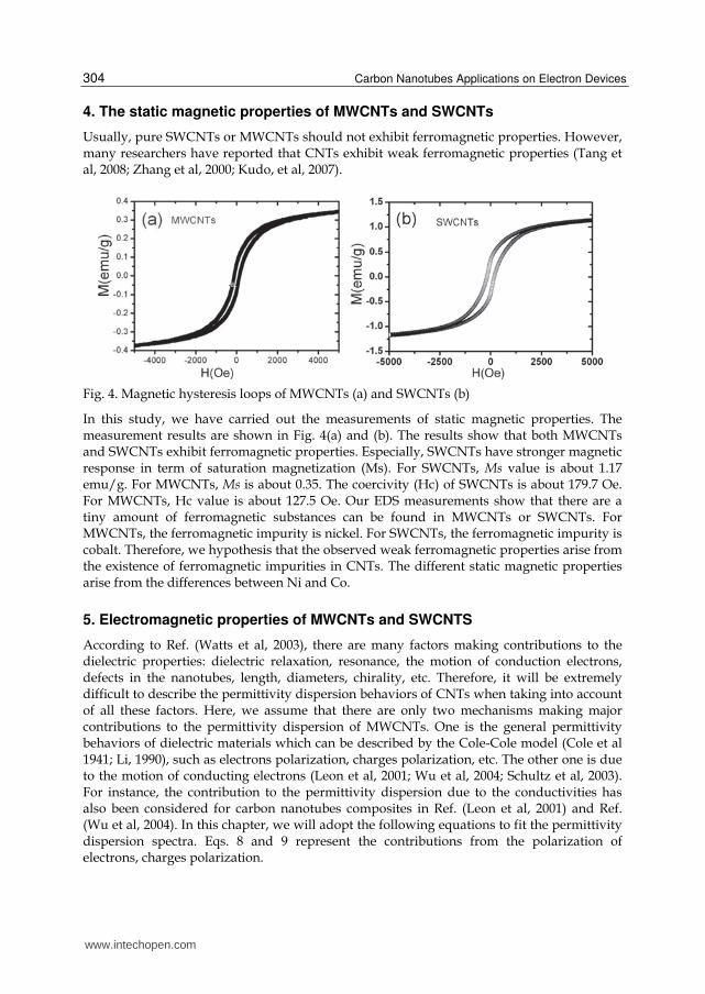
MWCNTs is about 1030 nm. The purities of MWCNTs and SWCNTs have been checked by the energy dispersive x-ray (EDX) measurements. The content of Ni impurity in MWCNTs is about 0.5 wt. %. The Co impurity in SWCNTs is about 0.2 wt. %. The images of MWCNTs were taken by a transmission electronic microscope (TEM). Field emission scanning electron microscopy (FE-SEM) images also have been taken for both SWCNTs and MWCNTs. In order to study the high frequency properties of MWCNTs and SWCNTs, toroidal samples with the inner, outer diameter and thickness as 3, 7 and 3.7 mm respectively were prepared by mixing the MWCNTs (SWCNTs) and wax for microwave measurements. The weight ratio of CNTs over wax is 0.2. The dependences of permittivity on frequency were theoretically studied based on the Cole-Cole law. With the obtained permeability and permittivity values, their electromagnetic wave absorption properties were evaluated and compared. To show the effect of CNTs on tuning the electromagnetic properties of ferrites,
we have synthesized spinel ferrites (Ni0.4Co0.24Zn0.36)Fe2O4 with average particle size of 23
www.intechopen.com
High Frequency Properties of Carbon Nanotubes and their Electromagnetic Wave Absorption Properties
301
m by sintering the oxide mixtures of Fe2O3, NiO, ZnO, and Co2O3 at 1250 °C for 2 h. The crystal structure of prepared ferrite checked by x-ray diffraction shows a typical spinel structure. We have prepared three samples to study the doping effect of MWCNTs on the electromagnetic properties of ferrites. Sample 0 has not been doped with MWCNTs. Sample 1 contains 5.2 wt. % MWCNTs. Sample 2 contains 10.4 wt. % MWCNTs. For these three ferrite samples, the weight percentage of wax is about 16%. The ferrite, MWCNT and wax are carefully mixed to ensure that the samples are homogenous and isotropic. The high frequency properties were also measured. All the high frequency measurements were carried out on an Agilent Vector Network Analyzer 8720 based on the transmission/reflection method. During a high frequency measurement, a sample under study was inserted into a segment of coaxial transmission line. All four scattering parameters can be obtained from the measurements.
2
211 1 2 2
(1 )
1S R
T
(1)
2
222 2 2 2
(1 )
1S R
T
(2)
2
21 12 1 2 2 2
(1 )
1S S R R
T
(3)
, where R1 and R2 are the reference plane transformations at two ports: Ri = exp(-Li) (i = 1, 2),
T is the transmission coefficient: T = exp(-L), where L is the thickness of sample under study.
The reflection coefficient can be given as:
/ 1
/ 1
r r
r r
(4)
Employing the Nicolson-Ross-Weir(NRW) algorithm, the complex relative permittivity and permeability can be derived from above equations, which are given as following:
2 20
1
(1 ) (1 / ) (1 / )r
c
(5)
20
2 2[(1 / ) (1 / )]r
r c
(6)
, where 0 is the free-space wavelength, c is the cutoff wavelength of the transmission line
section. For a coaxial line, c = .
22
1 1 1[ ln( )]2 D T (7)
More detailed descriptions on this measurement principle can be found in Ref. (Chen et al, 2004).
www.intechopen.com
Carbon Nanotubes Applications on Electron Devices
302
3. Morphologies of MWCNTs and SWCNTs
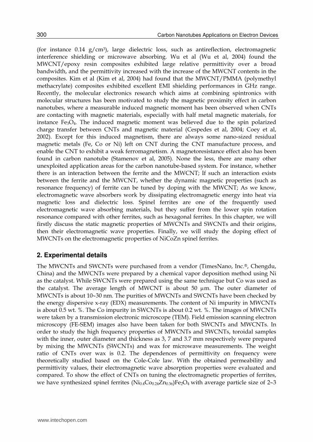
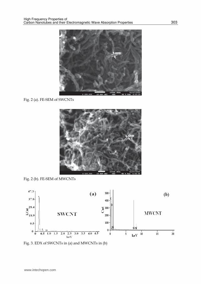
TEM images have been taken for both MWCNTs and SWCNTs, as shown in Fig. 1. Tabular structures can be seen in these images. FE-SEM images have also been taken for MWCNTs and SWCNTs, which are shown as Fig. 2(a) and (b). The diameter of SWCNTs is found to be around 18.4 nm. The diameter of MWCNTs is about 23.9 nm.
Fig. 1. TEM images of SWCNTs (a) and MWCNTs (b)
www.intechopen.com
High Frequency Properties of Carbon Nanotubes and their Electromagnetic Wave Absorption Properties
303
Fig. 2 (a). FE-SEM of SWCNTs
Fig. 2 (b). FE-SEM of MWCNTs
Fig. 3. EDX of SWCNTs in (a) and MWCNTs in (b)
www.intechopen.com
Carbon Nanotubes Applications on Electron Devices
304
4. The static magnetic properties of MWCNTs and SWCNTs
Usually, pure SWCNTs or MWCNTs should not exhibit ferromagnetic properties. However, many researchers have reported that CNTs exhibit weak ferromagnetic properties (Tang et al, 2008; Zhang et al, 2000; Kudo, et al, 2007).
Fig. 4. Magnetic hysteresis loops of MWCNTs (a) and SWCNTs (b)
In this study, we have carried out the measurements of static magnetic properties. The measurement results are shown in Fig. 4(a) and (b). The results show that both MWCNTs and SWCNTs exhibit ferromagnetic properties. Especially, SWCNTs have stronger magnetic response in term of saturation magnetization (Ms). For SWCNTs, Ms value is about 1.17 emu/g. For MWCNTs, Ms is about 0.35. The coercivity (Hc) of SWCNTs is about 179.7 Oe. For MWCNTs, Hc value is about 127.5 Oe. Our EDS measurements show that there are a tiny amount of ferromagnetic substances can be found in MWCNTs or SWCNTs. For MWCNTs, the ferromagnetic impurity is nickel. For SWCNTs, the ferromagnetic impurity is cobalt. Therefore, we hypothesis that the observed weak ferromagnetic properties arise from the existence of ferromagnetic impurities in CNTs. The different static magnetic properties arise from the differences between Ni and Co.
5. Electromagnetic properties of MWCNTs and SWCNTS
According to Ref. (Watts et al, 2003), there are many factors making contributions to the dielectric properties: dielectric relaxation, resonance, the motion of conduction electrons, defects in the nanotubes, length, diameters, chirality, etc. Therefore, it will be extremely difficult to describe the permittivity dispersion behaviors of CNTs when taking into account of all these factors. Here, we assume that there are only two mechanisms making major contributions to the permittivity dispersion of MWCNTs. One is the general permittivity behaviors of dielectric materials which can be described by the Cole-Cole model (Cole et al 1941; Li, 1990), such as electrons polarization, charges polarization, etc. The other one is due to the motion of conducting electrons (Leon et al, 2001; Wu et al, 2004; Schultz et al, 2003). For instance, the contribution to the permittivity dispersion due to the conductivities has also been considered for carbon nanotubes composites in Ref. (Leon et al, 2001) and Ref. (Wu et al, 2004). In this chapter, we will adopt the following equations to fit the permittivity dispersion spectra. Eqs. 8 and 9 represent the contributions from the polarization of electrons, charges polarization.
www.intechopen.com
High Frequency Properties of Carbon Nanotubes and their Electromagnetic Wave Absorption Properties
305
1
'2(1 )1
1 ( ) sin( / 2)( )
1 2( ) sin( / 2) ( )r rs r
(8)
1
"2(1 )1
( ) cos( / 2)( )
1 2( ) sin( / 2) ( )rs r
(9)
where 0 is the permittivity in free space, is the angular frequency, r is the permittivity
when frequency is infinity, rs is the static permittivity, is the relaxation time, is the
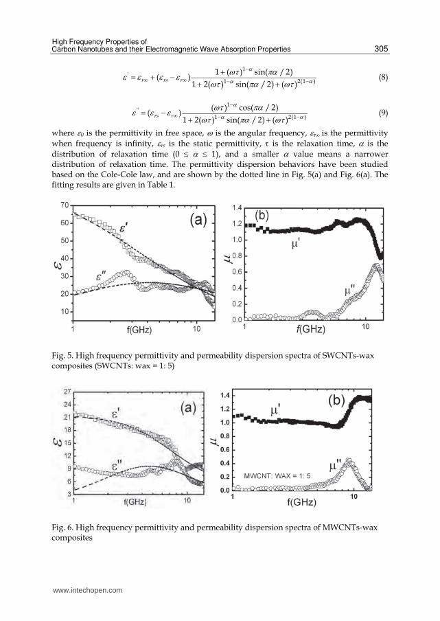
distribution of relaxation time (0 1), and a smaller value means a narrower distribution of relaxation time. The permittivity dispersion behaviors have been studied based on the Cole-Cole law, and are shown by the dotted line in Fig. 5(a) and Fig. 6(a). The fitting results are given in Table 1.
Fig. 5. High frequency permittivity and permeability dispersion spectra of SWCNTs-wax composites (SWCNTs: wax = 1: 5)
Fig. 6. High frequency permittivity and permeability dispersion spectra of MWCNTs-wax composites
www.intechopen.com
Carbon Nanotubes Applications on Electron Devices
306
Samples rs r
SWCNTs 4.5710-11 0.31 86.56 1.2810-11
MWCNTs 2.2010-11 3.2410-15 21.52 4.92
Table 1. Fitting results of permittivity spectra of MWCNTs and SWCNTs
As indicated in Table 1, in comparison to SWCNTs, MWCNTs have a smaller static
permittivity value and smaller value which means MWCNTs have a narrower distribution of polarization relaxation time. The dependences of permeability on frequency have been shown in Fig. 5(b) and Fig. 6(b) for SWCNTs and MWCNTs respectively. A major dispersion peak has been seen in each graph, which might be due to the existence of ferromagnetic impurity. For SWCNTs, the major resonance peak is around 12.4 GHz, while the major resonance peak of MWCNTs is found to be about 8.9 GHz. As we mentioned, SWCNTs contain a small quantity of Co. MWCNTs contain a small quantity of Ni, see Fig. 3(a) and
(b). According to the Snoek’ law (Snoek J. 1948): (s-1)fr = (2/3)4M0, where fr is proportional to the magnetocrystalline field. Therefore, the observed differences in permeability dispersion behaviors arise from their difference static properties. Such as the magnetocrystalline anisotropy of Co is larger than that of Ni, which will result in SWCNTs will have a larger resonance frequency than MWCNTs. With the obtained values of permittivity and permeability of the material under study, usually we can then evaluate the performance of electromagnetic absorber made from this material. The electromagnetic wave absorbing property of an absorber are dependent on six parameters, such as the
thickness (t) of the absorber, , , , and frequency (f). The criterion of absorption performance usually is expressed by the reflection loss (RL) in dB unit. Based on the measured complex permittivity and permeability, and we assume that a single layer of carbon nanotubes/paraffin composite is attached on a metal plate, then the electromagnetic wave absorbing properties usually can be evaluated by the following equation(Naito et al, 1971; Maeda et al, 2004):
0 020log ( ) /( )in inRL Z Z Z Z (10)
, where Z0 is the impedance of free space, Zin is the input impedance of the absorber, which can be expressed as:
0 / tanh{ (2 / ) }in r r r rZ Z j ft c (11)
, where c is the speed of light. Fig. 7 is a 3-dimensions graph which clearly shows the electromagnetic wave absorption properties of carbon nanotube/paraffin composite with different thickness within the measurement frequency range of 1-14 GHz. The color bar in Fig. 7 indicates different RL values in dB unit corresponding to different colors. Fig. 7(a) and (b) have shown the electromagnetic wave absorption properties of CNTs absorbers with different thickness (1-10 mm) within 1 – 14 GHz. It is clearly shown that MWCNTs have better electromagnetic wave absorption properties in terms of RL value. The minimum RL value of MWCNTs is about -20 dB. However, the minimum value of RL is -9.5 dB for SWCNTs. For many applications, the RL value smaller than -10 dB is accepted. A two-dimension contour map can be used to clearly show the electromagnetic wave absorption properties of absorbers with different thickness, which are given in Fig. 8(a). Learned from this map, the RL value of MWCNTs is less than -10 dB except for the
www.intechopen.com
High Frequency Properties of Carbon Nanotubes and their Electromagnetic Wave Absorption Properties
307
frequency range of 6-10 GHz and with the thickness ranging from 2.2 mm -3 mm. Especially, a thin MWCNTs absorber with a thickness of 1.62 mm can have an excellent absorption property (RL = -20 dB). Several examples showing the reflection loss of MWCNTs have been given for thickness of 1.62 mm, 2 mm, 4 mm and 6 mm, please see Fig. 8(b). The bandwidth with the RL value less than -10dB is respectively 0.56 GHz, 0.73 GHz, 1.90 GHz and 2.85 GHz for the thickness (t) as 6 mm, 4 mm, 2 mm and 1.62 mm. Compared with Fig. 8(b), Fig. 8(a) can give a straightforward presentation on the bandwidth of an absorber with different thickness.
Fig. 7. (a) Reflection loss of SWCNTs (1:5 wax) ; (b) MWCNTs (1:5 wax)
Fig. 8. (a) Contour map indicating the RL values less than -10 dB; (b) the RL~ f spectra of an absorber with different thickness values.
www.intechopen.com
Carbon Nanotubes Applications on Electron Devices
308
6. Doping effects of CNTs on electromagnetic properties of ferrites
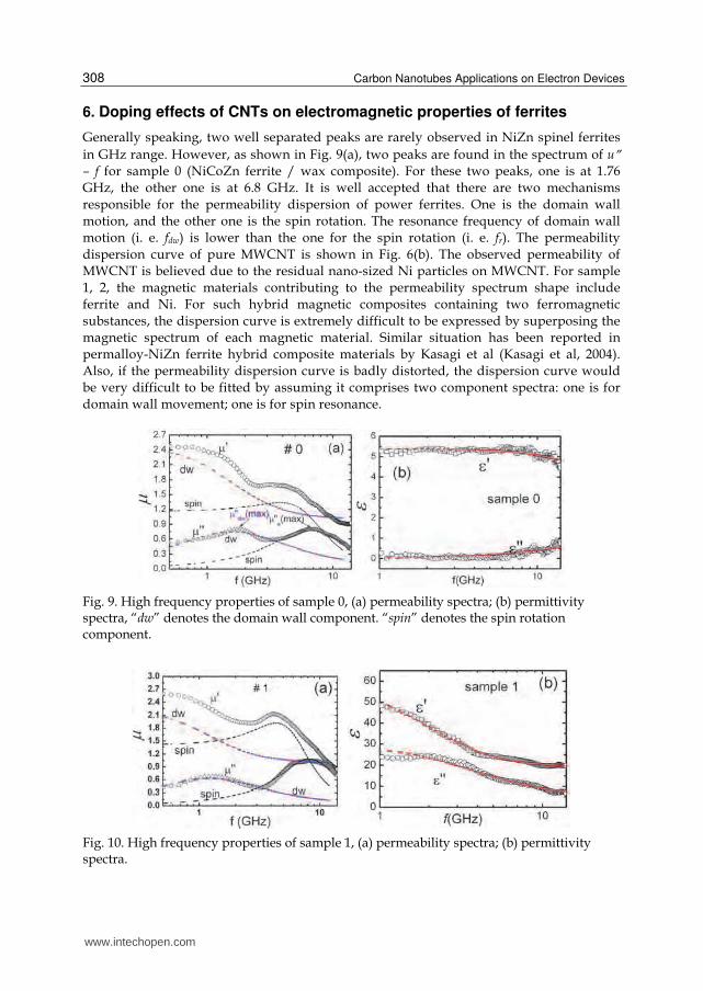
Generally speaking, two well separated peaks are rarely observed in NiZn spinel ferrites
in GHz range. However, as shown in Fig. 9(a), two peaks are found in the spectrum of u – f for sample 0 (NiCoZn ferrite / wax composite). For these two peaks, one is at 1.76 GHz, the other one is at 6.8 GHz. It is well accepted that there are two mechanisms
responsible for the permeability dispersion of power ferrites. One is the domain wall motion, and the other one is the spin rotation. The resonance frequency of domain wall motion (i. e. fdw) is lower than the one for the spin rotation (i. e. fr). The permeability
dispersion curve of pure MWCNT is shown in Fig. 6(b). The observed permeability of MWCNT is believed due to the residual nano-sized Ni particles on MWCNT. For sample 1, 2, the magnetic materials contributing to the permeability spectrum shape include ferrite and Ni. For such hybrid magnetic composites containing two ferromagnetic
substances, the dispersion curve is extremely difficult to be expressed by superposing the magnetic spectrum of each magnetic material. Similar situation has been reported in permalloy-NiZn ferrite hybrid composite materials by Kasagi et al (Kasagi et al, 2004).
Also, if the permeability dispersion curve is badly distorted, the dispersion curve would be very difficult to be fitted by assuming it comprises two component spectra: one is for domain wall movement; one is for spin resonance.
Fig. 9. High frequency properties of sample 0, (a) permeability spectra; (b) permittivity spectra, “dw” denotes the domain wall component. “spin” denotes the spin rotation component.
Fig. 10. High frequency properties of sample 1, (a) permeability spectra; (b) permittivity spectra.
www.intechopen.com
High Frequency Properties of Carbon Nanotubes and their Electromagnetic Wave Absorption Properties
309
Fig. 11. High frequency properties of sample 2, (a) permeability spectra (b) permittivity spectra
Based on the spectrum shape, we learn that the spectra in Fig. 9(a) are the relaxation type
because no negative values have been observed. Therefore, the resonances at lower frequencies in Fig. 9(a), 10(a) and 11(a) are due to the domain wall movement mechanism. The resonances at higher frequencies are due to the spin rotation mechanism. In Fig. 9(a), fdw and fs are 1.76 GHz, 6.80 GHz respectively for sample 0 without MWCNT. In Fig. 10 (a), fdw and fs are 1.28 GHz, 8.03 GHz for sample 1 with 5.2 wt% MWCNT. In Fig. 11 (a), fdw and fs are 1.98 GHz, 11.08 GHz for sample 2 with 10.4 wt% MWCNT. Clearly, the doping effect of MWCNT on the resonance frequency of spin rotation is much significant than that of domain wall movement. For the domain wall resonance with a relaxation type spectrum, the real part and imaginary part of permeability can be expressed by the Debye’s dispersion law (Liao, 1988):
'0 2
11
[1 ( / ) ]dw d
dwf f (12)
"0 2
/
[1 ( / ) ]dw
dw ddw
f f
f f (13)
, where d0 is the static susceptibility for domain wall movement. The resonance
frequency fdw above can be expressed by physical parameters as (Liao, 1988): fdw= (9 wall ) / (8 a 02 Ms2), where wall is the density of domain wall energy, a is the average
distance of impurities in a ferrite particle which impede the domain wall movements. is the electric resistivity of ferrite. Ms is the saturation magnetization. In our case, the
ferrites in different composite samples are same. Hence, wall can be considered as a
constant. The particle size of ferrites is about 23 m. Multi domains can exist in each ferrite particle, so the parameter a can be assumed as a constant. Then, as shown in this
equation, fdw is dependent on and Ms. It is well known that MWCNT is a substance
with very low resistivity and weak ferromagnetism. Doped with MWCNT, both and Ms of ferrite-wax composite will drop. Qualitively speaking, for sample 1, we can
conjure that the drop in is stronger than the drop in Ms, hence fdw is lower than the one for sample 0.
As for the spin resonance frequency fs, it depends on (Rado,1953): fs = (/2) HA, where is the gyromagnetic ratio, HA is the effective magnetic anisotropic field. In our case, the
www.intechopen.com
Carbon Nanotubes Applications on Electron Devices
310
permeability spectrum due to the spin rotation mechanism is a relaxation type. Accordingly it can be expressed as (Tsutaoka 2003):
2 2 2 2 2
' 02 2 2 2 2 2 2
[( ) ]1
[ (1 )] 4s s s
ss s
(14)
2 2 2
" 02 2 2 2 2 2 2
[ (1 )]
[ (1 )] 4s s s
ss s
(15)
, where s0 is the static susceptibility for spin rotation; s is the angular resonance
frequency; is the damping factor for spin rotation. is the angular frequency of
alternating magnetic field.
Fitting the experimental curves in Fig. 9(a), 10(a) and 11(a) with combined equations for -f (equations (12) + (14)) and -f (equations (13) + (15)) respectively is found extremely
difficult. Therefore, we have separately fitted the peaks for spin rotation component
(designated as “spin”) and domain wall component (designated as “dw”) in the spectra:
Firstly, we fit each peaks in the -f curves. Secondly, we calculate the -f curves by using
the obtained fitting parameters and corresponding expressions (equation 12 or 14). The
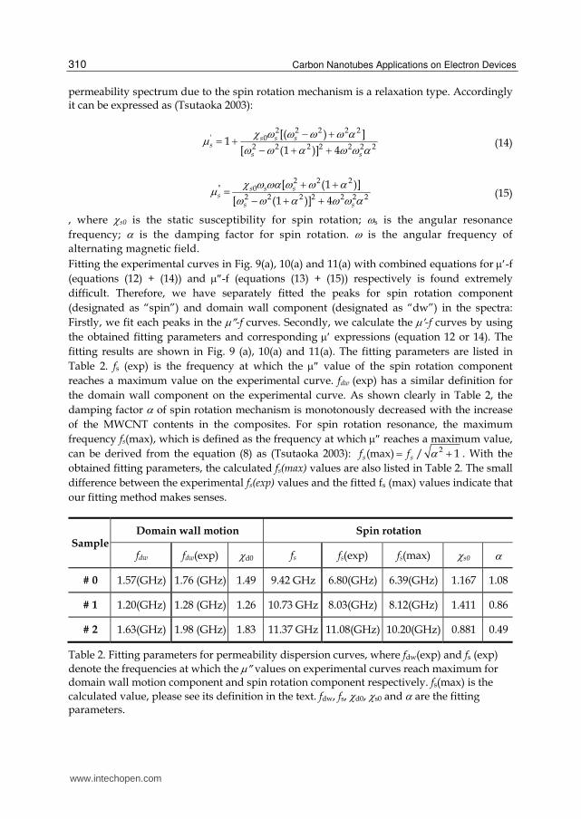
fitting results are shown in Fig. 9 (a), 10(a) and 11(a). The fitting parameters are listed in
Table 2. fs (exp) is the frequency at which the value of the spin rotation component
reaches a maximum value on the experimental curve. fdw (exp) has a similar definition for
the domain wall component on the experimental curve. As shown clearly in Table 2, the
damping factor of spin rotation mechanism is monotonously decreased with the increase
of the MWCNT contents in the composites. For spin rotation resonance, the maximum
frequency fs(max), which is defined as the frequency at which reaches a maximum value,
can be derived from the equation (8) as (Tsutaoka 2003): 2(max) / 1s sf f . With the
obtained fitting parameters, the calculated fs(max) values are also listed in Table 2. The small
difference between the experimental fs(exp) values and the fitted fs (max) values indicate that
Table 2. Fitting parameters for permeability dispersion curves, where fdw(exp) and fs (exp)
denote the frequencies at which the values on experimental curves reach maximum for domain wall motion component and spin rotation component respectively. fs(max) is the
calculated value, please see its definition in the text. fdw, fs, d0, s0 and are the fitting parameters.
www.intechopen.com
High Frequency Properties of Carbon Nanotubes and their Electromagnetic Wave Absorption Properties
311
Tsutaoka reported that in ferrite/resin composites, both fdw and fs increased with the decrease of the volume fraction of Ni-Zn ferrites (Tsutaoka 2003). They ascribed this to the
gap parameter (/D) in ferrite composites. According to their theory, a sphere ferrite particle (or a particle cluster) with a diameter of D is supposed to be enclosed by a layer of
nonmagnetic substance, such as epoxy resin. The thickness of nonmagnetic layer is /2. fdw
and fr can be expressed respectively as: 1/2(1 )dw B dw B dwf fD
and (1 )s B s B sf fD
,
where B-dw (fB-dw) and B-s (fB-s) are the static susceptibility (resonance frequency) of bulk ferrite for domain wall motion and spin rotation mechanisms respectively. As the concentration of nonmagnetic material increases (i.e., the concentration of magnetic material
decreases), the /D value increases. According to Tsutaoka’s theory (Tsutaoka 2003), it is clear that both fdw and fs increase with the decrease of ferrite content. However, in our case, the fdw value is not monotonously increased with the decrease of the ferrite content (83 wt%, 78 wt%, and 72.9 wt% for sample 0, 1, 2 respectively). For instance, fdw in sample 1 is lower than those in sample 0 and 2, see Table 2. Furthermore, we also found that with more MWCNT (15.6 wt %) added in the composite studied, the dispersion curve will be seriously distorted. In addition, the permeability behaviors of the MWCNT/NiCoZn ferrites/wax hybrid composites are different from the one reported by Tsutaoka (Tsutaoka 2003). Such an unusual behavior is believed due to the interactions between the MWCNTs and the NiCoZn ferrite particles. Interactions maybe occur between the residual nano-sized Ni particles in MWCNT and NiCoZn ferrites particles, or between the MWCNT and NiCoZn particles. Further investigation will be conducted in the future. The variation of permeability peak shapes also indirectly manifests the existence of such an interaction. The permittivity spectra for NiCoZn/MWCNT/wax hybrid composites are shown in Fig. 9(b),
10(b) and 11(b). For sample without MWCNT (sample 0), the values are almost constant
within the measurement frequency range: is about 5 and is about 0, showing a typical
feature of ferrite in GHz range. With increasing the MWCNT contents in composites (sample 1
and 2), both and increase within the frequency range, and both are gradually decreased
with increasing frequency. Especially, for sample 2, there is a clear inverse proportion
relationship between and frequency. This is a typical feature of a conducting media and
shows that with more MWCNT added into the studied composite, it will become a conducting
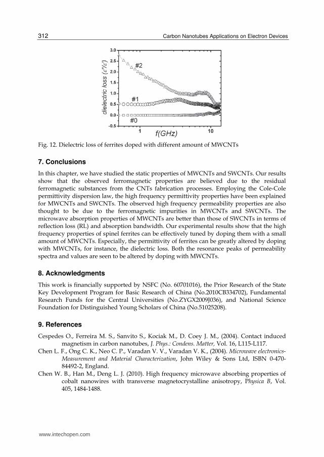
composite due to the high conductivity of MWCNT. At lower frequency range of 0.5 GHz - 6
GHz, sample 2 shows a significant dielectric loss, please see the / values in Fig. 12.
Samples (s) rs r
#0 3.8910-12 1.3910-14 5.38 1.1810-13
#1 7.9410-11 1.0810-16 57.38 18.89
#2 6.7010-10 0.57 249.00 2.05
Table 3. Fitting results of permittivity spectra of sample 0, 1 and 2.
The permittivity dispersion spectra of these three samples have been studied based on the previous Cole-Cole dispersion law. The fitting spectra shown as the dotted lines are also presented in the above figures. The fitting results are given in Table 3. It is clear that both
the static permittivity value (rs) and the relaxation time () increase with more MWCNTs added into the ferrites.
www.intechopen.com
Carbon Nanotubes Applications on Electron Devices
312
Fig. 12. Dielectric loss of ferrites doped with different amount of MWCNTs
7. Conclusions
In this chapter, we have studied the static properties of MWCNTs and SWCNTs. Our results show that the observed ferromagnetic properties are believed due to the residual ferromagnetic substances from the CNTs fabrication processes. Employing the Cole-Cole permittivity dispersion law, the high frequency permittivity properties have been explained for MWCNTs and SWCNTs. The observed high frequency permeability properties are also thought to be due to the ferromagnetic impurities in MWCNTs and SWCNTs. The microwave absorption properties of MWCNTs are better than those of SWCNTs in terms of reflection loss (RL) and absorption bandwidth. Our experimental results show that the high frequency properties of spinel ferrites can be effectively tuned by doping them with a small amount of MWCNTs. Especially, the permittivity of ferrites can be greatly altered by doping with MWCNTs, for instance, the dielectric loss. Both the resonance peaks of permeability spectra and values are seen to be altered by doping with MWCNTs.
8. Acknowledgments
This work is financially supported by NSFC (No. 60701016), the Prior Research of the State Key Development Program for Basic Research of China (No.2010CB334702), Fundamental Research Funds for the Central Universities (No.ZYGX2009J036), and National Science Foundation for Distinguished Young Scholars of China (No.51025208).
9. References
Cespedes O., Ferreira M. S., Sanvito S., Kociak M., D. Coey J. M., (2004). Contact induced magnetism in carbon nanotubes, J. Phys.: Condens. Matter, Vol. 16, L115-L117.
Chen L. F., Ong C. K., Neo C. P., Varadan V. V., Varadan V. K., (2004). Microwave electronics-Measurement and Material Characterization, John Wiley & Sons Ltd, ISBN 0-470-84492-2, England.
Chen W. B., Han M., Deng L. J. (2010). High frequency microwave absorbing properties of cobalt nanowires with transverse magnetocrystalline anisotropy, Physica B, Vol. 405, 1484-1488.
www.intechopen.com
High Frequency Properties of Carbon Nanotubes and their Electromagnetic Wave Absorption Properties
313
Cole K. S., Cole R. H., (1941). Dispersion and Absorption in Dielectrics, J. Chem. Phys. Vol. 9, 341-343.
Coey J. M. D., Venkatesan M., Fitzgerald C. B., Douvalis A. P., Sanders I. S. (2002). Ferromagnetism of a graphite nodule from the Canyon Diablo meteorite, Nature, Vol. 420, 156-158.
Han M., Lu H. P., and Deng L. J. (2010). Control of gigahertz permeability and permittivity dispersion by means of nanocrystallization in FeCo based nanocrystalline alloy, Appl. Phys. Lett. Vol. 97, 1925071-1925073.
Han M., Tang W., Chen W.B., Zhou H., Deng L. J. (2010). Effect of shape of Fe particles on their electromagnetic properties within 1–18 GHz range, J. Appl. Phys, Vol. 107, 09A9581-09A9583.
Han M., Ou Y., Deng L. J. (2009). Microwave absorption properties of double-layer absorbers made of NiCoZn ferrites and hollow glass microspheres electroless plated with FeCoNiB , J. Magn. Magn. Mater. Vol. 321, 1125-1129.
Han M., Ou Y., Liang D. F., and Deng L. J. (2009). Annealing effects on the microwave permittivity and permeability properties of Fe79Si16B5 microwires and their microwave absorption performances, Chin. Phys. B, Vol. 18, No 3, 1261-1265.
Iijima S. (1991). Helical microtubules of graphitic carbon, Nature, Vol. 354, 56-58. Kasagi T., Tsutaoka T., Hatakeyama K. (2004). Complex permeability of permalloy-ferrite
hybrid composite materials, J. Magn. Magn. Mater. Vol. 272-276, 2224-2226. Kim H. M., Kim K., Lee C. Y., Joo J., Cho S. J., Pejakovic D. A., Yoo J. W., Epstein A. J. (2004).
Electrical conductivity and electromagnetic interference shielding of multiwalled carbon nanotube composites containing Fe catalyst, Appl Phys. Lett. Vol. 84, 589-591.
Kudo Y., Hira T., Ishii S., Morisato T., Ohno K. (2007). Interaction between Fe and single-walled carbon nanotube near the entrance, J. Phys.: Conf. Ser. Vol. 61, 633-637.
Leon C., Rivera A., Varez A., Sanz J., and Santamaria J., (2001). Origin of constant loss in ionic conductors, Phys. Rev. Lett. Vol. 86, 1279-1281.
Liao S. B. (1988). Ferromagnetism (in Chinese), Sciences Publishing House, Beijing.
Li H. R. (1990). Introduction to Physics of Dielectrics, 1st ed. University of Science and Technology of Chengdu, Chengdu.
Lu R. T., Shi J. J., Baca F. J., Wu J. Z. (2010). High performance multiwall carbon nanotube bolometers, J. Appl. Phys. Vol. 108, 084305-084309.
Maeda T., Sugimoto S., Kagotani T., Tezuka N., and Inomata K. (2004). Effect of the soft/hard exchange interaction on natural resonance frequency and electromagnetic wave absorption of the rare earth-iron-boron compounds, J. Magn. Magn. Mater. Vol. 281, No. 2-3, 195-205.
Mintmire J. W., Dunlap B. I., White C. T. (1992). Are fullerene tubules metallic? Phys. Rev. Lett. Vol. 68, 631-634.
Naito Y. and Suetake K. (1971). Application of ferrite to electromagnetic wave absorber and its characteristics, IEEE Trans. Microw. Theory Techn. Vol. 19, No. 1, 65-72.
Nakata T., Watanabe M. (2011). Nanometer-resolution optical probe using a metallic-nanoparticle-intercalated carbon nanotube, J. Appl. Phys. Vol.109, 013110-013114.
Poncharal P., Wang Z. L., Ugarte D., de Heer W. A. (1999). Electrostatic deflections and electromechanical resonances of carbon nanotubes, Science, Vol. 283, No. 5407, 1513-1516.
Rado G. (1953). Magnetic spectra of ferrites, Rev. Mod. Phys. Vol. 25, 81-89.
www.intechopen.com
Carbon Nanotubes Applications on Electron Devices
314
Schultz J. W. and Moore R. L. (2003). Effective Medium Calculations of the Electromagnetic Behavior of Single Walled Carbon Nanotube Composites, Mater. Res. Soc. Symp. Proc. Vol. 739,151-153.
Snoek J. L. (1948). Dispersion and Absorption in Magnetic Ferrites at Frequencies above One Megacycle, Physica, Vol. 14, No. 4, 207-217.
Stamenov P., Coey J. M. D. (2005). Magnetic susceptibility of carbon--experiment and theory, J. Magn. Magn. Mater. Vol. 290-291, No. 1, 279-285.
Tang N. J., Zhong W., Au C. K., Yang Y., Han M., Lin K, J., Du Y. W. (2008). Synthesis, Microwave Electromagnetic, and Microwave Absorption Properties of Twin Carbon Nanocoils, J. Phys. Chem. C, Vol. 112, No. 49, 19316-19323.
Tooski S. B. (2011). Theoretical study of carbon-nanotube-based gas pressure sensors, J. Appl. Phys. Vol. 109, 014318-014324.
Tsutaoka T. (2003). Frequency dispersion of complex permeability in Mn–Zn and Ni–Zn spinel ferrites and their composite materials, J. Appl. Phys., Vol. 93, 2789-2796.
Watts P. C. P., Hsu W. K., Barnes A., and Chambers B. (2003). High Permittivity from Defective Multiwalled Carbon Nanotubes in the X‐Band, Adv. Mater. Vol. 15, No. 7-
8, 600-603.
Matitsine S. M., Liu L., Chen L. F., Gan Y. B., and Ong C. K. (2005). Comment on "High microwave permittivity of multiwalled carbon nanotube composites", Appl. Phys. Lett. Vol. 87, 0161011-0161013.
Wu J. H., Kong L. B. (2004). High microwave permittivity of multiwalled carbon nanotube composites, Appl. Phys. Lett. Vol. 84, 49561-49563.
Wang L., Dang Z. M. (2005). Carbon nanotube composites with high dielectric constant at low percolation threshold, Appl. Phys. Lett. Vol. 87, 0429031-0429033.
Xie J. L., Han M., Chen L., Kuang R. X. , Deng L. J. (2007). Microwave-absorbing properties of NiCoZn spinel ferrites, J. Magn. Magn. Mater. Vol. 314, 37-42.
Xu Y., Zhang Y., Suhir E. (2006). Thermal properties of carbon nanotube array used for integrated circuit cooling, J. Appl. Phys. Vol. 100, 074302-074306.
Zhang Y., Franklin N. W., Chen R. J., and Dai H. (2000). Metal coating on suspended carbon nanotubes and its implication to metal-tube interaction, Chem. Phys. Lett. Vol. 331, No. 1, 35-41.
Zhao G. L., Bagayoko D., Yang L.(2006). Optical properties of aligned carbon nanotube mats for photonic applications, J. Appl. Phys. 99, 114311-114315.
www.intechopen.com
Carbon Nanotubes Applications on Electron DevicesEdited by Prof. Jose Mauricio Marulanda
ISBN 978-953-307-496-2Hard cover, 556 pagesPublisher InTechPublished online 01, August, 2011Published in print edition August, 2011
InTech ChinaUnit 405, Office Block, Hotel Equatorial Shanghai No.65, Yan An Road (West), Shanghai, 200040, China
Phone: +86-21-62489820 Fax: +86-21-62489821
Carbon nanotubes (CNTs), discovered in 1991, have been a subject of intensive research for a wide range ofapplications. In the past decades, although carbon nanotubes have undergone massive research, consideringthe success of silicon, it has, nonetheless, been difficult to appreciate the potential influence of carbonnanotubes in current technology. The main objective of this book is therefore to give a wide variety of possibleapplications of carbon nanotubes in many industries related to electron device technology. This should allowthe user to better appreciate the potential of these innovating nanometer sized materials. Readers of this bookshould have a good background on electron devices and semiconductor device physics as this book presentsexcellent results on possible device applications of carbon nanotubes. This book begins with an analysis onfabrication techniques, followed by a study on current models, and it presents a significant amount of work ondifferent devices and applications available to current technology.
How to referenceIn order to correctly reference this scholarly work, feel free to copy and paste the following:
Mangui Han and Longjiang Deng (2011). High Frequency Properties of Carbon Nanotubes and TheirElectromagnetic Wave Absorption Properties, Carbon Nanotubes Applications on Electron Devices, Prof. JoseMauricio Marulanda (Ed.), ISBN: 978-953-307-496-2, InTech, Available from:http://www.intechopen.com/books/carbon-nanotubes-applications-on-electron-devices/high-frequency-properties-of-carbon-nanotubes-and-their-electromagnetic-wave-absorption-properties