High-fidelity finite element modeling and analysis of adaptive gas turbine stator–rotor flow interaction at off-design conditions Nikita Kozak a , Fei Xu a,b , Manoj R. Rajanna a , Luis Bravo c , Muthuvel Murugan c , Anindya Ghoshal c , Yuri Bazilevs d , Ming-Chen Hsu a,* a Department of Mechanical Engineering, Iowa State University, Ames, Iowa 50011, USA b Ansys Inc., 807 Las Cimas Parkway, Austin, Texas 78746, USA c U.S. Army Research Laboratory, Aberdeen Proving Ground, Maryland 21005, USA d School of Engineering, Brown University, Providence, Rhode Island 02912, USA Abstract The objective of this work is to computationally investigate the impact of an incidence-tolerant rotor blade concept on gas turbine engine performance under off-design conditions. When a gas turbine operates at an off-design condition such as hover flight or takeoff, large-scale flow separa- tion can occur around turbine blades, which causes performance degradation, excessive noise, and critical loss of operability. To alleviate this shortcoming, a novel concept which articulates the ro- tating turbine blades simultaneous with the stator vanes is explored. We use a finite-element-based moving-domain computational fluid dynamics (CFD) framework to model a single high-pressure turbine stage. The rotor speeds investigated range from 100% down to 50% of the designed condi- tion of 44,700 rpm. This study explores the limits of rotor blade articulation angles and determines the maximal performance benefits in terms of turbine output power and adiabatic efficiency. The results show articulating rotor blades can achieve an efficiency gain of 10% at off-design condi- tions thereby providing critical leap-ahead design capabilities for the U.S. Army Future Vertical Lift (FVL) program. Keywords: Compressible flow; Stabilized finite element methods; Gas turbine; Off-design performance Contents 1 Introduction 2 2 Computational modeling and analysis 3 2.1 Finite element modeling ............................... 3 * Corresponding author Email address: [email protected](Ming-Chen Hsu) Preprint submitted to Journal of Mechanics November 8, 2019
Transcript
High-fidelity finite element modeling and analysis of adaptive gasturbine stator–rotor flow interaction at off-design conditions
Nikita Kozaka, Fei Xua,b, Manoj R. Rajannaa, Luis Bravoc, Muthuvel Muruganc,Anindya Ghoshalc, Yuri Bazilevsd, Ming-Chen Hsua,∗
aDepartment of Mechanical Engineering, Iowa State University, Ames, Iowa 50011, USAbAnsys Inc., 807 Las Cimas Parkway, Austin, Texas 78746, USA
cU.S. Army Research Laboratory, Aberdeen Proving Ground, Maryland 21005, USAdSchool of Engineering, Brown University, Providence, Rhode Island 02912, USA
Abstract
The objective of this work is to computationally investigate the impact of an incidence-tolerantrotor blade concept on gas turbine engine performance under off-design conditions. When a gasturbine operates at an off-design condition such as hover flight or takeoff, large-scale flow separa-tion can occur around turbine blades, which causes performance degradation, excessive noise, andcritical loss of operability. To alleviate this shortcoming, a novel concept which articulates the ro-tating turbine blades simultaneous with the stator vanes is explored. We use a finite-element-basedmoving-domain computational fluid dynamics (CFD) framework to model a single high-pressureturbine stage. The rotor speeds investigated range from 100% down to 50% of the designed condi-tion of 44,700 rpm. This study explores the limits of rotor blade articulation angles and determinesthe maximal performance benefits in terms of turbine output power and adiabatic efficiency. Theresults show articulating rotor blades can achieve an efficiency gain of 10% at off-design condi-tions thereby providing critical leap-ahead design capabilities for the U.S. Army Future VerticalLift (FVL) program.
Keywords: Compressible flow; Stabilized finite element methods; Gas turbine; Off-designperformance
Although the development of a gas turbine engine is considered mature, the ever-higher powerand efficiency requirements needed to advance today’s propulsion systems call for innovation [1–3]. One promising development to address this call is the variable speed power turbine (VSPT),which would be able to meet the requested power and efficiency levels in a wider range of operat-ing conditions. A VSPT would be able to alter its operating speed without facing the substantialperformance losses that today’s engines experience at off-design conditions [1, 4]. An off-designcondition is an operating speed that the engine was not designed to operate at, typically any speedother than 100%. The cause of performance losses at off-design operation stems from the aero-dynamic flow separation around the turbine blades. The VSPT can be specifically applicable tothe U.S. Army Future Vertical Lift (FVL) effort, where it would be deployed to overcome thechallenges associated with off-design operations.
The idea of VSPT could be enabled by a novel incidence-tolerant rotor blade concept [5] knownas the adaptive turbomachinery blade [6]. Adaptive turbomachinery blades would maintain optimalflow patterns and therefore, achieve satisfactory performance in a wide range of operating condi-tions [2, 3]. These flow patterns will be maintained by synchronously articulating the turbine’sstator and rotor blades to limit the presence of flow separation. Figure 1(a) illustrates the exterioractuators which would enable stator articulation. This use of exterior actuators is common forarticulating the compressor inlet vanes [7–9]. However, rotor articulation utilizes a novel conceptof interior actuators. This mechanism, depicted in Figure 1(b), will be located within the turbine’sshaft and features multiple actuators to pitch the blades while maintaining a balanced disk.
The lack of understanding on the complex internal flows of a gas turbine stage, specifically onunsteady flow separation, acts as a barrier in continuing the development of adaptive turbomachin-
2
SMA torque-tube Articulation gear housing
Engine casingBlade attachment circular base
Torque-tube drive gear
Stator blade
Blade articulation gear
Air flow
(a) Stator articulation
Actuator-gear
Blade pitch pin attachment
Rotor blade
Blade base
Air flow
Turbine disk SMA torque-tube and attachment
Blade pitch gear
Turbine disk shaft
(b) Rotor articulation
Figure 1: Proposed stator and rotor articulation mechanisms in Murugan et al. [6].
ery blades. This barrier stems from the reason that generic flow separation leads to the formationof dynamic-stall-like vortices whose evolution and interaction with surfaces generate inconstantforces along the airfoil blades and have a significant impact on performance [2, 3, 10–12]. Theseperformance impacts include lowered power and efficiency as well as increased structure stress,noise and likelihood of stall and shocks [2, 3, 10].
Previous experimental and numerical investigations [13, 14] have focused on understandingthe aerodynamic phenomena related to blade articulation within the compressor section of the gasturbine engine. Due to the lack of mechanism for rotor blade articulation, these studies providedlimited information on rotor blade articulation. Therefore, to overcome this knowledge barrier andfurther the development of adaptive blade technology, this work utilizes a novel finite element-based moving-domain computational fluid dynamics (CFD) framework [15] to investigate the re-lationship of rotor blade articulation and turbine stage flow separation and performance.
This paper is organized as follows. In Section 2, we summarize the finite element methodsused in this work for the CFD analysis of a gas turbine. The turbine stage geometry, modelingsetup, and variables of interest are also described. In Section 3, we present and discuss the resultsof a mesh convergence study and an extensive investigation on the flow fields and gas turbine per-formance impacted by the rotor articulation under both design and off-design conditions. Finally,the conclusions of this study and the path forward are summarized in Section 4.
2. Computational modeling and analysis
2.1. Finite element modeling
The fluid flow inside gas turbines spans a wide range of flow regimes from subsonic to super-sonic. To accommodate such a wide range of Mach numbers, a suitable CFD simulation methodneeds to be robust across the entire regime. In this paper, we utilize the stabilized finite element for-mulation for the Navier–Stokes equations of compressible flows on moving domains in an arbitrary
3
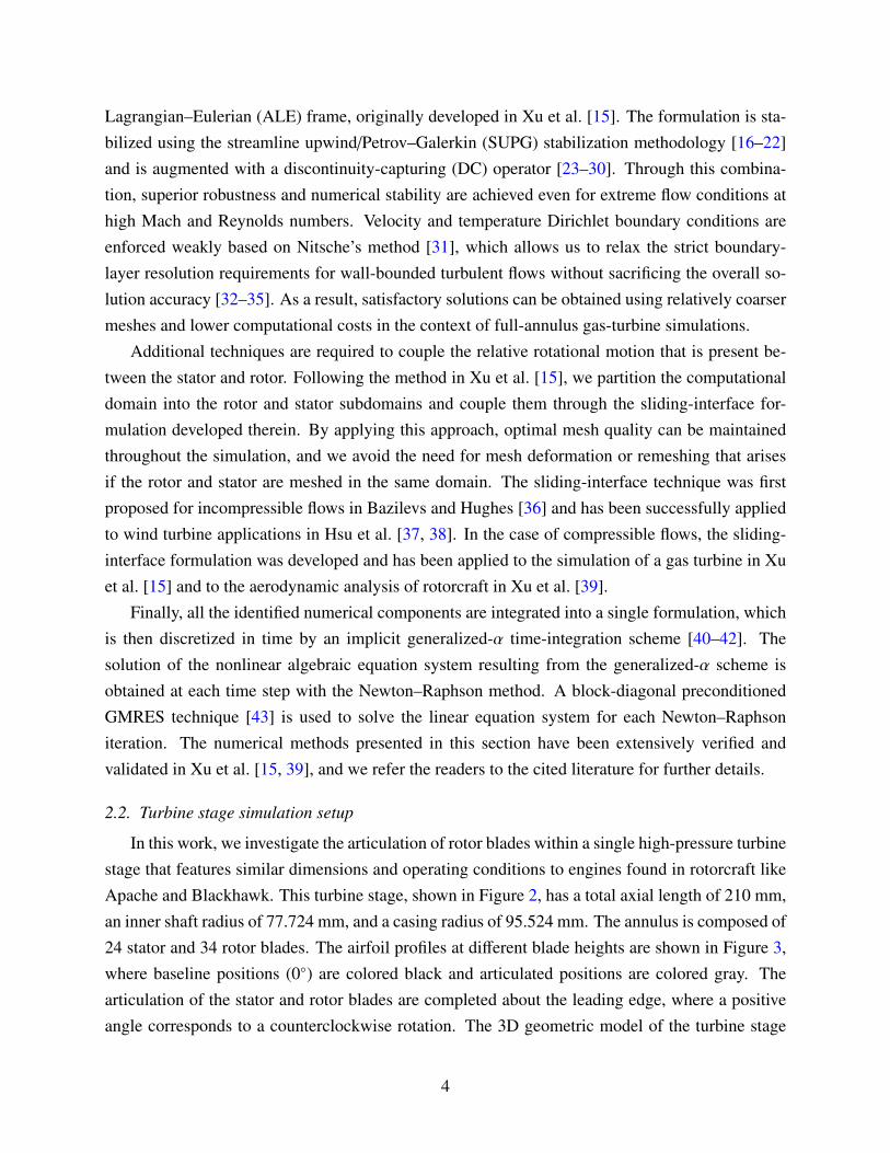
Lagrangian–Eulerian (ALE) frame, originally developed in Xu et al. [15]. The formulation is sta-bilized using the streamline upwind/Petrov–Galerkin (SUPG) stabilization methodology [16–22]and is augmented with a discontinuity-capturing (DC) operator [23–30]. Through this combina-tion, superior robustness and numerical stability are achieved even for extreme flow conditions athigh Mach and Reynolds numbers. Velocity and temperature Dirichlet boundary conditions areenforced weakly based on Nitsche’s method [31], which allows us to relax the strict boundary-layer resolution requirements for wall-bounded turbulent flows without sacrificing the overall so-lution accuracy [32–35]. As a result, satisfactory solutions can be obtained using relatively coarsermeshes and lower computational costs in the context of full-annulus gas-turbine simulations.
Additional techniques are required to couple the relative rotational motion that is present be-tween the stator and rotor. Following the method in Xu et al. [15], we partition the computationaldomain into the rotor and stator subdomains and couple them through the sliding-interface for-mulation developed therein. By applying this approach, optimal mesh quality can be maintainedthroughout the simulation, and we avoid the need for mesh deformation or remeshing that arisesif the rotor and stator are meshed in the same domain. The sliding-interface technique was firstproposed for incompressible flows in Bazilevs and Hughes [36] and has been successfully appliedto wind turbine applications in Hsu et al. [37, 38]. In the case of compressible flows, the sliding-interface formulation was developed and has been applied to the simulation of a gas turbine in Xuet al. [15] and to the aerodynamic analysis of rotorcraft in Xu et al. [39].
Finally, all the identified numerical components are integrated into a single formulation, whichis then discretized in time by an implicit generalized-α time-integration scheme [40–42]. Thesolution of the nonlinear algebraic equation system resulting from the generalized-α scheme isobtained at each time step with the Newton–Raphson method. A block-diagonal preconditionedGMRES technique [43] is used to solve the linear equation system for each Newton–Raphsoniteration. The numerical methods presented in this section have been extensively verified andvalidated in Xu et al. [15, 39], and we refer the readers to the cited literature for further details.
2.2. Turbine stage simulation setup
In this work, we investigate the articulation of rotor blades within a single high-pressure turbinestage that features similar dimensions and operating conditions to engines found in rotorcraft likeApache and Blackhawk. This turbine stage, shown in Figure 2, has a total axial length of 210 mm,an inner shaft radius of 77.724 mm, and a casing radius of 95.524 mm. The annulus is composed of24 stator and 34 rotor blades. The airfoil profiles at different blade heights are shown in Figure 3,where baseline positions (0◦) are colored black and articulated positions are colored gray. Thearticulation of the stator and rotor blades are completed about the leading edge, where a positiveangle corresponds to a counterclockwise rotation. The 3D geometric model of the turbine stage
Figure 2: Problem setup, geometry and dimensions of the turbine stage.
Figure 3: Illustration of stator and rotor airfoil profiles at different blade heights and their baseline (0◦) and articulatedpositions. Baseline positions are colored black and articulated positions are colored gray. A positive angle correspondsto a counterclockwise articulation.
is generated using a parametric design tool proposed in Xu et al. [15], based on the idea of aninteractive geometry modeling platform [44]. The design tool allows us to parametrically pitch theblade in the computer-aided design (CAD) model through input parameters that control the pitchangles of the rotor and stator blades. This approach enables us to efficiently carry out a series ofgas-turbine simulations at different blade angles.
We consider a turbine stage designed to operate at application specific conditions to meet FVLrequirements. We operate this stage at two off-design operating speeds of 22,350 rpm (50%) and33,525 rpm (75%) as well as a design speed of 44,700 rpm (100%). These operating speedseffectively replicate different engine conditions that are seen during cruise, hover, and takeoff,
5
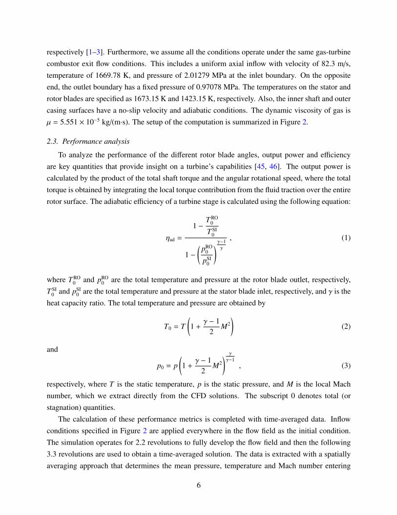
respectively [1–3]. Furthermore, we assume all the conditions operate under the same gas-turbinecombustor exit flow conditions. This includes a uniform axial inflow with velocity of 82.3 m/s,temperature of 1669.78 K, and pressure of 2.01279 MPa at the inlet boundary. On the oppositeend, the outlet boundary has a fixed pressure of 0.97078 MPa. The temperatures on the stator androtor blades are specified as 1673.15 K and 1423.15 K, respectively. Also, the inner shaft and outercasing surfaces have a no-slip velocity and adiabatic conditions. The dynamic viscosity of gas isµ = 5.551 × 10⁻⁵ kg/(m·s). The setup of the computation is summarized in Figure 2.
2.3. Performance analysis
To analyze the performance of the different rotor blade angles, output power and efficiencyare key quantities that provide insight on a turbine’s capabilities [45, 46]. The output power iscalculated by the product of the total shaft torque and the angular rotational speed, where the totaltorque is obtained by integrating the local torque contribution from the fluid traction over the entirerotor surface. The adiabatic efficiency of a turbine stage is calculated using the following equation:
ηad =
1 −T RO
0
T SI0
1 −(
pRO0
pSI0
)γ−1γ
, (1)
where T RO0 and pRO
0 are the total temperature and pressure at the rotor blade outlet, respectively,T SI
0 and pSI0 are the total temperature and pressure at the stator blade inlet, respectively, and γ is the
heat capacity ratio. The total temperature and pressure are obtained by
T0 = T(1 +
γ − 12
M2)
(2)
and
p0 = p(1 +
γ − 12
M2) γ
γ−1, (3)
respectively, where T is the static temperature, p is the static pressure, and M is the local Machnumber, which we extract directly from the CFD solutions. The subscript 0 denotes total (orstagnation) quantities.
The calculation of these performance metrics is completed with time-averaged data. Inflowconditions specified in Figure 2 are applied everywhere in the flow field as the initial condition.The simulation operates for 2.2 revolutions to fully develop the flow field and then the following3.3 revolutions are used to obtain a time-averaged solution. The data is extracted with a spatiallyaveraging approach that determines the mean pressure, temperature and Mach number entering
6
Table 1: Mesh convergence study: statistics of meshes and results.
and exiting the blade passage. These values are obtained by averaging annular slices on a 0.5mm interval that are between 3 mm and 7 mm upstream from the leading edge of the stator anddownstream from the trailing edge of the rotor. This approach reduces the uncertainty caused byextracting data from a single plane.
For the 3D simulation results presented in the following section, the time-averaged rotor bladepressure contours, vortical structures (Q-criterion [47] isosurfaces), and streamlines in the rotorblade passage are analyzed to locate and rate the magnitude of flow separation, and to identify andanalyze recirculation zones and pressure disparity regions.
3. Results and discussion
3.1. Mesh convergence study
We first carry out a mesh convergence study to determine the mesh resolution that yields ac-curate simulation results of the gas turbine flows in this work. Following the same mesh designstrategy in Xu et al. [15, Section 4.1], we construct four meshes of different refinement levels, withblade surface element sizes being 2.4 mm, 1.2 mm, 0.6 mm and 0.3 mm, listed in Table 1. Forreference, the rotor blade has a chord length of 20.8 mm. Mesh 3, which has a blade element sizeof 0.6 mm, employs the same mesh resolution as the one used in Xu et al. [15, Figure 19].
Simulations are carried out on all four meshes using the baseline blade design with the stageoperating at 100% speed. Table 1 shows the power output for all four cases, with Mesh 3 achievinga relative error of 0.39% with reference to the most refined case. Given the complexity of thesimulation problem, we conclude that a converged solution is achieved at this mesh resolution forthe purpose of the present study. For all other simulation cases with rotor blade articulations, thesame resolution as Mesh 3 is applied.
3.2. Effect of off-design rotor speeds
To understand the effect of off-design rotor speeds, we examine and compare the flows insidethe stage under 100% and 50% rotor speeds, simulated with the baseline blade design (0◦), shownin Figures 4 and 5, respectively. We focus on the flow separation, which can lead to performancedegradation and critical loss of operability. The flow separation is identify in the streamline plots
7
by examining the path of the lines [11]. A line that moves away from the suction side of the bladeis said to be detached and separated. The location where the line strays from the suction side isknown as the point of separation and the magnitude of flow separation can be derived by how faraway the lines move from both the suction and pressure sides. Another indication of increasedflow separation is the formation and growth of recirculation zones and slow traveling flow which isillustrated by the curl of the streamlines. Flow separation can also be seen in the Q-criterion plotsthat illustrate the vortical structures of the flow [47, 48]. A vortical structure that is larger in sizeand colored at a lower speed is the result of increased flow separation. These structures are bestobserved in the passage near the blade and when the flow exits the passage. Finally, we look at thepressure contour on the blade surfaces to identify adverse pressure gradient that causes the flowseparation.
Figures 4 and 5 show that the 0◦ case at 50% speed features higher velocity gradients near theleading edge of the suction side, the trailing edge on the pressure side, and in the downstream flow.These gradients amplify high and low velocity regions that imply an increase in flow separationand are shown in the streamline and relative velocity contour plots. Furthermore, this separationleads to increased vortex core regions in the areas of increased velocity gradients as shown in theQ-criterion plots. The pressure contours depict a gradient in the opposite direction of the mainstream flow at the 50% operating speed on the suction surface. This addresses the root cause ofincreased flow separation with operation at an off-design rotor speed. As will become evident inthe following sections, this flow separation can adversely influence the gas turbine performancemetrics.
3.3. Moderate rotor articulation
It was stated in Murugan et al. [6] that the proposed mechanism for blade articulation couldhave the capability to pitch the blades ±15◦ to address the shortcomings discussed in the previoussection. Motivated by this, we first primarily focus on exploring the influence of this mechanismwithin the moderate range of rotor blades.
The influence of rotor blade articulation in the positive angle is discussed by comparing twoblade angles at the same rotor speed. Referencing the cases with the rotor at 0◦ and 8◦, shown inFigures 4 and 5, we observe the increase of flow separation with a positive articulation. We seethis increase at both speeds with the point of separation occurring closer to the leading edge andthe reduction of flow speed in the passage at 8◦. These changes in the flow are reflected in theQ-criterion plots by the growth of vortical structures in the passage of the blade and downstream.The pressure contours supports this increase of flow separation by the increased adverse pressuregradients shown near the leading edge on the suction side of the blade. All of these trends stay truefor other positive articulations in the moderate range.
8
Streamline Plot Q-criterion Plot Front Pressure Contour Rear Pressure Contour
-15°
-8°
0°
8°
Inner hub
Inner hub
Inner hub
Inner hub
Inner hub
Inner hub
Inner hub
Inner hub
Figure 4: Streamlines, relative velocity contours, Q-criterion isosurfaces, and pressure contours of selected casesoperating at 100% in the moderate articulation range.
A negative articulation from 0◦ to 8◦ reduces the flow separation and appears to be inverse of the8◦ case. This reduction is seen by the delay of the location of the separation point with the increaseof passage flow velocity at the both rotor speeds. The Q-criterion plots depict this reduction by theshrinking of isosurfaces in the middle of the passage and at the trailing edge. The pressure contourplots support this reduced flow separation by illustrating the favorable pressure gradient all the wayalong the blade surface. We note that with a negative articulation, the flow exits the rotor passage
9
Streamline Plot Q-criterion Plot Front Pressure Contour Rear Pressure Contour
-15°
-8°
0°
8°
Inner hub
Inner hub
Inner hub
Inner hub
Inner hub
Inner hub
Inner hub
Inner hub
Figure 5: Streamlines, relative velocity contours, Q-criterion isosurfaces, and pressure contours of selected casesoperating at 50% in the moderate articulation range.
at a larger velocity than when it enters, which is clearly contradictory to the baseline design orthe positive articulation at 8◦. At −15◦, flow separation continues to be minimized as depictedin the streamline plots with increased suction side attachment in both speeds and in the pressurecontours with a more homogeneous distribution. This minimization is illustrated in the Q-criterionplots with the reduction of isosurfaces. A further negative articulation induces a larger favorablepressure gradient observed on the suction side, causing the flow to be more greatly accelerated in
10
the rotor passage. At both rotor speeds, the flow velocities exiting the rotor passages reach peakvalues, suggesting that a large portion of the flow energy is lost in the form of fluid kinetic energy,rather than being converted into shaft power.
3.4. Extreme rotor articulation
To further the understanding of the impact of blade articulation on turbine performance, weexplore an extreme range of rotor pitch angles in this section. Previously in the literature, Suderet al. [49] and Ainley and Mathieson [50] investigated an articulation range of up to 80◦ to explorethe effect of blade articulation on the stage losses. Extreme rotor articulations contradict typicalturbomachinery conditions but provide valuable insight into the effects of a wide range of articu-lation angles. These effects include major flow dynamic variations within the rotor passage suchas extensive separations and increased vortices. The discussion in what follows elaborates on suchflow variations illustrated in Figures 6 and 7.
The first extreme case is the rotor position of 18◦. Comparing to the 8◦ case, this furtherpositive articulation leads to increased flow separation. We observe this increase with the moreaggressive flow detachment at both operating speeds because the streamlines increase their curl totravel downwards from the suction side rather than moving towards the pressure side to reattach tothe rest of the flow. This behavior provides insight that the flow nearly passes through the passagewithout facing a significant turn in direction, which can also be observed in the pressure contourswith the decrease of the pressure gradient on the pressure side of the blade. At both speeds, thevortex size increases for the flow exiting the rotor blade supporting the increase of flow separation.
However, at 36◦, these behaviors are slightly modified because of how the flow impacts therotor blade. The stagnation point is no longer at the leading edge of the blade but shifted towardsthe suction surface as seen in the streamline and pressure plots. This change in contact is depictedin the variation of the locations of highest pressures in the pressure contours. The increased flowseparation can be seen through the streamlines deviating further from the geometry and increaseof reduced speed zones at both rotor speeds. The 50% speed also begins to exhibit a new flowbehavior that is not seen in the previous blade positions. The streamlines curl towards the oppositedirection of main stream flow, suggesting the presence of reverse flows near the suction side andextensive flow separations. As a result, a shear layer can be clearly observed in the middle of thepassage. This increased flow separation is illustrated by the enlargement of vortical structures inboth the passage and downstream flow, shown in the Q-criterion plots.
The trends seen in the 36◦ case do not apply to the 56◦ case as the rotor’s articulation beginsto direct the flow in a new manner. The extreme positive articulation creates a larger angle ofattach between flow and the pressure surface, causing a notable recirculation zone on the pressureside of the blade. Compared with previous cases, the flow now exits with a rightwards direction,
11
Streamline Plot Q-criterion Plot Front Pressure Contour Rear Pressure Contour
18°
36°
56°
66°
Inner hub
Inner hub
Inner hub
Inner hub
Inner hub
Inner hub
Inner hub
Inner hub
Figure 6: Streamlines, relative velocity contours, Q-criterion isosurfaces, and pressure contours of selected casesoperating at 100% in the extreme articulation range.
and the recirculation downstream of the suction side has reached a peak in 50% speed plot. Largerecirculation zones begin to form downstream of the blade passage, which can also be seen from theenlargement of Q-criterion isosurfaces. The huge adverse pressure gradients on both the pressureand suction sides explain the extensive flow separation in the case of 50% rotor speed. The trendsof the 56◦ largely apply to the 66◦ case with a small variation. While the flow separation onthe pressure side persists and intensifies, suction side appears to have more attached flow as the
12
Streamline Plot Q-criterion Plot Front Pressure Contour Rear Pressure Contour
18°
36°
56°
66°
Inner hub
Inner hub
Inner hub
Inner hub
Inner hub
Inner hub
Inner hub
Inner hub
Figure 7: Streamlines, relative velocity contours, Q-criterion isosurfaces, and pressure contours of selected casesoperating at 50% in the extreme articulation range.
downstream recirculation zones are not present and the streamlines are more aligned.
3.5. Impact on turbine performance metrics
Following the discussion in Section 2.3, we extract the time-averaged total temperature andtotal pressure at the stator inlet and rotor outlet, and calculate the efficiency for all the cases wepresented in the previous sections. The contours of time-averaged total pressure and total tem-perature of the baseline design at 100% rotor speed are show in Figure 8. A summary of the
13
(a) Total pressure (b) Total temperature
Figure 8: Contours of the time-averaged total pressure and total temperature around the turbine blades.
-20 -10 0 10 20 30 40 50 60 7065
70
75
80
85
90
95
100
(a) Adiabatic efficiency
-20 -10 0 10 20 30 40 50 60 70100
200
300
400
500
600
700
800
(b) Shaft power
Figure 9: Gas turbine engine performance metrics dependencies on rotor blade articulation angle during operation.
performance metrics versus rotor blade articulation angle is presented in Figure 9. Figure 9(a)illustrates the relationship of degrading efficiency with positive angle articulation. This trend isconsistent with the trend of flow field changes in our previous flow analysis, as when the articu-lation angles change from negative to positive, flow separations generally increase and thereforecause larger losses. Figure 9(b) suggests that the shaft power output increases when articulationangles change from negative to positive. From the fluid velocity contour, it is obvious that withnegative articulation angles, the flow greatly accelerates in the rotor passage and exit with largerkinetic energy; therefore less energy is transformed into shaft power. As the blade articulationangle goes positive, flow exits at a smaller velocity and thus more flow energy is converted to pro-vide shaft power. It is particularly interesting to note the plateau region in turbine power past +10◦
articulation. This suggests that in the blade angle range of +10◦ to +55◦, only engine efficiency isseverely influenced, while the power output is maintained roughly constant. This behavior can beused to guide the control of rotor articulation for a good combination of power and efficiency.
14
4. Conclusions and future work
This study focuses on using advanced, moving-domain compressible flow modeling and simu-lation to better understand the performance of a gas turbine stage for a variety of operating condi-tions. These operating conditions include large variations in the blade angle on the rotor sections,as well as variations in the rotor speed. Given that airfoil-like surfaces are employed in the gas-turbine model, changing the relative air speed and angle of attack leads to the flow transitioningfrom fully attached, to partially attached, to fully separated regime. As a result, the present applica-tion requires a methodology that automatically adjusts to the flow regime present in the problem,and thus makes classical approaches problematic. On the other hand, a combination of a stabi-lized formulation, which may be motivated through variational multiscale modeling of turbulence,and weakly enforced no-slip boundary conditions, which act as a near-wall model without explicitdependence on the boundary-layer parameterization, provides this flexibility and robustness withrespect to the flow regime. This, in turn, leads to a successful deployment of our compressible-flow simulation framework for the present application that requires system exploration for largevariations of input parameters.
The simulation results in this work illustrate the influences of rotor articulation angles on flowseparations and changes in gas turbine stage thermal efficiency and power output. It is evident thatthe positive articulation results in increased flow separation and pressure losses leading to a signif-icant degradation in gas turbine efficiency, while the negative articulation performs in the oppositeway. In summary, this study provides much needed information on the aerodynamic characteris-tics in the turbine stage featuring the incidence-tolerant blade. It determines the possible limits onarticulation and expected performance benefits that can serve to improve the design of a VSPT,which could change the blade angles according to real-time operating conditions. In the future, weplan to continue to further explore and understand the relationship between blade articulation andgas turbine engine performance by investigating synchronous stator/rotor articulation.
5. Acknowledgments
N. Kozak was supported by the 2018 HPC Internship Program at ARL Vehicle TechnologyDirectorate. F. Xu, Y. Bazilevs and M.-C. Hsu were partially supported by the ARO GrantNo. W911NF-14-1-0296. The authors gratefully acknowledge the Department of Defense HighPerformance Computing Modernization Program Office (HPCMP) for the computing resources onExcalibur, Onyx, and Centennial. All this support is gratefully acknowledged.
15
References
[1] G. E. Welch. Assessment of aerodynamic challenges of a variable-speed power turbine forlarge civil tilt-rotor application. In Proceedings of the 66th American Helicopter Society
International Annual Forum (AHS Forum 66), 2010.
[2] M. Murugan, D. Booth, A. Ghoshal, D. Thurman, and K. Kerner. Concept study for adaptivegas turbine rotor blade. The International Journal of Engineering and Science, 4:10–17,2015.
[3] M. Murugan, A. Ghoshal, F. Xu, M.-C. Hsu, Y. Bazilevs, L. Bravo, and K. Kerner. Analyticalstudy of articulating turbine rotor blade concept for improved off-design performance of gasturbine engines. Journal of Engineering for Gas Turbines and Power, 139:102601, 2017.
[4] G. J. Walker. The role of laminar-turbulent transition in gas turbine engines: A discussion.Journal of Turbomachinery, 115:207–216, 1991.
[5] S. A. Howard. Rotordynamic feasibility of a conceptual variable-speed power turbine propul-sion system for large civil tilt-rotor applications. In Proceedings of the 68th American Heli-
copter Society International Annual Forum (AHS Forum 68), 2012.
[6] M. Murugan, A. Ghoshal, and L. Bravo. Adaptable articulating axial-flow compressor/turbinerotor blade, 2017. US Patent Application 20180066671 A1.
[7] B. Le and T. Alvin. Variable stator vanes, 1963. US Patent 3237918A.
[8] W. Weiler. Variable stator cascades for axial-flow turbines of gas turbine engines, 1978. USPatent 4314791A.
[9] C. E. Olive. Control of variable stator vanes, 1989. US Patent 5024580A.
[10] G. Brethouwer. The effect of rotation on rapidly sheared homogeneous turbulence and passivescalar transport. Linear theory and direct numerical simulation. Journal of Fluid Mechanics,542:305–342, 2005.
[11] S. Acharya and G. Mahmood. Turbine blade aerodynamics. In The Gas Turbine Handbook,chapter 4.3. National Energy Technology Laboratory, 2006.
[12] T. C. Corke and F. O. Thomas. Dynamic stall in pitching airfoils: aerodynamic damping andcompressibility effects. Annual Review of Fluid Mechanics, 47:479–505, 2015.
16
[13] P. Wirkowski. Influence of the incorrect settings of axial compressor inlet variable statorvanes on gas turbine engine work parameters. Journal of KONES. Powertrain and Transport,19:483–489, 2015.
[14] Z. Wang, J. Li, K. Fan, and S. Li. The off-design performance simulation of marine gasturbine based on optimum scheduling of variable stator vanes. Mathematical Problems in
Engineering, 2017:2671251, 2017.
[15] F. Xu, G. Moutsanidis, D. Kamensky, M.-C. Hsu, M. Murugan, A. Ghoshal, and Y. Bazilevs.Compressible flows on moving domains: Stabilized methods, weakly enforced essentialboundary conditions, sliding interfaces, and application to gas-turbine modeling. Comput-
ers & Fluids, 158:201–220, 2017.
[16] T. J. R. Hughes and T. E. Tezduyar. Finite element methods for first-order hyperbolic systemswith particular emphasis on the compressible Euler equations. Computer Methods in Applied
Mechanics and Engineering, 45:217–284, 1984.
[17] T. J. R. Hughes, L. P. Franca, and M. Mallet. A new finite element formulation for com-putational fluid dynamics: I. Symmetric forms of the compressible Euler and Navier-Stokesequations and the second law of thermodynamics. Computer Methods in Applied Mechanics
and Engineering, 54:223–234, 1986.
[18] T. J. R. Hughes and M. Mallet. A new finite element formulation for computational fluiddynamics: III. The generalized streamline operator for multidimensional advective-diffusivesystems. Computer Methods in Applied Mechanics and Engineering, 58:305–328, 1986.
[19] T. J. R. Hughes, L. P. Franca, and M. Mallet. A new finite element formulation for compu-tational fluid dynamics: VI. Convergence analysis of the generalized SUPG formulation forlinear time-dependent multi-dimensional advective-diffusive systems. Computer Methods in
Applied Mechanics and Engineering, 63:97–112, 1987.
[20] G. Hauke and T. J. R. Hughes. A unified approach to compressible and incompressible flows.Computer Methods in Applied Mechanics and Engineering, 113:389–396, 1994.
[21] G. Hauke and T. J. R. Hughes. A comparative study of different sets of variables for solv-ing compressible and incompressible flows. Computer Methods in Applied Mechanics and
Engineering, 153:1–44, 1998.
[22] G. Hauke. Simple sabilizing matrices for the computation of compressible flows in primitivevariables. Computer Methods in Applied Mechanics and Engineering, 190:6881–6893, 2001.
17
[23] T. E. Tezduyar and Y. J. Park. Discontinuity capturing finite element formulations for nonlin-ear convection–diffusion–reaction equations. Computer Methods in Applied Mechanics and
Engineering, 59:307–325, 1986.
[24] T. J. R. Hughes, M. Mallet, and A. Mizukami. A new finite element formulation for com-putational fluid dynamics: II. Beyond SUPG. Computer Methods in Applied Mechanics and
Engineering, 54:341–355, 1986.
[25] T. J. R. Hughes and M. Mallet. A new finite element formulation for computational fluiddynamics: IV. A discontinuity-capturing operator for multidimensional advective-diffusivesystems. Computer Methods in Applied Mechanics and Engineering, 58:329–339, 1986.
[26] T. E. Tezduyar. Finite element methods for fluid dynamics with moving boundaries and inter-faces. In E. Stein, R. De Borst, and T. J. R. Hughes, editors, Encyclopedia of Computational
[27] F. Rispoli, R. Saavedra, A. Corsini, and T. E. Tezduyar. Computation of inviscid compress-ible flows with the V-SGS stabilization and YZβ shock-capturing. International Journal for
Numerical Methods in Fluids, 54:695–706, 2007.
[28] F. Rispoli, R. Saavedra, F. Menichini, and T. E. Tezduyar. Computation of inviscid supersonicflows around cylinders and spheres with the V-SGS stabilization and YZβ shock-capturing.Journal of Applied Mechanics, 76:021209, 2009.
[29] F. Rispoli, G. Delibra, P. Venturini, A. Corsini, R. Saavedra, and T. E. Tezduyar. Particletracking and particle–shock interaction in compressible-flow computations with the V-SGSstabilization and YZβ shock-capturing. Computational Mechanics, 55:1201–1209, 2015.
[30] K. Takizawa, T. E. Tezduyar, and Y. Otoguro. Stabilization and discontinuity-capturing pa-rameters for space–time flow computations with finite element and isogeometric discretiza-tions. Computational Mechanics, 62:1169–1186, 2018.
[31] Y. Bazilevs and T. J. R. Hughes. Weak imposition of Dirichlet boundary conditions in fluidmechanics. Computers & Fluids, 36:12–26, 2007.
[32] Y. Bazilevs, C. Michler, V. M. Calo, and T. J. R. Hughes. Weak Dirichlet boundary conditionsfor wall-bounded turbulent flows. Computer Methods in Applied Mechanics and Engineering,196:4853–4862, 2007.
18
[33] Y. Bazilevs, C. Michler, V. M. Calo, and T. J. R. Hughes. Isogeometric variational multiscalemodeling of wall-bounded turbulent flows with weakly enforced boundary conditions on un-stretched meshes. Computer Methods in Applied Mechanics and Engineering, 199:780–790,2010.
[34] Y. Bazilevs and I. Akkerman. Large eddy simulation of turbulent Taylor–Couette flow us-ing isogeometric analysis and the residual-based variational multiscale method. Journal of
Computational Physics, 229:3402–3414, 2010.
[35] M.-C. Hsu, I. Akkerman, and Y. Bazilevs. Wind turbine aerodynamics using ALE–VMS:Validation and the role of weakly enforced boundary conditions. Computational Mechanics,50:499–511, 2012.
[36] Y. Bazilevs and T. J. R. Hughes. NURBS-based isogeometric analysis for the computation offlows about rotating components. Computational Mechanics, 43:143–150, 2008.
[37] M.-C. Hsu, I. Akkerman, and Y. Bazilevs. Finite element simulation of wind turbine aero-dynamics: Validation study using NREL Phase VI experiment. Wind Energy, 17:461–481,2014.
[38] M.-C. Hsu and Y. Bazilevs. Fluid–structure interaction modeling of wind turbines: simulatingthe full machine. Computational Mechanics, 50:821–833, 2012.
[39] F. Xu, Y. Bazilevs, and M.-C Hsu. Immersogeometric analysis of compressible flows withapplication to aerodynamic simulation of rotorcraft. Mathematical Models and Methods in
Applied Sciences, 29:905–938, 2019.
[40] J. Chung and G. M. Hulbert. A time integration algorithm for structural dynamics withimproved numerical dissipation: The generalized-α method. Journal of Applied Mechanics,60:371–75, 1993.
[41] K. E. Jansen, C. H. Whiting, and G. M. Hulbert. A generalized-α method for integrating thefiltered Navier-Stokes equations with a stabilized finite element method. Computer Methods
in Applied Mechanics and Engineering, 190:305–319, 2000.
[42] Y. Bazilevs, V. M. Calo, T. J. R. Hughes, and Y. Zhang. Isogeometric fluid–structure interac-tion: theory, algorithms, and computations. Computational Mechanics, 43:3–37, 2008.
[43] F. Shakib, T. J. R. Hughes, and Z. Johan. A multi-element group preconditioned GMRESalgorithm for nonsymmetric systems arising in finite element analysis. Computer Methods in
Applied Mechanics and Engineering, 75:415–456, 1989.
19
[44] M.-C. Hsu, C. Wang, A. J. Herrema, D. Schillinger, A. Ghoshal, and Y. Bazilevs. An interac-tive geometry modeling and parametric design platform for isogeometric analysis. Computers
and Mathematics with Applications, 70:1481–1500, 2015.
[45] M. Schobeiri. Turbomachinery Flow Physics and Dynamic Performance. Springer-VerlagBerlin Heidelberg, 2005.
[46] E. Logan, Jr. and R. Roy. Handbook of Turbomachinery. CRC Press, Boca Raton, FL, 2ndedition, 2003.
[47] J. Jeong and F. Hussain. On the identification of a vortex. Journal of Fluid Mechanics, 285:69–94, 1995.
[48] J. C. R. Hunt, A. A. Wray, and P. Moin. Eddies, streams, and convergence zones in turbulentflows. In Proceeding of the Summer Program 1988, pages 193–208. Center for TurbulenceResearch, 1988.
[49] K. Suder, K. Durbin, P. Giel, D. Poinsatte, P.and Thrurman, and A. Ameri. Variable speedturbine technology development and demonstration. In Proceedings of the 74th American
Helicopter Society International Annual Forum (AHS Forum 74), 2018.
[50] D. G. Ainley and G. C. R. Mathieson. A method of performance estimation for axial-flow tur-bines. Technical report, Aeronautical Research Council Reports and Memoranda, no. 2974,1951.