34
CST – COMPUTER SIMULATION TECHNOLOGY | www.cst-taiwan.com.tw | 1 High Performance Computing in CST STUDIO SUITE Eric Chang, CST Taiwan Dec. 12, 2012
CST – COMPUTER SIMULATION TECHNOLOGY | www.cst-taiwan.com.tw | 1
High Performance Computing inCST STUDIO SUITE
Eric Chang, CST TaiwanDec. 12, 2012
CST – COMPUTER SIMULATION TECHNOLOGY | www.cst-taiwan.com.tw | 2
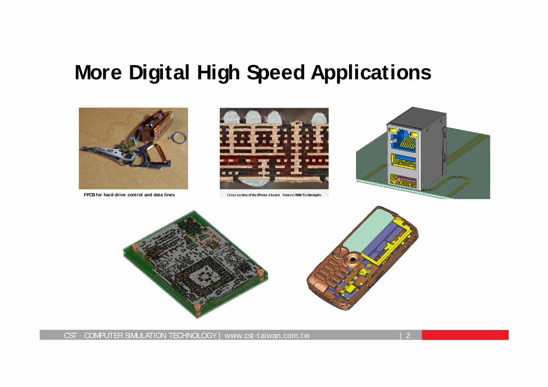
More Digital High Speed Applications
FPCB for hard-drive control and data lines
CST – COMPUTER SIMULATION TECHNOLOGY | www.cst-taiwan.com.tw | 3
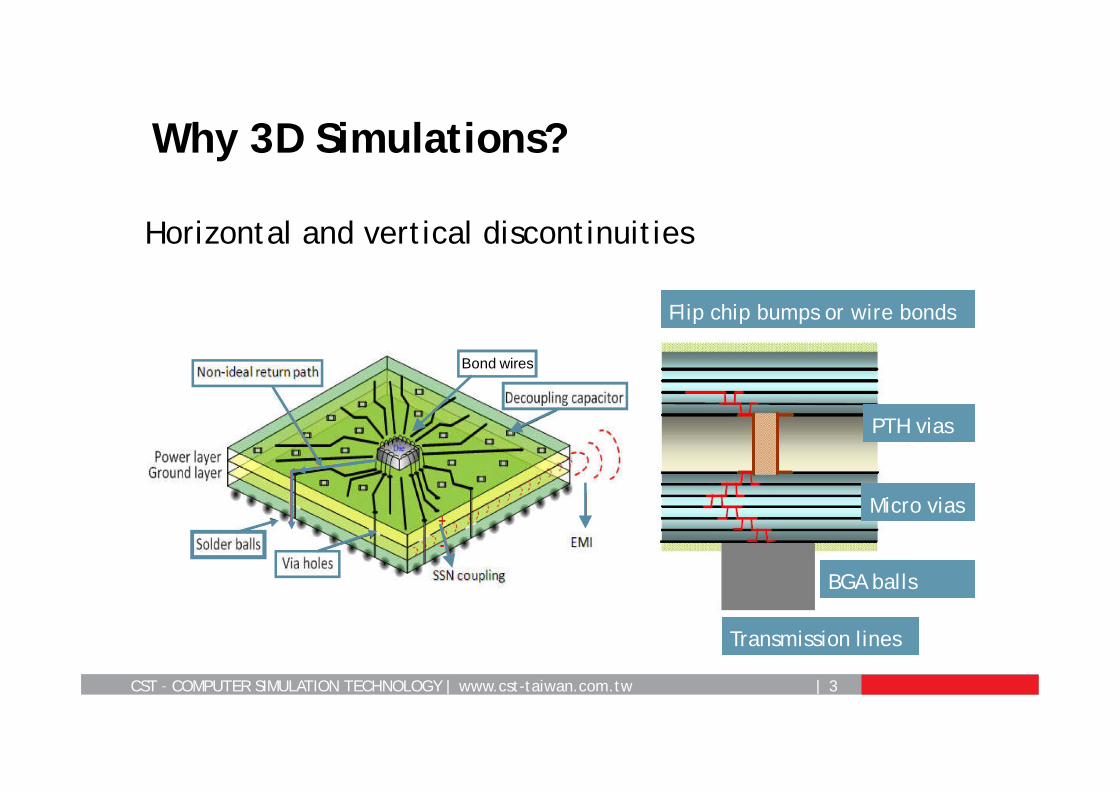
Why 3D Simulations?
Bond wires
Flip chip bumps or wire bonds
Transmission lines
Micro vias
PTH vias
BGA balls
Horizontal and vertical discontinuities
CST – COMPUTER SIMULATION TECHNOLOGY | www.cst-taiwan.com.tw | 4
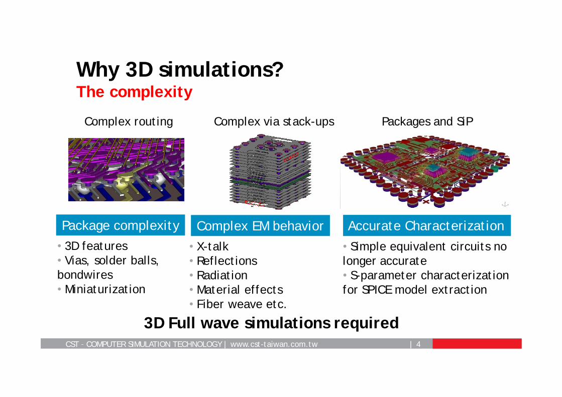
Why 3D simulations?The complexity
Accurate CharacterizationPackage complexity• 3D features• Vias, solder balls, bondwires • Miniaturization
Complex EM behavior• X-talk• Reflections• Radiation• Material effects• Fiber weave etc.
• Simple equivalent circuits no longer accurate• S-parameter characterization for SPICE model extraction
Complex routing Complex via stack-ups Packages and SiP
3D Full wave simulations required
CST – COMPUTER SIMULATION TECHNOLOGY | www.cst-taiwan.com.tw | 5
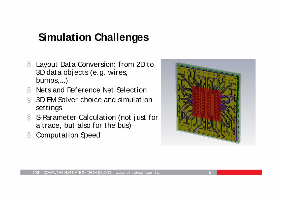
§ Layout Data Conversion: from 2D to 3D data objects (e.g. wires, bumps,…)
§ Nets and Reference Net Selection§ 3D EM Solver choice and simulation
settings§ S-Parameter Calculation (not just for
a trace, but also for the bus)§ Computation Speed
Simulation Challenges
CST – COMPUTER SIMULATION TECHNOLOGY | www.cst-taiwan.com.tw | 6
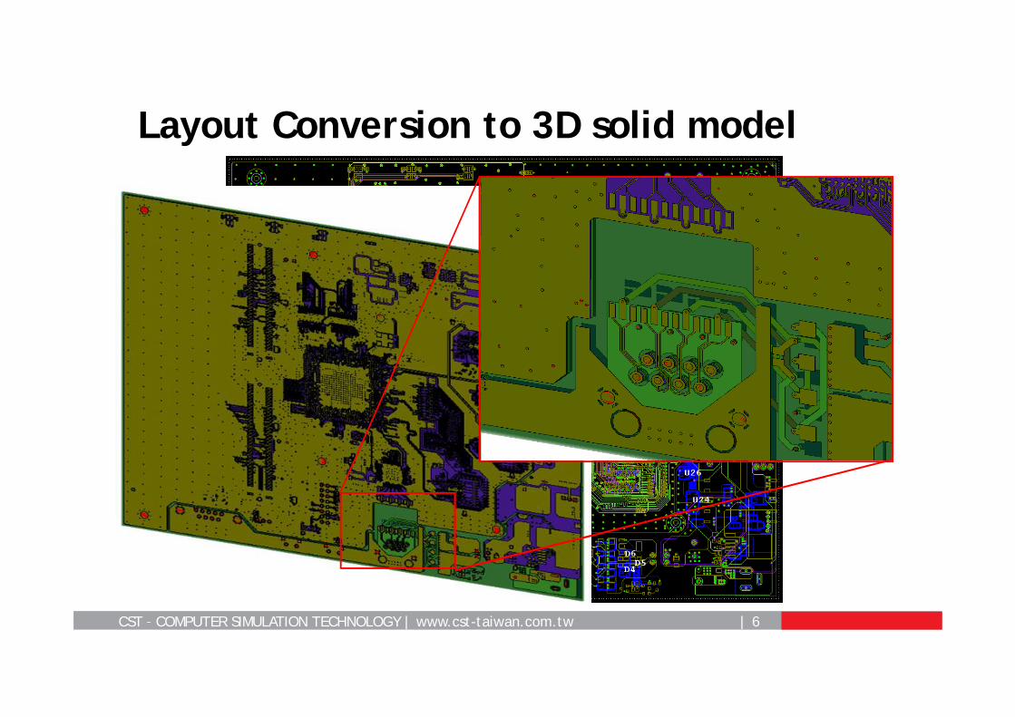
Layout Conversion to 3D solid model
CST – COMPUTER SIMULATION TECHNOLOGY | www.cst-taiwan.com.tw | 7
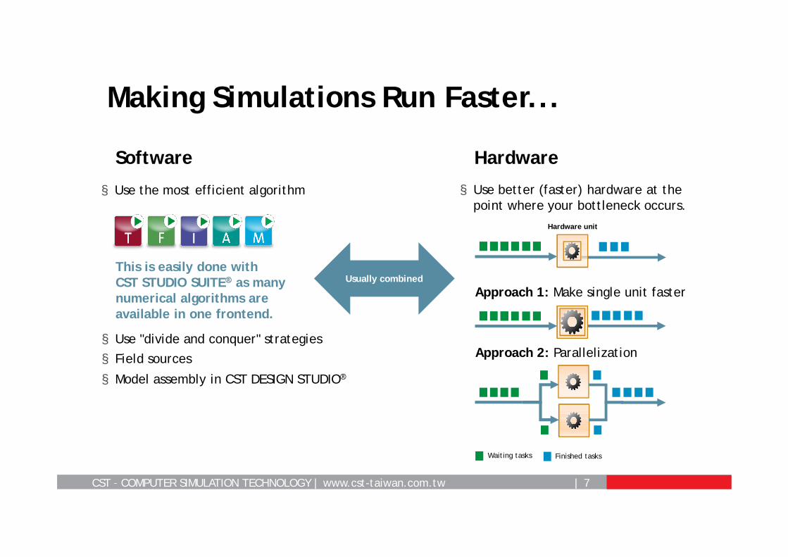
Making Simulations Run Faster...
Usually combined
Software Hardware
§ Use the most efficient algorithm § Use better (faster) hardware at the point where your bottleneck occurs.
This is easily done with CST STUDIO SUITE® as many numerical algorithms are available in one frontend.
Hardware unit
Approach 1: Make single unit faster
Approach 2: Parallelization
Waiting tasks Finished tasks
§ Use "divide and conquer" strategies
§ Field sources
§ Model assembly in CST DESIGN STUDIO®
CST – COMPUTER SIMULATION TECHNOLOGY | www.cst-taiwan.com.tw | 8
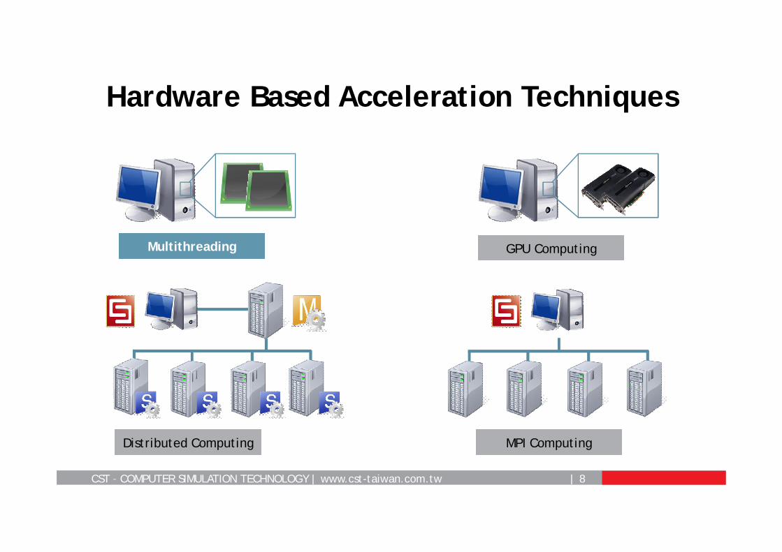
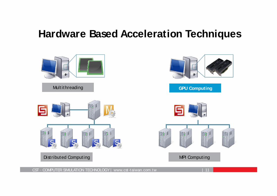
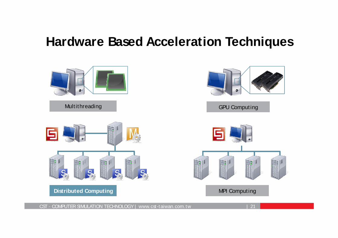
Hardware Based Acceleration Techniques
MPI ComputingDistributed Computing
GPU ComputingMultithreading
CST – COMPUTER SIMULATION TECHNOLOGY | www.cst-taiwan.com.tw | 9
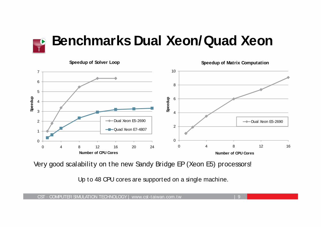
Benchmarks Dual Xeon/Quad Xeon
Very good scalability on the new Sandy Bridge EP (Xeon E5) processors!
Up to 48 CPU cores are supported on a single machine.
0
1
2
3
4
5
6
7
0 4 8 12 16 20 24
Spee
dup
Number of CPU Cores
Speedup of Solver Loop
Dual Xeon E5-2690
Quad Xeon E7-4807
0
2
4
6
8
10
0 4 8 12 16
Spee
dup
Number of CPU Cores
Speedup of Matrix Computation
Dual Xeon E5-2690
CST – COMPUTER SIMULATION TECHNOLOGY | www.cst-taiwan.com.tw | 10
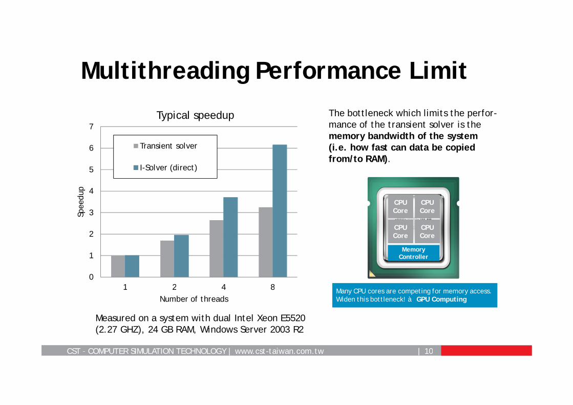
Multithreading Performance Limit
0
1
2
3
4
5
6
7
1 2 4 8
Spee
dup
Number of threads
Typical speedup
Transient solver
I-Solver (direct)
Measured on a system with dual Intel Xeon E5520 (2.27 GHZ), 24 GB RAM, Windows Server 2003 R2
The bottleneck which limits the perfor-mance of the transient solver is the memory bandwidth of the system (i.e. how fast can data be copied from/to RAM).
Memory Controller
CPU Core
CPU Core
CPU Core
CPU Core
Many CPU cores are competing for memory access.Widen this bottleneck! à GPU Computing
CST – COMPUTER SIMULATION TECHNOLOGY | www.cst-taiwan.com.tw | 11
Hardware Based Acceleration Techniques
GPU ComputingMultithreading
MPI ComputingDistributed Computing
CST – COMPUTER SIMULATION TECHNOLOGY | www.cst-taiwan.com.tw | 12
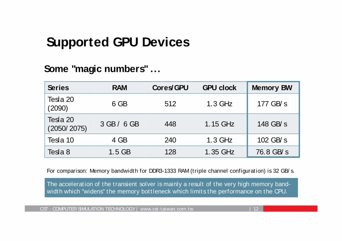
Supported GPU Devices
Series RAM Cores/GPU GPU clock Memory BW
Tesla 20(2090) 6 GB 512 1.3 GHz 177 GB/s
Tesla 20 (2050/2075) 3 GB / 6 GB 448 1.15 GHz 148 GB/s
Tesla 10 4 GB 240 1.3 GHz 102 GB/s
Tesla 8 1.5 GB 128 1.35 GHz 76.8 GB/s
Some "magic numbers" ...
For comparison: Memory bandwidth for DDR3-1333 RAM (triple channel configuration) is 32 GB/s.
The acceleration of the transient solver is mainly a result of the very high memory band-width which "widens" the memory bottleneck which limits the performance on the CPU.
CST – COMPUTER SIMULATION TECHNOLOGY | www.cst-taiwan.com.tw | 13
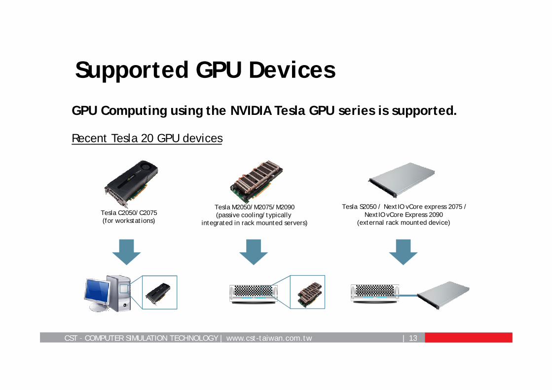
Supported GPU Devices
GPU Computing using the NVIDIA Tesla GPU series is supported.
Recent Tesla 20 GPU devices
Tesla S2050 / NextIO vCore express 2075 /NextIO vCore Express 2090
(external rack mounted device)Tesla C2050/C2075(for workstations)
Tesla M2050/M2075/M2090(passive cooling/typically
integrated in rack mounted servers)
CST – COMPUTER SIMULATION TECHNOLOGY | www.cst-taiwan.com.tw | 14
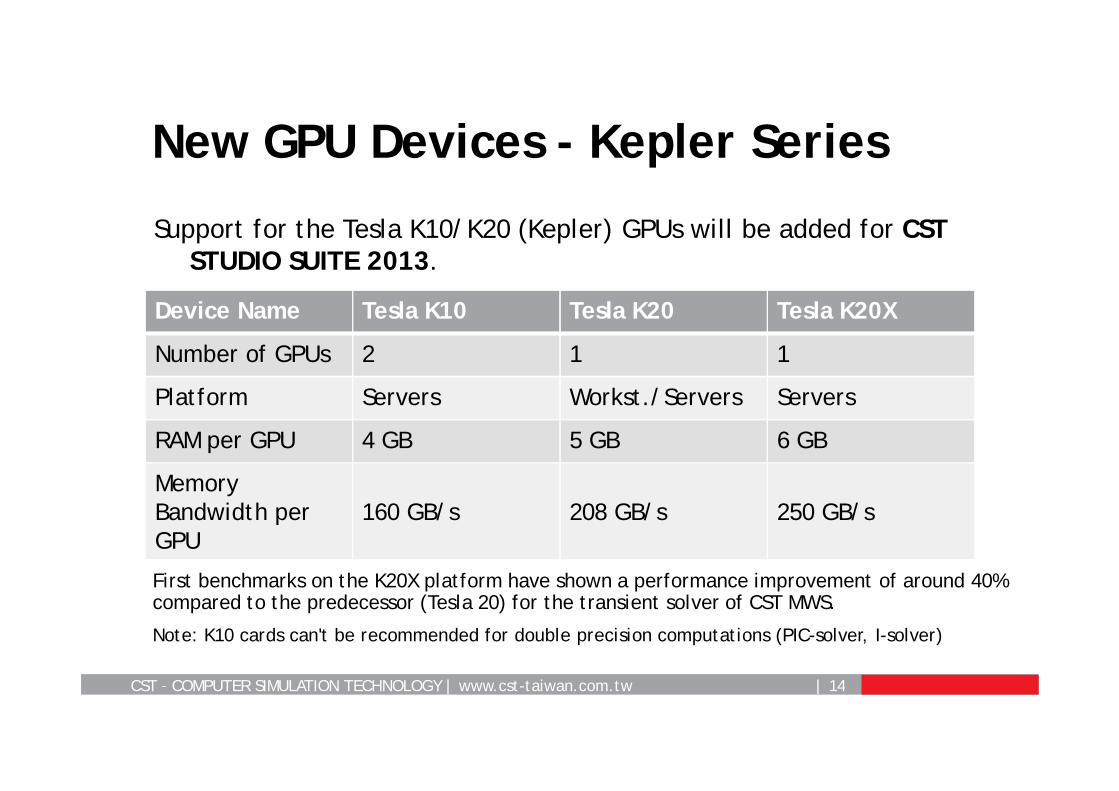
Support for the Tesla K10/K20 (Kepler) GPUs will be added for CST STUDIO SUITE 2013.
New GPU Devices - Kepler Series
Device Name Tesla K10 Tesla K20 Tesla K20X
Number of GPUs 2 1 1
Platform Servers Workst./Servers Servers
RAM per GPU 4 GB 5 GB 6 GB
Memory Bandwidth per GPU
160 GB/s 208 GB/s 250 GB/s
Note: K10 cards can't be recommended for double precision computations (PIC-solver, I-solver)
First benchmarks on the K20X platform have shown a performance improvement of around 40% compared to the predecessor (Tesla 20) for the transient solver of CST MWS.
CST – COMPUTER SIMULATION TECHNOLOGY | www.cst-taiwan.com.tw | 15
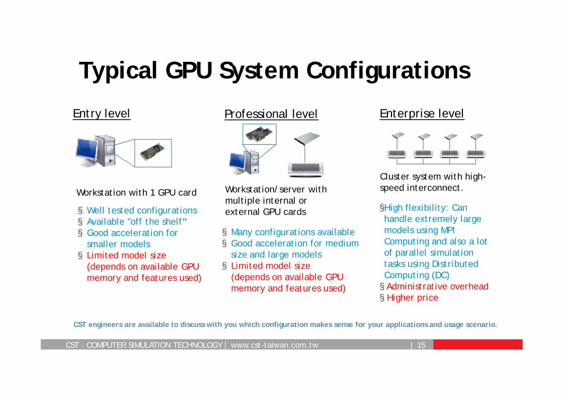
Typical GPU System Configurations
Entry level
Workstation with 1 GPU card
§ Well tested configurations§ Available "off the shelf“§ Good acceleration for
smaller models§ Limited model size
(depends on available GPU memory and features used)
Professional level
Workstation/server with multiple internal or external GPU cards
§ Many configurations available§ Good acceleration for medium
size and large models§ Limited model size
(depends on available GPU memory and features used)
Enterprise level
Cluster system with high-speed interconnect.
§High flexibility: Can handle extremely large models using MPI Computing and also a lot of parallel simulation tasks using Distributed Computing (DC)§ Administrative overhead§ Higher price
CST engineers are available to discuss with you which configuration makes sense for your applications and usage scenario.
CST – COMPUTER SIMULATION TECHNOLOGY | www.cst-taiwan.com.tw | 16
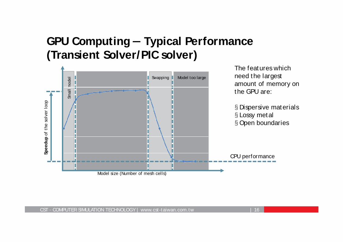
GPU Computing — Typical Performance (Transient Solver/PIC solver)
The features which need the largest amount of memory on the GPU are:
§ Dispersive materials§ Lossy metal§ Open boundaries
Model too largeSwapping
Smal
l mod
el
CPU performance
Model size (Number of mesh cells)
Spee
dup
of t
he s
olve
r lo
op
CST – COMPUTER SIMULATION TECHNOLOGY | www.cst-taiwan.com.tw | 17
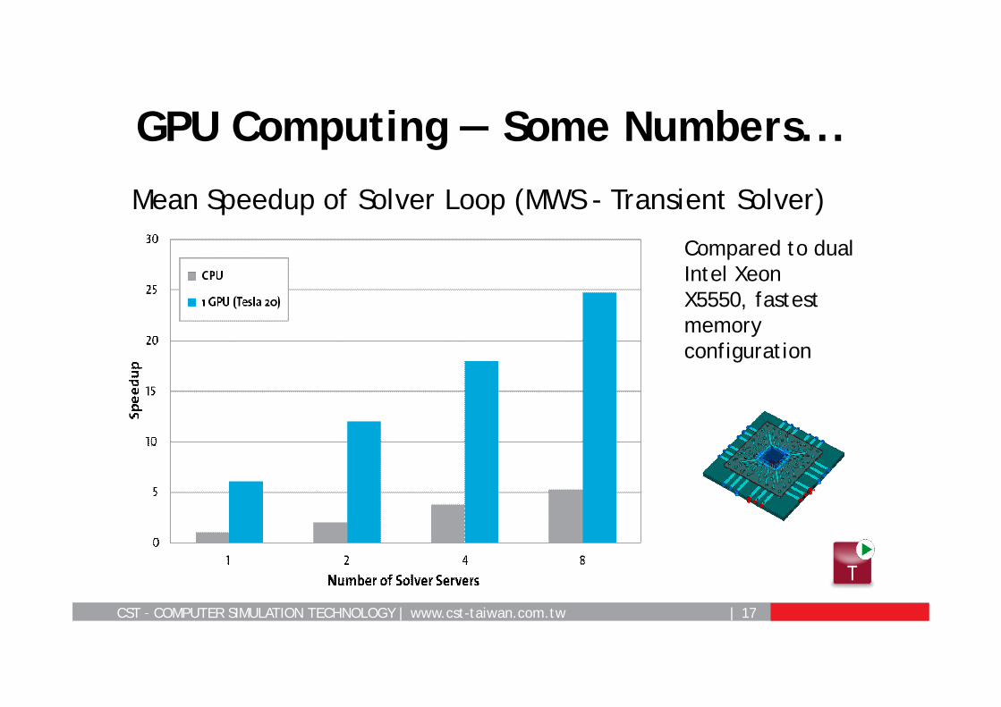
GPU Computing — Some Numbers...
Mean Speedup of Solver Loop (MWS - Transient Solver)
Compared to dual Intel Xeon X5550, fastest memory configuration
CST – COMPUTER SIMULATION TECHNOLOGY | www.cst-taiwan.com.tw | 18
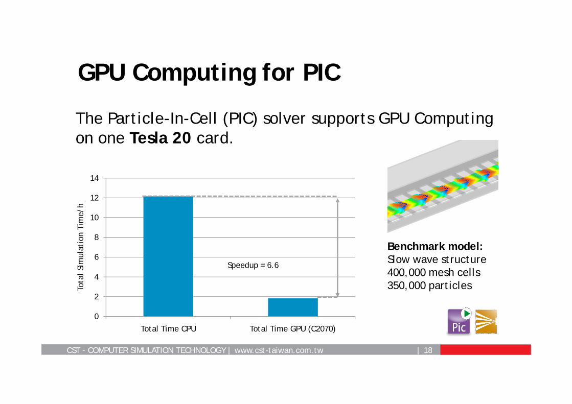
GPU Computing for PIC
The Particle-In-Cell (PIC) solver supports GPU Computing on one Tesla 20 card.
0
2
4
6
8
10
12
14
Total Time CPU Total Time GPU (C2070)
Tota
l Sim
ulat
ion
Tim
e/h
Speedup = 6.6
Benchmark model: Slow wave structure400,000 mesh cells350,000 particles
CST – COMPUTER SIMULATION TECHNOLOGY | www.cst-taiwan.com.tw | 19
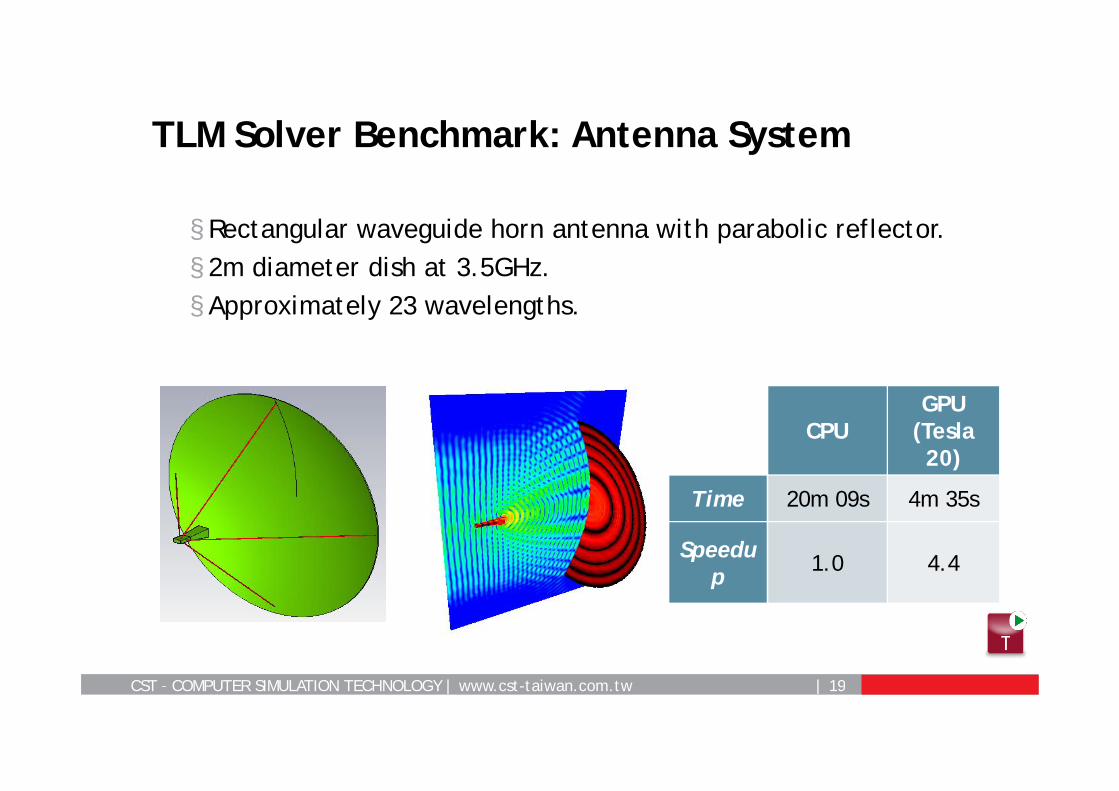
§ Rectangular waveguide horn antenna with parabolic reflector.§ 2m diameter dish at 3.5GHz.§ Approximately 23 wavelengths.
TLM Solver Benchmark: Antenna System
CPUGPU
(Tesla20)
Time 20m 09s 4m 35s
Speedup 1.0 4.4
CST – COMPUTER SIMULATION TECHNOLOGY | www.cst-taiwan.com.tw | 20
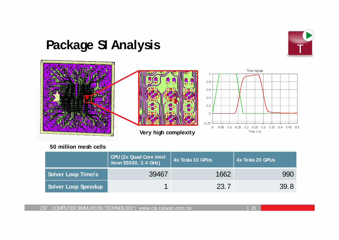
Package SI Analysis
50 million mesh cells
Very high complexity
CPU (2x Quad Core Intel Xeon E5530, 2.4 GHz) 4x Tesla 10 GPUs 4x Tesla 20 GPUs
Solver Loop Time/s 39467 1662 990
Solver Loop Speedup 1 23.7 39.8
CST – COMPUTER SIMULATION TECHNOLOGY | www.cst-taiwan.com.tw | 21
Hardware Based Acceleration Techniques
MPI ComputingDistributed Computing
GPU ComputingMultithreading
CST – COMPUTER SIMULATION TECHNOLOGY | www.cst-taiwan.com.tw | 22
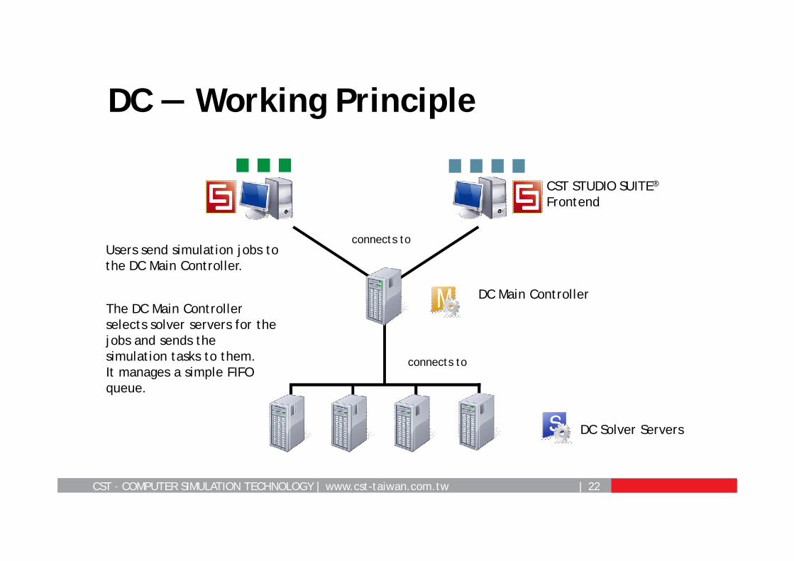
DC — Working Principle
Users send simulation jobs to the DC Main Controller.
The DC Main Controller selects solver servers for the jobs and sends the simulation tasks to them.It manages a simple FIFO queue.
CST STUDIO SUITE®
Frontend
connects to
connects to
DC Main Controller
DC Solver Servers
CST – COMPUTER SIMULATION TECHNOLOGY | www.cst-taiwan.com.tw | 23
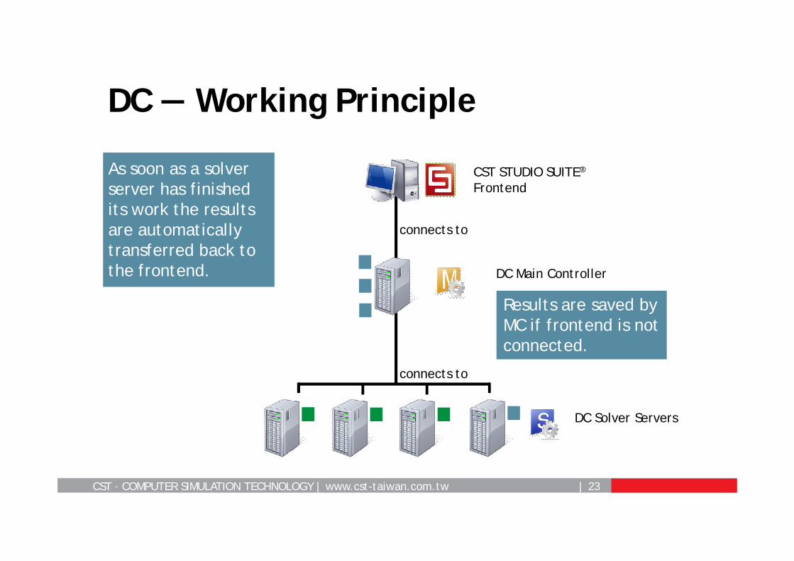
DC — Working Principle
As soon as a solver server has finished its work the results are automatically transferred back to the frontend.
connects to
connects to
DC Main Controller
DC Solver Servers
Results are saved by MC if frontend is not connected.
CST STUDIO SUITE®
Frontend
CST – COMPUTER SIMULATION TECHNOLOGY | www.cst-taiwan.com.tw | 24
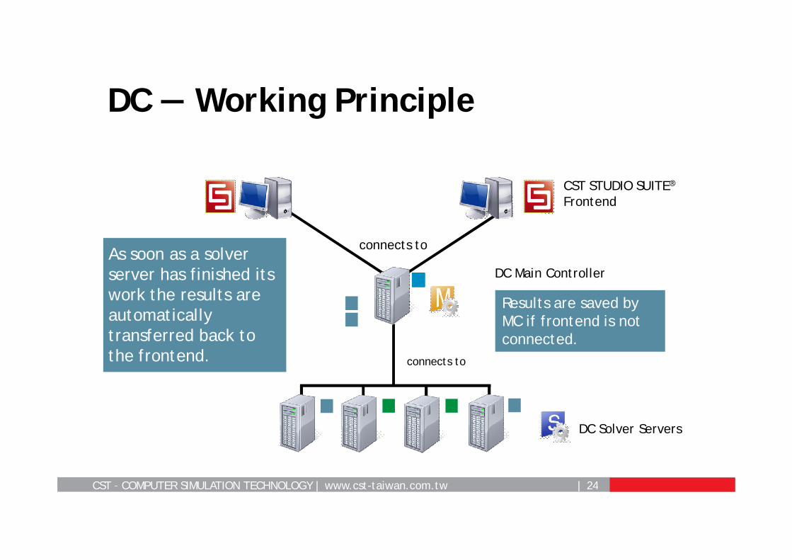
DC — Working Principle
CST STUDIO SUITE®
Frontend
connects to
connects to
DC Solver Servers
As soon as a solver server has finished its work the results are automatically transferred back to the frontend.
DC Main Controller
Results are saved by MC if frontend is not connected.
CST – COMPUTER SIMULATION TECHNOLOGY | www.cst-taiwan.com.tw | 25
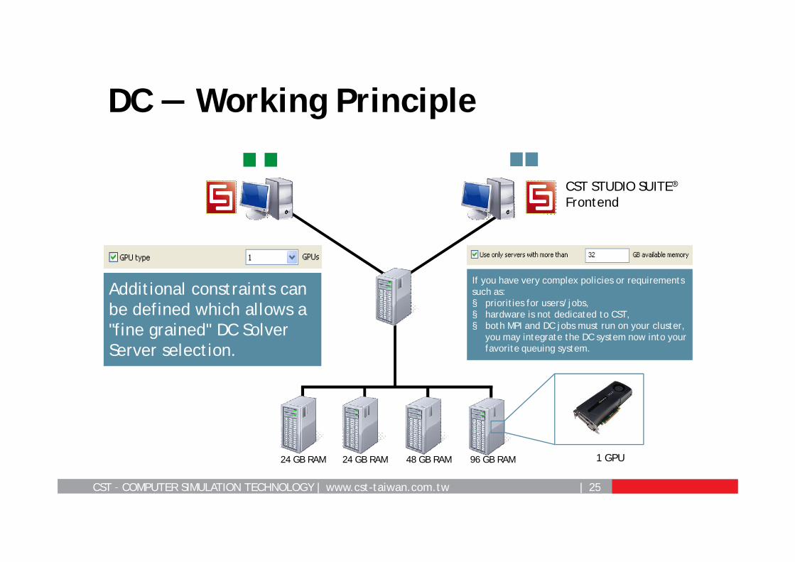
DC — Working Principle
CST STUDIO SUITE®
Frontend
Additional constraints can be defined which allows a "fine grained" DC Solver Server selection.
If you have very complex policies or requirements such as: § priorities for users/jobs,§ hardware is not dedicated to CST,§ both MPI and DC jobs must run on your cluster,
you may integrate the DC system now into your favorite queuing system.
1 GPU24 GB RAM 24 GB RAM 48 GB RAM 96 GB RAM
CST – COMPUTER SIMULATION TECHNOLOGY | www.cst-taiwan.com.tw | 26
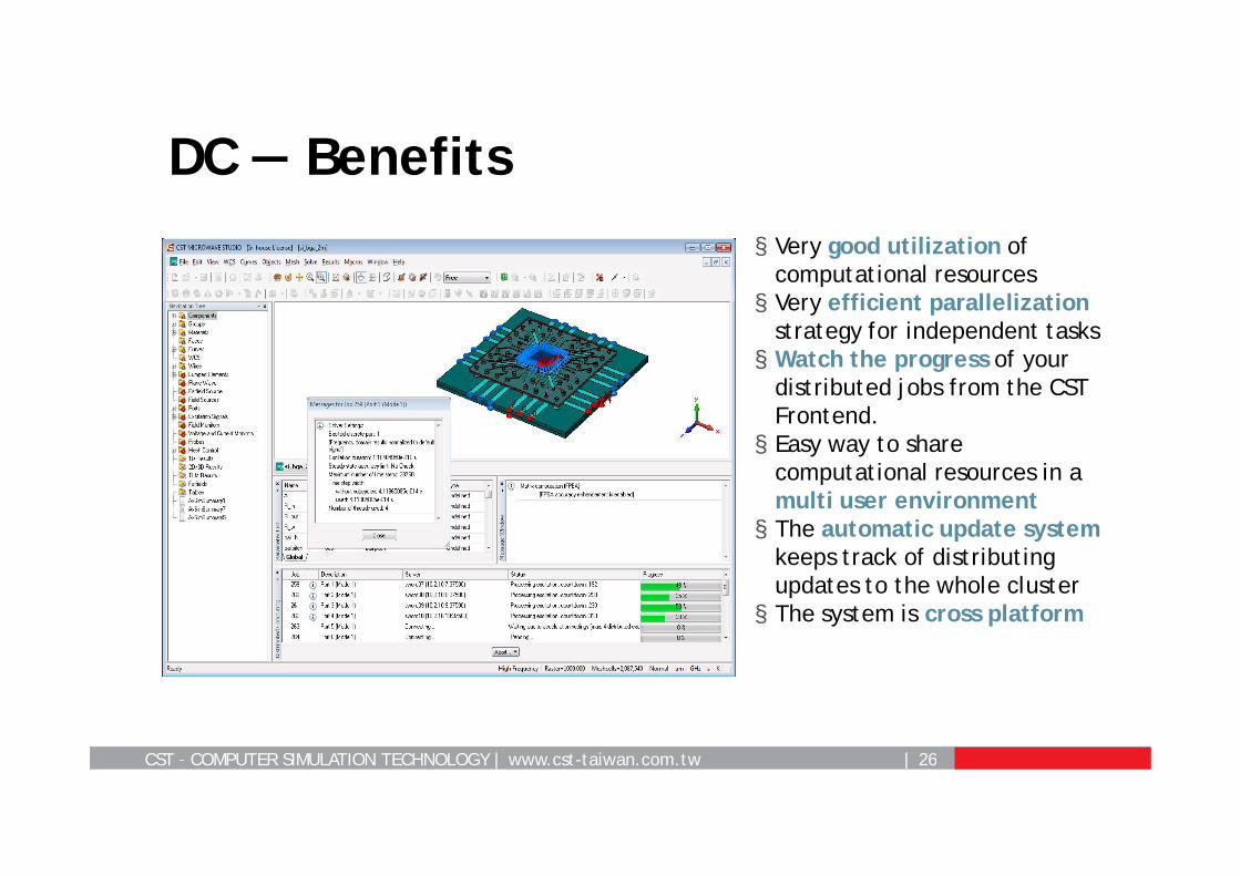
DC — Benefits§ Very good utilization of
computational resources§ Very efficient parallelization
strategy for independent tasks§ Watch the progress of your
distributed jobs from the CST Frontend.§ Easy way to share
computational resources in a multi user environment§ The automatic update system
keeps track of distributing updates to the whole cluster§ The system is cross platform
CST – COMPUTER SIMULATION TECHNOLOGY | www.cst-taiwan.com.tw | 27
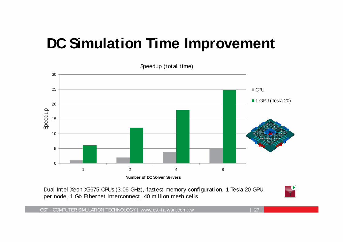
DC Simulation Time Improvement
0
5
10
15
20
25
30
1 2 4 8
Spee
dup
Number of DC Solver Servers
Speedup (total time)
CPU
1 GPU (Tesla 20)
Dual Intel Xeon X5675 CPUs (3.06 GHz), fastest memory configuration, 1 Tesla 20 GPU per node, 1 Gb Ethernet interconnect, 40 million mesh cells
CST – COMPUTER SIMULATION TECHNOLOGY | www.cst-taiwan.com.tw | 28
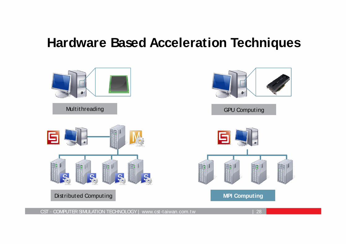
Hardware Based Acceleration Techniques
MPI ComputingDistributed Computing
GPU ComputingMultithreading
CST – COMPUTER SIMULATION TECHNOLOGY | www.cst-taiwan.com.tw | 29
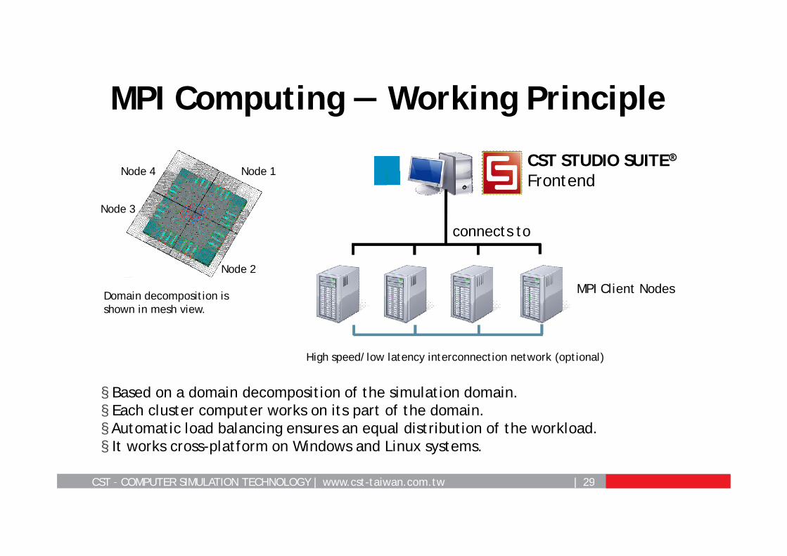
MPI Computing — Working Principle
§ Based on a domain decomposition of the simulation domain.§ Each cluster computer works on its part of the domain.§ Automatic load balancing ensures an equal distribution of the workload. § It works cross-platform on Windows and Linux systems.
Domain decomposition is shown in mesh view.
Node 2
Node 3
Node 4 Node 1
connects to
MPI Client Nodes
CST STUDIO SUITE®Frontend
High speed/low latency interconnection network (optional)

CST – COMPUTER SIMULATION TECHNOLOGY | www.cst-taiwan.com.tw | 30
Message Passing Interface (MPI)-based parallelization ofCST MWS-T Solver (Windows and Linux)
CST Simulation Acceleration:Cluster Computing (MPI)
§ Multiple workstations in parallel
§ Problem size: up to billions of unknowns
CST – COMPUTER SIMULATION TECHNOLOGY | www.cst-taiwan.com.tw | 31
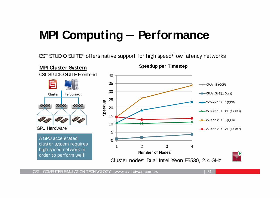
MPI Computing — Performance
CST STUDIO SUITE® offers native support for high speed/low latency networks
A GPU accelerated cluster system requires high-speed network in order to perform well!
MPI Cluster SystemCST STUDIO SUITE Frontend
GPU Hardware
Cluster Interconnect
0
0.5
1
1.5
2
2.5
3
3.5
4
1 2 3 4
Spee
dup
Number of Nodes
Speedup per Timestep
CPU / IB (QDR)
CPU / GbE (1 Gb/s)
0
5
10
15
20
25
30
1 2 3 4
Spee
dup
Number of Nodes
Speedup per Timestep
CPU / IB (QDR)
CPU / GbE (1 Gb/s)
2xTesla 10 / IB (QDR)
2xTesla 10 / GbE (1 Gb/s)
0
5
10
15
20
25
30
35
40
1 2 3 4
Spee
dup
Number of Nodes
Speedup per Timestep
CPU / IB (QDR)
CPU / GbE (1 Gb/s)
2xTesla 10 / IB (QDR)
2xTesla 10 / GbE (1 Gb/s)
2xTesla 20 / IB (QDR)
2xTesla 20 / GbE (1 Gb/s)
Cluster nodes: Dual Intel Xeon E5530, 2.4 GHz
CST – COMPUTER SIMULATION TECHNOLOGY | www.cst-taiwan.com.tw | 32
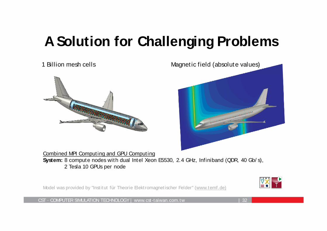
A Solution for Challenging Problems
Combined MPI Computing and GPU ComputingSystem: 8 compute nodes with dual Intel Xeon E5530, 2.4 GHz, Infiniband (QDR, 40 Gb/s),
2 Tesla 10 GPUs per node
Model was provided by "Institut für Theorie Elektromagnetischer Felder" (www.temf.de)
1 Billion mesh cells Magnetic field (absolute values)
CST – COMPUTER SIMULATION TECHNOLOGY | www.cst-taiwan.com.tw | 33
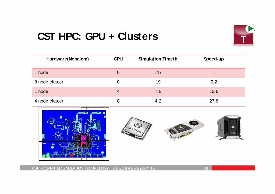
CST HPC: GPU + Clusters
Hardware(Nehalem) GPU Simulation Time/h Speed-up
1 node 0 117 1
8 node cluster 0 19 5.2
1 node 4 7.5 15.6
4 node cluster 8 4.2 27.8
CST – COMPUTER SIMULATION TECHNOLOGY | www.cst-taiwan.com.tw | 34
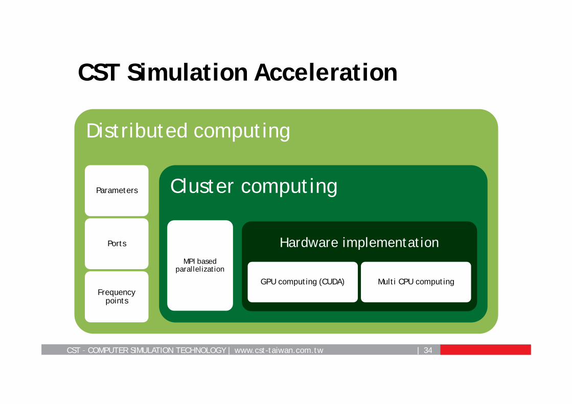
CST Simulation Acceleration
Distributed computing
Parameters
Ports
Frequency points
Cluster computing
MPI based parallelization
Hardware implementation
GPU computing (CUDA) Multi CPU computing


