ENGINEERING GUIDE fi U.S. Registered Trademark ' 2004 Honeywell International Inc. All Rights Reserved 63-2623 Direct Coupled Actuators Actuator Selection Deciding what actuator will best fit your damper needs can seem like a difficult task. However, these quick steps will help you find the actuator you need quickly and effectively. Use the procedure detailed below to find the total torque requirements in pound-inches (lb-in.) and then proceed to the following pages for simple questions to help select the proper model to best suit your application. STANDARD ACTUATOR SIZING 1. Determine the Rated Torque Loading (lb-in. per sq ft): a. If the manufacturer-specified rated torque loading is known, enter that in Table 2. b. If the manufacturer-specified rated torque loading is unknown, use Table 1. 2. Enter this value in Table 2. 3. Determine Damper Area (sq ft): a. For round dampers, use the equation: b. For rectangular dampers use the equation: NOTE: 144 sq in. = 1 sq ft 4. Enter the damper area value in Table 2. Table 1. Rated Torque Loading Determination. a Assumes pressure differential of less than or equal to 2 in. w.c. For larger differentials, consult the damper manufacturer. Table 2. Torque Requirements Calculation. x / 144 = π r 2 × 144 ------------- length width × ( ) 144 --------------------------------------- Rated Torque (lb-in. per sq ft) Air Velocity feet per minute (fpm) a Parallel Blades Opposed Blades Round Damper With Seals Without Seals With Seals Without Seals up to 1000 7 4 5 3 10 1000-2500 10.5 6 7.5 4.5 14 2500-3500 14 8 10 6 20 Rated Torque Loading lb-in. per sq ft x Damper Area sq ft = NOTE: Honeywell recommends adding 20 percent safety factors x 1.20 Total Required Torque (lb-in.) =
Actuator SelectionDeciding what actuator will best fit your damper needs can seem like a difficult task. However, these quick steps will help you find the actuator you need quickly and effectively.
Use the procedure detailed below to find the total torque requirements in pound-inches (lb-in.) and then proceed to the following pages for simple questions to help select the proper model to best suit your application.
STANDARD ACTUATOR SIZING1. Determine the Rated Torque Loading (lb-in. per sq ft):
a. If the manufacturer-specified rated torque loading is known, enter that in Table 2.
b. If the manufacturer-specified rated torque loading is unknown, use Table 1.
2. Enter this value in Table 2.3. Determine Damper Area (sq ft):
a. For round dampers, use the equation: b. For rectangular dampers
use the equation:
NOTE: 144 sq in. = 1 sq ft
4. Enter the damper area value in Table 2.
Table 1. Rated Torque Loading Determination.
a Assumes pressure differential of less than or equal to 2 in. w.c. For larger differentials, consult the damper manufacturer.
Rated Torque (lb-in. per sq ft)Air Velocity feet per minute (fpm)a
Parallel Blades Opposed Blades Round DamperWith
SealsWithout Seals
With Seals
Without Seals
up to 1000 7 4 5 3 101000-2500 10.5 6 7.5 4.5 142500-3500 14 8 10 6 20
Rated Torque Loading lb-in. per sq ft x
Damper Area sq ft =
NOTE: Honeywell recommends adding 20 percent safety factors x 1.20
Total Required Torque (lb-in.) =
ACTUATOR SELECTION
63-2623 2
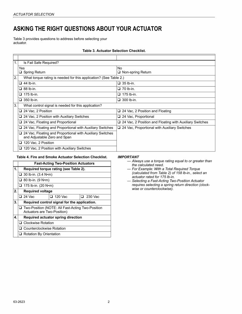
ASKING THE RIGHT QUESTIONS ABOUT YOUR ACTUATORTable 3 provides questions to address before selecting your actuator.
Table 3. Actuator Selection Checklist.
Table 4. Fire and Smoke Actuator Selection Checklist. IMPORTANT� Always use a torque rating equal to or greater than
the calculated need.� For Example: With a Total Required Torque
(calculated from Table 2) of 158 lb-in., select an actuator rated for 175 lb-in.
� Selecting a Fast-Acting Two-Position Actuator requires selecting a spring return direction (clock-wise or counterclockwise).
1. Is Fail Safe Required?Yes! Spring Return
No! Non-spring Return
2. What torque rating is needed for this application? (See Table 2.)! 44 lb-in. ! 35 lb-in.! 88 lb-in. ! 70 lb-in.! 175 lb-in. ! 175 lb-in.! 350 lb-in. ! 300 lb-in.
3. What control signal is needed for this application?! 24 Vac, 2 Position ! 24 Vac, 2 Position and Floating! 24 Vac, 2 Position with Auxiliary Switches ! 24 Vac, Proportional! 24 Vac, Floating and Proportional ! 24 Vac, 2 Position and Floating with Auxiliary Switches! 24 Vac, Floating and Proportional with Auxiliary Switches ! 24 Vac, Proportional with Auxiliary Switches! 24 Vac, Floating and Proportional with Auxiliary Switches
and Adjustable Zero and Span ! 120 Vac, 2 Position! 120 Vac, 2 Position with Auxiliary Switches
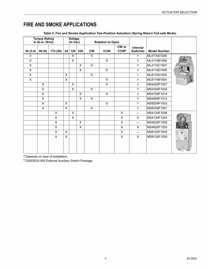
Fast-Acting Two-Position Actuators1. Required torque rating (see Table 2).
X X X b ML4115A1009X X X b ML4115B1008X X X b ML4115C1007X X X b ML4115D1006X X X b ML8115A1005X X X b ML8115B1004
X X X b MS4209F1007X X X b MS4309F1005X X X b MS4709F1014X X X b MS4809F1012X X X b MS8209F1003X X X b MS8309F1001
X X X � MS4120F1006X X X X MS4120F1204X X X � MS4620F1005X X X X MS4620F1203X X X � MS8120F1002X X X X MS8120F1200
ACTUATOR SELECTION
63-2623 4
ACTUATOR FEATURESUse Table 6 to determine what features best fit your actuator needs. For more information on actuators, see the Product Data or Specification Data literature for the corresponding actuator.
Table 6. Actuator Features.
Fail Safe Mode Torque Rating Voltage
Control Signal
Special Features
Sprin
g R
etur
n
Non
-Spr
ing
Ret
urn
35 lb
-in. (
4 N
�m)
44 lb
-in. (
5 N
�m)
70 lb
-in. (
8 N
�m)
88 lb
-in. (
10 N
�m)
175
lb-in
. (20
N�m
)
300
lb-in
. (34
N�m
)
24 V
ac
100-
200
Vac
Two
Posi
tion
Floa
ting
Prop
ortio
nal
Switc
hes
Adj
usta
ble
Zero
and
Spa
n
Model Number Catalog NumberX X X X MS8105A1008 S0524-2POSX X X X MS4105A1002 S05120-2POSX X X X X MS7505A2008 S05010X X X X MS8110A1008 S1024-2POSX X X X X MS8110A1206 S1024-2POS-SW2X X X X MS4110A1002 S10120-2POSX X X X X MS4110A1200 S10120-2POS-SW2X X X X X MS7510A2008 S10010X X X X X X MS7510A2206 S10010-SW2X X X X X X MS7510H2209 S10010-SER-SW2X X X X MS8120A1007 S2024-2POSX X X X X MS8120A1205 S2024-2POS-SW2X X X X MS4120A1001 S20120-2POSX X X X X MS4120A1209 S20120-2POS-SW2X X X X X MS7520A2007 S20010X X X X X X MS7520A2205 S20010-SW2X X X X X X MS7520H2208 S20010-SER-SW2
X X X X X ML6161B2024 ML6161B2024X X X X ML7161A2008 ML7161A2008
X X X X X ML6174B2019 ML6174B2019X X X X ML7174A2001 ML7174A2201
X X X X X MN6120A1002 N2024X X X X X X MN6120A1200 N2024-SW2X X X X MN7220A2007 N20010X X X X X MN7220A2205 N20010-SW2X X X X X MN6134A1003 N3424X X X X MN7234A2008 N344010
CRANK ARM LINKAGES
5 63-2623
Crank Arm LinkagesAPPLICATIONSome installations physically prohibit direct coupling the actuator to the damper shaft. Direct-coupled mounting is preferable. Remote mounting of Honeywell Direct Coupled Actuators (DCA) can be done using a damper linkage.
This section discusses damper linkage installations, how to install a damper linkage and explanations of special applications, including:� Modification of damper linkages to achieve faster response
times at the damper.� Modification of damper linkages so that the angle of
rotation can be limited.
Installation examples that can prohibit direct-coupled mounting:� Dampers installed in a wall section.� Dampers installed inside a roof-top unit with no room left
outside the damper frame.� Replacing foot-mounted motor(s).� Dampers without provision for external damper shaft.
DAMPER LINKAGEA basic damper linkage includes a damper shaft crankarm, an actuator crankarm, a pushrod, and ball joints. In addition, a DCA can require a remote mounting kit such as Honeywell�s part number 50001194-001. This kit allows the actuator to be mounted to either the duct or the damper frame.
IMPORTANT� The actuator crankarm must be able to complete its
full stroke unobstructed.� The actuator travel limits must correspond to the
damper full open or full closed position.� Short pushrods can be difficult to adjust.� Lengthy pushrods often lack rigidity, resulting in poor
damper response.
EXTERNAL VS. INTERNAL MOUNTINGInstallation can require the actuator mounting to be either external or internal to the damper frame. In most cases, this corresponds to external or internal to the ductwork.
Damper Crankarms
ExternalExternal mounting requires fitting the damper shaft with a crankarm and a ball joint. One crankarm is Honeywell�s part number 26026G.
Fig. 1. 26026G Crankarm.
InternalInternal mounting requires fitting the damper blade with a damper blade lever. It is typical to order the damper with a factory-installed blade lever.
If the damper is not already fitted with a blade lever, use Honeywell part number 32007205-002 (for dampers less than 24 in. high) or 32007205-003 (for dampers greater than 24 in. high). See Fig. 2.
CRANK ARM LINKAGES
63-2623 6
Fig. 2. Damper blade levers.
Actuator CrankarmsDepending upon the installation, the actuator crankarm might be part of a remote mounting kit, such as the 50001194-001. It can also be an independent part, such as the 205830A. In either case, fit the actuator with a crankarm and balljoint.
Ball JointsEach crankarm requires a balljoint to facilitate connection between the damper and actuator. Honeywell part number 27518 is sized for 5/16 in. diameter pushrods and 103598 is sized for 1/4 in. diameter pushrods.
Fig. 3. 27518 Balljoint.
PushrodsConnecting the damper shaft crankarm and the actuator crankarm requires a pushrod. The pushrod connects to the balljoint of each crankarm. Pushrods, such as Honeywell part number 25720, can be ordered in various lengths or cut to length by the installer. 25720 is a 5/16 in. diameter rod.
Table 7. Suggested Parts List
M20861 M20860
32007205-002 shown32007205-003 shown
Mounting Type External InternalDamper Crankarm 26026G 32007205-002 or -003Ball Joints 27518 (5/16 in. diameter) 27518 (5/16 in. diameter)Pushrod 25720x (5/16 in. diameter) 25720x (5/16 in. diameter)Actuator Crankarm 50001194-001 Foot/Frame Mounting Kit, or see
actuator accessories for appropriate crankarm50001194-001 Foot/Frame Mounting Kit, or see actuator accessories for appropriate crankarm
CRANK ARM LINKAGES
7 63-2623
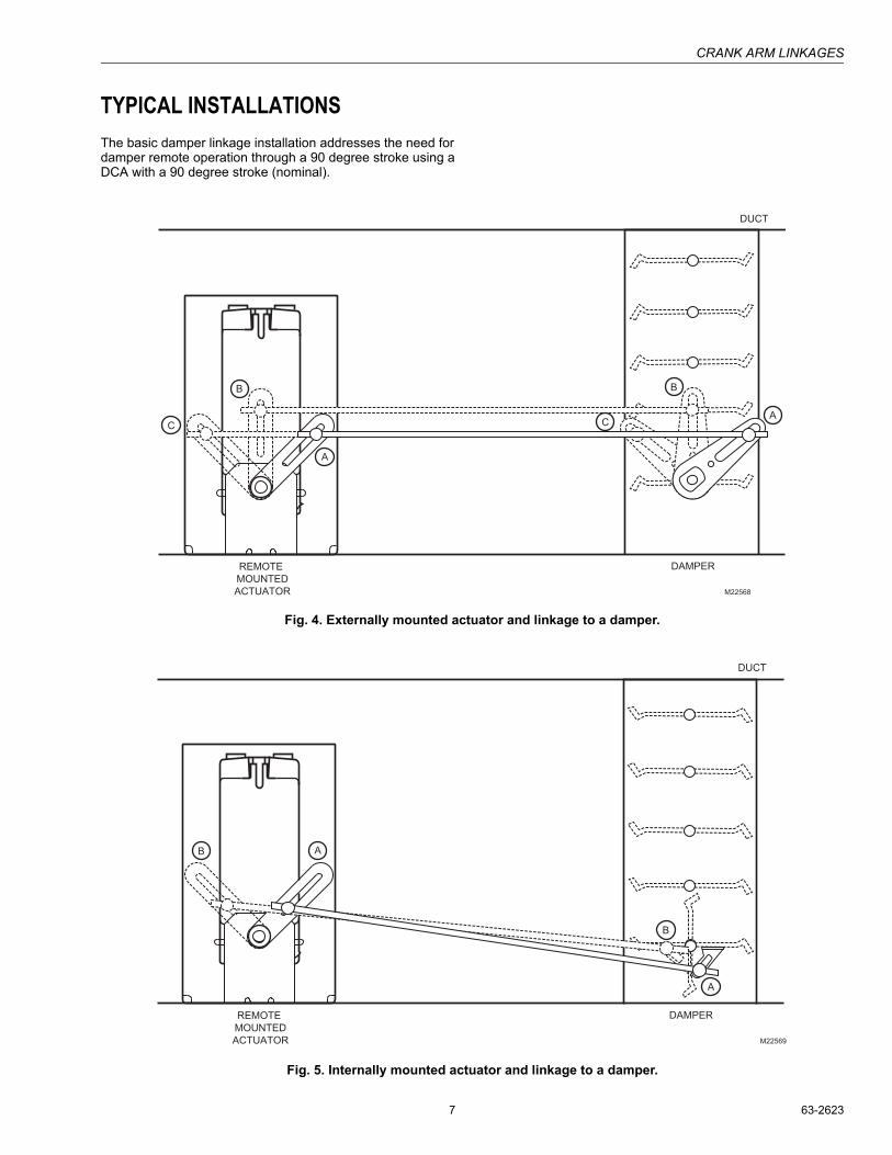
TYPICAL INSTALLATIONSThe basic damper linkage installation addresses the need for damper remote operation through a 90 degree stroke using a DCA with a 90 degree stroke (nominal).
Fig. 4. Externally mounted actuator and linkage to a damper.
Fig. 5. Internally mounted actuator and linkage to a damper.
M22568
C
REMOTE
MOUNTED
ACTUATOR
A
DAMPER
DUCT
B
CA
B
M22569
B
REMOTE
MOUNTED
ACTUATOR
A
DAMPER
DUCT
B
A
CRANK ARM LINKAGES
63-2623 8
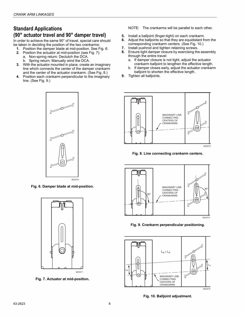
Standard Applications(90° actuator travel and 90° damper travel)In order to achieve the same 90° of travel, special care should be taken in deciding the position of the two crankarms:
1. Position the damper blade at mid-position. See Fig. 6.2. Position the actuator at mid-position (see Fig. 7):
a. Non-spring return: Declutch the DCA.b. Spring return: Manually wind the DCA.
3. With the actuator mounted in place, create an imaginary line which connects the center of the damper crankarm and the center of the actuator crankarm. (See Fig. 8.)
4. Position each crankarm perpendicular to the imaginary line. (See Fig. 9.)
NOTE: The crankarms will be parallel to each other.
5. Install a balljoint (finger-tight) on each crankarm.6. Adjust the balljoints so that they are equidistant from the
corresponding crankarm centers. (See Fig. 10.)7. Install pushrod and tighten retaining screws.8. Ensure tight damper closure by exercising the assembly
through the entire travel:a. If damper closure is not tight, adjust the actuator
crankarm balljoint to lengthen the effective length.b. If damper closes early, adjust the actuator crankarm
balljoint to shorten the effective length.9. Tighten all balljoints.
Fig. 6. Damper blade at mid-position.
Fig. 7. Actuator at mid-position.
Fig. 8. Line connecting crankarm centers.
Fig. 9. Crankarm perpendicular positioning.
Fig. 10. Balljoint adjustment.
M22570
M22571
M22572
IMAGINARY LINE
CONNECTING
CENTERS OF
CRANKARMS
M22573
90°
90°IMAGINARY LINE
CONNECTING
CENTERS OF
CRANKARMS
M22574
La
La = Ld
Ld
IMAGINARY LINE
CONNECTING
CENTERS OF
CRANKARMS
CRANK ARM LINKAGES
9 63-2623
Non-Standard Applications
Faster Response TimeSome applications require faster than normal actuator response time. It is possible to configure a linkage to cause faster damper travel than actuator stroke.
Limited Damper TravelSome applications require limiting damper travel (to less than 90 degrees). It is possible to configure a linkage to cause less damper travel than actuator stroke.
NOTE: With some actuators, travel limitation can be achieved using mechanical travel limits.
Non-Standard Application SetupSetup is the same for both faster response time and limited damper travel. To accomplish either, the effective crankarm length must be adjusted. As with all crankarm applications the two variables, crankarm angle and length are critical.
1. Follow standard application steps 1 through 5.2. Adjust the crankarm effective lengths to achieve faster
timing or limited travel.
NOTES:� Many variations are possible using this basic
guideline.� Experimentation is typically necessary to achieve
the required travel/timing.
Fig. 11. Limited travel dynamics. (Shown with both actuator and damper at mid-position.)
With crankarms parallel at mid-position the difference in effective crankarm lengths is inversely proportional to:� the difference in full rotation angles.� the difference in timing.
EXAMPLE: La is twice the length of Ld. (See Fig. 11.)� Travel of the damper is half that of the actuator.� Control is more precise.
Fig. 12. Faster timing. (Shown with both actuator and damper at mid-position.)
EXAMPLE: La is half the length of Ld. (See Fig. 12.)� Damper timing is half that of the actuator.
M22575
La
La > Ld
Ld
PUSHROD
IMAGINARY LINE
CONNECTING
CENTERS OF
CRANKARMS
ACTUATOR TRAVELS 90° IN 90 SECONDS.
DAMPER TRAVELS LESS THAN 90° IN 90 SECONDS, DEPENDING
UPON THE LENGTH OF THE DAMPER CRANKARM RELATIVE TO THE
LENGTH OF THE ACTUATOR CRANKARM.
1
2
12
M22576
La
La < Ld
Ld
PUSHROD
ACTUATOR TRAVELS 90° IN 90 SECONDS.
DAMPER TRAVELS LESS THAN 90° IN 90 SECONDS, DEPENDING
UPON THE LENGTH OF THE DAMPER CRANKARM RELATIVE TO THE
LENGTH OF THE ACTUATOR CRANKARM.
1
2
IMAGINARY LINE
CONNECTING
CENTERS OF
CRANKARMS
1 2
CRANK ARM LINKAGES
63-2623 10
NOTES
CRANK ARM LINKAGES
11 63-2623
63-2623 B.B. 11-04 www.honeywell.com
Automation and Control SolutionsHoneywell International Inc. Honeywell Limited-Honeywell Limitée1985 Douglas Drive North 35 Dynamic DriveGolden Valley, MN 55422 Scarborough, Ontario