W. Miller, J. Kosny, T. Stovall, A. Karagiozis D. Yarbrough, A. Desjarlais High Performance Roofs How to Beat the Heat Building Envelope Program Oak Ridge National Laboratory INDUSTRY COLLABORATIVE R&D COLLABORATIVE R&D DOE BT Marc Lafrance LBNL H. Akbari, P. Berdahl, R. Levinson, CEC Chris Scruton
Transcript
W. Miller, J. Kosny,T. Stovall, A. KaragiozisD. Yarbrough, A. Desjarlais
High Performance RoofsHow to Beat the Heat
Building Envelope ProgramOak Ridge National Laboratory
INDUSTRY
COLLABORATIVE R&D
COLLABORATIVE R&D
DOE BTMarc Lafrance
LBNL
H. Akbari,P. Berdahl,R. Levinson,
CECChris Scruton
OBJECTIVES1. Merge strategies into
Next Generation Attics• Cool color roofs• Ventilation• Radiant barrier• Thermal mass
2. Energy impact of alternative attic ventilation schemes
3. Energy benefit of thermal mass (PCM)4. Consensus based calculator
ESRA
WHAT ARE COOL COLOR ROOFS ?
Cool color, sub-tile venting and thermal mass concrete and clay tile– Key Find: Cool color and sub-tile venting eliminated 70% of peak heat
transfer penetrating roof deck (asphalt shingle control)
Demonstration homes showcasing cool color medium profile concrete tile (Hanson Roof Products) and painted metal shakes (Custom-Bilt Metals)
– Key Find: Cool color roofs reduced summer electricity 3 to 5%
Demonstration homes with cool color asphalt shingles (GAF/ELK Group)
– Key Find: Peak shingle temperature drops 3C (5.4F)
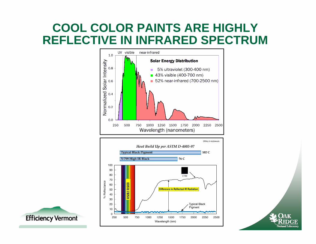
COOL COLOR PAINTS ARE HIGHLY REFLECTIVE IN INFRARED SPECTRUM
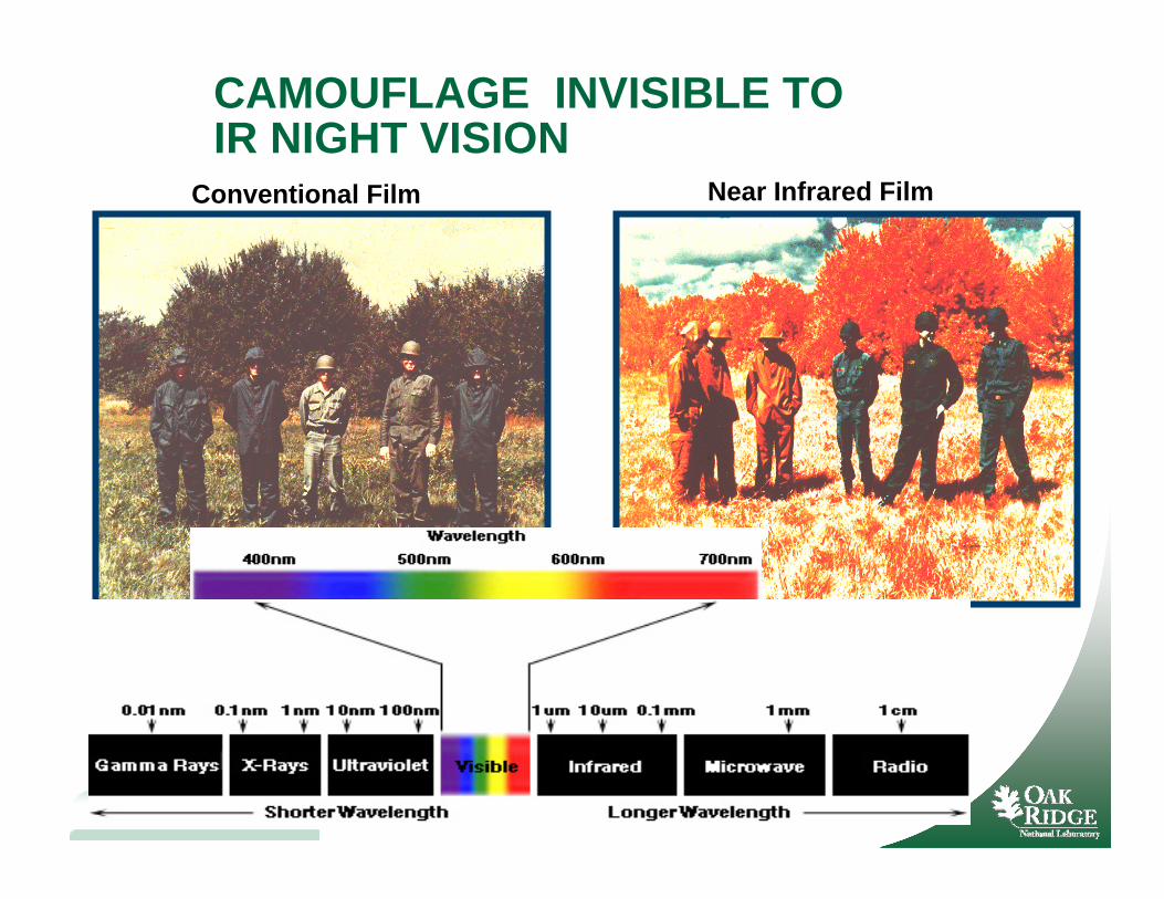
CAMOUFLAGE INVISIBLE TOIR NIGHT VISION
Near Infrared FilmConventional Film
Cool Tile IR CoatingTM Applied to Concrete Tile
COOL TILE IR COATING™ technology was developed by Joe Reilly of American Rooftile Coatings
S-Mission Tile Have Lowest Heat Transfer Penetrating the Roof Deck
1:30 PM
Demonstration Showcasing Painted Metal Shakes at Fair Oaks, CA
House-4 4991 Mariah Place
House-2 4983 Mariah Place
Ultra Cool 31% reflectanceSouth facing roof
Custom-Bilt Painted Metal Shakes and StuccoORNL
Cool Coating Reduces Heat Flux Through South Facing Roof Deck
Painted Metal Roofs
House-1 4979 Mariah Place
House-3 4987 Mariah Place
COOL TILE IR COATING™COOL TILE IR COATING™41% reflective
Finished with Medium-profile Concrete Tile and Stucco
Demonstration Showcasing Hanson Concrete Tile at Fair Oaks, CA
Medium-profile concrete tileSame setup used at Fair Oaks Demonstration
Batten and Counter-Batten
Batten Direct-to-Deck
(ESRA) Envelope Systems Research Apparatus
Medium-profile conventional concrete tile on double batten performs as well as cool-color tile direct-to-deck
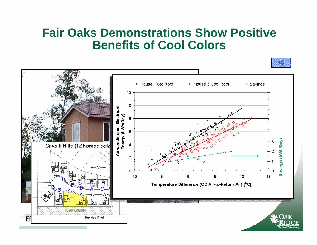
Fair Oaks Demonstrations Show Positive Benefits of Cool Colors
Squares of Roof Products F.W. Dodge Report 2003
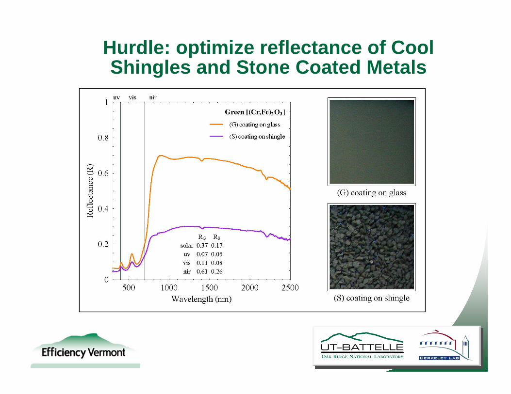
Hurdle: optimize reflectance of Cool Shingles and Stone Coated Metals
Demonstration Homes Provided by Elk Corp and Ochoa & Shehan
Custom Homes
2605 Eel Street, Redding CA 2605 Loggerhead St., Redding CA
SR ~ 0.090 SR ~ 0.255
Heat Flux Penetrating West Roof Reduced 25% of Conventional Shingle
110 Million Existing Homes in U.S. that 110 Million Existing Homes in U.S. that Require Improvements in Building EnvelopeRequire Improvements in Building Envelope
0
20
40
60
80
100
120
140
160
180
0 24 48
Time (hrs)
Tem
pera
ture
(o F)
Tooth Surface
LP TechShield Top
Underside LPTechShieldAir gap
Top Tdeck EPS
Underside of TdeckEPSCenter Cavity
Conventional AtticOutdoor air
Retrofit Shingle Roof
Envelope Systems Research Apparatus
WHAT ABOUT ROOF/ATTIC VENTILATION ?
Develop empirical algorithms to capture energy benefits of above-sheathing ventilation
– Status: heat transfer correlations checked against field data, tracer gas used for airflow measures, algorithm formulated & validated
MCA installing stone-coated metal roofs on ESRA
Clay tile, concrete tile, painted metal shake, asphalt shingle, and stone-coated metal roofs field tests
Formulate and Validate AtticSim for Cool Color and Above-Sheathing Ventilation
ESRA
Attic Assembly Construction andInstrument Setup
ASV Reduced Heat Flow Crossing Deck by 30% of Asphalt Shingle
August 2005
Deck Heat Flow Reduced 45% byIRR pigments and ASV
Above Sheathing Ventilation ~ 30% of control
SR increase of 0.17 ~ 15% of control
)(COSQQQ
QHFT
DeckRoofMassAbsSolarventDeck
HFTfloorAttic
HFTDeckRoof
ventAttic Q)(COS
QQ
Above-sheathing ventilation accelerated the removal of unwanted moisture
2-D MOISTURE-EXPERT model (Karagiozis)
reduced moisture content in OSB well below that of OSB in a non-vented cavity
Regional Criteria for Above-Sheathing Ventilation Develop Recommendations for above-Sheathing Ventilation
and submit for public review and acceptance as standards practice
Maximize attic contribution to energy savings through integration of key strategies into Next Generation Attic
PCM, cool roofs (IRR), above sheathing ventilation and radiant barriers combined into Next Generation Attic
Computer Tool Benchmarking
Next Generation PrototypesNext Generation PrototypesMilestones ( )Milestones ( )
26
MCA Field Testing of Painted MetalESRA
Lane Installation Radiant Barrier Insulation101 Offset from deck 4.0-in, dual air channel Low-e foil on deck facing up Hardy Board (0.5-in)2
11 Offset from deck 0.75-in using clips Backer on metal underside No insulation above deck
12 Direct-to-Deck (option for variable space) Low-e paint on underside No insulation above deck
131Offset from deck 4.0-in, forced ventilation Low-e foil on deck facing up No insulation above deck
14 Offset from deck 0.75-in using clips Backer on metal underside ≈ R-1.0 above deck
15 Offset from deck 0.75-in using clips Low-e paint on underside No insulation above deck
1Roof and attic assemblies already under evaluation.2Hardy board used to separate two air channels above roof deck.
Lane Installation Radiant Barrier Insulation101 Offset from deck 4.0-in, dual air channel Low-e foil on deck facing up Hardy Board (0.5-in)2
11 Offset from deck 4-in using clips Backer on metal underside No insulation above deck
12 Offect from deck 2-in using clips Low-e paint on underside No insulation above deck
131Offset from deck 4.0-in, forced ventilation Low-e foil on deck facing up No insulation above deck
14 Offset from deck 0.75-in using clips Backer on metal underside ≈ R-1.0 above deck
15 Offset from deck 0.75-in using clips Low-e paint on underside No insulation above deck
1Roof and attic assemblies already under evaluation.2Hardy board used to separate two air channels above roof deck.
27
Roof with ¾- and 2-in airspace yield similar roof heat flows to roof with 4-in airspace
Roof with R-1 insulation placed above deck yields similar thermal performance to roof with ¾-in airspace above deck
AtticSIM II (Attic Simulation) Model
k
1st Generation Roof and Attic
Painted metal roof (SR28E81, 4-in air gap, 2 Low-e, PCMs)
Advanced Attic with PCM Shaves Peak Demandand Reduces Night Sky Losses
Peak Demand Reduction
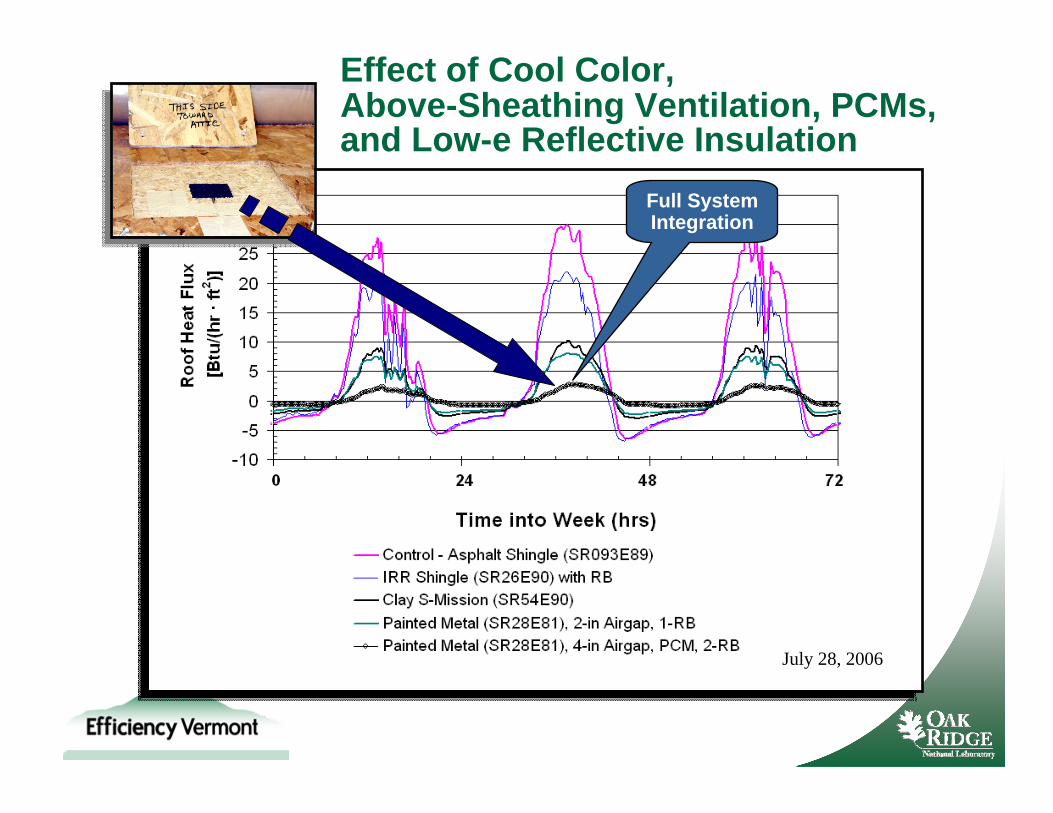
Effect of Cool Color, Above-Sheathing Ventilation, PCMs,and Low-e Reflective Insulation
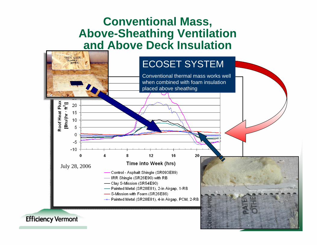
ECOSET SYSTEMConventional thermal mass works well when combined with foam insulation placed above sheathing
Energy Plus Simulation: PCM in Fiberglass Insulation Blown on Attic Floor
About $1.30 per ft2 of attic floor would be spent to increase thermal resistance of conventional blown-in fiberglass insulation
AtticSIM (Attic Simulation) Model
Florida Solar Energy Center
Roof EnergyRoof Energy
BalanceBalance
ASTM C 1340-99 Standard For Estimating Heat Gain of Loss Through Ceilings Under Attics
Miller et al. (2007), “Natural Convection Heat Transfer in Roofs with Above-Sheathing Ventilation.”
Ceiling Heat Flux
AtticSIM II ValidationsAsphalt Shingle (SR093E89)
Asphalt Shingle (SR093E89) with radiant barrier facing attic space
OSB with RB facing attic
Ceiling Heat Flux
AtticSIM II ValidationsFlat Concrete tile (SR13E83) on double batten system
AtticSIM II Validations S-Mission Clay Tile (SR54E90)
Direct-to-Deck
Heat flux through roof deck
S-Mission Clay Tile (SR54E90) with 1¼-in EPS insulation on roof deck (Ecoset)
Heat flux through roof deck
AtticSIM Simulations Include Duct SystemSummer Duct Loss Cools AtticWinter Duct Loss Heats Attic
1
4 7 9
3 6 8
11
2 5 10
12
Return (12 in OD)
Leakage In (4%)
Supply (12 in OD)
Leakage Out (4%)
Leakage Out (4%)
Leakage Out (4%)
Leakage Out (4%)
HVAC
Supply Duct 309 ft2Return Duct 176 ft2
0
100
200
300
400
500
600
700
800
900
1000
0 100 200 300 400 500 600 700 800 900 1000
Measured HVAC Capacity (Btu/hr)
Pred
icte
d D
uct C
apac
ity (B
tu/h
r)
Winter No RBWinter RBSummer No RBSummer RB
AtticSim Duct Validation
0.0
0.2
0.4
0.6
0.8
1.0
1.2
1.4
1.6
1.8
2.0
0.0 0.2 0.4 0.6 0.8 1.0 1.2 1.4 1.6 1.8 2.0
Measured T (oF)
Pred
icte
d
T (o F)
Winter No RBWinter RBSummer No RBSummer RB
Petrie, T.W., Wilkes, K.E. et al. (1998), “Effect of Radiant Barriers and Attic ventilation on Residential Attics and Attic Duct Systems: New tools for Measuring and Modeling.”ASHRAE Transactions, June 1998.
0
2,000
4,000
6,000
8,000
10,000
12,000
14,000
16,000
18,000
20,000
0 10 20 30 40 50 60
Insulation R-Value
Ann
ual C
eilin
g &
Duc
t Loa
d (k
Btu
/yr) No Radiant barrier
Radiant barrier
0
2,000
4,000
6,000
8,000
10,000
12,000
14,000
16,000
18,000
20,000
0 10 20 30 40 50 60
Insulation R-Value
Ann
ual C
eilin
g &
Duc
t Loa
d (k
Btu
/yr) No Radiant barrier
Radiant barrier
Equivalent R-Value of Ceiling Insulation for SR25E75 Roof with Inspected Ducts
Zone 09: Attic Contains R-30 Insulation and AC Ducts with R-6 Insulation
Equivalent R-13
$700 for 1400 ft2 attic footprint by BNI (2008)
Equivalent R-Value of Insulation for SR25E75 Roof with Inspected Ducts
Zone 15: Attic Contains R-38 Insulation and AC Ducts with R-8 Insulation
0
5,000
10,000
15,000
20,000
25,000
30,000
35,000
0 10 20 30 40 50 60
Insulation R-Value
Ann
ual C
eilin
g &
Duc
t Loa
d (k
Btu
/yr) No Radiant barrier
Radiant barrier
0
5,000
10,000
15,000
20,000
25,000
30,000
35,000
0 10 20 30 40 50 60
Insulation R-Value
Ann
ual C
eilin
g &
Duc
t Loa
d (k
Btu
/yr) No Radiant barrier
Radiant barrier
Equivalent R-24
$1200 for 1400 ft2 attic footprint by BNI (2008)
Annual Cost of Ceiling and Duct Energy based on TDV 30-yr forecast of $0.145 per kBtu NG
$0
$100
$200
$300
$400
$500
$600
0 10 20 30 40 50 60
Insulation R-Value
Pres
ent V
alue
$ p
er y
ear Annual Savings $47
$0
$100
$200
$300
$400
$500
$600
0 10 20 30 40 50 60
Insulation R-Value
Pres
ent V
alue
$ p
er y
ear Annual Savings $47
Zone 15: Attic Contains R-38 Insulation and AC Ducts with R-8 Insulation