IJSRSET162180 | Received: 19 January 2016 | Accepted : 10 February 2016 | January-February 2016 [(2)1: 621-634]
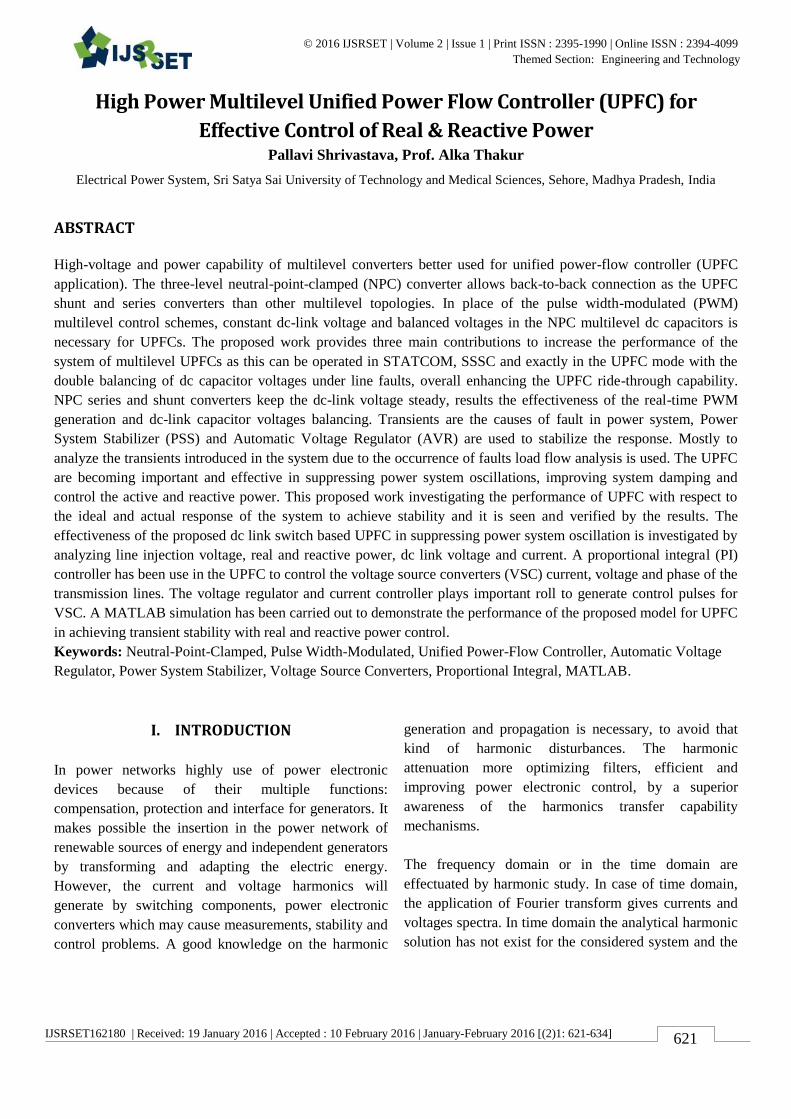
© 2016 IJSRSET | Volume 2 | Issue 1 | Print ISSN : 2395-1990 | Online ISSN : 2394-4099 Themed Section: Engineering and Technology
621
High Power Multilevel Unified Power Flow Controller (UPFC) for
Effective Control of Real & Reactive Power Pallavi Shrivastava, Prof. Alka Thakur
Electrical Power System, Sri Satya Sai University of Technology and Medical Sciences, Sehore, Madhya Pradesh, India
ABSTRACT
High-voltage and power capability of multilevel converters better used for unified power-flow controller (UPFC
application). The three-level neutral-point-clamped (NPC) converter allows back-to-back connection as the UPFC
shunt and series converters than other multilevel topologies. In place of the pulse width-modulated (PWM)
multilevel control schemes, constant dc-link voltage and balanced voltages in the NPC multilevel dc capacitors is
necessary for UPFCs. The proposed work provides three main contributions to increase the performance of the
system of multilevel UPFCs as this can be operated in STATCOM, SSSC and exactly in the UPFC mode with the
double balancing of dc capacitor voltages under line faults, overall enhancing the UPFC ride-through capability.
NPC series and shunt converters keep the dc-link voltage steady, results the effectiveness of the real-time PWM
generation and dc-link capacitor voltages balancing. Transients are the causes of fault in power system, Power
System Stabilizer (PSS) and Automatic Voltage Regulator (AVR) are used to stabilize the response. Mostly to
analyze the transients introduced in the system due to the occurrence of faults load flow analysis is used. The UPFC
are becoming important and effective in suppressing power system oscillations, improving system damping and
control the active and reactive power. This proposed work investigating the performance of UPFC with respect to
the ideal and actual response of the system to achieve stability and it is seen and verified by the results. The
effectiveness of the proposed dc link switch based UPFC in suppressing power system oscillation is investigated by
analyzing line injection voltage, real and reactive power, dc link voltage and current. A proportional integral (PI)
controller has been use in the UPFC to control the voltage source converters (VSC) current, voltage and phase of the
transmission lines. The voltage regulator and current controller plays important roll to generate control pulses for
VSC. A MATLAB simulation has been carried out to demonstrate the performance of the proposed model for UPFC
in achieving transient stability with real and reactive power control.
Keywords: Neutral-Point-Clamped, Pulse Width-Modulated, Unified Power-Flow Controller, Automatic Voltage
Regulator, Power System Stabilizer, Voltage Source Converters, Proportional Integral, MATLAB.
I. INTRODUCTION
In power networks highly use of power electronic
devices because of their multiple functions:
compensation, protection and interface for generators. It
makes possible the insertion in the power network of
renewable sources of energy and independent generators
by transforming and adapting the electric energy.
However, the current and voltage harmonics will
generate by switching components, power electronic
converters which may cause measurements, stability and
control problems. A good knowledge on the harmonic
generation and propagation is necessary, to avoid that
kind of harmonic disturbances. The harmonic
attenuation more optimizing filters, efficient and
improving power electronic control, by a superior
awareness of the harmonics transfer capability
mechanisms.
The frequency domain or in the time domain are
effectuated by harmonic study. In case of time domain,
the application of Fourier transform gives currents and
voltages spectra. In time domain the analytical harmonic
solution has not exist for the considered system and the
International Journal of Scientific Research in Science, Engineering and Technology (ijsrset.com)
622
relations between harmonics cannot be simplified. In
case of frequency domain, there are many ways to find
out power network harmonic analysis exist [1]. The
simple way to calculate the sources of harmonic current
is exist by power electronic devices. Norton equivalent
is another way to calculate the harmonic analysis. These
two methods are mostly used to calculate the network
harmonic analysis. These two technique are simple but
not accurate, because of not exist dynamics of the
switching components.
More accurate models to design for power electronic
devices. In this transfer functions model, matrix
equations are linked with converter state variables.
Another method [2] Newton‟s method is solved the
converter which is set of nonlinear equations. This
model has a high accuracy, but due to more complex
they cannot be used in systems containing multiple
converters. When we reduce harmonics induced by the
switching process is required to express accurate
network harmonic analysis, easy and capable method. In
frequency domain, the periodicity of the converter
variables in steady state put in matrix form. In [3], the
power electronic structures are built having harmonic
transfer matrices and implemented by Matlab/Simulink.
This method is mostly used for stability analysis and
because of these data simplified and high frequencies are
neglected. In [4], periodicity method of variables is
presented, but this gives only numerical solution and it is
not applied in network analysis and switching circuits.
The analytical expressions are not fit for harmonics
expressions.
With the development of technology, the power system
utilities around the world changes rapidly with
improvements in power system structures and operation.
With the expansion of technology, system will be more
optimal and profitable operation in power system
regarding generation, transmission and distribution
system [1].
The main aim of FACTS Technology is follows:
To enhance the power flow capability in
transmission network.
To provide direct control over designated
transmission routes.
To enhance thermal limits of the transmission
line.
To improve the damping of oscillations and line
capacity [5].
FACTS technology is a collection of controllers that are
situated separately or coordination with other devices to
control one or more interconnected power system such
as shunt impedance, series impedance, current, voltage
and damping oscillations. This concept is known as
FACTS Controllers [5].
1.1 Background
In 1980‟s the Electric Power Research Institute (EPRI)
gives a theory of improve the stability and reliability in
power systems. This technology is named as Flexible
Alternating Current Transmission Systems technology.
By the using of FACTS Technology it is ability to
increase and control as well as to improve the
transmission system with the stability of power flow,
stability limits in power systems [3, 4] In 1980s, a
different type of FACTS controller techniques
introduced as per demand of the power systems [5].
In 1990s introduced designed based on the concept of
combined series-shunt FACTS Controller having the. It
capability of improve the power flow control with
stability and reliability and also. The ability to
simultaneously control all the transmission parameters
without affecting the power flow of transmission line i.e.
voltage, line impedance and phase angle, this is known
as Unified Power Flow Controller (UPFC) [2].
1.2 Problem Formation
Now a day, in developing countries large number of
interconnected networks, the generation reserves to
increase the reliability of the power system. However,
fluctuations in reliability of power supply increase with
interconnection complex system, it is very difficult to
control the power flow and security problems due to
large number of blackouts in world. And the reason is
fault sequences because of systematical errors in the
arrangement as well as operation, feeble interconnection
lack of maintenance or overload in the network [2].
To reduce these consequences and to provide better
power flow along with line which makes system stability
and reliability required to new transmission lines
installations. But new installation is limited for some
factor like environment related issues, economic cost.
International Journal of Scientific Research in Science, Engineering and Technology (ijsrset.com)
623
This complex installing is new challenges the power
engineer to increase the power flow with transmission
line power system challenges the power engineers to
increase the power flow with transmission line without
implementation in the system stability with security.
1.3 Aim of the project
Goal of the project in this thesis is the using of Unified
Power Flow Controller (UPFC). We take a case study
network of power system, with the help of Newton-
Raphson Algorithm and the simulations of the algorithm
finding out the power flow equation derived for network
solution in MATLAB.
The active and reactive-power as well as voltage
magnitude control simultaneously of their fast control
characteristics is regulated by FACTS controllers and it
has also capability to continuous compensating and
maintain voltages level for desired value and also the
FACTS controller the ability to improve both transient
and small signal stability margins. Without generation
topological or rearrangement change in the network
Control the power flows, under normal and abnormal
conditions, and also reduce power loss and improve
stability and performance. [1]. It is necessary to find out
the optimal location for installed the devices to improve
voltage stability margins and increase network security
[2-7]. According to proper control objective, Reliability
and loadability has been studied [5-15]. Some papers are
tried to find the location for install Flexible Alternating
Current Transmission Systems to enhance power system
laudability and security [14-17]. In deregulated power
systems has been presented in optimal allocation of
these devices [18-19].
In This thesis we enhance the voltage study level
considering investment cost and power losses by optimal
location of multi-type FACTS devices.
Many genetic algorithms are optimization problems like,
and, congestion management, controller optimization,
economic dispatch and optimal power flow etc in power
systems [21-22].
II. METHODS AND MATERIAL
1. Flexible Alternating Current Transmission
Systems (Facts)
According to definition of IEEE, “The Flexible
Alternating Current Transmission System (FACTS) is
new technology based on power electronic devices
which offers an prospect to increase power transfer
capability, controllability and stability of Alternating
Current Transmission Systems” [7].
To enhance the growth of industrial area, it is required to
provide a stable, secure, controlled and economic quality
in highly complex system. To achieve for better quality
of power, it is compulsory to increase the transmitted by
installing new transmission lines or by improving
previous lines by adding new controlling devices.
Installation a new transmission lines is not possible
because of few reason like economic condition, cost and
time taken. Therefore power engineers have to
determined and examine to installed control devices in
existing transmission system. After they come up the
new concept to installed the new control devices in
existing transmission line, which is flexible in
nature.[12].
In1980s Electric Power Research Institute (EPRI) was
introduced the concept of Flexible AC Transmission
Systems (FACTS) technology, which enhance the
security, flexibility and capacity of transmission systems.
In this new concept which is based on power electronic
switching device and dynamic controllers to increase the
capacity of power transfer and system utilization and
also power quality, security, stability and reliability in
AC transmission system. This technology of FACTS is
known as FACTS controller.
1.1 Model based on facts devices Generation of FACTS Controllers:
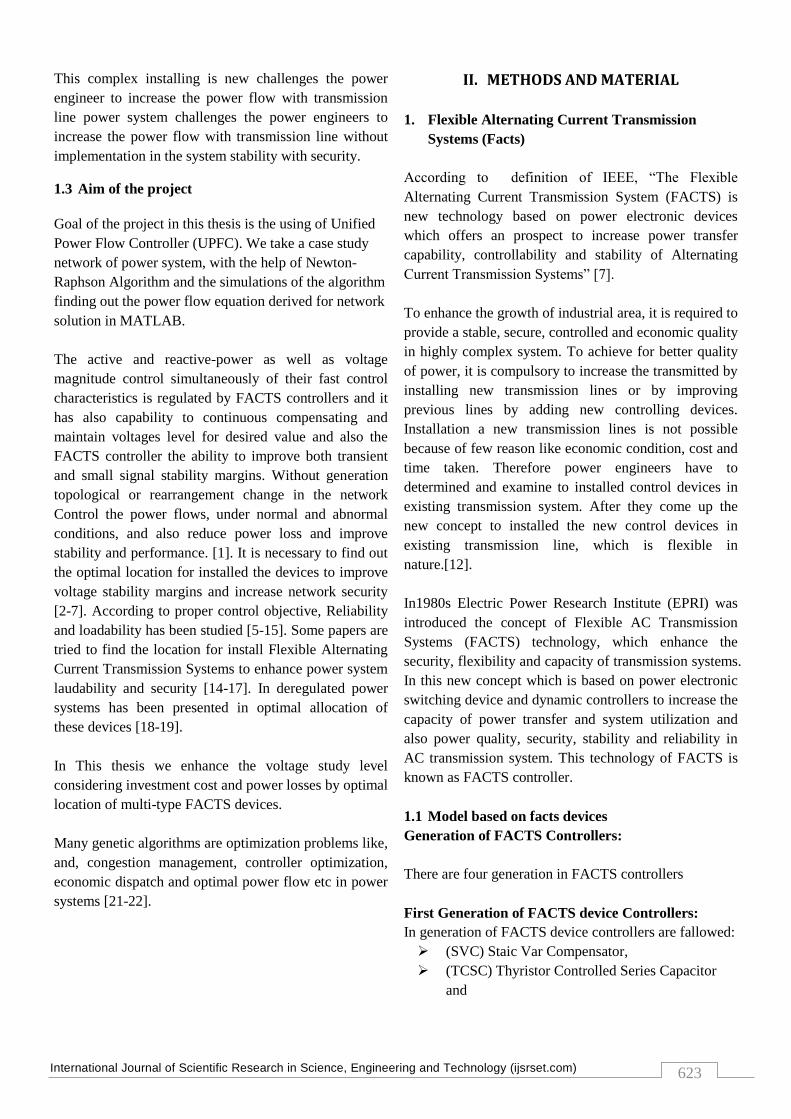
There are four generation in FACTS controllers
First Generation of FACTS device Controllers:
In generation of FACTS device controllers are fallowed:
(SVC) Staic Var Compensator,
(TCSC) Thyristor Controlled Series Capacitor
and
International Journal of Scientific Research in Science, Engineering and Technology (ijsrset.com)
624
(TCPST) Thyristor Controlled Phase Shifting
Transformer.
In this work, we have selected three different FACTS
devices, location to improve voltage stability margins in
power system,
SSSC (Static Synchronous Series Compensator),
SVC (Static VAR Compensator),
UPFC (Unified Power Flow Controller).
In transmission line the power flow namely i - j is
depend in line reactance, magnitudes voltage and phase
angle in between sending buses and receiving buses.
This expression by Eq. 1
In transmission line TCSC control line reactance and
SVC can control reactive power in line. But UPFC
control all power flow parameters like phase angle, bus
voltage, line impedance. So utilization in power system
by optimal choice and allocation of FACTS devices is
obtained. These controllers designed are based on the
concept of FACTS technology, which increases the
reliability, stability and power flow control is known as
FACTS controllers. This controller was developed to
overcome the problems occurring in power system. But
some controllers having the capacity overcome the
multiple problems in a power system and some
controller are limited to solve a particular problem. All
these controllers are the family of FACTS controllers
and these are follows:
First Generation of FACTS Controllers:
Static Var Compensator (SVC),
Thyristor Control Series Compensator (TCSC).
Second Generation of FACTS Controllers:
Static Synchronous Series Compensator (SSSC),
Static Synchronous Compensator (STATCOM).
Third Generation of FACTS Controllers:
Unified Power Flow Controller (UPFC)
Interline Power Flow Controller (IPFC) and
Fourth Generation of FACTS Controllers:
Generalized Power Flow Controller (GUPFC)
Figure 1. Block Diagram of FACTS Controllers
2. Different types of FACTS Controllers:
2.1 First Generation of FACTS Controllers:
In first generation of FACTS controllers is based on
thyristor technology.
Static Var Compensator (SVC):
This is the first device of FACTS controller, it provide
fast-acting reactive power compensation in transmission
system.
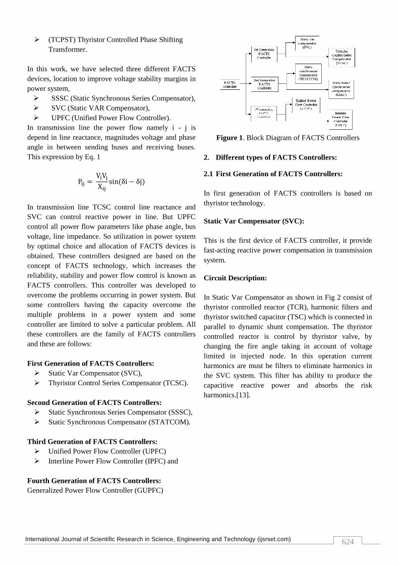
Circuit Description:
In Static Var Compensator as shown in Fig 2 consist of
thyristor controlled reactor (TCR), harmonic filters and
thyristor switched capacitor (TSC) which is connected in
parallel to dynamic shunt compensation. The thyristor
controlled reactor is control by thyristor valve, by
changing the fire angle taking in account of voltage
limited in injected node. In this operation current
harmonics are must be filters to eliminate harmonics in
the SVC system. This filter has ability to produce the
capacitive reactive power and absorbs the risk
harmonics.[13].
International Journal of Scientific Research in Science, Engineering and Technology (ijsrset.com)
625
Figure 1. Circuit Diagram of Static Var Compensator
[12]
Chracteristics of SVC:
The SVC provide, improve of power flow control,
increase the damping power oscillations and also
provide a dynamic voltage control to increase the
transient stability in power transmission system.
The SVC is mostly control the reactive power, reduced
the voltage level due to non-linear level, improves the
power factor, power quality and reduces the energy
consumption. [14].
Advantages:
To maintain bus voltage near to constant level.
To improve transient stability.
It is mostly used in electrified railway, wind power
generation and metallurgy etc. [14].
Thyristor Controlled Series Compensator (TCSC):
The TCSC is thyristor control based FACTS technology
having ability to control the line impedance which is
installed series with thyristor-controlled capacitor in
transmission line. In TCSC a series capacitor installed to
reduce the total series impedance to enhance the
transmission line capability thus additional power will
be transferred [7].
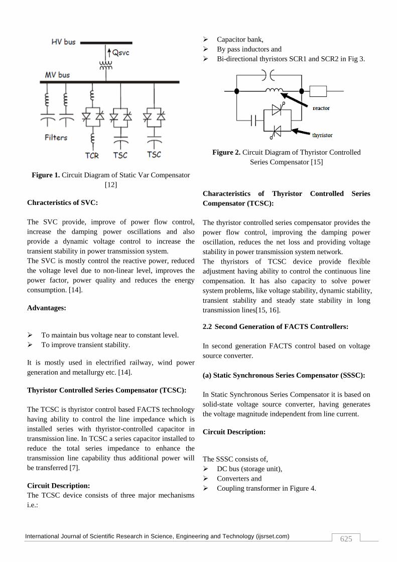
Circuit Description:
The TCSC device consists of three major mechanisms
i.e.:
Capacitor bank,
By pass inductors and
Bi-directional thyristors SCR1 and SCR2 in Fig 3.
Figure 2. Circuit Diagram of Thyristor Controlled
Series Compensator [15]
Characteristics of Thyristor Controlled Series
Compensator (TCSC):
The thyristor controlled series compensator provides the
power flow control, improving the damping power
oscillation, reduces the net loss and providing voltage
stability in power transmission system network.
The thyristors of TCSC device provide flexible
adjustment having ability to control the continuous line
compensation. It has also capacity to solve power
system problems, like voltage stability, dynamic stability,
transient stability and steady state stability in long
transmission lines[15, 16].
2.2 Second Generation of FACTS Controllers:
In second generation FACTS control based on voltage
source converter.
(a) Static Synchronous Series Compensator (SSSC):
In Static Synchronous Series Compensator it is based on
solid-state voltage source converter, having generates
the voltage magnitude independent from line current.
Circuit Description:
The SSSC consists of,
DC bus (storage unit),
Converters and
Coupling transformer in Figure 4.
International Journal of Scientific Research in Science, Engineering and Technology (ijsrset.com)
626
In SSSC the dc bus used to the inverter synthesize AC
voltage waveform which is injected series with
transmission line through transformer having proper
phase angle and line current. If the injected voltage is in
phase with line current it changes a real power and this
voltage in quadrature with line current it changes
reactive power. However, it is ability to change both real
and reactive power in a transmission line [17, 18].
Figure 3. Block Diagram of Static Synchronous Series
Compensator (SSSC) [18]
Characteristics of Static Synchronous Series
Compensator SSSC:
The SSSC generate considerable voltage independent
from line current magnitude, by modulating reactive line
impedance and combining both real and reactive power
compensation to provide high damping of oscillation.
To compensate both reactive and resistive voltage drop
is the capability to change both active and reactive
power, however it maintain a high effective X/R ration
independent from degree of series oscillation.
The SSSC of the FACTS device is improve the power
flow control, damping of power oscillations and
transient stability [19].
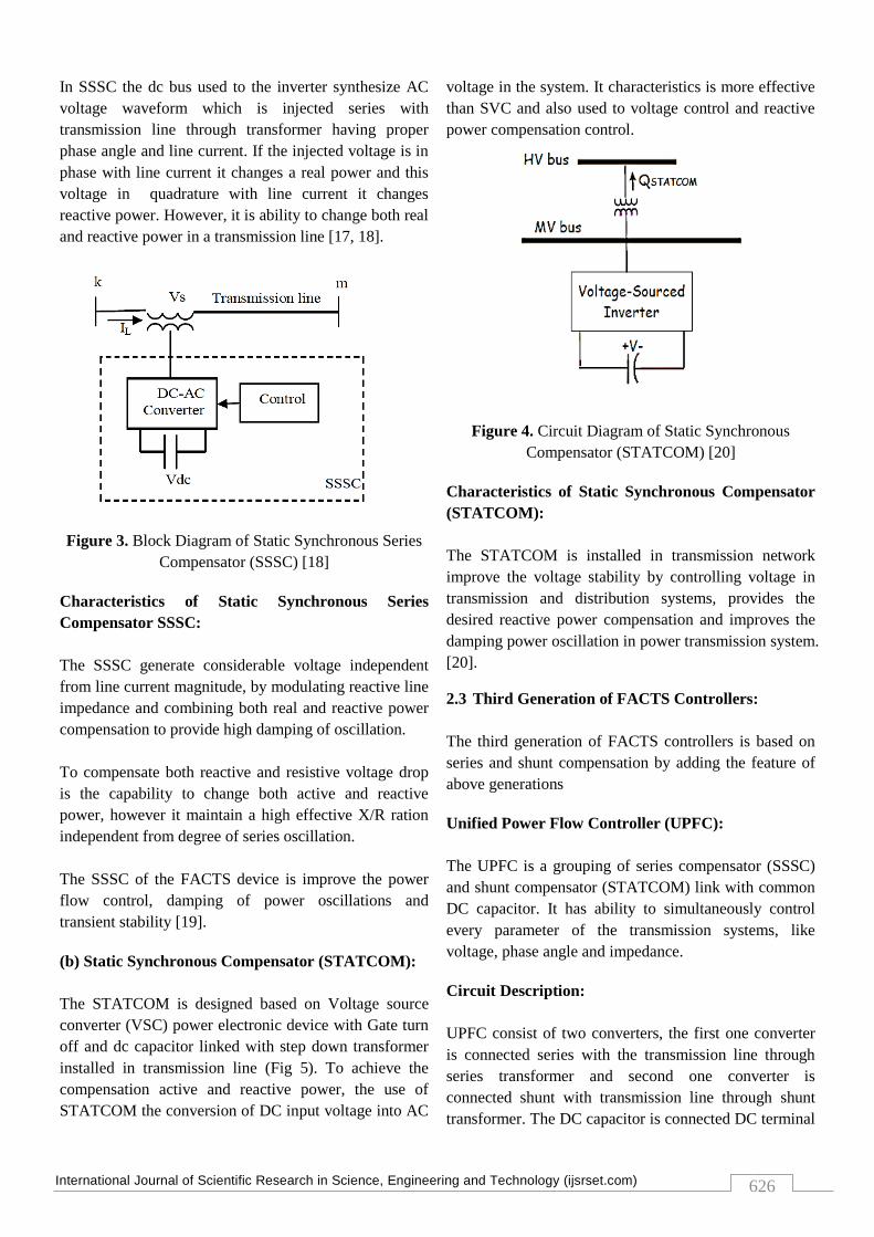
(b) Static Synchronous Compensator (STATCOM):
The STATCOM is designed based on Voltage source
converter (VSC) power electronic device with Gate turn
off and dc capacitor linked with step down transformer
installed in transmission line (Fig 5). To achieve the
compensation active and reactive power, the use of
STATCOM the conversion of DC input voltage into AC
voltage in the system. It characteristics is more effective
than SVC and also used to voltage control and reactive
power compensation control.
Figure 4. Circuit Diagram of Static Synchronous
Compensator (STATCOM) [20]
Characteristics of Static Synchronous Compensator
(STATCOM):
The STATCOM is installed in transmission network
improve the voltage stability by controlling voltage in
transmission and distribution systems, provides the
desired reactive power compensation and improves the
damping power oscillation in power transmission system.
[20].
2.3 Third Generation of FACTS Controllers:
The third generation of FACTS controllers is based on
series and shunt compensation by adding the feature of
above generations
Unified Power Flow Controller (UPFC):
The UPFC is a grouping of series compensator (SSSC)
and shunt compensator (STATCOM) link with common
DC capacitor. It has ability to simultaneously control
every parameter of the transmission systems, like
voltage, phase angle and impedance.
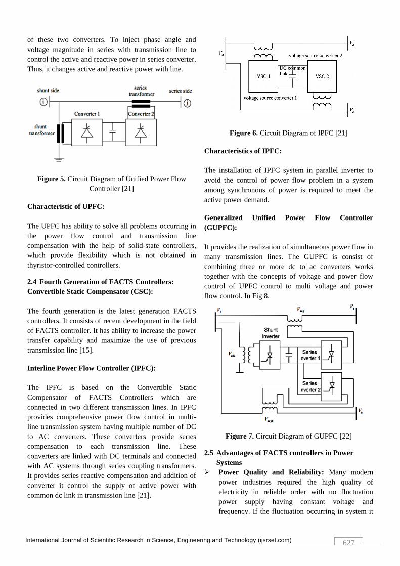
Circuit Description:
UPFC consist of two converters, the first one converter
is connected series with the transmission line through
series transformer and second one converter is
connected shunt with transmission line through shunt
transformer. The DC capacitor is connected DC terminal
International Journal of Scientific Research in Science, Engineering and Technology (ijsrset.com)
627
of these two converters. To inject phase angle and
voltage magnitude in series with transmission line to
control the active and reactive power in series converter.
Thus, it changes active and reactive power with line.
Figure 5. Circuit Diagram of Unified Power Flow
Controller [21]
Characteristic of UPFC:
The UPFC has ability to solve all problems occurring in
the power flow control and transmission line
compensation with the help of solid-state controllers,
which provide flexibility which is not obtained in
thyristor-controlled controllers.
2.4 Fourth Generation of FACTS Controllers:
Convertible Static Compensator (CSC):
The fourth generation is the latest generation FACTS
controllers. It consists of recent development in the field
of FACTS controller. It has ability to increase the power
transfer capability and maximize the use of previous
transmission line [15].
Interline Power Flow Controller (IPFC):
The IPFC is based on the Convertible Static
Compensator of FACTS Controllers which are
connected in two different transmission lines. In IPFC
provides comprehensive power flow control in multi-
line transmission system having multiple number of DC
to AC converters. These converters provide series
compensation to each transmission line. These
converters are linked with DC terminals and connected
with AC systems through series coupling transformers.
It provides series reactive compensation and addition of
converter it control the supply of active power with
common dc link in transmission line [21].
Figure 6. Circuit Diagram of IPFC [21]
Characteristics of IPFC:
The installation of IPFC system in parallel inverter to
avoid the control of power flow problem in a system
among synchronous of power is required to meet the
active power demand.
Generalized Unified Power Flow Controller
(GUPFC):
It provides the realization of simultaneous power flow in
many transmission lines. The GUPFC is consist of
combining three or more dc to ac converters works
together with the concepts of voltage and power flow
control of UPFC control to multi voltage and power
flow control. In Fig 8.
Figure 7. Circuit Diagram of GUPFC [22]
2.5 Advantages of FACTS controllers in Power
Systems
Power Quality and Reliability: Many modern
power industries required the high quality of
electricity in reliable order with no fluctuation
power supply having constant voltage and
frequency. If the fluctuation occurring in system it
International Journal of Scientific Research in Science, Engineering and Technology (ijsrset.com)
628
effected in the quality of power voltage drops,
frequency variations and loss that lead to
interruptions in transmission system. Installation of
TCSC having the ability to overcome this limitation
in transmission system which increases the
reliability for the consumer.
Power system stability: In the transmission system
due to long transmission lines, interconnected
system, changing system loads and line fault occurs.
Instabilities in power system. It results reduced
transmission power. By the using of FACTS
devices increase transfer capacity and reduced
tripping in transmission line.
Flexibility: By the using FACTS devices controller
the transmission lines has flexible in nature with
existing line requires only 12 to 18 months
Environmental Benefits: By installing the new
transmission line is unconstructive impact on the
economical and ecological factors. however, by the
using of FACTS devices modify in existing
transmission lines makes the system more
economical.
Reduced maintenance cost: Maintenance cost in
FACTS controllers are fewer as compared to the
installation new transmission lines by the increase of
number of transmission line. The probability of fault
occurring is more. But with the help of FACTS devices
converter minimize the faults in transmission line. This
is reducing the maintenance cost.
3. Power Flow Control In Power System
In a transmission line the power flow depends three
important parameters namely,
Voltage magnitude (V),
Line Impedance ( Z) and
Phase angle between buses (θ).
By using placement and co-ordination of several flexible
ac transmission systems controllers in large scale power
system networks and also small signal stability, transient
stability, damping oscillations, increase load ability of
power system network dynamic performance of the
power system, capability of power transfer through the
line, efficiency of power system, quality of the power
system, congestion management, voltage profile, less
active power loss, power system security in FACTS
devices control. In FACTS device the response is quick
and correct. Therefore these devices improve the voltage
profile with the help of coordinated control of FACTS
controllers in multi-machine systems.
In this chapter power flow studies is developed from
steady state model of FACTS devices TCSC is simply to
modify the reactance of transmission line. But SVC and
UPFC using the power injection models [14-16]. TCSC,
UPFC and SVC is modeled is bus as shunt element in
integrated into transmission line. By using MATLAB
programming language the Mathematical models for
FACTS devices are implemented.
TCSC:
In transmission line the capacitive or inductive
compensator are modify reactance by TCSC. We know
that TCSC is modeled line reactance in transmission as
below:
Xij= Xline+ XTCSC
XTCSC = rTCRC .Xline
Where Xline is reactance of transmission line and TCSC
is compensation factor. TCSC reactance is chosen
between -0.7 Xline to 0.2 Xline.
SVC:
SVC can be. In this paper SVC is modeled as an ideal
injection of reactive power in bus and also it is used for
both inductive and capacitive compensation:
∆Qi = ∆QSVC (4)
UPFC:
In this paper the UPFC models is represented by two
types. First one is coupled model and second is
decoupled model. In first type of UPFC model (coupled
model) is modeled with series combination of voltage
source and impedance in transmission line. In second
type of UPFC model (decoupled model) it can be
modeled into two separated buses. First one is more
complex compared with the second one because of
modification of Jacobian matrix in coupled model is
inevitable.
In conventional algorithms power flow without
modification of Jacobian matrix elements can be easily
implemented in decoupled model, in this paper, but here
decoupled model is used for modeling UPFC in power
flow study (Fig. 9).
International Journal of Scientific Research in Science, Engineering and Technology (ijsrset.com)
629
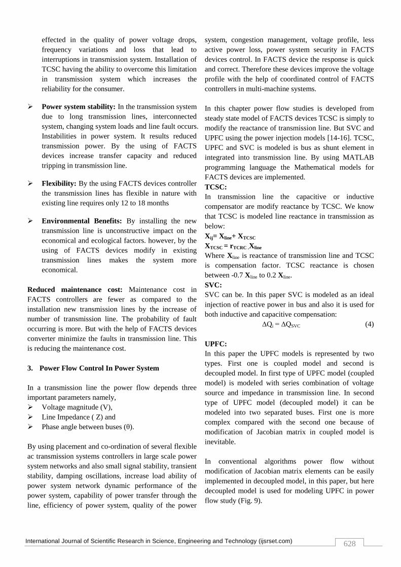
Figure 9. Decoupled model for UPFC
UPFC controls power flow is installed in the
transmission line. To express the UPFC model in load
flow analysis, it has four variables: Pu1, Qu1, Pu2, and
Qu2. And it is lossless, real power flow from bus i to bus
j can be written as:
Pij = Pu1
However, the UPFC cannot generate the real power, but
control the power flow. So:
Pu1 + Pu2 = 0
The output of the reactive power of UPFC, Qu1 Qu2 is
set of arbitrary value to maintain bus voltage.
4. Mathematical Modelling
4.1 The Unified Power Flow Controller
In 1991 Gyugiy was introduced the Unified Power Flow
Controller. The UPFC is a member of third generation
FACTS controller proposed to control voltage and
power flow in systems It consist of combining features
of Series Synchronous Compensator (SSSC) and Static
Synchronous Compensator (STATCOM). It has to
ability to control active and reactive power in
transmission line as well as transmission parameters like
voltage, impedance and phase angle.
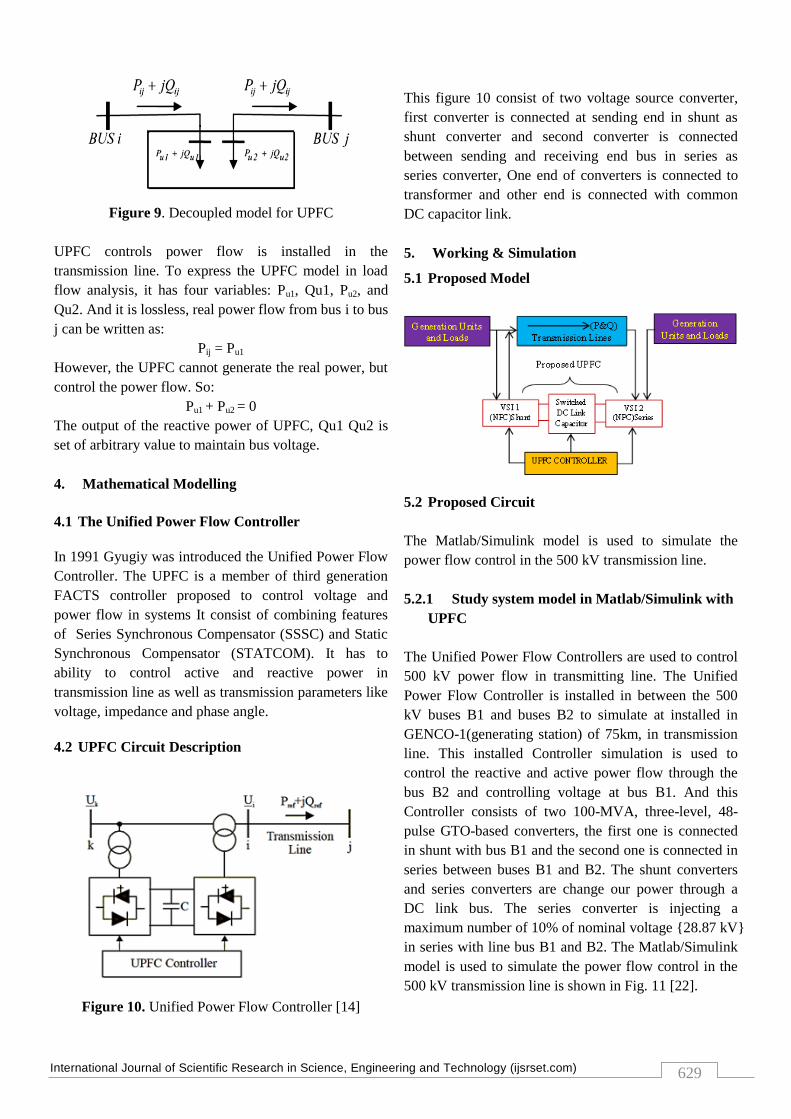
4.2 UPFC Circuit Description
Figure 10. Unified Power Flow Controller [14]
This figure 10 consist of two voltage source converter,
first converter is connected at sending end in shunt as
shunt converter and second converter is connected
between sending and receiving end bus in series as
series converter, One end of converters is connected to
transformer and other end is connected with common
DC capacitor link.
5. Working & Simulation
5.1 Proposed Model
5.2 Proposed Circuit
The Matlab/Simulink model is used to simulate the
power flow control in the 500 kV transmission line.
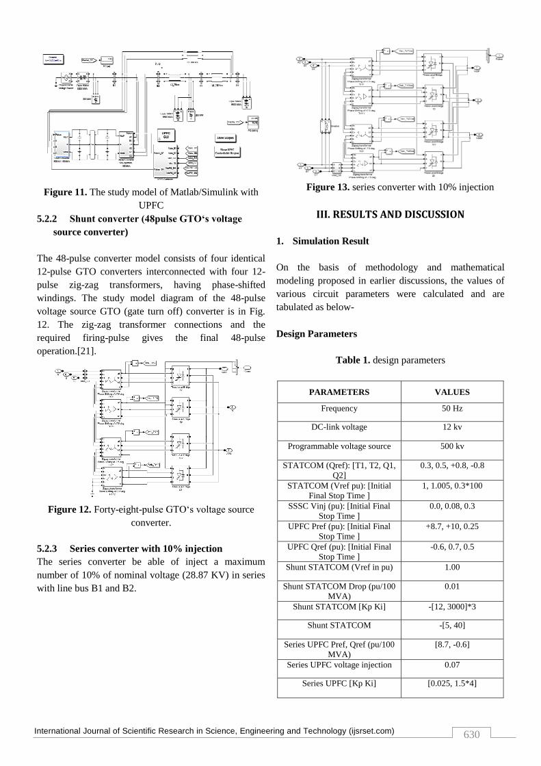
5.2.1 Study system model in Matlab/Simulink with
UPFC
The Unified Power Flow Controllers are used to control
500 kV power flow in transmitting line. The Unified
Power Flow Controller is installed in between the 500
kV buses B1 and buses B2 to simulate at installed in
GENCO-1(generating station) of 75km, in transmission
line. This installed Controller simulation is used to
control the reactive and active power flow through the
bus B2 and controlling voltage at bus B1. And this
Controller consists of two 100-MVA, three-level, 48-
pulse GTO-based converters, the first one is connected
in shunt with bus B1 and the second one is connected in
series between buses B1 and B2. The shunt converters
and series converters are change our power through a
DC link bus. The series converter is injecting a
maximum number of 10% of nominal voltage {28.87 kV}
in series with line bus B1 and B2. The Matlab/Simulink
model is used to simulate the power flow control in the
500 kV transmission line is shown in Fig. 11 [22].
International Journal of Scientific Research in Science, Engineering and Technology (ijsrset.com)
630
Figure 11. The study model of Matlab/Simulink with
UPFC
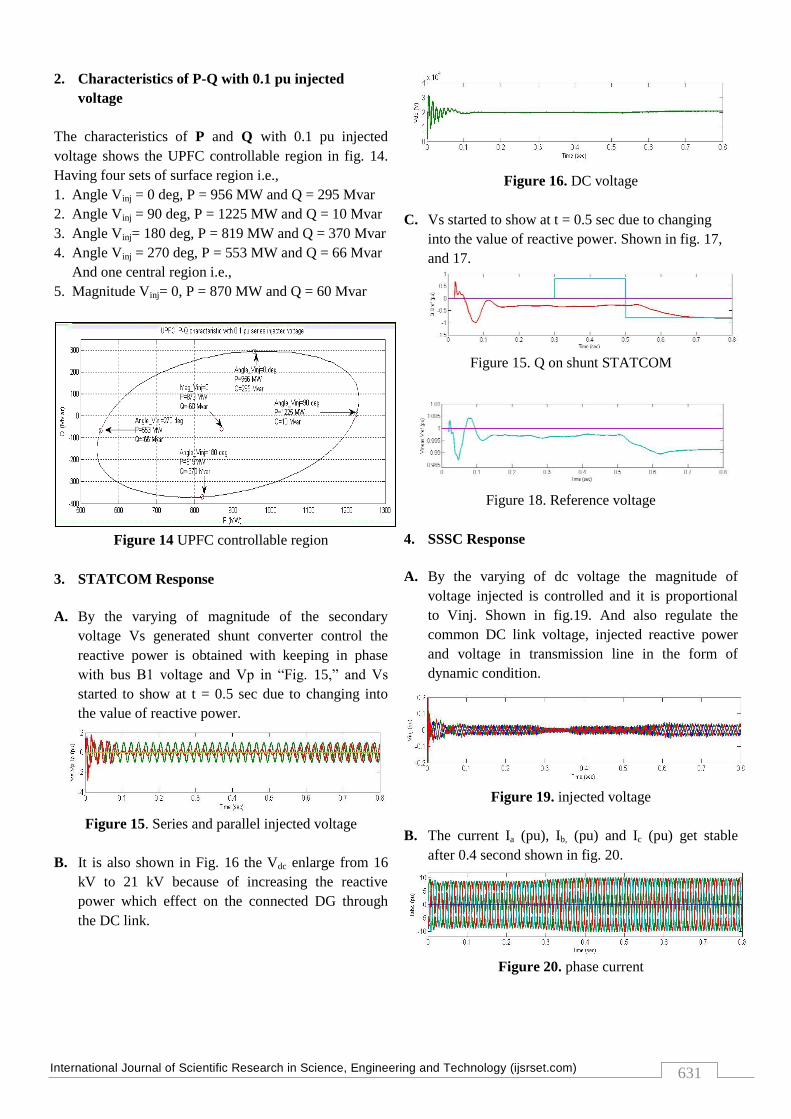
5.2.2 Shunt converter (48pulse GTO‘s voltage
source converter)
The 48-pulse converter model consists of four identical
12-pulse GTO converters interconnected with four 12-
pulse zig-zag transformers, having phase-shifted
windings. The study model diagram of the 48-pulse
voltage source GTO (gate turn off) converter is in Fig.
12. The zig-zag transformer connections and the
required firing-pulse gives the final 48-pulse
operation.[21].
Figure 12. Forty-eight-pulse GTO„s voltage source
converter.
5.2.3 Series converter with 10% injection
The series converter be able of inject a maximum
number of 10% of nominal voltage (28.87 KV) in series
with line bus B1 and B2.
Figure 13. series converter with 10% injection
III. RESULTS AND DISCUSSION
1. Simulation Result
On the basis of methodology and mathematical
modeling proposed in earlier discussions, the values of
various circuit parameters were calculated and are
tabulated as below-
Design Parameters
Table 1. design parameters
PARAMETERS VALUES
Frequency 50 Hz
DC-link voltage 12 kv
Programmable voltage source 500 kv
STATCOM (Qref): [T1, T2, Q1,
Q2]
0.3, 0.5, +0.8, -0.8
STATCOM (Vref pu): [Initial
Final Stop Time ]
1, 1.005, 0.3*100
SSSC Vinj (pu): [Initial Final
Stop Time ]
0.0, 0.08, 0.3
UPFC Pref (pu): [Initial Final
Stop Time ]
+8.7, +10, 0.25
UPFC Qref (pu): [Initial Final
Stop Time ]
-0.6, 0.7, 0.5
Shunt STATCOM (Vref in pu) 1.00
Shunt STATCOM Drop (pu/100
MVA)
0.01
Shunt STATCOM [Kp Ki] -[12, 3000]*3
Shunt STATCOM -[5, 40]
Series UPFC Pref, Qref (pu/100
MVA)
[8.7, -0.6]
Series UPFC voltage injection 0.07
Series UPFC [Kp Ki] [0.025, 1.5*4]
International Journal of Scientific Research in Science, Engineering and Technology (ijsrset.com)
631
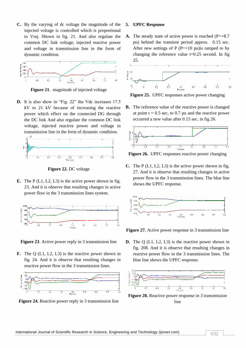
2. Characteristics of P-Q with 0.1 pu injected
voltage
The characteristics of P and Q with 0.1 pu injected
voltage shows the UPFC controllable region in fig. 14.
Having four sets of surface region i.e.,
1. Angle Vinj = 0 deg, P = 956 MW and Q = 295 Mvar
2. Angle Vinj = 90 deg, P = 1225 MW and Q = 10 Mvar
3. Angle Vinj= 180 deg, P = 819 MW and Q = 370 Mvar
4. Angle Vinj = 270 deg, P = 553 MW and Q = 66 Mvar
And one central region i.e.,
5. Magnitude Vinj= 0, P = 870 MW and Q = 60 Mvar
Figure 14 UPFC controllable region
3. STATCOM Response
A. By the varying of magnitude of the secondary
voltage Vs generated shunt converter control the
reactive power is obtained with keeping in phase
with bus B1 voltage and Vp in “Fig. 15,” and Vs
started to show at t = 0.5 sec due to changing into
the value of reactive power.
Figure 15. Series and parallel injected voltage
B. It is also shown in Fig. 16 the Vdc enlarge from 16
kV to 21 kV because of increasing the reactive
power which effect on the connected DG through
the DC link.
Figure 16. DC voltage
C. Vs started to show at t = 0.5 sec due to changing
into the value of reactive power. Shown in fig. 17,
and 17.
Figure 15. Q on shunt STATCOM
Figure 18. Reference voltage
4. SSSC Response
A. By the varying of dc voltage the magnitude of
voltage injected is controlled and it is proportional
to Vinj. Shown in fig.19. And also regulate the
common DC link voltage, injected reactive power
and voltage in transmission line in the form of
dynamic condition.
Figure 19. injected voltage
B. The current Ia (pu), Ib, (pu) and Ic (pu) get stable
after 0.4 second shown in fig. 20.
Figure 20. phase current
International Journal of Scientific Research in Science, Engineering and Technology (ijsrset.com)
632
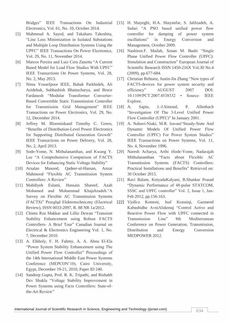
C. By the varying of dc voltage the magnitude of the
injected voltage is controlled which is proportional
to Vinj. Shown in fig. 21. And also regulate the
common DC link voltage, injected reactive power
and voltage in transmission line in the form of
dynamic condition.
Figure 21. magnitude of injected voltage
D. It is also show in “Fig. 22” the Vdc increases 17.5
kV to 21 kV because of increasing the reactive
power which effect on the connected DG through
the DC link And also regulate the common DC link
voltage, injected reactive power and voltage in
transmission line in the form of dynamic condition.
Figure 22. DC voltage
E. The P (L1, L2, L3) is the active power shown in fig.
23. And it is observe that resulting changes in active
power flow in the 3 transmission lines system.
Figure 23. Active power reply in 3 transmission line
F. The Q (L1, L2, L3) is the reactive power shown in
fig. 24. And it is observe that resulting changes in
reactive power flow in the 3 transmission lines.
Figure 24. Reactive power reply in 3 transmission line
5. UPFC Response
A. The steady state of active power is reached (P=+8.7
pu) behind the transient period approx. 0.15 sec.
After new settings of P (P=+10 pu)is ramped to by
changing the reference value t=0.25 second. In fig
25.
Figure 25. UPFC responses active power changing
B. The reference value of the reactive power is changed
at point t = 0.5 sec, to 0.7 pu and the reactive power
occurred a new value after 0.15 sec. in fig 26.
Figure 26. UPFC responses reactive power changing
C. The P (L1, L2, L3) is the active power shown in fig.
27. And it is observe that resulting changes in active
power flow in the 3 transmission lines. The blue line
shows the UPFC response.
Figure 27. Active power response in 3 transmission line
D. The Q (L1, L2, L3) is the reactive power shown in
fig. 208. And it is observe that resulting changes in
reactive power flow in the 3 transmission lines. The
blue line shows the UPFC response.
Figure 28. Reactive power response in 3 transmission
line
International Journal of Scientific Research in Science, Engineering and Technology (ijsrset.com)
633
6. FFT analysis
FFT analysis for the voltage in the Bus B1 after
stabilization. We can see that the harmonics is reduced
up to 1.04 %
Figure 29-1 FFT analysis
7. Comparing results of UPFC response
Table 2 result analysis
PARAMETERS REFERENCES
RESULT
PROPOSED
RESULT
Active power T = 4 sec, P =
+10 (pu)
T = 3.8 sec, P
= +10 (pu)
Reactive power T = 6.5 sec, Q =
+0.7 (pu)
T = 6.2 sec, Q
= +0.7 (pu)
Harmonics
distortion
1.2 % 1.04 %
Injected voltage T = 0.62 sec, Vinj
= 0.03 (pu)
T = 0.6 sec,
Vinj = 0.03
(pu)
DC link capacitor
voltage
T = 0.5 sec, Vdc
= 2*10^4 (pu)
T = 0.09 sec,
Vdc = 2*10^4
(pu)
IV. CONCLUSION AND FUTURE SCOPE
The stability of power system using FACTS devices like
UPFC is compared and discussed, with the major
disturbance the dynamics of the system is compared
with the presence of STATCOM & UPFC in the system.
Improvement in stability is compared by the reference
work which has been before now done, by using the
STATCOM. The simulation results show that significant
enhancement in the system performance by the use of
UPFC as system stabilization and the harmonics in the
line voltage.The proposed high power multilevel UPFC
control strategy includes dc-link voltage control gains
with low sensitivity to dc link current and the balancing
of the dc-link capacitor voltages using both multilevel
converters.
The dc-link capacitor voltages are balanced using both
series and shunt multilevel converters in spite of only
one of the multilevel converters. The main improvement
is to reduce the harmonics by .16% of the line voltage
and stabilisation of the system. This gives the
effectiveness of the proposed work to operate in three
different modes as per the requirement compared to the
works which have been already implemented.
The proposed thought is modelled and designed in
MATLAB Simulink and the results verify the
effectiveness of the model. Transients and THD are the
major cause in the power system related to power
quality issues. This is useful to in the high power
transmission lines for the stabilisation of the system and
also to maintain the line voltage as per the demand with
good power quality aspects. Here as the dc-link
capacitor is introduced between two converters known
as series and shunt converters maintain the level of it.
V. REFERENCES
[1] Saman Babaei, Bruce Fardanesh, and Subhashish
Bhattacharya, “High-Power VSC-Based
Simultaneous Positive and Negative-Sequence
Voltage Regulator” IEEE Transactions on Power
Delivery, Vol. 29, No. 5, October 2014.
[2] Sajjad Golshannavaz, Farrokh Aminifar, and
Daryoush Nazarpour “Application of UPFC to
Enhancing Oscillatory Response of Series-
Compensated Wind Farm Integrations” IEEE
Transactions On Smart Grid, Vol. 5, No. 4, July
2014.
[3] Natália M. R. Santos, J. Fernando Silva, Jan
Verveckken, Vitor M. Fernão Pires, and Rui
Castro “Enhancing the Ride-Through Capability
of DC-Link Voltage in NPC Multilevel Unified
Power-Flow Controllers” IEEE Transactions On
Power Delivery, Vol. 29, No. 4, August 2014.
[4] AitorLaka, Jon Andoni Barrena, Javier Chivite-
Zabalza, Miguel Ángel Rodríguez Vidal, and
Pedro Izurza-Moreno “Voltage Source Converter
Topology for High-Power Applications
Serializing Three-Phase Converters and H-
0 0.02 0.04 0.06 0.08 0.1 0.12 0.14 0.16 0.18-1
0
1
FFT window: 10 of 40 cycles of selected signal
Time (s)
0 200 400 600 800 10000
0.05
0.1
0.15
0.2
0.25
0.3
0.35
0.4
Frequency (Hz)
Fundamental (50Hz) = 0.9995 , THD= 1.04%
Mag (
% o
f F
undam
enta
l)
International Journal of Scientific Research in Science, Engineering and Technology (ijsrset.com)
634
Bridges” IEEE Transactions On Industrial
Electronics, Vol. 61, No. 10, October 2014.
[5] Mahmoud A. Sayed, and Takaharu Takeshita,
“Line Loss Minimization in Isolated Substations
and Multiple Loop Distribution Systems Using the
UPFC” IEEE Transactions On Power Electronics,
Vol. 29, No. 11, November 2014.
[6] Marcos Pereira and Luiz Cera Zanetta “A Current
Based Model for Load Flow Studies With UPFC”
IEEE Transactions On Power Systems, Vol. 28,
No. 2, May 2013.
[7] Nima Yousefpoor IEEE, Babak Parkhideh, Ali
Azidehak, Subhashish Bhattacharya, and Bruce
Fardanesh “Modular Transformer Converter-
Based Convertible Static Transmission Controller
for Transmission Grid Management” IEEE
Transactions on Power Electronics, Vol. 29, No.
12, December 2014.
[8] Jeffrey M. Bloeminkand Timothy C. Green,
“Benefits of Distribution-Level Power Electronics
for Supporting Distributed Generation Growth”
IEEE Transactions on Power Delivery, Vol. 28,
No. 2, April 2013.
[9] Sode-Yome, N. Mithulananthan, and Kwang Y.
Lee “A Comprehensive Comparison of FACTS
Devices for Enhancing Static Voltage Stability”
[10] Arsalan Masood, Qadeer-ul-Hassan, Anzar
Mahmood “Flexible AC Transmission System
Controllers: A Review”
[11] Mahdiyeh Eslami, Hussain Shareef, Azah
Mohamed and Mohammad Khajehzadeh.“A
Survey on Flexible AC Transmission Systems
(FACTS)” Przegląd Elektrotechniczny (Electrical
Review), ISSN 0033-2097, R. 88 NR 1a/2012.
[12] Chintu Rza Makkar and Lillie Dewan “Transient
Stability Enhancement using Robust FACTS
Controllers- A Brief Tour” Canadian Journal on
Electrical & Electronics Engineering Vol. 1, No.
7, December 2010.
[13] A. Elkholy, F. H. Fahmy, A. A. Abou El-Ela
“Power System Stability Enhancement using The
Unified Power Flow Controller” Proceedings of
the 14th International Middle East Power Systems
Conference (MEPCON‟10), Cairo University,
Egypt, December 19-21, 2010, Paper ID 240.
[14] Sandeep Gupta, Prof. R. K. Tripathi, and Rishabh
Dev Shukla “Voltage Stability Improvement in
Power Systems using Facts Controllers: State-of-
the-Art Review”
[15] H. Shayeghi, H.A. Shayanfar, S. Jalilzadeh, A.
Safari “A PSO based unified power flow
controller for damping of power system
oscillations” in Energy Conversion and
Management, October 2009.
[16] Nashiren.F. Mailah, Senan M. Bashi “Single
Phase Unified Power Flow Controller (UPFC):
Simulation and Construction” European Journal of
Scientific Research ISSN 1450-216X Vol.30 No.4
(2009), pp.677-684.
[17] Christian Rehtanz, Justin-Jin Zhang “New types of
FACTS-devices for power system security and
efficiency” AUGUST 2007 DOI:
10.1109/PCT.2007.4538332 • Source: IEEE
Explore.
[18] A. Sapin, J.-J.Simond, P. Allenbach
“Investigation Of The 3-Level Unified Power
Flow Controller (UPFC)” In January 2001.
[19] A. Nabavi-Niaki, M.R. lravani“Steady-State And
Dynamic Models Of Unified Power Flow
Controller (UPFC) For Power System Studies”
IEEE Transactions on Power Systems, Vol. 11,
No. 4, November 1996.
[20] Naresh Acharya, Arthi tSode-Yome, Nadarajah
Mithulananthan “Facts about Flexible AC
Transmission Systems (FACTS) Controllers:
Practical Installations and Benefits” Retrieved on:
30 October 2015.
[21] Ravi Balam, KotyadaKalyani, B.Shankar Prasad
“Dynamic Performance of 48-pulse STATCOM,
SSSC and UPFC controller” Vol. 2, Issue 1, Jan-
Feb 2012, pp.156-163.
[22] Vjollca Komoni, Isuf Krasniqi, Gazmend
Kabashidhe AvniAlidemaj “Control Active and
Reactive Power Flow with UPFC connected in
Transmission Line” 8th Mediterranean
Conference on Power Generation, Transmission,
Distribution and Energy Conversion
MEDPOWER 2012.