High precision /High resolution pressure switch. Applicable for pressure detection with a wide range of fluids, by using a stainless steel diaphragm. High Precision, Digital Pressure Switch For General Fluids Series ZSE F/ISE 50 60 50 60 16-2-25 ZSEISEPSE Z I SE3 PS Z I SE 1 2 ZSP ISA2 ISZSM PF2IFData
Transcript
High precision/High resolution pressure switch.Applicable for pressure detection with a wide range
of fluids, by using a stainless steel diaphragm.
High Precision,Digital Pressure Switch For General Fluids
Series ZSE F/ISE5060
5060
16-2-25
ZSEISE
PSEZI SE3
PSZI SE1
2
ZSP
ISA2
IS
ZSM
PF2
IF
Data
Pressure sensor
Fitting
Stainless steel diaphragm
Pressure detection for a wide range of fluids.
Hydraulic fluid (JIS-K2213)
Silicon oil (JIS-K2213)
Lubricating oil (JIS-K6301)
Fluoro carbon
Enclosure
Panel mount
Panel mount + Front side protection cover
With bracket
To confirm adsorption of workpieces containing water
To confirm primary pressure of cleaning line
To confirm working pressure of hydraulic cylinderApplication
examples
Option
Using of stainless steel diaphragm
Extremely low leakage
To confirm absorption of workpiece with water on the surface, e.g. wet LCD glass plate
To measure hydraulic pressure
The stainless steel diaphragm prevents direct contact between sensor and measured fluid.
Argon
Air containing drain
Ammonia
Freon
Carbon dioxideNitrogen
Liquid and gas contact areas Stainless steel 630Fittings Stainless steel 304
Sensor and fittings are electron-beam welded.Leakage is kept at the lowest level by using VCR
and Swedgelok fittings.ZSE50F / ISE50 1 x 10⁻⁵ Pa⋅m3/sZSE60F / ISE60 1 x 10⁻¹⁰ Pa⋅m3/s
IP65
To measure low-quality air, containing drain
Leakage test with nitrogen
16-2-26
High precision and high resolution
Compound pressure
Repeatability 0.2% F.S. 1 digit or less
Variety of functions
Variations
Anti-chattering function
Auto shift function
Auto preset function
• Key lock function
• Peak and bottom display function
• Zero out function
Automatic pressure setting is possible.Saves time for setting operation.
Special fitting types are used in semiconductor production equipment (Metal gasket seal fittings)
Selectable response times: 2.5 ms (default), 24 ms,192 ms, 768 ms or less
ModelStandard thread type Special fittings for the semiconductor industry
(Metal gasket seal fittings)
Port size
Rated pressure range
OutputSwitch output
Analog output
Leak rate 1 x 10⁻⁵ Pa. m3/ s
ZSE50F ISE50 ZSE60F ISE60
2 outputs NPN or PNP
100 kPa
–100 kPa
0
1MPa
0
100 kPa
–100 kPa
0
1 MPa
0
1 x 10⁻¹⁰ Pa ⋅m3/s
Output voltage 1 to 5 V
R 1/ 4 , NPT 1/4 , G 1/ 4 (With M5 male thread) URJ 1 /4 , TSJ 1 / 4
Prevents erroneous operation due to sudden fluctuations in primary pressure, by allowing the response time to be changed.
Pressure detection is not affected by fluctuations in primary pressure.
16-2-27
ZSEISE
PSEZI SE3
PSZI SE1
2
ZSP
ISA2
IS
ZSM
PF2
IF
Data
Analog Output
Suitable model: ZSE50F/ISE50--22/62(L)-(M)
Series ISE50
1.0 MPa0
Pressure
1
5
Ana
log
outp
ut v
alue
(V)
Pressure
Series ZSE50F
100 kPa
1
5
100 kPa
Ana
log
outp
ut v
alue
(V)
How to Order
ZSE50 02
ISE50 02
22
22
For compound pressure
For positive pressure
Unit specification
OptionNil
A
None
Bracket A
D
E
Panel mount
F
Panel mount + Front protection cover
Option
∗ Option
When option parts are required separately, use the following part numbers to place an order.
MF
M
L
L
Nil
MWith unit switching function
Fixed SI unit
Lead wire length3 mL
Piping specificationsR 1/4 (M5 with female screw), Piping in backward direction
NPT 1/4 (M5 with female screw), Piping in backward direction
G 1/4 (M5 with female screw), Piping in backward direction
02T2G2∗
Input/Output specificationsNPN open collector 2 output + Analog output
NPN open collector 2 output + Auto shift input
PNP open collector 2 output + Analog output
PNP open collector 2 output + Auto shift input
223062∗
70∗
Option
Bracket A
Bracket D
Panel mount
Panel mount + Front protection cover
Part no.
ZS-24-A
ZS-24-D
ZS-24-E
ZS-24-F
Qty.
1
1
1
1
Note
With 2 pcs. of mounting screws
With 2 pcs. of mounting screws
Note 1) Under the New Measurement Law, which has been in effect since October, 1999, sales of switches with the unit conversion function have not been allowed for use in Japan.
∗ OptionNote) Auto shift input is used for the auto shift function.
For more information, please refer to “Auto Shift Function” on page 16-2-32.
Note 1)
Note 2)
Bracket D
Refer to the dimensions for the difference between brackets A and D.
High Precision,Digital Pressure Switch For General Fluids
Series ZSE50F/ISE50
16-2-28
Possible set range
–100.0 to 100.0 kPa
–1.000 to 1.000 MPa
Regulating pressure range
–100.0 to 100.0 kPa
–0.1 to 1.000 MPa
Specifications
Note)The possible set ranges for types with auto shift function are as follows:
Fluid that will not corrode stainless steel 630 and 30412 to 24 VDC, Ripple (p-p) 10% or less
55 mA or less (With no load)NPN or PNP 2 output (Max. applied voltage 30 V (NPN), Max. load current 80 mA)
Variable (0 or above)Fix (3 digits)
2.5 ms or less (With anti-chattering function: 24 ms, 192 ms, 768 ms or less)Yes
3 1/2 digit LED display (Sampling frequency: 5 times/sec)2% F.S. 1 digit or less (With ambient temperature of 25 3C)
Green LED (OUT1: Light up when ON), Red LED (OUT2: Lights up when ON)
No-voltage input (Solid state switch or reed switch), input 5 ms or moreIP65
Operating: 0 to 50C, Stored: 10 to 60C (No condensation or freezing)Operating and stored: 35 to 85% RH (No condensation)
250 VAC for 1 min, between all lead wires and enclosure 2 MΩ or more (at 50 VDC) between all lead wires and enclosure
10 to 500 Hz with 1.5 mm amplitude or 98 m/s2, whichever is smaller980 m/s2 in X, Y, Z directions 3 times each (Not energized)
3% F.S. or less of measured pressure at 25C in temperature range of 0 to 50CPressure receiving area: Stainless steel 630, Fittings: Stainless steel 304
02: R 1/4, M5 x 0.8 T2: NPT 1/4, M5 x 0.85-wire oil proof heavy-duty cable (0.15 mm2)Approx. 120 g (Each including 3 m lead wire)
0.2% F.S. 1 digit or less 0.3% F.S. 1 digit or less
Output voltage: 1 to 5 V 5% F.S. or less Output voltage: 1 to 5 V 2.5% F.S. or less
Rated pressure rangeOperating pressure range and regulating pressure rangeProof pressure kPa
MPakgf/cm2
barpsi
mmHginHg
Hysteresis mode Window comparator mode
EnclosureAmbient temperature rangeAmbient humidity rangeWithstand voltageInsulation resistanceVibration resistanceShock resistance
ZSE50F (Compound pressure)100 to 100 kPa100 to 100 kPa
500 kPa0.1—
0.0010.0010.02
10.1
ISE50 (Positive pressure)0.000 to 1.000 MPa
0.100 to 1.000 MPa1.5 MPa
—0.0010.010.010.1——
Note 1) In case of types with unit conversion function. (Types without unit conversion function are fixed to the SI units (KPa or MPa).)
Note 2) When a type with analog output is selected.Note 3) When a type with auto shift is selected.Note 4) 0.03 to 0.04 psi in psi display.Note 5) Value clear 0.01 psi in psi display.
Function
Various additional functions are available for easy measurement, switch operation and check of measured values suitable for the conditions of the measured fluid.
Auto shift function Anti-chattering functionKey lock functionPeak hold functionBottom hold functionZero out functionUnit conversion (for overseas use)
Can correct the pressure set point value of switch output according to fluctuations in the primary pressure.Prevents malfunction due to sudden fluctuations in the primary pressure by adjusting the response time.The key board operation can be locked to prevent incorrect operation on the operation switch.Can retain the maximum pressure value displayed during measurement.Can retain the minimum pressure value displayed during measurement.The pressure display can be set at zero when the pressure is open to the atmosphere.Can convert the display value (for overseas use only).
16-2-32
16-2-43
Note 1) Select and order by specifying the types and models.
Response timeOutput short circuit protectionDisplayDisplay accuracyIndicator lightAnalog output Auto shift input
16-2-29
ZSEISE
PSEZI SE3
PSZI SE1
2
ZSP
ISA2
IS
ZSM
PF2
IF
Data
Series ZSE50F/ISE50High Precision,
Digital Pressure Switch for General Fluids
YES
NO
YES
NO
[P]
[n]
OUT1Outputmode
P_1P_2
P_2
n_1n_2
n_1 n_2
HH
HH
H (Fix hysteresis) = 3 digits
H (Fix hysteresis) = 3 digits
∗ Same with OUT2.
OFF
ON
OFF
ON
OFF
ON
OFF
ON
• Hysteresis mode
• Window comparatormode
• Hysteresis mode
• Window comparatormode
P_1
Large pressure and vacuum pressure
Large pressure and vacuum pressure
Large pressure and vacuum pressure
Large pressure and vacuum pressure
Output Method
16-2-30
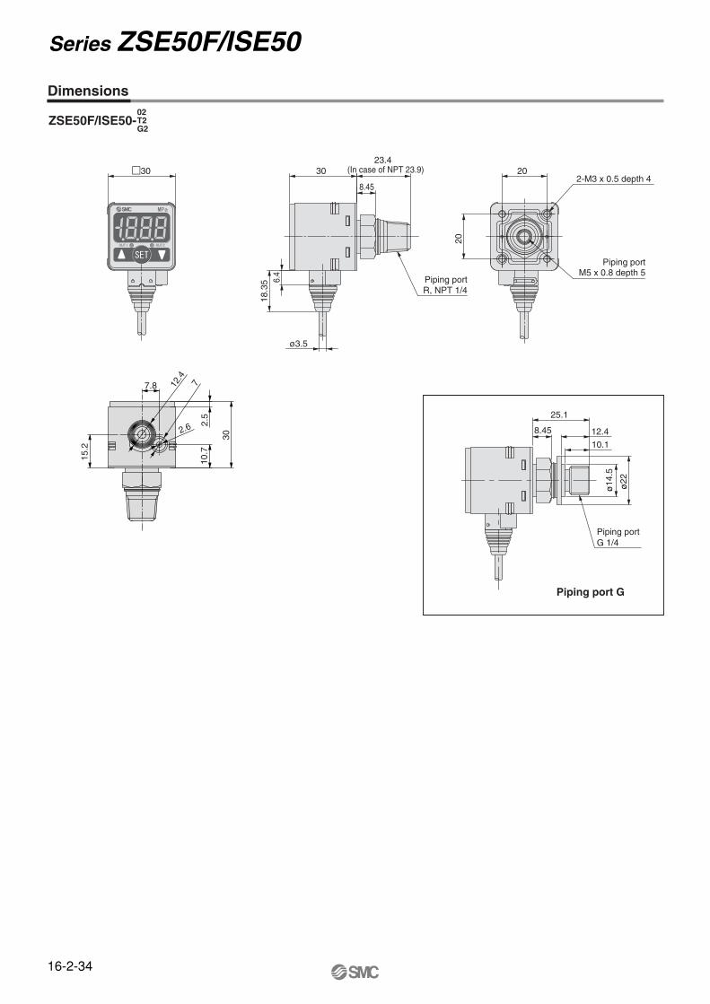
Series ZSE50F/ISE50
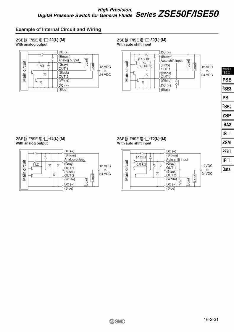
ZSE F/ISE --22(L)-(M)5060
5060 ZSE F/ISE --30(L)-(M)50
605060
ZSE F/ISE --62(L)-(M)5060
5060 ZSE F/ISE --70(L)-(M)50
605060
With analog output With auto shift input
With analog output With auto shift input
Example of Internal Circuit and Wiring
(Brown)DC (+)
(Blue)DC ()
(Black)OUT 1
(White)OUT 2
(Gray)Analog output
1 kΩ 12 VDCto
24 VDC
12 VDCto
24 VDC
12VDCto
24VDC
12 VDCto
24 VDC
Mai
n ci
rcui
tM
ain
circ
uit
Mai
n ci
rcui
tM
ain
circ
uit
LoadLo
ad
6.8 kΩ
1.2 kΩ(Brown)DC (+)
(Blue)DC ()
(Black)OUT 1
(White)OUT 2
(Gray)Auto shift input
LoadLo
ad
1 kΩ
(Brown)DC (+)
(Blue)DC ()
(Black)OUT 1
(White)OUT 2
(Gray)Analog output
Load
Load
6.8 kΩ
1.2 kΩ (Brown)DC (+)
(Blue)DC ()
(Black)OUT 1
(White)OUT 2
(Gray)Auto shift input
Load
Load
16-2-31
ZSEISE
PSEZI SE3
PSZI SE1
2
ZSP
ISA2
IS
ZSM
PF2
IF
Data
Series ZSE50F/ISE50High Precision,
Digital Pressure Switch for General Fluids
Auto Shift Function
Anti-chattering Function
This function uses the measured pressure at the time of auto shift input as the reference pressure value and corrects the set point values “P_1” and “P_2” of switch output 1 and “P_3” and “P_4” of switch output 2. “P_1” to “P_4” correspond to “n_1” to “n_4” in case of normally closed circuit.
When auto shift is not used:Fluctuations in the primary pressure interrupt correct judgement.
Auto shift function conditions and explanation• Keep the pressure constant at least for 5 ms after the last
transition signal of auto shift input.• At the time of auto shift input, the display unit displays “ooo” for
about 1 second. The pressure value at this time is saved as the correction value “C_5” .
• The set point values “P_1” to “P_4” or “n_1” to “n_4” are corrected based on the saved correction values.
• The time between the auto shift input and start of switch output is 10 ms or less.
• If the set point value corrected by auto shift input falls out of the possible set range, the correction value is not saved. The display will show “UUU” if the set point value is above the upper limit and “LLL” if it is below the lower limit.
• The correction value “C_5” set by auto shift input disappears when the power is turned off.
• The correction value “C_5” for the auto shift function is reset to zero (the initial value) when the power is turned on again.
∗ The correction value is not stored on the EEPROM.When auto shift is used:When the primary pressure changes, set the auto shift function to Lo. The pressure value at this point will be saved as the reference value to correct the pressure set point values in order to make correct judgments. Regulating pressure range
–100.0 to 100.0 kPa–0.1 to 1.000 MPa
The possible set range for types with auto shift function
–100.0 to 100.0 kPa–1.000 to 1.000 MPa
Time
Time
ONOFF
Switch output 1, 2
Hi
LoAuto shift input
5 msor more
10 msor less
Switch output response time when auto shift inputs.
P1P2
P1P2
Switch output 1, 2ON
OFF
Normalprimary pressure
Drop ofprimary pressure
Increase ofprimary pressure
Normalprimary pressure
Drop ofprimary pressure
Increase ofprimary pressure
[ ]
Pre
ssur
e
Pre
ssur
e
The possible set range for types with auto shift function is as follows:
A large bore cylinder or ejector consumes a large amount of air in operation and may experience a temporary drop in the primary pressure. This function prevents detection of such temporary drops in primary pressure as abnormal pressure.
<Principle>This function averages pressure values measured during the response time set by the user and then compares the average pressure value with the pressure set point value to output the result on the switch.
Pressure Temporary fluctuation
t (ms) t (ms) Time
Time
Time
<Averaging process> <Averaging process>
Set point value
Switch output operation in
normal conditions
ON
OFF
Switch output operation when
chattering prevention function is on
ON
OFF
P1P2
16-2-32
Series ZSE50F/ISE50
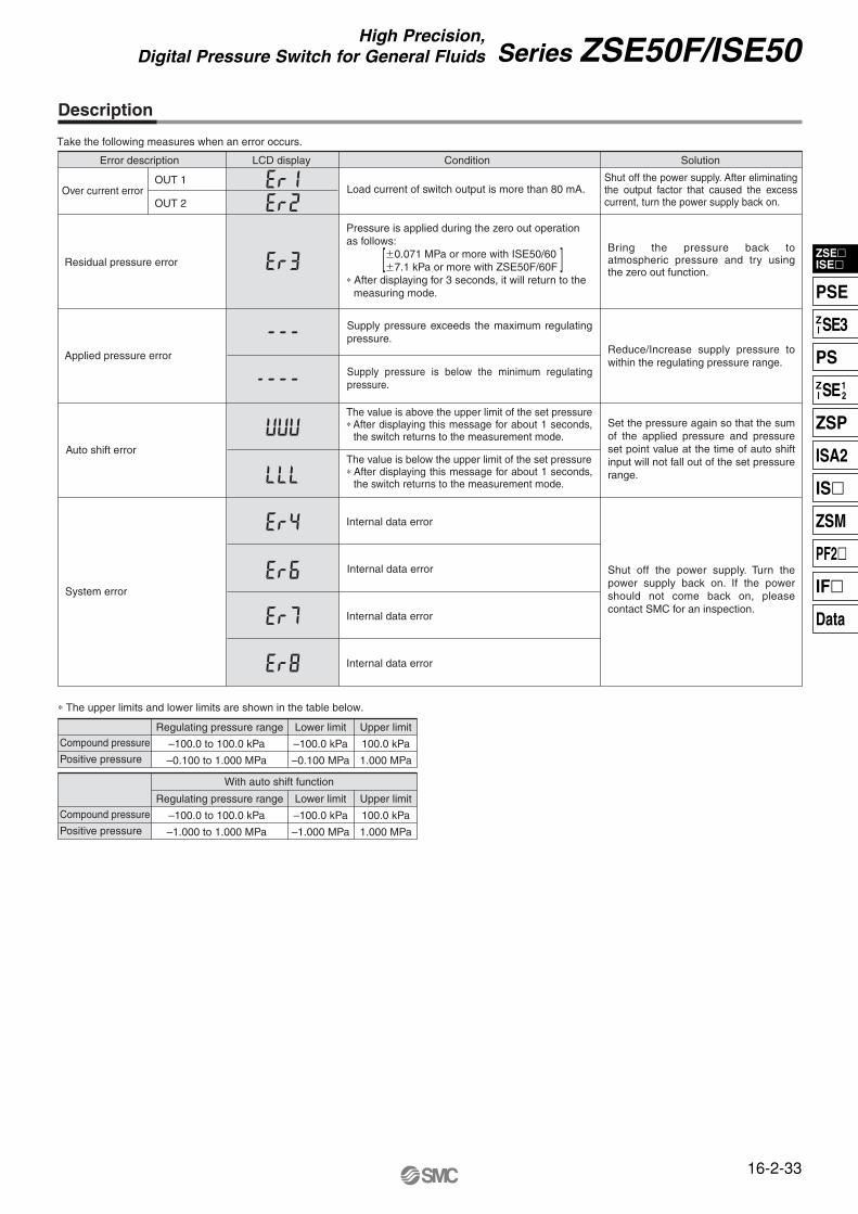
Description
Error description
Over current error
Residual pressure error
Applied pressure error
Auto shift error
System error
Compound pressure Regulating pressure range
–100.0 to 100.0 kPa
–0.100 to 1.000 MPa
Lower limit
–100.0 kPa
–0.100 MPa
Upper limit
100.0 kPa
1.000 MPa
OUT 1
OUT 2
LCD display Condition Solution
Take the following measures when an error occurs.
∗ The upper limits and lower limits are shown in the table below.
Load current of switch output is more than 80 mA.
Pressure is applied during the zero out operation as follows:
0.071 MPa or more with ISE50/607.1 kPa or more with ZSE50F/60F
∗ After displaying for 3 seconds, it will return to the measuring mode.
Supply pressure exceeds the maximum regulating pressure.
Supply pressure is below the minimum regulating pressure.
Internal data error
Internal data error
Internal data error
Internal data error
Shut off the power supply. After eliminating the output factor that caused the excess current, turn the power supply back on.
Bring the pressure back to atmospheric pressure and try using the zero out function.
Reduce/Increase supply pressure to within the regulating pressure range.
Set the pressure again so that the sum of the applied pressure and pressure set point value at the time of auto shift input will not fall out of the set pressure range.
Shut off the power supply. Turn the power supply back on. If the power should not come back on, please contact SMC for an inspection.
With auto shift function
Regulating pressure range
–100.0 to 100.0 kPa
–1.000 to 1.000 MPa
Lower limit
–100.0 kPa
–1.000 MPa
Upper limit
100.0 kPa
1.000 MPa
The value is above the upper limit of the set pressure ∗ After displaying this message for about 1 seconds,
the switch returns to the measurement mode.
The value is below the upper limit of the set pressure ∗ After displaying this message for about 1 seconds,