High Pressure Ethanol Reformingfor Distributed H2 Production
S. Ahmed and S.H.D. Lee
Bio-Derived Liquids to Hydrogen Distributed Reforming Working Group
Kickoff Meeting October 24, 2006, Baltimore, Maryland
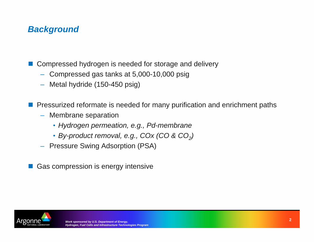
Background
� Compressed hydrogen is needed for storage and delivery – Compressed gas tanks at 5,000-10,000 psig – Metal hydride (150-450 psig)
� Pressurized reformate is needed for many purification and enrichment paths – Membrane separation
• Hydrogen permeation, e.g., Pd-membrane • By-product removal, e.g., COx (CO & CO2)
– Pressure Swing Adsorption (PSA)
� Gas compression is energy intensive
2Work sponsored by U.S. Department of Energy, Hydrogen, Fuel Cells and Infrastructure Technologies Program
40
The energy required to compress hydrogen to 6,000 psigcan be as high as 31% of the LHV of hydrogen
18.519.8
21.3
23.5
31.5
27.5
20
25
30
35
(%
)C
ompr
essi
on L
oss
/ LH
V
5-Stage Intercooled Compressor Compressor Efficiency: 70% Mechanical Efficiency: 97%
Electric Motor Efficiency: 90% FinalPressure: 6000 psi
Electricity Generation Efficiency = 40%
15
10
1 2 3 4 5 6 7 8 9 10
Initial Pressure of Hydrogen, atm
� Starting with a pressurized hydrogen / reformate stream lessens the energy required by the compressor
Note: Hydrogen from SMR-PSA processes may be available at 200 psig
3Work sponsored by U.S. Department of Energy, Hydrogen, Fuel Cells and Infrastructure Technologies Program
(SMR- Steam Methane Reforming; PSA – Pressure Swing Adsorption)
Steam reforming of liquid fuels generates a pressurized reformate with little energy penalty � Injecting liquid (ethanol + water) feeds into a high pressure reactor requires little energy � Hydrated ethanol is less expensive than fuel-grade ethanol
– Available upstream before water separation (distillation, adsorption, membrane)
6
5
4
� Steam reforming of ethanol at elevated pressure does not favor hydrogen yield, 3
however – Equilibrium predicts increasing 2
methane yields with increasing pressures 1
0 0 1000 2000 3000 4000 5000
H2
CO2 CO
CH4
T = 700°C, S/C = 3
Pressure, psia
Yiel
d, m
ol/m
ol o
f EtO
H
4Work sponsored by U.S. Department of Energy, Hydrogen, Fuel Cells and Infrastructure Technologies Program
The negative effect of pressure on hydrogen yield can be offset with higher temperature and steam-to-carbon ratio
46 S/C = 3, P = 2000 psia
35
H2
CO2
CH4
CO
T=700°C, P = 2000 psia
Yiel
d, m
ol/m
ol o
f EtO
H
Yiel
d, m
ol/m
ol o
f EtO
H
3
1
H2
CO2 CH4
CO 1
4
2 3
2
2 1
0 0 500 600 700 800 900 1000 1 2 3 4 5 6 7 8 9
Temperature, °C Steam-to-Carbon Molar Ratio
� High pressure-temperature combinations add to hardware cost � High steam-to-carbon ratio reduces overall process efficiency
5Work sponsored by U.S. Department of Energy, Hydrogen, Fuel Cells and Infrastructure Technologies Program
Simulated process efficiencies approach 70%at a steam-to-carbon ratio of 5
Burner
AirHydrogen
equilibrium Equilibrium Reactor �C2H5OH + xH2O(l)
Ethanol+Water
Exhaust
Membrane CO2, CO, H2, H2O(g), CH4, CnHm, … Separator
�Chemcad simulated process based on Heat – steam-reformer at equilibrium Exchanger
– hydrogen separation with membrane • 90% hydrogen recovery
– combustion of raffinate to generate heat 100
– heat exchange to reformer feeds 90 – exhaust at 200°C
80
�Efficiency decreases with increasing S/C 70
60 � Various alternative and more detailed
system solutions need to be evaluated 50
Ideal Reaction
Simulated Process (SR at 2000 psi)
5 6 7 8 9 10 Steam-to-C Ratio
Effic
ienc
y%
of L
HV
6Work sponsored by U.S. Department of Energy, Hydrogen, Fuel Cells and Infrastructure Technologies Program
A micro-reactor apparatus is being used to generate yield data
� Rated for 1,000 psi, 900°C � 63.5-mm (0.25-in) ID reactor tube � 4 wt% Rh/ La-Al2O3
� Powder, 150-250 μm � 0.35 g of catalyst � 20-mm long-catalyst bed
7Work sponsored by U.S. Department of Energy, Hydrogen, Fuel Cells and Infrastructure Technologies Program
Vaporizer tests indicate the ethanol starts decompositionabove 440°C
1
CO
CH4
C2H4
C2H6
1000 psig S/C=12
1000 psig S/C=20
500 psig S/C=20
Exit
T =
440°
C
Exit
T =
470°
C
� At 1000 psig, S/C = 12-20 0.9 – BP = ~310°C
Con
cent
ratio
n, %
(N2-
free
) 0.8 � At 500 psig, S/C = 12-20
0.7– BP = ~255°C 0.6
0.5
0.4
0.3
0.2
0.1
0 250 350 450 550
Time, min
8Work sponsored by U.S. Department of Energy, Hydrogen, Fuel Cells and Infrastructure Technologies Program
The hydrogen yield with the nickel catalyst decreasedwith time, indicating deactivation of the base metal catalyst
� The nickel catalyst deactivated with time – Bed pressure drop increased – Carbonaceous deposits were
observed in the reactor
� The reactor was re-packed with a rhodium catalyst – 4 wt% Rh / La-Al2O3
� The rhodium catalyst performed better – Higher hydrogen yield – Maintained activity
Yiel
d, m
ol/(m
ol E
tOH
)
T=650°C, P=1,000 psig, S/C=12, GHSV=84,000 /hr 4.5
4.0
3.5
3.0
2.5
2.0
1.5
1.0
0.5
0.0
Rh - H2
Ni - H2
Ni - CH4
Rh - CH4
0 100 200 300 400Time, min
9Work sponsored by U.S. Department of Energy, Hydrogen, Fuel Cells and Infrastructure Technologies Program
The nickel catalyst yielded a considerable fraction ofcondensable products
� The Ni catalyst yielded more undesirable hydrocarbons
– Mass balance accounted for 76% of the carbon
• Condensable products and carbon deposits could not be factored in
� The Rh catalyst yielded more hydrogen and COx, the desired product species
Catalyst Ni Rh Temperature, °C 650 650 Pressure, psig 1000 1000 GHSV, /hr 83,000 83,000 Steam-to-Carbon 12 12 Product Yield
H2, mol/(mol EtOH) 2.4 3.9 CO, mol/(mol EtOH) 0.2 0.1 CH4, mol/(mol EtOH) 0.5 0.6 CO2, mol/(mol EtOH) 0.8 1.4 C2H4, mol/(mol EtOH) 0.006 ND C2H6, mol/(mol EtOH) 0.029 ND
Carbon Balance, % 76 101
ND – not detected
10Work sponsored by U.S. Department of Energy, Hydrogen, Fuel Cells and Infrastructure Technologies Program
Experimental data show multiple hydrocarbon species inthe product stream
� With increasing pressure 5 – Hydrogen yield decreases – Methane yield increases 4 – Ethylene is hydrogenated to
produce ethane
Yiel
d, m
ol/(m
ol E
tOH
)
/()
C2H6
C2H4
COx
H2
CH4
/
0.00
0.02
0.04
0.06
0.08
0.10
Yiel
d, m
olm
ol E
tOH
T=650°C, S C=6, GHSV=15,000 /hr, Rh catalyst
3
2
1
0
0 500 1000Pressure, psig
11Work sponsored by U.S. Department of Energy, Hydrogen, Fuel Cells and Infrastructure Technologies Program
The experimental hydrogen yield approaches equilibriumpredictions at 1000 psi
� At a constant GHSV, equilibrium is approached at higher pressures
– Faster reaction rates
Yiel
d, m
ol/(m
ol E
tOH
)
S/C=6, GHSV=15,000 /hr, Rh catalyst 6
5
4
4.26
0.76
0.09
2.17
0.94
0.71
0.24
0.64
20 psi-Equil
20 psi-Exp
1000 psi-Equil
1000 psi-Exp
3
2
1
0 H2 CO2 CO CH4
12Work sponsored by U.S. Department of Energy, Hydrogen, Fuel Cells and Infrastructure Technologies Program
The product species can be explained through acombination of reactions
1. Ethanol Dehydrogenation : C2H5OH = CH3CHO + H2
2. Ethanol Dehydration : C2H5OH = C2H4 + H2O 3. Dissociative Ads. of Water : C2H5OH + H2O = CH3COOH + 2H2
4. Acetaldehyde Dissociation : CH3CHO = CO + CH4
5. Ethanation : C2H4 + H2 = C2H6
6. Dissociation of Acetic Acid : CH3COOH = CH4 + CO2
7. Methane Steam Reforming : CH4 + H2O = CO + 3H2
8. Water Gas Shift : CO + H2O = CO2 + H2
13Work sponsored by U.S. Department of Energy, Hydrogen, Fuel Cells and Infrastructure Technologies Program
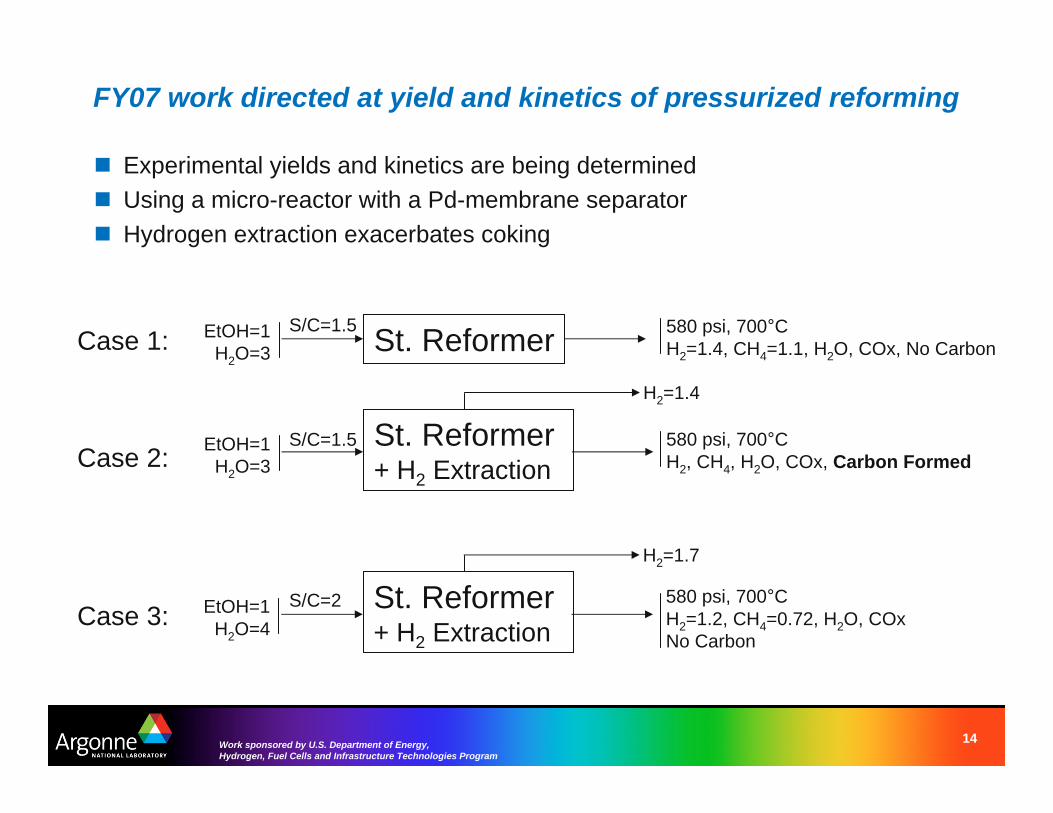
FY07 work directed at yield and kinetics of pressurized reforming
� Experimental yields and kinetics are being determined � Using a micro-reactor with a Pd-membrane separator � Hydrogen extraction exacerbates coking
Case 1: EtOH=1 H2O=3
Case 2: EtOH=1 H2O=3
Case 3: EtOH=1 H2O=4
St. Reformer
S/C=1.5
S/C=1.5 580 psi, 700°C H2=1.4, CH4=1.1, H2O, COx, No Carbon
H2=1.4
St. Reformer + H2 Extraction
580 psi, 700°C H2, CH4, H2O, COx, Carbon Formed
H2=1.7
St. Reformer + H2 Extraction
S/C=2 580 psi, 700°C H2=1.2, CH4=0.72, H2O, COx No Carbon
14Work sponsored by U.S. Department of Energy, Hydrogen, Fuel Cells and Infrastructure Technologies Program
How worthwhile is the pressurized steamreforming of bio-liquids? � We are currently seeking an answer for ethanol
– Experimental yields and kinetics are being determined • Using a micro-reactor with a Pd-membrane separator
– Reactor models will help extract kinetic information – Supported by new generation of catalysts
• Improve durability and reduce cost
� System model and analysis – Simple membrane reactor concept – Alternative purification / enrichment options – Go / NoGo determination on pressurized reforming with ethanol
15Work sponsored by U.S. Department of Energy, Hydrogen, Fuel Cells and Infrastructure Technologies Program
Acknowledgments
� R.K. Ahluwalia � M. Ferrandon � T. Krause
This work was supported by the US Department of Energy’s Hydrogen, Fuel Cells and Infrastructure Technologies Program in the Office of Energy Efficiency and Renewable Energy.
This presentation has been created by UChicago Argonne, LLC, Operator of Argonne National Laboratory (“Argonne”). Argonne, a U.S. Department of Energy Office of Science laboratory, is operated under Contract No. DE-AC02-06CH11357. The U.S. Government retains for itself, and others acting on its behalf, a paid-up nonexclusive, irrevocable worldwide license in said article to reproduce, prepare derivative works, distribute copies to the public, and perform publicly and display publicly, by or on behalf of the Government.
16Work sponsored by U.S. Department of Energy, Hydrogen, Fuel Cells and Infrastructure Technologies Program