Journal of Physical ScienceandApplication1(20 1 1)1 5.28 LOW-Loss DielectricMaterial CharaCteriZationand 薅 黪 蠛 High·-Q Resonator Designfrom MicrowavetoMillimetre W aves Frequencies Jean-M ichel LeFloch ,M ichael E.Tobar。 , GeorgesHum bert2 , DavidM ouneyrac。一 , DenisF6rachou2 . Romain Bara,M ichel Aubourg ,JohnG.Hartnett , DominiqueCros。 , Jean—M arcBlondy。andJerzyKrupka3 School ofPhysics,UniversityofWestern Australia,35StiflingHwy , 6009 Crawley,W e ternA“ tr日,f。 XLIM,UMRCNRSNo6172 , 123av.A.Thomas,87060LimogesCedex . Frn,2ce 3·InstituteofMicroelectronies andOptoelectronics Warsaw UniversityofTechnology , Ko ykD n75 Warsnw Pol nd Received:M arch25,20 1 1/A ccepted:April 08 , 20 1 1/Published:June 1 5,20 1 1 Abstract:Dielectric resonatorsarekey componentsin many microwaveandmillimetrewavecircuitsandapplications . including n。gn‘ rlltesandf requency‘determiningelementsfor precisionfrequencysynthesis M ultilayeredandbulklow.1oss singlecrystal and polycrystalline dielectric structures haye become very importantfor designing these devices . Proper design requires careful electromagneticcharacterisationoflow lossmaterial properties Thisincludes exact simulationwithprecisionnumerical softwareand precisem easurementsolresonant modes.Forexample,wehavedevelopedtheW hisperingGallery modetechnique , whichhasnow becomethestandardforcharacterizing Iow-lossstructures Thispaperwill review someof thecom moncharacterisationtechniques usedinthemicrowavetomillimetrewavef requencyregime . Keywords:Dielectricresonator,Braggmode,whisperinggaUer y m ode , bulkandthinf ilm characterization 1.IntrOducti0n Dielectricresonators(DR)arethe key elementin mosttelecommunicationssystems,which allow fora better reception and more customers on the sam e comm unication bandwidth.They are also very useful in many industries that require radar detection , proximity detection,as well as military based applicationslikesecuretransmissions,remoteguiding , navigation and positioning systems(i.e.,GPS and Galileo [1,2]).Also,to realize precise time and f requency references,it is necessar y to design microwave sources with high spectral purity and precise f requency stability[3—1 31.These characteristics are directly related to the quality of the resonant COrresponding author:Jean—Michel Le Floch,Ph.D ., research f ields: dielectric characterisation, thin f ilm , computational physics, microwave and millimetrewave technologies.E-mail:lef ioch@cyllene.uwa.edu.au element,such as the cryogenic sapphire oscillator (cso),whichis basedonanultra-high—Q-factor(-10) sapphireDR.Theseoscillatorsareusedas asecondary f requency reference and are capable of pulsing a primar y standard (caesium fountain clock) atthe quantum noiselimit[14,151.CSOshavealsobeen developed to testfundamentalPhysics.such as a modem Michelson-Morley localLorentz Invariance tests,using either orthogonal modes or a double dielectricsapphireresonators[1 6-1 8].Theexperiment searchesfora differencejn thespeed oflightin two orthogonal directions:parallel to,andperpendicular to , themotionof theEar th aroundtheSun. Depending on the application,the requirementon materiaI propertiesandsizeof thedielectric.themake upof theresonatorcanvar y substantially.Tomakethe rightchoice of materiaIand dimensions itis very impor tantto use precise experimentaland numerical
Transcript
Journal of Physical Science and Application 1(20 1 1)1 5.28
LOW-Loss Dielectric Material CharaCteriZation and
薅 黪 蠛
High·-Q Resonator Design from Microwave to Millimetre
W aves Frequencies
Jean-Michel Le Floch ,M ichael E.Tobar。,Georges Humbert2
,David M ouneyrac。一
,Denis F6rachou2
. Romain
Bara ,M ichel Aubourg ,John G.Hartnett ,Dominique Cros。
,Jean—Marc Blondy。and Jerzy Krupka3
· School ofPhysics,University of Western Australia,35 Stifling Hwy,6009 Crawley,We tern A“ tr日,f。
case we use the Method ofLines[19].The formulas for
both pe and G are given below in Eqs.(4)and(5)and
also their dependence on azimuthal mode number is
shown in Fig.7.
pe
G =
(I) poH dV
v
Wemn_erl
WeT0tdi
H H:dS
m E ·E dV
静( ) ·E dV (5)
The general form ulas to determine the intrinsic
properties of the material are as follows:
Q =Q +Q +Q :
(6)
Q。=Q上+( + :)Q
where Qo is the unloaded Q—factor,QL is the loaded
o eom etric tactor
E;!;i ; i ; ; i; 。 ; j!;j ;: ; ! ! j ;j_一一 。! !j j ; i i ;
— ri i !
i ;; ㈡ ; — ; :i i i i: i:.-,I ! i;!
! i i ! ; —
, j i : ;
; ! ; , : i ! ; j; ; i j ; i; j;i i;i; ; ;;!
l j ;i ;i ■ j i; i i ;;i! i; —I ; ㈡ ;;; { !i: : ;: 。i i ; ;; ;: ;!
i ! 。- !; !㈠ ; ! 二● ; i; i ! j i i i!
! J i i i!
! j , j ;;; ; i ㈡ ;i :!: ;; ; ㈡ ; i
!;一 : ; : ;; ;i ! ; i ;; ;!
! i i i i j ; j
O 10 2O 3O 40 50
Azimuthal mode nutuber lm,
Fig.7 (1eft)Evolution of the Geometric factor(G)
(Pe)vs the azimuthal mode number(m).
19
Q—factor,pl,2 the probe coefficients.
To ensure the measurement of the intrinsic
material properties the cavity needs to be well
under—coupled(13<<1).That means the contribution
from the probes(ie.external losses)to the total losses
is negligible.Then the measurement given by the
loaded cavity Q-factor( )will be equal to the
unloaded Q—factor(Qo),which is essentially only the
contribution from the dielectric( ,)and the cavity
wall losses(Q ).
≈0 Q ≈Q =Q二 +Q (7)
Q :∑N tan + (8) l U
The dielectric Q—factor is given by the electric
energy filling factor PP,and the material loss tangent.
The metallic Q-factor Om is determined from the
Geometric factor G and the surface resistivity Rs[Units
Ohms]ofthe material used to make the metallic cavity.
The latter is related to the conductivity(o)of the metal
and the chosen mode resonance frequency co/2rc[Hz】
(see Eq.(8)).
尺 : w = (9)
The surface resistivity is obtained by measuring
the empty cavity,i.e.,the cavity without the sample.
Then it is straight forward to deduce the loss tangent of
the materia1.Determination of the permittivity of the
1
0鹪
O 舀0
0 g7
O 95
o 94
lIl 孽 F箨ctor
鼬 商舞端掷 n t i“H 0
:
勰:
* 叫盘蚺一
:黜
一
静;
60 0 辔 蛙 0站 40 囝 国
AzlmuthaI mode I1umber《mJ
vs the azimuthal mode number(m)'(right)Evolution ofthe filling factor
,
~
一 器嚣饔 :I 矗鞲‰
l。lJ暑篙!1 笛基
20 Low-Loss Dielectric Material Characterization and High-Q Resonator Design from Microwave to
Millimetre W aves Frequencies
sample is achieved by retro—simulation using Finite
Element Analysis,Mode M atching or,in our case,the
Method ofLines[191.
The W G method can be used for both isotropic and
uniaxially anisotropic materials with a thickness of a
few cm to a few mm.This is the most accurate
technique to determine the intrinsic properties of the
sample due to the fact that the electric energy fil ling
factor P in the dielectric tends to unity for a large
azimuthal mode number.However,this method is not
applicable to samples with thicknesses below a few
mm,because the excitation of whispering gallery
modes is not possible with flat aspect ratios.
3.2 Transverse Electric Mode Technique
In this section, we present the technique for
characterizing dielectric samples from a few gm to a
few mn【28,29].The measurement is done in three
steps using the fundamental transverse electric mode
(TE0 1 0.The method consists of inserting a dielectric
sample through a slot into a cylindrical cavity where
the electric field is maximum,and then measuring the
perturbations in frequency and Q—factor.In this case we
may want to characterize a substrate with a dielectric
deposition only nm thick.
Step 1 consists of measuring the properties of the
cavity itselfi This allows us to know the conductivity of
the metal and calibrate the simulation software for the
successive measurements.These determine the initial
conditions for the measurement.The initial Q—factor
has to be very high in case of measuring very low loss
materials and therefore should not being limited by the
cavity.This calculation is related by the previous Eqs.
(5)一(8).
Step 2,we insert the substrate carefully and slowly to
be sure to track the resonance mode frequency shift in
order to deduce the right permi~ivity by
retro simulation.The drop in the value of the Q—factor
indicates the lOSS contribution from the dielectric
substrate used in the next step to measure the properties
of the thin film deposition.Hence we can deduce the
loss tangent of the substrate from
Q..一—R—
s
tan :— — (10) pe
Finally the step 3,we insea the same substrate with a
thin layer of material deposited only a few nm thick.In
the same way we determine the permi~ivity and the
loss tangent ofthe thin film materia1.
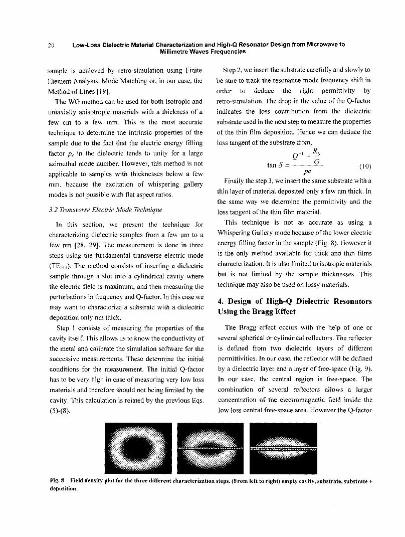
This technique is not as accurate as using a
Whispering Gallery mode because ofthe lower electric
energy filling factor in the sample(Fig.8).However it
is the only method available for thick and thin films
characterization.It is also limited to isotropic materials
but is not limited by the sample thicknesses.This
technique may also be used on lossy materials.
4.Design of High—Q Dielectric Resonators
Using the Bragg Effect
The Bragg effect occurs with the help of one or
several spherical or cylindrical reflectors.The reflector
is defined from two dielectric layers of different
permi~ivities.In our case.the reflector will be defined
by a dielectric layer and a layer of free—space(Fig.9).
In our case,the central region is free-space.The
combination of several reflectors allows a larger
concentration of the electromagnetic field inside the
low 1oss centra1 free—space area.However the Q.factor
一 一 一 Fig.8 Field density plot for the three different characterization steps.(From left to right)empty cavity,substrate,substrate+
deposition.
Low-Loss Dielectric Material Characterization and High-Q Resonator Design from Microwave to
Millimetre Waves Frequencies
Spherical case Cylindrical case Fig.9 Spherical and cylindrical Bragg resonators design for a,m layer structure.
enhancement iS not SO significant after the addition of
the first three Bragg reflectors.This is due to the
dielectric loss added by the Bragg reflectors[7—1 2].
The order of the field confinement within the central
area with this type of structure by using three Bragg
reflectors iS about 9O%.
The design of high-Q dielectric resonators using a
Bragg effect is significant for room temperature
resonators as the field trapped in the free—space inner
region of the structure does not increase the Q—factor.
In the following we summarize the work done on the
design of Bragg resonators with two different
topologies, spherical and cylindrical cases
respectively.
4.1 Spherical Bragg Resonator
In order to realize a spherical Bragg resonator,we
impose boundary conditions between layers.First we
A
础 谤
21
study the fundamental TE mode without azimuthal
variation,without taking into account the propagating
mode in the dielectric.W e assume the separation of
variables jn spherical coordinates is valid and the field
pattern can be decomposed along one propagation
direction.The spherical Bessel function goes to zero at
the interface of the reflector and the edge of the cavity
and has a maximum value at the interface
dielectric/flee—space interface in the reflector,region 2
and 3(see Figs.10 and 1l、.The region 1 is free space.
The right.hand side of Fig.1 0 illustrates the one
dimensional representation[1 1,1 2].The left—hand side
figure shows the field pattern ofthe fundamental Bragg
mode in a spherical cavity with anti—resonance in the
reflector and resonance in the centraI region.
The frequency and wave number of the resonator iS
determined in a similar way to a mode in an empty
cavity and iS given by:
0 .薹
噻
—
。慧
八 凰 豳 囡
o 2 4 & 8
Fig.10 (1eft)Density plot of the spherical Bragg cavity where the field is highly confined in region 1 with an anti。resonance
between 2 and 3,defined as a resonator.The right figure shows the simple modeling of the field pattern in 1D.
22 Low’Loss Dielectric Material Characterization and High-Q Resonator Design from Microwave to
Millimetre W aves Frequencies
Fig·1 1 Realisations of spherical Bragg resonators made with Teflon and YAG crystal(right picture).
where 一
r
here xl is the first root ofthe spherical Bessel function.
The wave number also may be calculated in all the
other regions subject to the“qua~er wavelength”
analogy.For evenly numbered regions we calculate:
k2,= +、一
|
一
H
) for i:1 to J 02)
For odd numbered regions,we calculate
』}2,+.= Z +1一 l ( 卜̈一 ,) for i:1 to j(13)
Here J is the number of Bragg reflector pairs.For
example iU 1 there is one Bragg reflector pair given
by region 2 and 3,and-f,=2 the second pair will be
given by region 4 and 5.The reflectors must c0me in
pairs to ensure the cancellation of the field in the
reflectors.Also, ’,iS the ith root ofthe derivative ofthe
Fig.
Sch
Bessel function and is the fth root of the Bessel
function.To calculate the ~equency and necessary
dimensions the wave number in all regions must be
equated.
Experimentally a Q·factor of about 22,000 was
measured with a single Teflon layer Bragg resonator at
1 3.8 GHz which by scaling the parameters to a sapphire
crystal,should result in a Q.factor of about 260。000
(Fig.1 2,Table 1).This is similar for a sapphire
dielectric W G mode resonator at this frequency.
The comparison between simulation and the
measured results clearly shows that the concept of the
spherical Bragg resonator has been successfully
demonstrated.The main limitation on the Q..factor is
the dielectric loss of the Teflon, An enhancement Of
Q—factor was obtained with respect to a dielectric
resonator limited by the loss tangent of the materia1.
囤 }川{z 黼 #船 :
i
/ \
. \ .
gg spherical resonator made in Teflon,(right)
Low-Loss Dielectric Material Characterization and High·Q Resonator Design from Microwave to 23
Millimetre Waves Frequencies
Table 1 Results from simulation and measurement ofa single Bragg spherical resonator.
This Q—factor of 22.000 is 3.5 times greater than the
loss tangent limit and is due to the trapping ofthe field
in the vacuum of the inner free—space region.
The Q.fproduct for a crystal YAG is about 6×10 .
Using this parameter we carl determine the
enhancement of Q—factor obtained(Fig.1 3),which is
3.9 times greater than the lOSS tangent limit.
.2 Cylindrical Bragg Resonator
W e also investigated cylindrical Bragg resonator
structures.To establish the design model we assume
the fundamental transverse electric mode.We also
assume that separation of variables iS valid in
cylindrical coordinates SO the field pattern can be
decomposed into both propagation directions.r and z.
The solutions require a Bessel function in the radial
direction and a sine function in the axiaI direction.Both
鞯
是8
f
嚣麓羹 臻臻 鑫 臻棼, 辩£ 一4釜 礴 d棼
functions go to zero at the interface ofthe reflector and
at the edge of the cavity.They are maximized within
the Bragg reflector at the interface ofthe dielectric and
free—space[8,9].The field density plot shows both
anti—resonance in the reflectors and high field
confinement in the central part of the resonator(Figs.
14 and 15、.
A linear combination of modes was discovered,
which links both directions with the following
parameter),.
7/"
2
厶 , ’J6
1i /~,1,1
赤 4 『-l
i J商 2004 00l5臻i 0巷
囊: 穆棼O0翻器 氛 0谚嵇棼谚秘 秘棼零 尊辩嚣
圆 Hz ( o~ 1 05 ,000 器 巷鼋张群
霪
妻毒
. 、
7 ⋯ F
、
。
H 一 )
CH1卷辩N鬟~ k盛童e 嚣
棼 蛰2495 霉 巷瓣嚣
瓢 2黪≯盏8誊叠 3臻拇z
臻 置臻 嚣蠢虢
铸巷嘻{~42 §:旗霉 堪嚣
Fig.13 M easurement in transmission at room ternperature of a single Bragg spherical resonator made in crystal YAG·
一.一 ll
屯
24 Low.Loss Dielectric Material Characterization and High-Q Resonator Design from Microwave to
Millimetre Waves Frequencies
1、、
.
‘
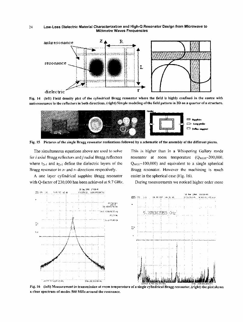
Fig.1 4 (1eft)Field density plot of the cylindrical Bragg resonator where the field is highly confined in the centre with
anti.resonance in the reflectors in both directions.(right)Simple modeling ofthe field pattern in 2D on a quarter ofa structure.
圈 囹岛 匕 I lp d_e 口"reflml s=RTet'~ Fig.15 Pictures ofthe single Bragg resonator realisations followed by a schematic ofthe assembly ofthe different pieces.
The simultaneous equations above are used to solve
for i axial Bragg reflectors andj radial Bragg reflectors
where t2i..1 and a2j..1 define the dielectric layers of the
Bragg resonator in Z—and r—directions respectively.
A one layer cylindrical sapphire Bragg resonator
with O.factor of 230,000 has been achieved at 9.7 GHz
抟 帮 :辩e { 辩 啦
萋 鼢 辣 登攥5赣 黧 #燕 # 鲢 氅
辩∥ 3密 .秘辅 ?氍 辅
⋯ 碰i‰ 鹞 群甜
: 积 j
/ . ‘
一 \
§ 糍 畦e搴萼 秘 融
This is higher than in a W hispering Gallery mode
resonator at room temperature (QwGH--200,000,
QWGE--1 00,000)and equivalent to a single spherical
Bragg resonator。However the machining is much
easier in the spherical case(Fig.1 6).
During measurements we noticed higher order more
}# , 日
蕊 赫 《
{ 》
; 郾 s蠢
ll
篱
{
§%蠊 }{《
0 ,i; *
Fig.16 (1eft)Measurement in transmission at room ternperature ofa single cylindrical Bragg resonator,(right)the plot shows
a clear spectrum of modes 500 M Hz around the resonance.
Low·Loss Dielectric Material Characterization and High·Q Resonator Design from
Millimetre Waves Frequencies
confined modes existed,and by combining modeling
and machining different size cavities we observed the
following modes as shown in Figs.17 and 18.
The mode properties shown in Fig.1 8 have two
variations in the central region and one in the reflectors.
The Q—factor iS about 94.000 at 1 2.4 GHz.which iS
equivalent to a W GE mode resonator at room
temperature.However the spectrum 500 M Hz around
the resonance iS overmoded.
Following the modeling of simple Bragg resonator,
we added a second reflector.This was made from
alumina in order to prove the principle.However the
field is SO confined into the centre it has been impossible
for US to couple to the high—Q mode(estimated to be
500,ooo).During the characterization ofthe alumina we
have discovered a high Q—mode at 1 3.4 GHz(Fig.1 9)
which is a hybrid and Bragg like mode with an
azimuthal number )different to =2)[7】.
要 n :Radlalm odenum ber
聪l:矗 娃出 l {o e nt=l f
P :Axialt3"lod~ lumber
:Ra磁盘lmodenm啦》erintothe reflecto~
s; m odenumberintothe reflect0r
Fig.17 Electric field density plots calculated using the method of lines software I19J of the three different Bragg modes.
3土摊种 2瓣S t9~44i42
窭 Hz
益 ㈨ _
、 j
\
》 II l
|
m {
镶 i器 瓣艇 麓8鹣 鞲
:.{裁l{∞辩 辅2
嚣瓣鲢?,
l0§彗*§麓?瓣
盍
瓤 H 2蛳g j4 ∞
l m 、
}
l 黼 ; = i ’
j f { ⋯
淫 锺 瓣 i 髓$《辩 《 献 。§帮 弱9§辕甚
Fig.18 (1eft)Measurement in transmission at room temperature of the second Bragg mode of the Fig.18,(right)500 MHz
span around the resonance.
1
26 Low-Loss Dielectric Material CharacterjzatiOn and High-Q Resonator Design from Microwave to
Millimetre Waves Frequencies
0, St 2∞ £ iel{S;22
麓嚣 L赫 《#/ 蓼 螓爨 曼0 璺尊 警i黪
umina 麓 绀 n 0辅 e《躺 0§鞲{z
i越8j‰
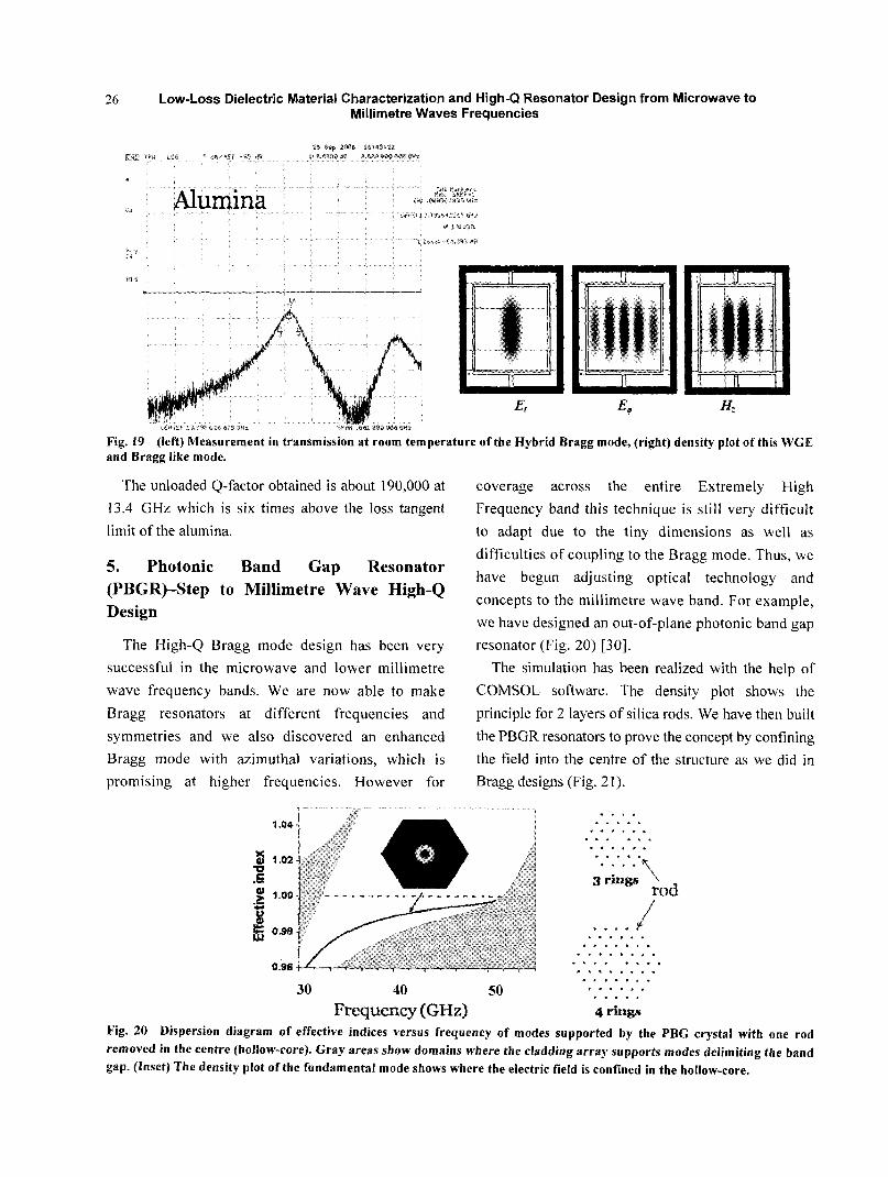
国回画 Fig.19 (1eft)Measurement in transmission at room ternperature ofthe Hybrid Bragg mode,(right}density plot ofthis WGE and Bragg like mode.
The unloaded Q—factor obtained is about 1 90,000 at
1 3.4 GHz which is six times above the loss tangent
limit of the alumina.
5. Photonic Band Gap Resonator
(PBGR)-Step to Millimetre Wave High—Q Design
The High—Q Bragg mode design has been very
Successful in the microwave and lower millimetre
wave frequency bands.W e are now able to make
Bragg resonators at different frequencies and
symmetries and we also discovered an enhanced
Bragg mode with azimuthal variations,which is
promising at higher frequencies. However for
'。a4
1 O2
,+00
O 孽8
O.86
coverage across the entire Extremely High
Frequency band this technique is still very difficult
to adapt due to the tiny dimensions as well as
diffi culties of coupling to the Bragg mode.Thus,we
have begun adjusting optical technology and
concepts to the millimetre wave band.For example,
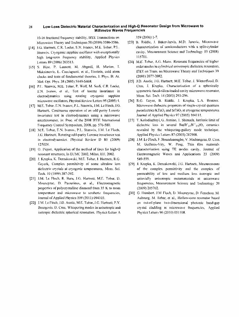
we have designed an out—of-plane photonic band gap
resonator(Fig.20)[30].
The simulation has been realized with the help of
COM SOL software. The density plot shows the
principle for 2 layers of silica rods.W e have then built
the PBGR resonators to prove the concept by confining
the field into the centre of the structure as we did in
Bragg designs(Fig.2 1).
30 40 50
Frequeney(GHz)
· · -
3 rings \
ro娃
4rings
Fig·20 Dispersion diagram of effective indices versus frequency of modes supported by the PBG crystal with one rod
removed in the centre(hollow-core)·Gray areas show domains where the cladding array supports modes delimiting the band
gap.(Inset)The density plot of the fundamental mode shows where the electric field is confined in the boll0w.c0re.
器 一 ≯一 ∞:l熬
Low_Loss Dielectric Material Characterization and High-Q Resonator Design from Microwave to
Millimetre Waves Frequencies
re键uency‘gHz)
Fig.2 1 M easurement in transmission at room temperature of a 3 and 4 rod.1ayers.
The resonator has been made with silica rods.The
resonance has been found at 30 GHz,the 0一factor
obtained was about 5.000 with 4 Iayers of rods.The
Q—factor for a dielectric Ioaded cavity depends on the
electric energy filling factor, the metal surface
resistance,and the geometric factor of the mode.For
our case the Q.factor is mainly limited by the metallic
walllosses rather than the IOSS tangent.
6.Conclusions
This paper has reviewed some of the techniques
achieved at microwave, and millimetre wave
frequencies to design high—Q dielectric loaded
resonators, and to characterize their material
properties.
Reference
[2】
【3J
[4】
C. Rieck, P.Jarlemark,R. Emardson, K.Jaldehag,
Precision of time transfer using GPS carrier phase.in: