High quality chalcogenide-silica hybrid wedge resonator
GUMIN KANG,1,5 MOLLY R. KROGSTAD,2 MICHAEL GRAYSON,1 DAE-GON KIM,3 HANSUEK LEE,3 JULIET T. GOPINATH,1,2,4 AND WOUNJHANG PARK
1,4,* 1Department of Electrical, Computer & Energy Engineering, University of Colorado, Boulder, Colorado 80309, USA 2Department of Physics, University of Colorado, Boulder, Colorado 80309, USA 3Graduate School of Nanoscience and Technology, Korea Advanced Institute of Science and Technology, Daejeon 34141, South Korea 4Materials Science & Engineering Program, University of Colorado, Boulder, Colorado 80309, USA 5Present address: Nanophotonics Research Center, Korea Institute of Science and Technology (KIST), Seoul 02792, South Korea *[email protected]
OCIS codes: (140.3948) Microcavity devices; (160.2750) Glass and other amorphous materials; (160.4330) Nonlinear optical materials; (160.6840) Thermo-optical materials; (280.6780) Temperature.
References and links
1. S. M. Grist, S. A. Schmidt, J. Flueckiger, V. Donzella, W. Shi, S. Talebi Fard, J. T. Kirk, D. M. Ratner, K. C. Cheung, and L. Chrostowski, “Silicon photonic micro-disk resonators for label-free biosensing,” Opt. Express 21(7), 7994–8006 (2013).
2. X. Jiang, C. Yang, H. Wu, S. Hua, L. Chang, Y. Ding, Q. Hua, and M. Xiao, “On-chip optical nonreciprocity using an active microcavity,” Sci. Rep. 6(1), 38972 (2016).
3. P. Del’Haye, T. Herr, E. Gavartin, M. L. Gorodetsky, R. Holzwarth, and T. J. Kippenberg, “Octave spanning tunable frequency comb from a microresonator,” Phys. Rev. Lett. 107(6), 063901 (2011).
4. M. R. Krogstad, S. Ahn, W. Park, and J. T. Gopinath, “Nonlinear characterization of Ge28Sb12Se60 bulk andwaveguide devices,” Opt. Express 23(6), 7870–7878 (2015).
5. M. Soltani, S. Yegnanarayanan, and A. Adibi, “Ultra-high Q planar silicon microdisk resonators for chip-scale silicon photonics,” Opt. Express 15(8), 4694–4704 (2007).
6. S. M. Spillane, T. J. Kippenberg, K. J. Vahala, K. W. Goh, E. Wilcut, and H. J. Kimble, “Ultrahigh-Q toroidal microresonators for cavity quantum electrodynamics,” Phys. Rev. A 71(1), 013817 (2005).
7. C. Wang, M. J. Burek, Z. Lin, H. A. Atikian, V. Venkataraman, I. C. Huang, P. Stark, and M. Lončar,“Integrated high quality factor lithium niobate microdisk resonators,” Opt. Express 22(25), 30924–30933 (2014).
8. X. Lu, J. Y. Lee, P. X. L. Feng, and Q. Lin, “Silicon carbide microdisk resonator,” Opt. Lett. 38(8), 1304–1306 (2013).
9. J. S. Sanghera, C. M. Florea, L. B. Shaw, P. Pureza, V. Q. Nguyen, M. Bashkansky, Z. Dutton, and I. D. Aggarwal, “Non-linear properties of chalcogenide glasses and fibers,” J. Non-Cryst. Solids 354(2-9), 462–467(2008).
10. B. J. Eggleton, B. Luther-Davies, and K. Richardson, “Chalcogenide photonics,” Nat. Photonics 5, 141–148(2011).
11. M. R. Krogstad, S. Ahn, W. Park, and J. T. Gopinath, “Optical characterization of chalcogenide Ge–Sb–Se waveguides at telecom wavelengths,” IEEE Photonics Technol. Lett. 28(23), 2720–2723 (2016).
12. X. Gai, B. Luther-Davies, and T. P. White, “Photonic crystal nanocavities fabricated from chalcogenide glass fully embedded in an index-matched cladding with a high Q-factor (>750,000),” Opt. Express 20(14), 15503–15515 (2012).
13. H. Lin, L. Li, Y. Zou, S. Danto, J. D. Musgraves, K. Richardson, S. Kozacik, M. Murakowski, D. Prather, P. T. Lin, V. Singh, A. Agarwal, L. C. Kimerling, and J. Hu, “Demonstration of high-Q mid-infrared chalcogenide glass-on-silicon resonators,” Opt. Lett. 38(9), 1470–1472 (2013).
14. M. W. Lee, C. Grillet, C. Monat, E. Mägi, S. Tomljenovic-Hanic, X. Gai, S. Madden, D.-Y. Choi, D. Bulla, B. Luther-Davies, and B. J. Eggleton, “Photosensitive and thermal nonlinear effects in chalcogenide photonic crystal cavities,” Opt. Express 18(25), 26695–26703 (2010).
15. Q. Du, Y. Huang, J. Li, D. Kita, J. Michon, H. Lin, L. Li, S. Novak, K. Richardson, W. Zhang, and J. Hu, “Low-loss photonic device in Ge-Sb-S chalcogenide glass,” Opt. Lett. 41(13), 3090–3093 (2016).
16. P. Klocek and L. Colombo, “Index of refraction, dispersion, bandgap and light scattering in GeSe and GeSbSe glasses,” J. Non-Cryst. Solids 93(1), 1–16 (1987).
17. J. Hu, N.-N. Feng, N. Carlie, L. Petit, A. Agarwal, K. Richardson, and L. Kimerling, “Optical loss reduction in high-index-contrast chalcogenide glass waveguides via thermal reflow,” Opt. Express 18(2), 1469–1478 (2010).
18. N. Carlie, J. D. Musgraves, B. Zdyrko, I. Luzinov, J. Hu, V. Singh, A. Agarwal, L. C. Kimerling, A. Canciamilla, F. Morichetti, A. Melloni, and K. Richardson, “Integrated chalcogenide waveguide resonators for mid-IR sensing: leveraging material properties to meet fabrication challenges,” Opt. Express 18(25), 26728–26743 (2010).
19. H. Lee, T. Chen, J. Li, K. Y. Yang, S. Jeon, O. Painter, and K. J. Vahala, “Chemically etched ultrahigh-Q wedge-resonator on a silicon chip,” Nat. Photonics 6(6), 369–373 (2012).
20. W. Bogaerts, P. De Heyn, T. Van Vaerenbergh, K. De Vos, S. K. Selvaraja, T. Claes, P. Dumon, P. Bienstman, D. Van Thourhout, and R. Baets, “Silicon microring resonators,” Laser Photonics Rev. 6(1), 47–73 (2012).
21. M. L. Gorodetsky, A. A. Savchenkov, and V. S. Ilchenko, “Ultimate Q of optical microsphere resonators,” Opt. Lett. 21(7), 453–455 (1996).
22. T. Miya, Y. Terunuma, T. Hosaka, and T. Miyashita, “Ultimate low-loss single-mode fibre at 1.55 μm,” Electron. Lett. 15(4), 106–108 (1979).
23. S. M. Spillane, T. J. Kippenberg, K. J. Vahala, K. W. Goh, E. Wilcut, and H. J. Kimble, “Ultrahigh-Q toroidal microresonators for cavity quantum electrodynamics,” Phys. Rev. A 71(1), 013817 (2005).
25. Fused Silica Material Properties, http://www.translume.com/index.php/resources/item/186-fused-silica-material-properties
26. L. He, Y. F. Xiao, C. Dong, J. Zhu, V. Gaddam, and L. Yang, “Compensation of thermal refraction effect in high-Q toroidal microresonator by polydimethylsiloxane coating,” Appl. Phys. Lett. 93(20), 201102 (2008).
27. H. S. Choi, S. Ismail, and A. M. Armani, “Studying polymer thin films with hybrid optical microcavities,” Opt. Lett. 36(11), 2152–2154 (2011).
28. B. Guha, J. Cardenas, and M. Lipson, “Athermal silicon microring resonators with titanium oxide cladding,” Opt. Express 21(22), 26557–26563 (2013).
29. P. Alipour, A. H. Atabaki, A. A. Eftekhar, and A. Adibi, “Athermal performance in titania-clad microresonators on SOI,” Frontiers in Optics 2010/Laser Science XXVI (2010), FThQ6.
30. J. D. Bradley, C. C. Evans, J. T. Choy, O. Reshef, P. B. Deotare, F. Parsy, K. C. Phillips, M. Lončar, and E. Mazur, “Submicrometer-wide amorphous and polycrystalline anatase TiO2 waveguides for microphotonic devices,” Opt. Express 20(21), 23821–23831 (2012).
31. B. A. Rose, A. J. Maker, and A. M. Armani, “Characterization of thermo-optic coefficient and material loss of high refractive index silica sol-gel films in the visible and near-IR,” Opt. Mater. Express 2(5), 671–681 (2012).
1. Introduction
High-Q optical microresonators, with the ability to confine optical fields inside a small volume for a long period of time, are essential building blocks for a wide variety of applications. These include label-free biosensors [1], integrated photonic devices [2], and freqeuncy combs [3, 4]. Devices have been demonstrated in a variety of materials including silicon [5], silica [6], lithium niobate [7], and silicon carbide [8]. The focus of our work is to develop high-Q microresonators with an attractive materials system, chalcogenide glass (ChG).
ChGs contain one or more chalcogen elements, and have many favorable optical properties including high refractive index, strong optical nonlinearity, wide infrared transparency (up to ~20um), and low nonlinear loss [4, 9–11]. ChGs can also be deposited at low temperature on a wide variety of substrates. For these reasons, ChGs are considered an excellent material family for near and mid-infrared nonlinear optical devices and photonic
crystal cavities and ring resonators based on ChGs have been reported [12–15]. Potential applications include high resolution spectroscopy for chemical and biological sensing, optical switching, and new infrared light sources. We focus on a particular chalcogenide material Ge28Sb12Se60, which is attractive due to the As-free composition and high glass transition temperature [16].
While ChGs exhibit promising material properties, the fabrication technologies, particularly etching recipes, are not mature. This results in rough surfaces, which in turn limit the achievable Q factors in microresonators. Thermal reflow of chalcogenide itself may significantly reduce roughness [17, 18], but thermal shrinkage and deformation of the material composition during the reflow process present challenges for precise control of the fabricated device geometry.
In this letter, we present a hybrid resonator design that takes advantage of the well-developed silica wedge resonator geometry, demonstrated with extremely high Q factor [19]. By simply depositing a ChG layer on silica wedge resonator, this enables chalcogenide resonators with high quality factors. Here, we report ChG-silica hybrid resonators with loaded Q’s of 105.
2. Methods
2.1 Device fabrication
Figure 1 shows the geometry and fabrication process for the chalcogenide-silica hybrid resonators. This fabrication process, up to the chalcogenide deposition, has been used to demonstrate Q factors as high as 875 million [19]. First, disk-shaped photoresist patterns are defined by photolithography onto the silicon wafer with 2 μm-thick thermal oxide. Then, the sample is immersed in buffered oxide etchant (BOE) to produce circular silica wedges. This wet etch step makes silica the surface extremely smooth and has been used to demonstrate Q factors as high as 875 million [19]. After removing the photoresist using organic solvent, the silicon substrate is dry etched by xenon difluoride (XeF2) to create air-suspended wedge structures. Finally, a 125 nm-thick chalcogenide glass film is thermally evaporated onto the silica wedge at a base pressure of 3 x 10⁻⁷ Torr.
2. Photolithography
Si
Photoresist
1. Spin coat PR
3. Wet etch(buffered HF)
4. Remove PR &Dry etch (XeF2)
SiO2
Ge28Sb12Se60
5. Evaporate ChG
Fig. 1. The process flow for fabricating chalcogenide glass-silica hybrid microdisk resonators. A SiO2/Si substrate is spin-coated with photoresist and overlaid with a photomask. Then, the photoresist is exposed to UV light and developed, leaving a disk-shaped pattern. Precisely controlled wet etching conditions are used to fabricate the silica wedge with an ultra-smooth surface. The underlying silicon is then partially etched with XeF2 to create pillar structure. Finally, a Ge28Sb12Se60 film is thermally evaporated onto the silica wedge.
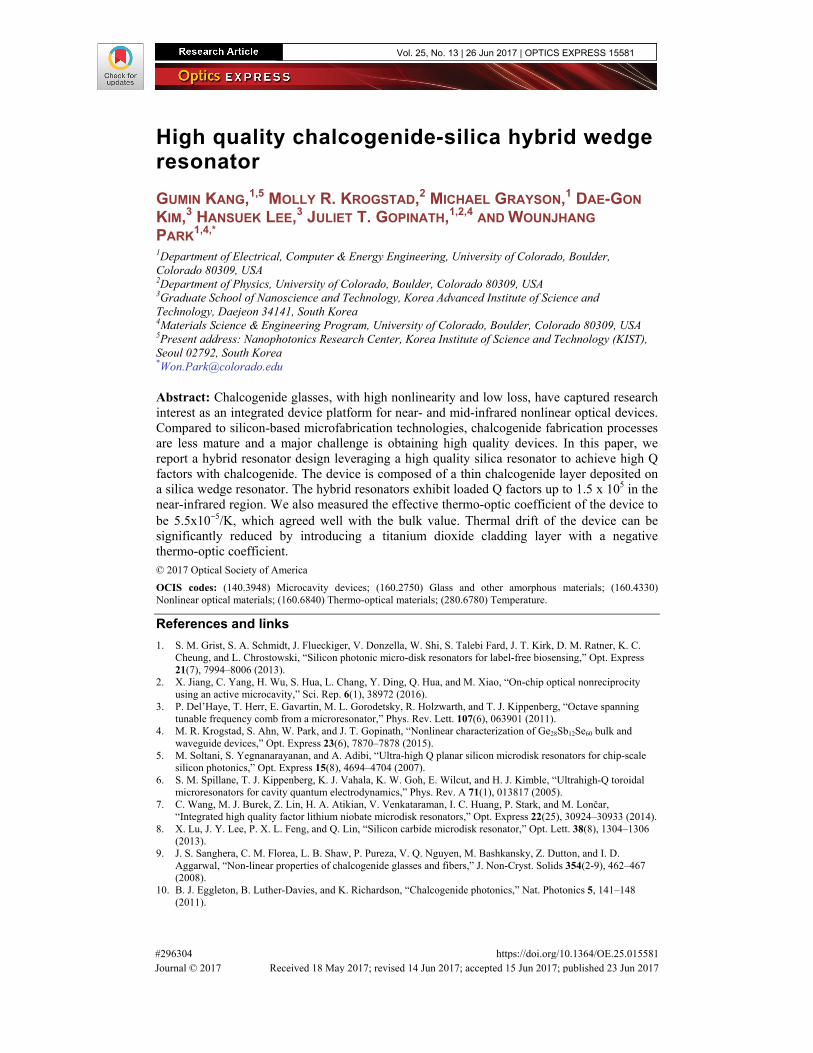
Figure 2(b) shows a scanning electron micrograph (SEM) of a fabricated chalcogenide-silica hybrid resonator, with a diameter of 46.5 um and a chalcogenide glass thickness of 125
nm. The chalcogenide glass thin film (Ge28Sb12Se60) evaporated on top of the silica wedge is clearly visible in the cross-sectional SEM image [Fig. 2(b)].
(a) (b)
ChG
SiO2ChG
Si
SiO2
Fig. 2. (a) Tilted scanning electron micrographs (SEMs) of chalcogenide glass-silica hybrid resonators [inset of (a) shows schematic cross section of hybrid resonators and white box indicates the imaged position of resonator in (b)]. (b) SEM image of cleaved cross-section of the hybrid resonator composed of thin Ge28Sb12Se60 film and SiO2 wedge. The inset shows a magnified false color SEM image of the disk edge.
2.2 Measurement setup
To characterize the microdisk resonators, a tunable laser with sub-MHz linewidth (Yenista TUNICS, 1500 nm ~1630 nm) is launched into a tapered silica fiber. The fiber is placed very close to the microdisk, with a coupling gap of several hundred nanometers. The transmission is monitored as a function of wavelength using a swept-wavelength interferometer system (Yenista CT400). The polarization of the input light is controlled using polarization control paddles. Both the fiber and microdisk are mounted on 3-axis piezo-actuated stages with 20 nm resolution, and imaged from above, using a microscope.
3. Results and discussion
3.1 Measure transmission spectrum and identify the resonance
Figure 3(a) shows a transmission spectrum of the resonators with two different diameters of 13.5 μm and 46.5 μm. A Lorentzian fit to the transmission spectrum shows that the 13.5 μm diameter resonator has a resonance at 1560 nm with a linewidth of 0.33 nm, while the 46.5 μm diameter resonator has a resonance at 1510 nm with a linewidth of 0.01 nm. The loaded Q factor of the 13.5 μm diameter resonator is 4.8 x 10³ and the free spectral range (FSR) 29.9 nm. The loaded Q factor of the 46.5 μm diameter is 1.5 x 10⁵ and the FSR, 9.5 nm. The measured Q factors are the loaded Q factors which include the coupling effect. To calculate intrinsic Q, we must exclude the coupling effect. For the 13.5 μm resonator, we achieved critical coupling and can calculate the intrinsic Q, since it is simply twice the measured loaded Q. For the 46.5 μm resonator, we were under-coupled. We fit the data using the procedure in [20] and obtained the loss within the resonator, self-coupling coefficient and effective index. By setting the self-coupling coefficient to unity, we could extract the intrinsic Q. The calculate intrinsic Q factor for the 13.5 μm resonator is 9.6 x 10³ and for the 46.5 μm resonator, 1.6 x 10⁵.
The Q factor of whispering gallery mode is determined by several sources of loss, such as radiation, material absorption and scattering. The calculated radiative Q, Qrad, of a 13.5 μm diameter resonator is ~107 (COMSOL finite element simulations). As the diameter is increased from 13.5 μm to 46.5 μm, Q increases to ~1017.
where n is the refractive index of material, α is the absorption coefficient, and λ is the wavelength [21]. The linear attenuation of bulk Ge28Sb12Se60 and silica are 0.3 dB/cm and 2 dB/km, respectively, at 1550 nm [11,22,23], which corresponds to an absorption limited Q factor, Qmat, of 1.89 x 10⁶. Our measured Q factors are much smaller than both Qrad and Qmat, meaning that the Q factor is limited by the scattering loss from surface and edge of the resonators. It is noted that the two different resonators exhibit similar level of RMS edge roughness, 1.6 nm for the 13.5 μm diameter and 2.2 nm for the 46.5 μm diameter, which is measured by high resolution SEM [Fig. 3(b)]. However, the Q factor of the 46.5 μm diameter resonator (Qloaded = 1.5 x 10⁵) is an order of magnitude higher than that of the 13.5 μm diameter resonator (Qloaded = 4.8 x 10³).
D = 13.5 μm
D = 46.5 μm
(a) (b)
Q = 4.8 x 10³
Q = 1.5 x 10⁵
330 pm
10 pm
100 nm
100 nm
* RMS roughness : 1.6 nm
* RMS roughness : 2.2 nm(c) (d)
Fig. 3. Transmission (black dot) spectrum using a tunable laser and silica tapered fiber. A Lorentzian fit (red curve) of a fundamental mode observed in the hybrid microdisk resonators with diameters of (a) 13.5 μm and (c) 46.5 μm. The full width at half maximum (FWHM) of the 13.5 μm diameter resonator is 330 pm and the 46.5 μm diameter resonator is 10 pm. SEM images present edges of the resonators with diameters of (b) 13.5 μm and (d) 46.5 μm.
3.2 Simulation results
To investigate the effect of diameter on quality factor, the optical mode profile and confinement factor is computed by 2D axisymmetric eigenmode analysis using COMSOL. The confinement factor is defined by the fraction of intensity (|E|2) inside the ChG layer. Figure 4 shows the field profile for the fundamental TE mode, while the resonator structure is indicated by the white lines. Most of the field is confined in the ChG layer, as Ge28Sb12Se60 has a high refractive index compared to the silica. The calculated confinement factor of ChG for 13.5 μm diameter resonators is 0.67 and that of the 46.5 μm diameter is 0.66. In comparison with small resonator, the mode of the large resonator has less field overlap with the surrounding air. This leads to reduced surface scattering at the air-ChG interface. Moreover, as the size is increased, the optical field is shifted away from the rough edges
defined by the lithography, wet etching and ChG deposition. Since both resonators were fabricated by the same process, they are expected to exhibit similar roughness at the interface and edges. Thus, the main reason for the difference in Q is attributed to the mode shift that results in significantly reduced edge scattering loss in the 46.5 μm resonator compared to the 13.5 μm resonator. By increasing the size of the resonator, we can increase Q further. Optimization of fabrication process to reduce roughness with thermal annealing can provide additional enhancement.
D = 13.5 μm
5.5 6.0 6.5 7.0Radius (μm)
D = 46.5 μm
22.0 22.5 23.0 23.5Radius (μm)
SiO2
SiO2
Fig. 4. Simulated fundamental mode profile in the resonator with 13.5 μm (top) and 46.5 μm diameter (bottom), showing field confinement in chalcogenide glass. The white solid outline indicates the silica wedge and ChG film. The white dash lines represent the center of modes. As the diameter of resonator increases, the mode moves to the inside of the disk which leads to isolation of the mode from rough boundary.
3.3 Thermal characterization
The thermal characteristics of the hybrid wedge resonators were also characterized. Since it is difficult to heat the resonator itself, the resonator fabricated on a silicon substrate was attached to a thermoelectric heater to control the temperature of substrate and a thermistor was used to monitor the temperature. To predict temperature distribution on the hybrid wedge resonator, we built a 3D heat transfer model using COMSOL Multiphysics. In this model, a ChG-Silica wedge resonator is supported by silicon pillar and 550 µm-thick silicon substrate was embedded in air and the boundary condition for air was set as a constant room temperature. We calculated the equilibrium temperature at the edge of the ChG by setting the bottom side of the silicon substrate as a heater temperature. The simulation results show that the temperature difference between the ChG layer and the silicon substrate is negligible over the range of temperatures studied, from room temperature up to 40.5 °C.
Light was coupled to a 46.5 μm diameter wedge resonator, using a silica tapered fiber, and transmission spectra were recorded as a function of the substrate (or ChG layer) temperature. Figure 5 shows the temperature dependence of resonant wavelength. The resonant wavelength increases as the temperature is increased, as shown in Fig. 5(a). A plot of the corresponding shift in resonant wavelength as a function of temperature reveals a thermal resonant shift of 60.5 pm/°C, as shown in Fig. 5(b). In general, both the thermo-optic coefficient and thermal
expansion can give rise to a shift in resonant wavelength from heating. The resonant wavelength is given by
2 Rn
m
πλ = (2)
where λ is the resonant wavelength, R is the resonator radius, n is the effective refractive index and m is the mode number. The temperature-dependent wavelength shift is then expressed by following equation,
2d dn dR
R ndT m dT dT
λ π = +
(3)
(a) (b)
Fig. 5. (a) Transmission vs. wavelength for a resonant mode in the hybrid resonator with diameter of 46.5 μm, taken at various temperatures. (b) Red shift in resonant wavelength of optical mode as a function of temperature. A linear fit to the data yields dλ/dT of 60.5 pm/°C.
However, given the low thermal expansion coefficient of silica and the small thickness of chalcogenide layer in our resonator geometry, the contributions from thermal expansion of these materials are found to be negligible [24, 25]. Therefore, the temperature dependence of refractive index can be approximated as
2
dn m d
dT R dT
λπ
(4)
Using this equation and the results of the temperature-dependent measurements, we obtained a thermo-optic coefficient of the resonator, of (5.5 ± 0.35) x 10−5 /K. The thermo-optic coefficient of bulk Ge28Sb12Se60 is 7.44 x 10⁻⁵ /K and that of fused silica is ~1 x 10⁻⁵ /K [24,25]. To compare experiments with theory, we calculate the mode confinement in the resonator and effective thermo-optic coefficient, using COMSOL. The calculated thermo-optic coefficient is 5.8 x 10⁻⁵ /K, which is in excellent agreement with the measured value.
3.4 Athermal microresonator design
A potential problem of this hybrid wedge resonator is the temperature-dependent wavelength shift due to relatively large thermo-optic coefficient of Ge28Sb12Se60. Therefore, an athermal resonator design is beneficial and allows compensation of thermal fluctuations from the environment and laser power. Since both Ge28Sb12Se60 and fused silica have a positive thermo-optic coefficient, materials with a negative thermo-optic coefficient must be used to compensate. Some polymers such as PDMS, PMMA, and polystyrene have been used as a cladding layer to eliminate thermal effects [26, 27]. However, polymers have low thermal stability and suffer from poor thickness control. In contrast, inorganic titanium dioxide
(TiO2), which has a negative thermo-optic coefficient [28], is very stable at high temperatures and precision thickness control can be obtained with CMOS compatible technologies. Moreover, TiO2 has a relatively high refractive index of 2.45, which can pull the optical mode from ChG layer towards the TiO2 cladding layer, reducing the thermal shift significantly [29].
Table 1. Thermo-optic coefficient of bulk materials at 1550nm.
The Q factor and the optical mode profile of a 3-layer hybrid resonator with TiO2 cladding layer were simulated using COMSOL [Fig. 6(a)]. As the loss of TiO2 is slightly higher than silica [30], Qmat of the 3-layer resonator decreased slightly to 1.41 x 10⁶. The fractional intensities, Γ , of air, ChG, TiO2, and SiO2 are defined by the fraction of intensity (|E|2) inside the respective layers. The effective thermo-optic coefficient and temperature dependent resonance shift of the device can be obtained from the confinement factors and Eq. (4), taking also into account the bulk thermo-optic properties listed in Table 1 [31].
2 2
2 2
effair ChG TiO SiO
air ChG TiO SiO
dn dn dn dn dn
dT dT dT dT dT = Γ + Γ + Γ + Γ
(5)
Figure 6(b) shows the calculated thermal drift of the resonance wavelength for different TiO2 cladding thickness. The simulation results show that thermo-optic properties of the resonator can be effectively engineered by changing the thickness of TiO2 cladding layer. For the resonator without TiO2 cladding layer, thermal shift of the resonant wavelength is 5.4 x 10⁻² nm/K. As the TiO2 cladding layer thickness is increased, the thermal shift gradually decreases, reaching zero at the thickness of 135.06 nm. With a 135 nm TiO2 cladding layer, Γair, ΓChG, ΓTiO2, ΓSiO2 are 0.03, 0.5, 0.38, 0.09, respectively, and the thermal shift can be reduced to 1.7 x 10⁻⁴ nm/K. The result shows that with the addition of TiO2, the temperature insensitivity of the device can be improved by more than two orders of magnitude.
(a) (b)
22.0 22.5 23.521.5 23.0Radius (μm)
SiO2
Fig. 6. (a) Cross-sectional mode profile in the athermal 3-layer hybrid resonator, which shows the field is stretched out into the TiO2 cladding layer. (b) Thermal shift of the resonant wavelength for the device with different TiO2 thickness. As the TiO2 thickness is increased, thermal shift of the mode gradually decreases, reaching zero at TiO2 thickness of 135.06 nm as indicated by star point.
4. Conclusion
With long-wavelength transparency, high nonlinearity and low nonlinear loss, ChGs are ideally suited for integrated nonlinear optical devices operating in the near and mid-infrared regions. Despite the attractive material properties, the lack of mature fabrication technology
presents challenges to obtaining high quality integrated optical devices based on ChGs. In this paper, we report a simple hybrid resonator design composed of a thin ChG layer deposited on a silica wedge resonator. The well-developed etch recipes for silica enable an extremely smooth surface of a silica wedge. The ChG overlayer deposited on it naturally forms a smooth surface. The hybrid resonators exhibit loaded Q factors as high as 1.5 x 10⁵ in the near-infrared region. Numerical simulations verified that increasing the resonator diameter can reduce both surface and edge scattering loss by isolating resonant mode from rough interfaces. Furthermore, we have characterized the thermal shift of the resonant mode in the ChG-silica hybrid microresonator. The measured thermo-optic coefficient of the resonator is consistent with the effective thermo-optic coefficient calculated with bulk thermo-optic properties and mode confinement factors. It is also possible to realize an athermal device by adding a titanium dioxide cladding layer. The new hybrid resonator provides an efficient platform to build high Q microresonators based on ChGs and will be important for near and mid-infrared nonlinear optical devices.
Funding
DARPA SCOUT program (W911NF-15-1-0621); Air Force Office of Scientific Research (FA9550-15-1-0506); and Asian Office of Aerospace R and D (FA2386-16-1-4139).
Acknowledgments
The authors thank David Carlson and Dr. Scott Papp at NIST for providing access to the fiber taper apparatus and for their valuable advice and discussion on the measurements using tapered fiber.


![Solution-processing of thick chalcogenide- chalcogenide ...and electromigration can take place [10–13]. Consequently, physical properties including refractive index, absorption coefficient,](https://static.documents.pub/doc/80x56/5fc3bbe46bcd59459d31ec52/solution-processing-of-thick-chalcogenide-chalcogenide-and-electromigration.jpg)


