344
3 rd Edition / December 2008 High Rate Ultra Wideband PHY and MAC Standard ECMA-368

3rd Edition / December 2008
High Rate Ultra Wideband PHY and MAC Standard
ECMA-368

COPYRIGHT PROTECTED DOCUMENT
© Ecma International 2008

Ecma International Rue du Rhône 114 CH-1204 Geneva T/F: +41 22 849 6000/01 www.ecma-international.org
StandardECMA-3683rd Edition - December 2008
High Rate Ultra Wideband PHY and MAC Standard


Introduction
This International Standard specifies the ultra wideband (UWB) physical layer (PHY) and mediumaccess control (MAC) sublayer for a high-speed, short-range wireless network, utilizing all or part ofthe spectrum between 3 100 − 10 600 MHz supporting data rates of up to 480 Mb/s.
This standard divides the spectrum into 14 bands, each with a bandwidth of 528 MHz. The first 12bands are then grouped into four band groups consisting of three bands. The last two bands aregrouped into a fifth band group. A sixth band group is also defined within the spectrum of the first four,consistent with usage within worldwide regulatory regulations.
A MultiBand Orthogonal Frequency Division Modulation (MB-OFDM) scheme is used to transmitinformation. A total of 110 sub-carriers (100 data carriers and 10 guard carriers) are used per band. Inaddition, 12 pilot subcarriers allow for coherent detection. Frequency-domain spreading, time-domainspreading, and forward error correction (FEC) coding are provided for optimum performance under avariety of channel conditions.
The MAC sublayer is designed to enable mobility, such that a group of devices may continuecommunicating while merging or splitting from other groups of devices. To maximize flexibility, thefunctionality of this MAC is distributed among devices. These functions include distributed coordinationto avoid interference between different groups of devices by appropriate use of channels anddistributed medium reservations to ensure Quality of Service. The MAC sublayer provides prioritizedschemes for isochronous and asynchronous data transfer. To do this, a combination of Carrier SenseMultiple Access (CSMA) and Time Division Multiple Access (TDMA) is used. A Distributed ReservationProtocol (DRP) is used to reserve the medium for TDMA access for isochronous and other traffic. Fornetwork scalability, Prioritized Contention Access (PCA) is provided using a CSMA scheme. The MAChas policies that ensure equitable sharing of the bandwidth.
Taken together, the PHY and MAC specified in this Ecma standard are well-suited to high rate, zeroinfrastructure communications between a mixed population of portable and fixed electronic devices.
This International Standard is not intended to represent the regulatory requirements of any country orregion.
The 2nd edition adds the following for regulatory flexibility:
• An additional TFI code
• An additional Band Group
• Tone nulling for interfence avoidance
and
• relaxes the requirement for Band group 1
• relocates some assigned numbers to Ecma registeries on the website.
The 3rd edition adds an Information Element for Bluetooth.
This Ecma Standard has been adopted by the General Assembly of December 2008.


Table of contents
1 Scope 1
2 Conformance 1
3 Normative References 1
4 Terms and Definit ions 1
4.1 access category (AC) 14.2 beacon group 14.3 beacon per iod (BP) 14.4 beacon per iod star t t ime (BPST) 14.5 channel 14.6 data integr i ty 24.7 device 24.8 distr ibuted reservat ion protocol (DRP) 24.9 extended beacon group 24.10 f rame 24.11 frame protect ion 24.12 MAC Cl ient 24.13 MAC command data uni t (MCDU) 24.14 MAC protocol data uni t (MPDU) 24.15 MAC service data uni t (MSDU) 24.16 message integr i ty code (MIC) 24.17 neighbour 24.18 network al locat ion vector (NAV) 24.19 pr ior i t ized content ion access (PCA) 24.20 pseudo-random number generat ion 24.21 random number generator 34.22 reservat ion 34.23 reservat ion block 34.24 secure f rame 34.25 stream 34.26 superframe 34.27 symmetr ic key 34.28 t ransmission opportuni ty (TXOP) 34.29 TXOP holder 34.30 user pr ior i ty 3
5 Notational conventions 3
- i -

6 Abbreviations and acronyms 3
7 General description 7
7.1 PHY general descr ipt ion 77.2 MAC general descr ipt ion 7
7.2.1 General descr ipt ion of the archi tecture 77.2.2 Device address 87.2.3 Features assumed from the PHY 87.2.4 Overview of MAC service funct ional i ty 97.2.5 MUX sublayer 137.2.6 MAC pol ic ies 137.2.7 Test vectors 13
8 PHY layer part i t ioning 14
8.1 PHY funct ion 148.2 PLCP sublayer 148.3 PMD sublayer 148.4 PHY layer management ent i ty (PLME) 14
9 Description of signal 14
9.1 Mathemat ical f ramework 149.2 Tone-Nul l ing 16
10 PLCP sublayer 16
10.1 PPDU 1710.1.1 PSDU rate-dependent parameters 1910.1.2 Timing-related parameters 1910.1.3 Frame-related parameters 20
10.2 PLCP preamble 2010.2.1 Standard PLCP preamble 2110.2.2 Burst PLCP preamble 23
10.3 PLCP header 4510.3.1 PHY header 4510.3.2 Reed-Solomon outer code for the PLCP header 4910.3.3 Header check sequence 52
10.4 PSDU 5210.4.1 Pad bi ts 53
10.5 Data scrambler 5410.6 Tai l b i ts 5510.7 Convolut ional encoder 5510.8 Bi t inter leaving 5910.9 Conste l lat ion mapping 61
10.9.1 QPSK 6110.9.2 Dual-carr ier modulat ion (DCM) 62
10.10 OFDM modulat ion 64
- ii -
10.10.1 Implementat ion considerat ions 6810.10.2 Data subcarr iers 6810.10.3 Guard subcarr iers 7210.10.4 Pi lot subcarr iers 72
11 General requirements 74
11.1 Operat ing band frequencies 7411.1.1 Operat ing f requency range 7411.1.2 Band numbering 74
11.2 Channel izat ion 7511.3 PHY layer t iming 79
11.3.1 Inter f rame spacing 7911.3.2 Receive-to- t ransmit turnaround t ime 7911.3.3 Transmit- to-receive turnaround t ime 8011.3.4 Time between successive t ransmissions 8011.3.5 Band f requency switch t ime 80
12 Transmitter specif ications 80
12.1 Transmit PSD mask 8012.2 Transmit centre f requency to lerance 8112.3 Symbol c lock f requency to lerance 8112.4 Clock synchronizat ion 8112.5 Phase coherence 8112.6 Transmit power contro l 8112.7 Transmit ter constel lat ion error 82
13 Receiver specif ication 84
13.1 Receiver sensi t iv i ty 8413.2 Receiver CCA performance 8513.3 Link qual i ty indicator 8513.4 Receive Signal Strength Indicator 86
14 Ranging and location awareness 86
14.1 Ranging requirements 8614.2 Ranging reference signal 8614.3 PHY ranging resources 8614.4 PHY ranging operat ion 8614.5 Ranging cal ibrat ion constants 8714.6 Example range measurement ( in format ive) 87
15 PHY and MAC service access points ( informative) 88
15.1 Gener ic MIB management pr imi t ives 8915.1.1 XX-GET.request 9015.1.2 XX-GET.conf i rm 9015.1.3 XX-SET.request 91
- iii -

15.1.4 XX-SET.conf i rm 9115.2 PHY SAP inter face 92
15.2.1 Data t ransfer 9215.2.2 PHY transmission control 9315.2.3 PHY recept ion control 9515.2.4 PHY CCA contro l 98
15.3 PLME SAP inter face 9915.3.1 PHY reset 10115.3.2 PHY ranging t imer contro l 101
15.4 MAC sublayer management pr imi t ives 10315.5 MAC management informat ion base (MIB) 10315.6 MLME SAP inter face 103
15.6.1 Reset 10315.6.2 Scan 10415.6.3 Beacon transmission and recept ion 10615.6.4 IE management 11115.6.5 PTK establ ishment 11315.6.6 GTK sol ic i tat ion/d istr ibut ion 11615.6.7 Temporal key update 11915.6.8 Secur i ty v io lat ion report 12115.6.9 Pseudo-random funct ion (PRF) 12215.6.10 Appl icat ion-speci f ic IE (ASIE) management 12315.6.11 Mult icast address binding 12615.6.12 Link events 12915.6.13 Probe 13315.6.14 Hibernat ion and s leep cycle 13615.6.15 Higher layer synchronizat ion support 14115.6.16 Reservat ion management 14315.6.17 Connect ion conf igurat ion pr imit ives 15015.6.18 Range measurement 15115.6.19 Appl icat ion-speci f ic command management 153
15.7 MAC SAP inter face 15515.7.1 MAC-DATA.request 15715.7.2 MAC-DATA.indicat ion 15715.7.3 MAC-DATA.conf i rm 158
16 MAC frame formats 158
16.1 Frame format convent ions 15816.1.1 Figures 15816.1.2 Octet order 15916.1.3 Encoding 159
16.2 General MAC frame format 15916.2.1 Frame control 16016.2.2 DestAddr 162
- iv -

16.2.3 SrcAddr 16216.2.4 Sequence control 16216.2.5 Access in format ion 16216.2.6 Frame payload 16316.2.7 FCS 164
16.3 Beacon frames 16516.4 Control f rames 166
16.4.1 Immediate acknowledgement ( Imm-ACK) 16716.4.2 Block acknowledgement (B-ACK) 16716.4.3 Request to send (RTS) 16816.4.4 Clear to send (CTS) 16816.4.5 Unused DRP reservat ion announcement (UDA) 16816.4.6 Unused DRP reservat ion response (UDR) 16916.4.7 Appl icat ion-speci f ic 169
16.5 Command frames 16916.5.1 DRP reservat ion request 17016.5.2 DRP reservat ion response 17116.5.3 Probe 17116.5.4 Pairwise temporal key (PTK) 17116.5.5 Group temporal key (GTK) 17216.5.6 Range measurement 17316.5.7 Appl icat ion-speci f ic 175
16.6 Data f rames 17516.7 Aggregated data f rames 17516.8 Informat ion elements 176
16.8.1 Appl icat ion-speci f ic IE (ASIE) 17816.8.2 Appl icat ion-speci f ic probe IE 17816.8.3 Beacon per iod occupancy IE (BPOIE) 17816.8.4 BP switch IE 17916.8.5 Channel change IE 18016.8.6 Distr ibuted reservat ion protocol (DRP) IE 18016.8.7 DRP avai labi l i ty IE 18216.8.8 Hibernat ion anchor IE 18216.8.9 Hibernat ion mode IE 18316.8.10 Ident i f icat ion IE 18316.8.11 Link feedback IE 18516.8.12 MAC capabi l i t ies IE 18616.8.13 Master key ident i f ier (MKID) IE 18716.8.14 Mult icast address b inding (MAB) IE 18716.8.15 PCA avai labi l i ty IE 18816.8.16 PHY capabi l i t ies IE 18916.8.17 Probe IE 19116.8.18 Regulatory Domain IE 19116.8.19 Rel inquish request IE 192
- v -

16.8.20 Tone-nul l ing (TN) IE 19316.8.21 Traff ic indicat ion map (TIM) IE 194
17 MAC sublayer functional description 194
17.1 Frame processing 19517.1.1 Frame addresses 19517.1.2 Frame recept ion 19617.1.3 Frame transact ion 19617.1.4 Frame transfer 19717.1.5 Frame retry 19717.1.6 Inter- f rame space ( IFS) 19717.1.7 Dupl icate detect ion 19817.1.8 RTS/CTS use 19817.1.9 MAC header f ie lds 19917.1.10 Informat ion elements 202
17.2 Beacon per iod 20517.2.1 Beacon slot state 20617.2.2 BP length 20617.2.3 Beacon transmission and recept ion 20717.2.4 Beacon slot co l l is ion detect ion 20817.2.5 BP contract ion 20917.2.6 Merger of mult ip le BPs 210
17.3 Pr ior i t ized content ion access (PCA) 21317.3.1 PCA medium avai labi l i ty 21417.3.2 NAV 21417.3.3 Medium status 21417.3.4 PCA parameters 21417.3.5 Obtaining a TXOP 21517.3.6 Using a TXOP 21617.3.7 Invoking a backoff procedure 21717.3.8 Decrement ing a backoff counter 219
17.4 Distr ibuted reservat ion protocol (DRP) 21917.4.1 Reservat ion type 21917.4.2 Medium access 22117.4.3 DRP avai labi l i ty IE 22117.4.4 DRP reservat ion negot iat ion 22117.4.5 DRP reservat ion announcements 22317.4.6 Resolut ion of DRP reservat ion conf l ic ts 22317.4.7 BPST real ignment and exist ing DRP reservat ions 22517.4.8 Modif icat ion and terminat ion of exist ing DRP reservat ions 22517.4.9 Release of hard or pr ivate DRP reservat ion b locks 22617.4.10 Retransmit procedures in DRP reservat ions 226
17.5 Synchronizat ion of devices 22717.5.1 Clock accuracy 227
- vi -

17.5.2 Synchronizat ion for devices in h ibernat ion mode 22717.5.3 Guard t imes 227
17.6 Fragmentat ion and reassembly 22917.7 Aggregat ion 23017.8 Acknowledgement pol ic ies 230
17.8.1 No-ACK 23017.8.2 Immediate ACK 23017.8.3 Block ACK 230
17.9 Probe 23217.10 Dynamic channel select ion 23317.11 Mult i - rate support 23317.12 Transmit power control 23317.13 Power management mechanisms 234
17.13.1 Power management modes 23417.13.2 Device power states 23417.13.3 Power state t ransi t ions 23417.13.4 Hibernat ion mode operat ion 23517.13.5 Hibernat ion anchor operat ion 236
17.14 ASIE operat ion 23717.15 Range measurement operat ion 23717.16 MAC sublayer parameters 240
18 Security 241
18.1 Secur i ty mechanisms 24218.1.1 Secur i ty operat ion 24218.1.2 4-way handshake 24218.1.3 Key t ransport 24218.1.4 Freshness protect ion 24318.1.5 Data encrypt ion 24318.1.6 Frame integr i ty protect ion 243
18.2 Secur i ty modes 24318.2.1 Secur i ty mode 0 24518.2.2 Secur i ty mode 1 24518.2.3 Secur i ty mode 2 245
18.3 Temporal keys 24618.3.1 Mutual authent icat ion and PTK der ivat ion 24618.3.2 GTK exchange 24718.3.3 Pseudo-random funct ion (PRF) def in i t ion 24818.3.4 PTK and KCK der ivat ion 24918.3.5 PTK MIC generat ion 25018.3.6 Random number generat ion 250
18.4 Frame recept ion steps and replay prevent ion measures 25018.4.1 Frame recept ion 25118.4.2 Replay prevent ion 251
- vii -
18.4.3 Impl icat ions on GTKs 25118.5 AES-128 CCM Inputs 251
18.5.1 Overview 25218.5.2 Nonce 25218.5.3 CCM blocks 252
Annex A (normative) MUX sublayer 255
Annex B (normative) MAC policies 259
Annex C (normative) Specif ier ID Assigned numbers 263
Annex D ( informative) MAC test vectors 265
Annex E ( informative) Example encoding of a PHY packet 277
Annex F ( informative) Recommended out-of-band emission l imits 323
Annex G ( informative) Range measurement calculations 325
Annex H ( informative) Bibl iography 329
- viii -

1 Scope
This International Standard specifies a distributed medium access control (MAC) sublayer and aphysical layer (PHY) for wireless networks.
2 Conformance
Conforming devices implement the MAC sublayer and the PHY layer as specified herein andsupport:
1. Data rates of 53,3 Mb/s, 106,7 Mb/s, and 200 Mb/s for transmitting and receiving;
2. At least one of the band groups;
3. Time-frequency codes using TFI, TFI2 and FFI.
In addition, conforming devices may implement the MAC/PHY Interface as specified in ECMA-369.
3 Normative References
The following referenced documents are indispensable for the application of this document. Fordated references, only the edition cited applies. For undated references, the latest edition of thereferenced document (including any amendments) applies.
ECMA-369, MAC-PHY Interface for ECMA-368
ISO/IEC 10646:2003, Information technology -- Universal Multiple-Octet Coded Character Set(UCS)
ISO/IEC 18033-3:2005, Information technology -- Security techniques -- Encryption algorithms -- Part 3: Block ciphers
4 Terms and Definitions
For the purposes of this International Standard, the following terms and definitions apply. Forterms not defined in this Clause, please consult IEEE100, The Authoritative Dictionary of IEEEStandards Terms, Seventh Edition.
4.1 access category (AC)label for the common set of prioritized contention access (PCA) parameters that are used bya device to contend for the medium in order to transmit MAC protocol data units (MPDUs)with certain priorities
4.2 beacon groupset of devices from which a device receives beacons that identify the same beacon periodstart time (BPST) as the device
4.3 beacon period (BP)period of time declared by a device during which it sends or listens for beacons
4.4 beacon period start time (BPST)start of the beacon period
4.5 channelmedium over which cooperating entities exchange information
- 1 -

4.6 data integrityassurance that the data has not been modified from its original form
4.7 deviceentity containing an implementation of this Standard
4.8 distributed reservation protocol (DRP)protocol implemented in each device to support negotiation and maintenance of channel timereservations binding on all neighbours of the reservation participants
4.9 extended beacon groupunion of a device's beacon group and the beacon groups of all devices in the device's beacongroup
4.10 frameunit of data transmitted by a device
4.11 frame protectionsecurity service provided for a frame, including (but not limited to) payload encryption,message authentication, and replay attack protection
4.12 MAC Cliententity above the MAC sublayer that generates MAC service data units for delivery tocorresponding entities in other devices, and receives MAC service data units from suchentities
4.13 MAC command data unit (MCDU)unit of data exchanged between peer medium access control sublayers in order to managemedium access control functions
4.14 MAC protocol data unit (MPDU)unit of data exchanged between two peer medium access control sublayers using thephysical layer
4.15 MAC service data unit (MSDU)information that is delivered as a unit between medium access control service access points(SAPs)
4.16 message integrity code (MIC)cryptographic checksum generated using a symmetric key that is typically appended to datain order to provide data integrity and source authentication similar to a digital signature
4.17 neighbourany device in a device's beacon group
4.18 network allocation vector (NAV)indicator, maintained by each device capable of using PCA, of time periods when PCA-basedtransmission onto the wireless medium will not be initiated by the device, whether or not thedevice's clear-channel assessment function senses that the wireless medium is busy
4.19 prioritized contention access (PCA)prioritized CSMA/CA access mechanism used by devices for medium access
4.20 pseudo-random number generationprocess of generating a deterministic sequence of bits from a given seed that has thestatistical properties of a random sequence of bits when the seed is not known
- 2 -

4.21 random number generatormethod or design that provides a sequence of bits that is unpredictable. A cryptographicrandom number generator is one specific type
4.22 reservationnamed set of one or more medium access slots (MASs) within a superframe during which adevice has preferential access to the medium
4.23 reservation blockone or more temporally contiguous medium access slots (MASs) within a reservation notadjacent to other MASs in the reservation
4.24 secure frameframe in which frame protection is applied
4.25 streamlogical flow of MSDUs from one device to one or more other devices
4.26 superframeperiodic time interval used in this Standard to coordinate frame transmissions betweendevices, which contains a beacon period followed by a data period
4.27 symmetric keysecret key shared between two or more parties that may be used for both encryption anddecryption as well as for message integrity code computation and verification
4.28 transmission opportunity (TXOP)interval of time obtained by a device using prioritized contention access (PCA) to initiatetransmissions onto the medium
4.29 TXOP holderdevice that has successfully contended for a TXOP
4.30 user priorityvalue assigned to an MSDU by the MAC client that determines the MSDU's transfer priority
5 Notational conventions
The use of the word shall is meant to indicate a requirement which is mandated by theStandard, i.e. it is required to support that particular feature with no deviation in order toconform to the Standard.
The use of the word should is meant to recommend one particular course of action over severalother possibilities, however without mentioning or excluding these others.
The use of the word may is meant to indicate that a particular course of action is permitted.
The use of the word can is synonymous with is able to – it is meant to indicate a capability or apossibility.
All floating-point values have been rounded to 4 decimal places.
6 Abbreviations and acronyms
AC Access Category
ACK Acknowledgment
- 3 -

AES Advanced Encryption Standard
AIFS Arbitration Inter-Frame Space
ASIE Application-Specific Information Element
B-ACK Block Acknowledgment
BcstAddr Broadcast Device Address
BM Burst Mode
BP Beacon Period
BPOIE Beacon Period Occupancy Information Element
BPST Beacon Period Start Time
CBC-MAC Cipher Block Chaining-Message Authentication Code
CCA Clear Channel Assessment
CCM Counter Mode Encryption and Cipher Block Chaining Message Authentication Code
CPE Common Phase Error
CRC Cyclic Redundancy Check
CSMA/CA Carrier Sense Multiple Access with Collision Avoidance
CTS Clear To Send
DAA Detect And Avoid
DAC Digital-to-Analog Converter
DCM Dual Carrier Modulation
DestAddr Destination Device Address
DevAddr Device Address
DME Device Management Entity
DRP Distributed Reservation Protocol
EO Encryption Offset
EUI Extended Unique Identifier
FCS Frame Check Sequence
FDS Frequency-Domain Spreading
FEC Forward Error Correction
FER Frame Error Rate
FFI Fixed-Frequency Interleaving
FFT Fast Fourier Transform
GF Galois Field
GTK Group Temporal Key
HCS Header Check Sequence
ID Identifier
IDFT Inverse Discrete Fourier Transform
- 4 -

IE Information Element
IFFT Inverse Fast Fourier Transform
IFS Inter-Frame Space
Imm-ACK Immediate Acknowledgment
KCK Key Confirmation Key
LQE Link Quality Estimator
LQI Link Quality Indicator
LSB Least-Significant Bit
MAC Medium Access Control
MAS Medium Access Slot
MCDU MAC Command Data Unit
McstAddr Multicast Device Address
MIB Management Information Base
MIC Message Integrity Code
MIFS Minimum Interframe Spacing
MKID Master Key Identifier
MLME MAC Sublayer Management Entity
MPDU MAC Protocol Data Unit
MSB Most-Significant Bit
MSDU MAC Service Data Unit
NAV Network Allocation Vector
No-ACK No Acknowledgement
OFDM Orthogonal Frequency Division Multiplexing
OUI Organizationally Unique Identifier
PAL Protocol Adaptation Layer
PAN Personal Area Network
PCA Prioritized Contention Access
PDU Protocol Data Unit
PER Packet Error Rate
PHY Physical (layer)
PHY-SAP Physical Layer Service Access Point
PLCP Physical Layer Convergence Protocol
PLME Physical Layer Management Entity
PMD Physical Medium Dependent
PMD-SAP Physical Medium Dependent-Service Access Point
PMK Pair-wise Master Key
PPDU PLCP Protocol Data Unit
- 5 -

PPM Parts Per Million
PRBS Pseudo-Random Binary Sequence
PRF Pseudo-Random Function
PSD Power Spectral Density
PSDU PHY Service Data Unit
PT Preamble Type
PTK Pair-wise Temporal Key
QPSK Quadrature Phase Shift Keying
RF Radio Frequency
RMS Root mean squared
RX Receive or Receiver
RS Reed-Solomon
RSSI Received Signal Strength Indicator
RTS Request To Send
SAP Service Access Point
SFC Secure Frame Counter
SFN Secure Frame Number
SIFS Short Interframe Spacing
SrcAddr Source Device Address
TDS Time-Domain Spreading
TF Time-Frequency
TFC Time-Frequency Code
TFI Time-Frequency Interleaving
TFI2 Time-Frequency Interleaving over 2 bands
TKID Temporal Key Identifier
TN Tone-Nulling
TPC Transmit Power Control
TX Transmit or Transmitter
TXOP Transmission Opportunity
UDA Unused DRP Reservation Announcement
UDR Unused DRP Reservation Response
UWB Ultra Wideband
ZPS Zero Padded Suffix
- 6 -

7 General description
7.1 PHY general descriptionThis Ecma Standard specifies the ultra wideband (UWB) physical layer (PHY) for a wirelesspersonal area network (PAN), utilizing the unlicensed 3 100 − 10 600 MHz frequency band,supporting data rates of 53,3 Mb/s, 80 Mb/s, 106,7 Mb/s, 160 Mb/s, 200 Mb/s, 320 Mb/s,400 Mb/s, and 480 Mb/s. Support for transmitting and receiving data rates of 53.3, 106.7, and200 Mb/s shall be mandatory.
The UWB spectrum is divided into 14 bands, each with a bandwidth of 528 MHz. The first 12bands are then grouped into 4 band groups consisting of 3 bands. The last two bands aregrouped into a fifth band group. A sixth band group is also defined within the spectrum of thefirst four, consistent with usage within worldwide spectrum regulations. At least one of theband groups shall be supported.
This Ecma Standard specifies a MultiBand Orthogonal Frequency Division Modulation (MB-OFDM) scheme to transmit information. A total of 110 sub-carriers (100 data carriers and 10guard carriers) are used per band to transmit the information. In addition, 12 pilot subcarriersallow for coherent detection. Frequency-domain spreading, time-domain spreading, andforward error correction (FEC) coding are used to vary the data rates. The FEC used is aconvolutional code with coding rates of 1/3, 1/2, 5/8 and 3/4.
The coded data is then spread using a time-frequency code (TFC). This Ecma Standardspecifies three types of time-frequency codes (TFCs): one where the coded information isinterleaved over three bands, referred to as Time-Frequency Interleaving (TFI); one wherethe coded information is interleaved over two bands, referred to as two-band TFI or TFI2; andone where the coded information is transmitted on a single band, referred to as FixedFrequency Interleaving (FFI). Support for TFI, TFI2 and FFI shall be mandatory.
Within the first four and the sixth band groups, four time-frequency codes using TFI and threetime-frequency codes using each of TFI2 and FFI are defined; thereby, providing support forup to ten channels in each band group. For the fifth band group, two time-frequency codesusing FFI and one using TFI2 are defined. For the sixth band group, the FFI channels andone of the TFI2 channels overlap fully with channels in the third and fourth band groups.
A mechanism is provided to allow individual OFDM subcarriers to be nulled. This, togetherwith the choice of frequency bands and of TFI, TFI2 and FFI time frequency codes, providessubstantial control over the use of spectrum by the transmitted signal, allowing the PHY to beused in a range of regulatory and radio coexistence scenarios.
7.2 MAC general description7.2.1 General description of the architecture
As illustrated in Figure 1, the MAC is a sublayer of the Data Link Layer defined in the OSIbasic reference model [H3]. The MAC service is provided by means of the MAC serviceaccess point (MAC SAP) to a single MAC service client, usually a higher layer protocol oradaptation layer. In this Standard the MAC sublayer is represented by a device address.
- 7 -
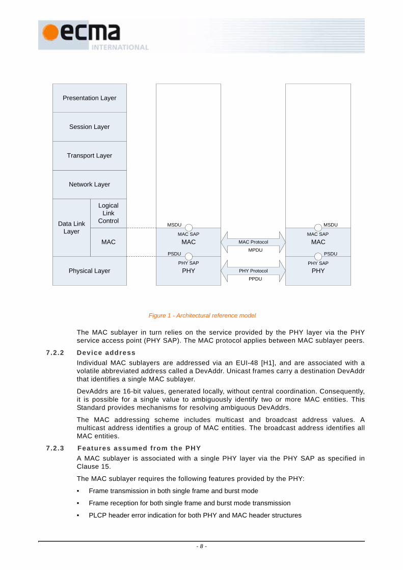
The MAC sublayer in turn relies on the service provided by the PHY layer via the PHYservice access point (PHY SAP). The MAC protocol applies between MAC sublayer peers.
7.2.2 Device addressIndividual MAC sublayers are addressed via an EUI-48 [H1], and are associated with avolatile abbreviated address called a DevAddr. Unicast frames carry a destination DevAddrthat identifies a single MAC sublayer.
DevAddrs are 16-bit values, generated locally, without central coordination. Consequently,it is possible for a single value to ambiguously identify two or more MAC entities. ThisStandard provides mechanisms for resolving ambiguous DevAddrs.
The MAC addressing scheme includes multicast and broadcast address values. Amulticast address identifies a group of MAC entities. The broadcast address identifies allMAC entities.
7.2.3 Features assumed from the PHYA MAC sublayer is associated with a single PHY layer via the PHY SAP as specified inClause 15.
The MAC sublayer requires the following features provided by the PHY:
• Frame transmission in both single frame and burst mode
• Frame reception for both single frame and burst mode transmission
• PLCP header error indication for both PHY and MAC header structures
Figure 1 - Architectural reference model
Physical Layer
MAC
PHY
Logical Link
Control
Network Layer
Transport Layer
Session Layer
Presentation Layer
MAC
Data Link Layer
PHY
MACMAC SAP MAC SAP
MAC Protocol
PHY ProtocolPHY SAP PHY SAP
MSDU
PSDU
MSDU
PSDUMPDU
PPDU
- 8 -

• Clear channel assessment for estimation of medium activity
• Range measurement timestamps if MAC range measurement is supported.
Figure 2 defines the structure of a PHY frame.
• There are two types of preamble: Standard and burst.
• The PLCP header including MAC and PHY Headers is protected by a header checksequence (HCS).
• The Frame Payload is followed by its frame check sequence (FCS).
Frames are transmitted by the PHY from the source device and delivered to the destinationdevice in identical bit order. The start of a frame refers to the leading edge of the firstsymbol of the PHY frame at the local antenna and the end of a frame refers to the trailingedge of the last symbol of the PHY frame.
Frame transmission and reception are supported by the exchange of parameters betweenthe MAC sublayer and the PHY layer. These parameters allow the MAC sublayer tocontrol, and be informed of, the frame transmission mode, the frame payload data rate andlength, the frame preamble, the PHY channel and other PHY-related parameters.
In single frame transmission, the MAC sublayer has full control of frame timing. In burstmode transmission, the MAC sublayer has control of the first frame timing and the PHYprovides accurate timing for the remaining frames in the burst.
7.2.4 Overview of MAC service functionalityThe MAC service defined in this Standard provides:
• Communication between cooperating devices within radio range on a single channel usingthe PHY;
• A distributed, reservation-based channel access mechanism;
• A prioritized, contention-based channel access mechanism;
• A synchronization facility for coordinated applications;
• Mechanisms for handling mobility and interference situations;
• Device power management by scheduling of frame transmission and reception;
• Secure communication with data authentication and encryption using cryptographicalgorithms;
• A mechanism for measuring the distance between two devices.
The architecture of this MAC service is fully distributed. All devices provide all requiredMAC functions and optional functions as determined by the application. No device acts asa central coordinator.
Coordination of devices within radio range is achieved by the exchange of beacon frames.Periodic beacon transmission enables device discovery, supports dynamic networkorganization, and provides support for mobility. Beacons provide the basic timing for thenetwork and carry reservation and scheduling information for accessing the medium.
Figure 2 - PHY Frame Structure
Preamble Frame Payload Frame Check SequencePLCP Header
PHY Header
MAC Header
Tail Bits
Tail BitsHCS Tail
BitsReed-Solomon
Parity Bytes
Tail Bits
Pad Bits
- 9 -

7.2.4.1 Logical groupsThe MAC protocol is specified with respect to an individual device, which has its ownindividual neighbourhood. All MAC protocol facilities are expressed with respect to thisindividual neighbourhood.
In a network formed with fully distributed medium access coordination, logical groupsare formed around each device to facilitate contention-free frame exchanges whileexploring medium reuse over different spatial regions. In this Standard, these logicalgroups are a beacon group and an extended beacon group, both of which aredetermined with respect to an individual device.
7.2.4.2 Control algorithmsMAC protocol algorithms attempt to ensure that no member of the extended beacongroup transmits a beacon frame at the same time as the device. Information included inbeacon frames facilitates contention-free frame exchanges by ensuring that a devicedoes not transmit frames while a neighbour is transmitting or receiving frames.
To permit correct frame reception, MAC protocol algorithms attempt to ensure that adevice's DevAddr is unique within the device's extended beacon group.
7.2.4.3 Channel select ionWhen a device is enabled, it scans one or more channels for beacons and selects achannel. If no beacons are detected in the selected channel, the device creates itsbeacon period (BP) by sending a beacon.
If one or more beacons are detected in the selected channel, the device synchronizes itsBP to existing beacons in the selected channel. The device exchanges data withmembers of its beacon group using the same channel the device selected for beacons.
Each device operates in a dynamic environment and under unlicensed operation rules.Thus, it is subject to interference from licensed users, other networks, and otherunlicensed wireless entities in its channel. To enable the device to continue operation inthis type of environment, each device has the capability to dynamically change thechannel in which it operates without requiring disruption of links with its peers.
If at any time a device determines that the current channel is unsuitable, it uses thedynamic channel selection procedure, as described in 17.10, to move to a new channel.
7.2.4.4 Beacon period protectionEach device protects its and its neighbours' BPs for exclusive use of the beaconprotocol. No transmissions other than beacons are attempted during the BP of anydevice. Protection of the device's BP is implicit.
A device may protect an alien BP, detected by reception of a beacon frame unalignedwith the device's own BP, by announcing a reservation covering the alien BP in itsbeacon.
7.2.4.5 The superframeThe basic timing structure for frame exchange is a superframe. The superframe durationis specified as mSuperframeLength. The superframe is composed of 256 mediumaccess slots (MASs), where each MAS duration is mMASLength.
Each superframe starts with a BP, which extends over one or more contiguous MASs.The start of the first MAS in the BP, and the superframe, is called the beacon period starttime (BPST).
- 10 -

7.2.4.6 Medium accessThe medium is accessed in one of three ways:
• During the BP, devices send only beacon frames, according to the rules specified in 17.2.
• During reservations, devices participating in the reservation send frames according torules specified in 17.4.
• Outside the BP and reservations, devices may send frames using a prioritized contention-based access method, as described in 17.3.
7.2.4.7 Data communication between devicesData is passed between the MAC sublayer and its client in MSDUs qualified by certainparameters. MSDUs are transported between devices in data frames. To reduce theframe error rate of a marginal link, data frames can be fragmented and reassembled, asdescribed in 17.6. Fragments are numbered with an MSDU sequence number and afragment number.
If the source device wishes to verify the delivery of a frame, then one of theacknowledgement policies is used, as described in 17.8. This Standard provides forthree types of acknowledgements to enable different applications. The No-ACK policy,described in 17.8.1, is appropriate for frames that do not require guaranteed delivery, orare delay sensitive and a retransmitted frame would arrive too late. The Imm-ACK policy,described in 17.8.2, provides an acknowledgement process in which each frame isindividually acknowledged following the reception of the frame. The B-ACK policy,described in 17.8.3, lets the source send multiple frames without intervening ACKframes. Instead, the acknowledgements of the individual frames are grouped into asingle response frame that is sent when requested by the source device. The B-ACKprocess decreases the overhead of the Imm-ACK process while allowing the sourcedevice to verify the delivery of frames to the destination.
If the source device does not receive the requested acknowledgement, then it mayretransmit the frame, as described in 17.3.7 and 17.4.10 or it may discard the frame.The decision to retransmit or discard the frame depends on the type of data or commandthat is being sent, the number of times that the source device has attempted to send theframe, the length of time it has attempted to send the frame, and other implementation-dependent factors.
7.2.4.8 MAC frame data ratesMAC beacon frames are intended to be received and interpreted by all devices andhence their frame payloads are transmitted at pBeaconTransmitRate, which can be
Figure 3 - MAC superframe structure
Superframe N(256 Medium Access Slots = 65 536µs)
Time
Beacon Period (Variable Length)
...
Medium Access Slot (MAS) = 256µs
Superframe N+1
Start timing of Superframe N Start timing of Superframe N+1
Beacon Period (Variable Length)
BPST (Time = 0)
- 11 -

decoded by all recipients. Other frames are exchanged in a more restricted context andtheir frame payloads may be transmitted at higher data rates if possible. Frame headersare always transmitted at the lowest data rate supported by the PHY.
7.2.4.9 SecurityWireless networks present unique security challenges due to the loss of protectionprovided by wires and shielding. Distributed wireless networks present additionalchallenges due to the wide range of applications and use models that they must support.To name a few, eavesdroppers can overhear data exchanges not intended for them,whereas imposters can send forged data not using its own identity, can replay previouslytransmitted data, and can transmit modified data captured from a previous transmission.
This Standard (Clause 18) defines two levels of security: no security and strong securityprotection. Security protection includes data encryption, message integrity, and replayattack protection. Secure frames are used to provide security protection to data andaggregated data frames as well as selected control and command frames.
Three security modes are defined to control the level of security for devices in theircommunications. This Standard allows for a device to use one of the two security levelsor a combination of them in communicating with other devices by selecting theappropriate security mode (18.2).
This Standard further specifies a 4-way handshake mechanism to enable two devices toderive their pair-wise temporal keys (PTKs) while authenticating their identity to eachother. A secure relationship is established following a successful 4-way handshakebetween two devices (18.3.1). A 4-way handshake between two devices is conductedbased on a shared master key. How two devices obtain their shared master keys isoutside the scope of this Standard.
In addition, this Standard provides means for the solicitation and distribution of grouptemporal keys (GTKs). While PTKs are used for protecting unicast frames exchangedbetween two devices, GTKs are employed for protecting multicast and broadcast framestransmitted from a source device to a multicast or broadcast group of recipient devices(18.3.2).
A pseudo-random function (18.3.3) is defined based on the message integrity code(MIC) generation by CCM using AES-128 that is defined in ISO/IEC 18033-3:2005. Itcan be made available to entities outside the MAC sublayer for random numbergeneration.
Secure frame counters and replay counters are set up on a per-temporal key basis toguarantee message freshness (18.4). No specific mechanisms are created in thisStandard to address denial of service attacks given the open nature of the wirelessmedium.
In this Standard, 128-bit symmetric temporal keys are employed based on AES-128 withCCM to provide payload encryption and message integrity code (MIC) generation (18.5).
In general, this Standard specifies security mechanisms, not security policies.
7.2.4.10 Information discoveryThe protocols and facilities of this Standard are supported by the exchange ofinformation between devices. Information can be broadcast in beacon frames orrequested in Probe commands. For each type of information, an Information Element(IE) is defined. IEs can be included by a device in its beacon at any time and mayoptionally be requested or provided using the Probe command.
A device uses the MAC Capabilities IE and PHY Capabilities IE to announce informationabout its support of variable or optional facilities. Declaration of capabilities is especiallyuseful when a device detects changes in its immediate neighbourhood.
- 12 -
7.2.4.11 Support for higher-layer t imer synchronizationSome applications, for example, the transport and rendering of audio or video streams,require synchronization of timers located at different devices. Greater accuracy (in termsof jitter bounds) or finer timer granularity than that provided by the synchronizationmechanism described in 17.5 may be an additional requirement. In support of suchapplications, this Standard defines an optional MAC facility that enables layers abovethe MAC sublayer to accurately synchronize timers located in different devices. Thefacility is usable by more than one application at a time.
7.2.4.12 Rate adaptat ionA mechanism for data rate adaptation is provided in 17.11. A receiver may use thismechanism to inform a transmitter of the optimal data rate to increase throughput and/orreduce the frame error rate (FER).
7.2.4.13 Power managementAn important goal of this Standard is to enable long operation time for battery powereddevices. An effective method to extend battery life is to enable devices to turn offcompletely or reduce power for long periods of time, where a long period is relative tothe superframe duration.
This Standard provides two power management modes in which a device can operate:active and hibernation. Devices in active mode transmit and receive beacons in everysuperframe. Devices in hibernation mode hibernate for multiple superframes and do nottransmit or receive in those superframes.
In addition, this Standard provides facilities to support devices that sleep for portions ofeach superframe in order to save power.
To coordinate with neighbours, a device indicates its intention to hibernate by including aHibernation Mode IE in its beacon. The Hibernation Mode IE specifies the number ofsuperframes in which the device will sleep and will not send or receive beacons or anyother frames.
Power management mechanisms are described in 17.13.
7.2.4.14 Range measurementA device may contain provisions to support one-dimensional ranging measurementsbetween devices using two-way time transfer techniques. This Standard describesmethods in the MAC sublayer to make range measurements in 17.15.
7.2.5 MUX sublayerIn order to enable the coexistence of concurrently active higher layer protocols within asingle device, a multiplexing sublayer is defined. This sublayer routes outgoing andincoming MSDUs to and from their corresponding higher layers. The mandatory MUXsublayer is described in Annex A.
7.2.6 MAC policiesIt is desirable to allow and facilitate equitable and efficient coexistence of devices withvarying medium access requirements. For this purpose, Annex B specifies policiesgoverning sharing of bandwidth. These policies impose, among other things, certainrestrictions on the number and configuration of MASs in DRP reservations, and on thelocation of reserved MASs within a superframe.
7.2.7 Test vectorsTo facilitate implementation and interoperability, Annex B provides examples of fieldencoding in MAC frames and the corresponding octet sequences passed to the PHY SAP.The examples include results from security operation and FCS calculation.
- 13 -

8 PHY layer partitioning
This Clause describes the PHY services provided to the MAC. The PHY layer consists of twoprotocol functions:
a. A PHY convergence function, which adapts the capabilities of the physical medium dependent(PMD) device to the PHY service. This function is supported by the physical layer convergenceprotocol (PLCP), which defines a method of mapping the PLCP service data units (PSDU) into aframing format suitable for sending and receiving user data and management informationbetween two or more stations using the associated PMD device.
b. A PMD device whose function defines the characteristics and method of transmitting andreceiving data through a wireless medium between two or more stations, each using the EcmaPHY.
8.1 PHY functionThe PHY contains three functional entities: the PMD function, the PHY convergence function,and the layer management function. The PHY service is provided to the MAC through thePHY service primitives.
8.2 PLCP sublayerIn order to allow the MAC to operate with minimum dependence on the PMD sublayer, thePHY convergence sublayer is defined. This function simplifies the PHY service interface tothe MAC services.
8.3 PMD sublayerThe PMD sublayer provides a means to send and receive data between two or more stations.
8.4 PHY layer management entity (PLME)The PLME performs management of the local PHY functions in conjunction with the MACmanagement entity.
9 Description of signal
9.1 Mathematical frameworkThe transmitted RF signal can be written in terms of the complex baseband signal as follows:
sRF(t) = Re sn(t − nTSYM)exp(j2πfc(q(n))t) , (1)
where Re(⋅) represents the real part of the signal, TSYM is the symbol length, Npacket is the
number of symbols in the packet, fc(m) is the centre frequency for the mth frequency band,
q(n) is a function that maps the nth symbol to the appropriate frequency band, and sn(t) is the
complex baseband signal representation for the nth symbol, which must satisfy the followingproperty: sn(t) = 0 for t ∉[0, TSYM). The exact structure of the nth symbol depends on itslocation within the packet:
n 0=
Npacket 1–
∑⎩⎪ ⎪⎨⎪ ⎪⎧
⎭⎪⎬⎪⎫
- 14 -

sn(t) = , (2)
where ssync,n(t) describes the nth symbol of the preamble, shdr,n(t) describes the nth symbol of
the header, sframe,n(t) describes the nth symbol of the PSDU, Nsync is the number of symbols inthe preamble, Nhdr is the number of symbols contained in the header, and Npacket = Nframe +Nsync + Nhdr is the number of symbols in the payload. The exact values of Nsync, Nhdr, Nframe,and Npacket will be described in more detail in Clause 10.
The potentially complex time-domain signal sn(t) shall be created by passing the real andimaginary components of the discrete-time signal sn[k] through digital-to-analog converters(DACs) and anti-alias filters as defined in Figure 4. When the discrete-time signal sn[k] isreal, only the real digital-to-analog converter and anti-aliasing filter need to be used. Clause10 describes how to generate sn[k].
Figure 5 shows one realization of the transmitted RF signal using three frequency bands,where the first symbol is transmitted on a centre frequency of 3 432 MHz, the second symbolis transmitted on a centre frequency of 3 960 MHz, the third symbol is transmitted on a centrefrequency of 4 488 MHz, the fourth symbol is transmitted on a centre frequency of 3 432MHz, and so on. In addition, it is apparent from Figure 5 that the symbol is created byappending a zero-padded suffix (ZPS) to the IFFT output, or equivalently, to the OFDMsymbol. The zero-padded suffix serves two purposes: it provides a mechanism to mitigate theeffects of multi-path; and, it provides a time window (a guard interval) to allow sufficient timefor the transmitter and receiver to switch between the different centre frequencies.
A symbol is defined as an OFDM symbol (IFFT output) plus a zero-padded suffix.
ssync n, t( ) 0 n Nsync<≤
shdr n Nsync–, t( ) Nsync n Nsync N+ hdr<≤
sframe n Nsync– Nhdr–, t( ) Nsync Nhdr+ n Npacket<≤⎩⎪⎪⎨⎪⎪⎧
DACRe{sn[k]} Re{sn(t)}Anti-
Aliasing Filter
DACIm{sn[k]} Im{sn(t)}Anti-
Aliasing Filter
Figure 4 - Conversion from discrete-time signals to continuous-time signals
- 15 -

9.2 Tone-NullingIn order to support avoidance of other users of the UWB band, the transmitted signal is sentin the context of a configured array TN of 384 tone-nulling elements. These correspond to thesubcarriers of each band within the current band group, so that TN[0 to 127] apply to thesubcarriers of the lowest frequency band in the current band group, TN[128 to 255] to themiddle band, and TN[256 to 383] to the highest band, if present. See 11.1.2 for a descriptionof bands and band groups.
Each tone-nulling element can take the value ONE or ZERO. If the value is ZERO, then thetransmitter should take steps to minimize the transmitted signal energy at the frequency ofthe corresponding subcarrier. If the value is ONE, then the signal is unaffected by tone-nulling. No specific reduction in energy for any tone null is specified in this document. Tone-nulling is an optional feature. Tone-nulling applies to all symbols, including the preamblesequence.
A device shall transmit at least 86 useful tones per band, where useful tones relate to tonescontaining data, pilot, the preamble or the channel estimation sequence. This limit preventsunacceptable degradation of packet detection performance, and other receive performance.If more tones in a band must be avoided, the entire band cannot be used for transmission.
A device may null additional tones beyond those specified, for instance to improve orpreserve symmetry within the transmitted symbols, subject to the constraint that at least 86useful tones shall be transmitted per band. If additional tones are nulled then this shall bedone consistently throughout the packet.
The simplest possible implementation is to set to zero the corresponding values of IFFTinputs, and to generate the sync symbols through the same IFFT process as other symbols.
10 PLCP sublayer
This Clause provides a method for converting a PSDU into a PPDU. During the transmission,the PSDU shall be pre-appended with a PLCP preamble and a PLCP header in order to createthe PPDU. At the receiver, the PLCP preamble and PLCP header serve as aids in thedemodulation, decoding, and delivery of the PSDU.
Figure 5 - Example realization of a transmitted RF signal using three bands
Time
Freq (MHz)
3168
3696
4752
4224
Band # 1
Band # 2
Band # 3
Zero-paddedSuffix
IFFT Output(OFDM Symbol)
Symbol
- 16 -

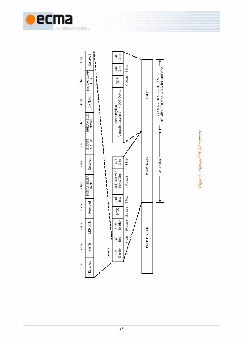
10.1 PPDUFigure 6 defines the format for the PPDU, which is composed of three components: the PLCPpreamble, the PLCP header, and the PSDU. The components are listed in the order oftransmission. The PLCP preamble is the first component of the PPDU and can be furtherdecomposed into a packet/frame synchronization sequence, and a channel estimationsequence (see 10.2). The goal of the PLCP preamble is to aid the receiver in timingsynchronization, carrier-offset recovery, and channel estimation.
The PLCP header is the second component of the PPDU. The goal of this component is toconvey necessary information about both the PHY and the MAC to aid in decoding of thePSDU at the receiver. The PLCP header can be further decomposed into a PHY header, MACheader, header check sequence (HCS), tail bits, and Reed-Solomon parity bits (see 10.3).Tail bits are added between the PHY header and MAC header, HCS and Reed-Solomonparity bits, and at the end of the PLCP header in order to return the convolutional encoder tothe “zero state”. The Reed-Solomon parity bits are added in order to improve the robustnessof the PLCP header.
The PSDU is the last component of the PPDU (see 10.4). This component is formed byconcatenating the frame payload with the frame check sequence (FCS), tail bits, and finallypad bits, which are inserted in order to align the data stream on the boundary of the symbolinterleaver.
When transmitting the packet, the PLCP preamble is sent first, followed by the PLCP header,and finally by the PSDU. The PLCP header is a codeword of a systematic Reed-Solomoncode, appended with tail bits as explained above. As defined in Figure 6, the systematic partof the PLCP header is always sent at a data rate of 39,4 Mb/s. The PSDU is sent at thedesired data rate of 53,3 Mb/s, 80 Mb/s, 106,7 Mb/s, 160 Mb/s, 200 Mb/s, 320 Mb/s,400 Mb/s or 480 Mb/s.
The least-significant bit (LSB) of an octet shall be the first bit transmitted.
- 17 -
Fig
ure
6 - S
tand
ard
PP
DU
stru
ctur
e
PHY
Hea
der
Tail
Bits
MA
CH
eade
rH
CS
Tail
Bits
Tail
Bits
Ree
d-So
lom
on
Parit
y Bi
tsTa
ilB
itsPa
dBi
tsFC
SFr
ame
Payl
oad
Var
iabl
e Le
ngth
: 0 –
409
5 O
ctet
s
PSD
UPL
CP H
eade
rPL
CP
Pre
ambl
e
39,4
Mb/
s53
,3 M
b/s,
80 M
b/s,
106,
7 M
b/s,
20
0 M
b/s,
320
Mb/
s, 40
0 M
b/s,
480
Mb/
s
5 oc
tets
6 bi
ts10
octe
ts2
octe
ts6
bits
6 oc
tets
4 bi
ts4
octe
ts6
bits
12 bi
ts5
bits
3 bi
ts2
bits
2 bi
ts8
bits
Rese
rved
RA
TELE
NG
THR
eser
ved
SCR
AMB
LER
INIT
Res
erve
dB
URS
TM
OD
EPR
EAM
BLE
TYPE
Res
erve
d
2 bi
ts1
bit
1 bi
t
TX T
FCB
AN
D G
RO
UP
LSB
3 bi
ts1
bit
- 18 -

10.1.1 PSDU rate-dependent parametersThe PSDU data rate-dependent modulation parameters are listed in Table 1.
10.1.2 Timing-related parametersThe timing parameters associated with the OFDM PHY are listed in Table 2.
Table 1 - PSDU rate-dependent Parameters
Data Rate (Mb/s) Modulation
Coding Rate (R)
FDS TDSCoded Bits /
6 OFDM Symbol (NCBP6S)
Info Bits / 6 OFDM Symbol
(NIBP6S)
53,3 QPSK 1/3 YES YES 300 100
80 QPSK 1/2 YES YES 300 150
106,7 QPSK 1/3 NO YES 600 200
160 QPSK 1/2 NO YES 600 300
200 QPSK 5/8 NO YES 600 375
320 DCM 1/2 NO NO 1 200 600
400 DCM 5/8 NO NO 1 200 750
480 DCM 3/4 NO NO 1 200 900
Table 2 - Timing-re lated Parameters
Parameter Description Value
fs Sampling frequency 528 MHz
NFFT Total number of subcarriers (FFT size) 128
ND Number of data subcarriers 100
NP Number of pilot subcarriers 12
NG Number of guard subcarriers 10
NT Total number of subcarriers used 122 (= ND + NP + NG)
Df Subcarrier frequency spacing 4,125 MHz (= fs ⁄ NFFT)
TFFT IFFT and FFT period 242,42 ns (Δf-1)
NZPS Number of samples in zero-padded suffix 37
TZPS Zero-padded suffix duration in time 70,08 ns (= NZPS ⁄ fs)TSYM Symbol interval 312,5 ns (= TFFT + TZPS)
FSYM Symbol rate 3,2 MHz (= TSYM-1)
NSYM Total number of samples per symbol 165 (= NFFT + NZPS)
- 19 -

10.1.3 Frame-related parametersThe frame parameters associated with the PHY are listed in Table 3, where ⎡⋅⎤ is the ceilingfunction, which returns the smallest integer value greater than or equal to its argument.
10.2 PLCP preambleA PLCP preamble shall be added prior to the PLCP header to aid the receiver in timingsynchronization, carrier-offset recovery, and channel estimation. In this Clause both aStandard PLCP preamble and a burst PLCP preamble are defined. A unique preamblesequence shall be assigned to each time-frequency code (TFC).
The preamble is defined to be a real baseband signal, which shall be inserted into the realportion of the complex baseband signal. Tone-nulling (see 9.2), if implemented, is theapplied. The PLCP preamble consists of two portions: a time-domain portion (packet ⁄ framesynchronization sequence) followed by a frequency-domain portion (channel estimationsequence).
In this Clause two preambles are defined: a Standard PLCP preamble and a burst PLCPpreamble. The burst preamble shall only be used in the burst mode when a burst of packetsis transmitted, separated by a minimum inter-frame separation time (pMIFS). For data ratesof 200 Mb/s and lower, all the packets in the burst shall use the Standard PLCP preamble.However, for data rates higher than 200 Mb/s, the first packet shall use the Standard PLCP
Table 3 - Frame-related Parameters
Parameter Description Value
Npf Number of symbols in the packet/frame synchronization sequence
Standard Preamble: 24Burst Preamble: 12
Tpf Duration of thepacket/frame synchronization sequence
Standard Preamble: 7,5 μsBurst Preamble: 3,75 μs
Nce Number of symbols in the channel estimation sequence
6
Tce Duration of thechannel estimation sequence
1,875 μs
Nsync Number of symbols in the PLCP preamble Standard Preamble: 30Burst Preamble: 18
Tsync Duration of the PLCP preamble Standard Preamble: 9,375 μsBurst Preamble: 5,625 μs
Nhdr Number of symbols in the PLCP header 12
Thdr Duration of the PLCP header 3,75 μs
Nframe Number of symbols in the PSDU
Tframe Duration for the PSDU
Npacket Total number of symbols in the packet Nsync+Nhdr+Nframe
Tpacket Duration of the packet (Nsync+Nhdr+Nframe) × TSYM
6 8 LENGTH 38+×NIBP6S
-----------------------------------------------×
6 8 LENGTH 38+×NIBP6S
----------------------------------------------- TSYM××
- 20 -

preamble, while the remaining packets may use either the Standard PLCP preamble or theburst PLCP preamble. Support for transmission and reception of burst PLCP preamble ismandatory for all supported data rates above 200Mbps. The preamble type (PT) bit in thePHY header (see 10.3.1.5) describes the type of preamble that shall be used in the nextpacket.
10.2.1 Standard PLCP preambleFigure 7 defines the structure of the Standard PLCP preamble. The preamble can be sub-divided into two distinct portions: a packet/frame synchronization sequence and a channelestimation sequence. The packet/frame synchronization sequence shall be constructed asdefined in Figure 8:
1. For a given time-frequency code, select the appropriate base time-domain sequencesbase[l] from Table 4 through Table 10 and the appropriate Standard cover sequencescover[m] from Table 21.
2. Form an extended time-domain sequence sext[l] by appending NZPS “zero samples” to thelength NFFT sequence sbase[l].
3. The kth sample of the nth symbol in the Standard preamble ssync,n[k], corresponding to thepacket/frame synchronization sequence, is given by:
ssync,n[k] = scover[n] × sext[k], (3)
where n ∈ [0, Npf − 1], k ∈ [0, NSYM − 1], Npf is defined in Table 3 and NSYM is defined inTable 2.
Figure 7 - Block diagram of the Standard PLCP preamble
Tsync = 9,375 μs, Nsync = 30
ssync,0[k] ssync,24[k]ssync,1[k] ssync,23[k] ssync,29[k]……
Packet/Frame Synchronization Sequence
Channel Estimation Sequence
- 21 -
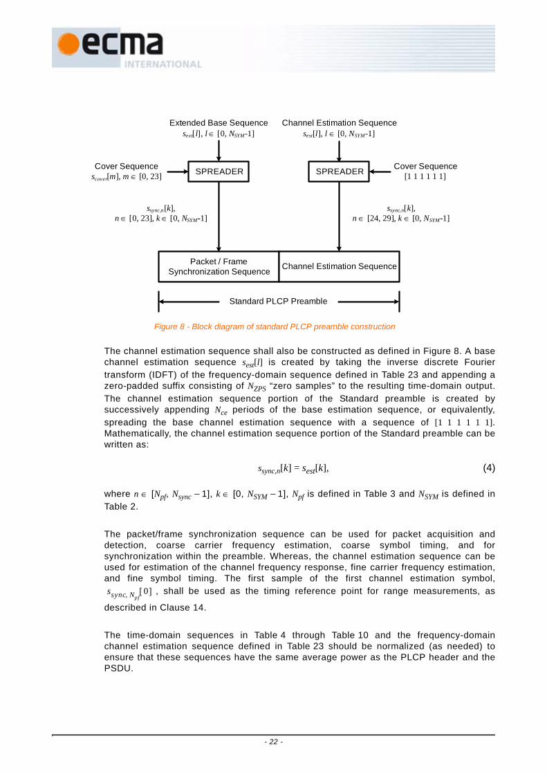
The channel estimation sequence shall also be constructed as defined in Figure 8. A basechannel estimation sequence sest[l] is created by taking the inverse discrete Fouriertransform (IDFT) of the frequency-domain sequence defined in Table 23 and appending azero-padded suffix consisting of NZPS “zero samples” to the resulting time-domain output.The channel estimation sequence portion of the Standard preamble is created bysuccessively appending Nce periods of the base estimation sequence, or equivalently,spreading the base channel estimation sequence with a sequence of [1 1 1 1 1 1].Mathematically, the channel estimation sequence portion of the Standard preamble can bewritten as:
ssync,n[k] = sest[k], (4)
where n ∈ [Npf, Nsync − 1], k ∈ [0, NSYM − 1], Npf is defined in Table 3 and NSYM is defined inTable 2.
The packet/frame synchronization sequence can be used for packet acquisition anddetection, coarse carrier frequency estimation, coarse symbol timing, and forsynchronization within the preamble. Whereas, the channel estimation sequence can beused for estimation of the channel frequency response, fine carrier frequency estimation,and fine symbol timing. The first sample of the first channel estimation symbol,
, shall be used as the timing reference point for range measurements, as
described in Clause 14.
The time-domain sequences in Table 4 through Table 10 and the frequency-domainchannel estimation sequence defined in Table 23 should be normalized (as needed) toensure that these sequences have the same average power as the PLCP header and thePSDU.
Extended Base Sequencesext[l], l ∈ [0, NSYM-1]
Cover Sequencescover[m], m ∈ [0, 23] SPREADER
Channel Estimation Sequencesest[l], l ∈ [0, NSYM-1]
Standard PLCP Preamble
Packet / FrameSynchronization Sequence Channel Estimation Sequence
ssync,n[k], n ∈ [0, 23], k ∈ [0, NSYM-1]
SPREADER Cover Sequence[1 1 1 1 1 1]
ssync,n[k], n ∈ [24, 29], k ∈ [0, NSYM-1]
Figure 8 - Block diagram of standard PLCP preamble construction
ssync Npf, 0[ ]
- 22 -
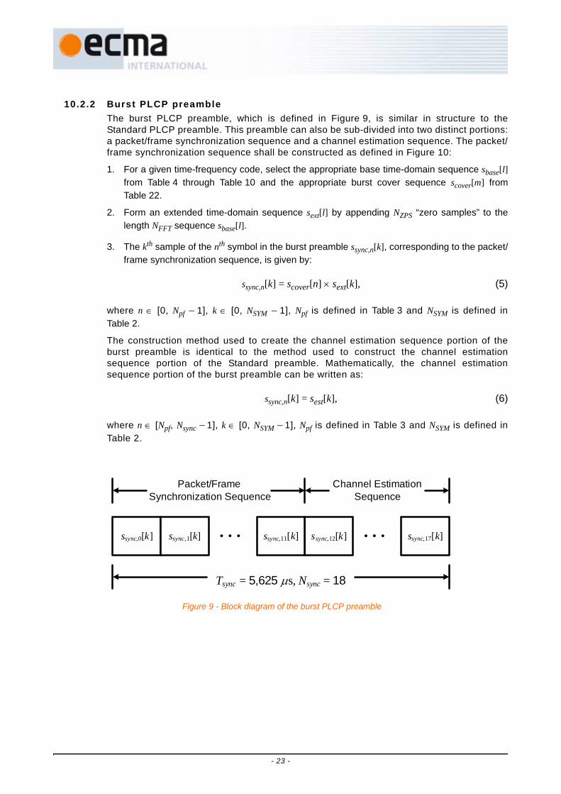
10.2.2 Burst PLCP preambleThe burst PLCP preamble, which is defined in Figure 9, is similar in structure to theStandard PLCP preamble. This preamble can also be sub-divided into two distinct portions:a packet/frame synchronization sequence and a channel estimation sequence. The packet/frame synchronization sequence shall be constructed as defined in Figure 10:
1. For a given time-frequency code, select the appropriate base time-domain sequence sbase[l]from Table 4 through Table 10 and the appropriate burst cover sequence scover[m] fromTable 22.
2. Form an extended time-domain sequence sext[l] by appending NZPS “zero samples” to thelength NFFT sequence sbase[l].
3. The kth sample of the nth symbol in the burst preamble ssync,n[k], corresponding to the packet/frame synchronization sequence, is given by:
ssync,n[k] = scover[n] × sext[k], (5)
where n ∈ [0, Npf − 1], k ∈ [0, NSYM − 1], Npf is defined in Table 3 and NSYM is defined inTable 2.
The construction method used to create the channel estimation sequence portion of theburst preamble is identical to the method used to construct the channel estimationsequence portion of the Standard preamble. Mathematically, the channel estimationsequence portion of the burst preamble can be written as:
ssync,n[k] = sest[k], (6)
where n ∈ [Npf, Nsync − 1], k ∈ [0, NSYM − 1], Npf is defined in Table 3 and NSYM is defined inTable 2.
Tsync = 5,625 μs, Nsync = 18
ssync,0[k] ssync,12[k]ssync,1[k] ssync,11[k] ssync,17[k]……
Packet/Frame Synchronization Sequence
Channel Estimation Sequence
Figure 9 - Block diagram of the burst PLCP preamble
- 23 -

The time-domain sequences for TF codes 1-7, defined in Table 4 through Table 10, havebeen spectrally flattened for a 4,125 MHz resolution bandwidth. The time-domainsequences for TF codes 8-10, defined in Table 11 through Table 13, have been flattenedfor a 1 MHz resolution bandwidth. Alternate base time-domain sequences for TF codes1-7, which are flattened for a 1 MHz resolution bandwidth, are defined in Table 14 throughTable 20. Devices using TF codes 1-7 shall use time-domain sequences in Table 4 throughTable 10 or the sequences in Table 14 through Table 20.
Extended Base Sequencesext[l], l ∈ [0, NSYM-1]
Cover Sequencescover[m], m ∈ [0, 11] SPREADER
Channel Estimation Sequencesest[l], l ∈ [0, NSYM-1]
Burst PLCP Preamble
Packet / FrameSynchronization Sequence Channel Estimation Sequence
ssync,n[k], n ∈ [0, 11], k ∈ [0, NSYM-1]
SPREADER Cover Sequence[1 1 1 1 1 1]
ssync,n[k], n ∈ [12, 17], k ∈ [0, NSYM-1]
Figure 10 - Block diagram of burst PLCP preamble construction
- 24 -

Table 4 - Base t ime-domain sequence for TF code 1
l sbase[l] l sbase[l] l sbase[l] l sbase[l]0 0,656 4 32 -0,084 4 64 -0,209 5 96 0,423 21 -1,367 1 33 1,197 4 65 1,164 0 97 -1,268 42 -0,995 8 34 1,226 1 66 1,233 4 98 -1,815 13 -1,398 1 35 1,440 1 67 1,533 8 99 -1,482 94 0,848 1 36 -0,598 8 68 -0,884 4 100 1,030 25 1,089 2 37 -0,467 5 69 -0,385 7 101 0,941 96 -0,862 1 38 0,852 0 70 0,773 0 102 -1,147 27 1,151 2 39 -0,892 2 71 -0,975 4 103 1,485 88 0,960 2 40 -0,560 3 72 -0,231 5 104 -0,679 49 -1,358 1 41 1,188 6 73 0,557 9 105 0,957 3
10 -0,835 4 42 1,112 8 74 0,403 5 106 1,080 711 -1,324 9 43 1,083 3 75 0,424 8 107 1,144 512 1,096 4 44 -0,907 3 76 -0,335 9 108 -1,231 213 1,333 4 45 -1,622 7 77 -0,991 4 109 -0,664 314 -0,737 8 46 1,001 3 78 0,597 5 110 0,383 615 1,356 5 47 -1,606 7 79 -0,840 8 111 -1,148 216 0,936 1 48 0,336 0 80 0,358 7 112 -0,035 317 -0,821 2 49 -1,313 6 81 -0,960 4 113 -0,674 718 -0,266 2 50 -1,444 7 82 -1,000 2 114 -1,165 319 -0,686 6 51 -1,723 8 83 -1,163 6 115 -0,889 620 0,843 7 52 1,028 7 84 0,959 0 116 0,241 421 1,123 7 53 0,610 0 85 0,713 7 117 0,116 022 -0,326 5 54 -0,923 7 86 -0,677 6 118 -0,698 723 1,051 1 55 1,261 8 87 0,982 4 119 0,478 124 0,792 7 56 0,597 4 88 -0,545 4 120 0,182 125 -0,336 3 57 -1,097 6 89 1,102 2 121 -1,067 226 -0,134 2 58 -0,977 6 90 1,648 5 122 -0,967 627 -0,154 6 59 -0,998 2 91 1,330 7 123 -1,232 128 0,695 5 60 0,896 7 92 -1,285 2 124 0,500 329 1,060 8 61 1,764 0 93 -1,265 9 125 0,741 930 -0,160 0 62 -1,021 1 94 0,943 5 126 -0,893 431 0,944 2 63 1,691 3 95 -1,680 9 127 0,839 1
- 25 -

Table 5 - Base t ime-domain sequence for TF code 2
l sbase[l] l sbase[l] l sbase[l] l sbase[l]0 0,967 9 32 -1,290 5 64 1,528 0 96 0,519 31 -1,018 6 33 1,104 0 65 -0,919 3 97 -0,343 92 0,488 3 34 -1,240 8 66 1,124 6 98 0,142 83 0,543 2 35 -0,806 2 67 1,262 2 99 0,625 14 -1,470 2 36 1,542 5 68 -1,440 6 100 -1,046 85 -1,450 7 37 1,095 5 69 -1,492 9 101 -0,579 86 -1,175 2 38 1,428 4 70 -1,150 8 102 -0,823 77 -0,073 0 39 -0,459 3 71 0,412 6 103 0,266 78 -1,244 5 40 -1,040 8 72 -1,046 2 104 -0,956 49 0,314 3 41 1,054 2 73 0,723 2 105 0,601 6
10 -1,395 1 42 -0,444 6 74 -1,157 4 106 -0,996 411 -0,969 4 43 -0,792 9 75 -0,710 2 107 -0,354 112 0,456 3 44 1,673 3 76 0,850 2 108 0,396 513 0,307 3 45 1,756 8 77 0,626 0 109 0,520 114 0,640 8 46 1,327 3 78 0,953 0 110 0,473 315 -0,979 8 47 -0,246 5 79 -0,497 1 111 -0,236 216 -1,411 6 48 1,685 0 80 -0,863 3 112 -0,689 217 0,603 8 49 -0,709 1 81 0,691 0 113 0,478 718 -1,386 0 50 1,139 6 82 -0,363 9 114 -0,260 519 -1,088 8 51 1,511 4 83 -0,887 4 115 -0,588 720 1,103 6 52 -1,434 3 84 1,531 1 116 0,941 121 0,706 7 53 -1,500 5 85 1,154 6 117 0,736 422 1,166 7 54 -1,257 2 86 1,193 5 118 0,671 423 -1,022 5 55 0,827 4 87 -0,293 0 119 -0,174 624 -1,247 1 56 -1,514 0 88 1,328 5 120 1,177 625 0,778 8 57 1,142 1 89 -0,723 1 121 -0,880 326 -1,271 6 58 -1,013 5 90 1,283 2 122 1,254 227 -0,874 5 59 -1,065 7 91 0,787 8 123 0,511 128 1,217 5 60 1,407 3 92 -0,809 5 124 -0,820 929 0,841 9 61 1,819 6 93 -0,746 3 125 -0,897 530 1,288 1 62 1,167 9 94 -0,897 3 126 -0,909 131 -0,821 0 63 -0,413 1 95 0,556 0 127 0,256 2
- 26 -

Table 6 - Base t ime-domain sequence for TF code 3
l sbase[l] l sbase[l] l sbase[l] l sbase[l]0 0,404 7 32 -0,967 1 64 -0,729 8 96 0,242 41 0,579 9 33 -0,981 9 65 -0,966 2 97 0,570 32 -0,340 7 34 0,798 0 66 0,969 4 98 -0,638 13 0,434 3 35 -0,815 8 67 -0,805 3 99 0,786 14 0,097 3 36 -0,918 8 68 -0,905 2 100 0,917 55 -0,763 7 37 1,514 6 69 1,593 3 101 -0,459 56 -0,618 1 38 0,813 8 70 0,841 8 102 -0,220 17 -0,653 9 39 1,377 3 71 1,536 3 103 -0,775 58 0,376 8 40 0,210 8 72 0,308 5 104 -0,296 59 0,724 1 41 0,924 5 73 1,301 6 105 -1,122 0
10 -1,209 5 42 -1,213 8 74 -1,554 6 106 1,715 211 0,602 7 43 1,125 2 75 1,534 7 107 -1,275 612 0,458 7 44 0,966 3 76 1,093 5 108 -0,773 113 -1,387 9 45 -0,841 8 77 -0,897 8 109 1,072 414 -1,059 2 46 -0,681 1 78 -0,971 2 110 1,173 315 -1,405 2 47 -1,300 3 79 -1,376 3 111 1,471 116 -0,843 9 48 -0,339 7 80 -0,636 0 112 0,488 117 -1,599 2 49 -1,105 1 81 -1,294 7 113 0,752 818 1,197 5 50 1,240 0 82 1,643 6 114 -0,641 719 -1,952 5 51 -1,397 5 83 -1,656 4 115 1,036 320 -1,514 1 52 -0,746 7 84 -1,198 1 116 0,800 221 0,721 9 53 0,270 6 85 0,871 9 117 -0,007 722 0,698 2 54 0,729 4 86 0,999 2 118 -0,233 623 1,292 4 55 0,744 4 87 1,487 2 119 -0,465 324 -0,946 0 56 -0,397 0 88 -0,458 6 120 0,686 225 -1,240 7 57 -1,071 8 89 -0,840 4 121 1,271 626 0,457 2 58 0,664 6 90 0,698 2 122 -0,888 027 -1,215 1 59 -1,103 7 91 -0,795 9 123 1,401 128 -0,986 9 60 -0,571 6 92 -0,569 2 124 0,953 129 1,279 2 61 0,900 1 93 1,352 8 125 -1,121 030 0,688 2 62 0,731 7 94 0,953 6 126 -0,948 931 1,258 6 63 0,984 6 95 1,178 4 127 -1,256 6
- 27 -

Table 7 - Base t ime-domain sequence for TF code 4
l sbase[l] l sbase[l] l sbase[l] l sbase[l]0 1,154 9 32 -1,238 5 64 1,309 5 96 -1,009 41 1,007 9 33 -0,788 3 65 0,667 5 97 -0,759 82 0,735 6 34 -0,795 4 66 1,258 7 98 -1,078 63 -0,743 4 35 1,087 4 67 -0,999 3 99 0,669 94 -1,393 0 36 1,149 1 68 -1,005 2 100 0,981 35 1,281 8 37 -1,478 0 69 0,660 1 101 -0,556 36 -1,103 3 38 0,887 0 70 -1,022 8 102 1,054 87 -0,252 3 39 0,469 4 71 -0,748 9 103 0,892 58 -0,790 5 40 1,506 6 72 0,508 6 104 -1,365 69 -0,426 1 41 1,126 6 73 0,156 3 105 -0,847 2
10 -0,939 0 42 0,993 5 74 0,067 3 106 -1,311 011 0,434 5 43 -1,246 2 75 -0,837 5 107 1,189 712 0,443 3 44 -1,786 9 76 -1,074 6 108 1,512 713 -0,307 6 45 1,746 2 77 0,445 4 109 -0,747 414 0,564 4 46 -1,488 1 78 -0,783 1 110 1,467 815 0,257 1 47 -0,409 0 79 -0,362 3 111 1,029 516 -1,003 0 48 -1,469 4 80 -1,365 8 112 -0,921 017 -0,782 0 49 -0,792 3 81 -1,085 4 113 -0,478 418 -0,406 4 50 -1,460 7 82 -1,492 3 114 -0,502 219 0,903 5 51 0,911 3 83 0,423 3 115 1,215 320 1,540 6 52 0,845 4 84 0,674 1 116 1,578 321 -1,461 3 53 -0,886 6 85 -1,015 7 117 -0,771 822 1,274 5 54 0,885 2 86 0,830 4 118 1,238 423 0,371 5 55 0,491 8 87 0,487 8 119 0,669 524 1,813 4 56 -0,609 6 88 -1,499 2 120 0,882 125 0,943 8 57 -0,432 2 89 -1,188 4 121 0,780 826 1,313 0 58 -0,132 7 90 -1,400 8 122 1,053 727 -1,307 0 59 0,495 3 91 0,779 5 123 -0,079 128 -1,346 2 60 0,970 2 92 1,292 6 124 -0,284 529 1,686 8 61 -0,866 7 93 -1,204 9 125 0,579 030 -1,215 3 62 0,680 3 94 1,293 4 126 -0,466 431 -0,677 8 63 -0,024 4 95 0,812 3 127 -0,109 7
- 28 -

Table 8 - Base t ime-domain sequence for TF code 5
l sbase[l] l sbase[l] l sbase[l] l sbase[l]0 0,957 4 32 0,840 0 64 0,585 9 96 -0,852 81 0,527 0 33 1,398 0 65 0,305 3 97 -0,697 32 1,592 9 34 1,114 7 66 0,894 8 98 -1,247 73 -0,250 0 35 -0,473 2 67 -0,674 4 99 0,624 64 -0,253 6 36 -1,717 8 68 -0,890 1 100 0,768 75 -0,302 3 37 -0,847 7 69 -0,813 3 101 0,796 66 1,290 7 38 1,508 3 70 0,920 1 102 -1,280 97 -0,425 8 39 -1,436 4 71 -1,084 1 103 1,102 38 1,001 2 40 0,385 3 72 -0,803 6 104 0,425 09 1,770 4 41 1,567 3 73 -0,310 5 105 -0,161 4
10 0,859 3 42 0,029 5 74 -1,051 4 106 0,754 711 -0,371 9 43 -0,420 4 75 0,764 4 107 -0,669 612 -1,346 5 44 -1,485 6 76 0,730 1 108 -0,392 013 -0,741 9 45 -0,840 4 77 0,978 8 109 -0,758 914 1,535 0 46 1,011 1 78 -1,130 5 110 0,670 115 -1,280 0 47 -1,426 9 79 1,325 7 111 -0,938 116 0,695 5 48 0,303 3 80 0,780 1 112 -0,748 317 1,720 4 49 0,775 7 81 0,786 7 113 -0,965 918 0,164 3 50 -0,137 0 82 1,099 6 114 -0,919 219 -0,334 7 51 -0,525 0 83 -0,562 3 115 0,392 520 -1,724 4 52 -1,158 9 84 -1,222 7 116 1,286 421 -0,744 7 53 -0,832 4 85 -0,822 3 117 0,678 422 1,114 1 54 0,633 6 86 1,207 4 118 -1,090 923 -1,354 1 55 -1,269 8 87 -1,233 8 119 1,114 024 -0,729 3 56 -0,785 3 88 0,295 7 120 -0,613 425 0,268 2 57 -0,703 1 89 1,099 9 121 -1,546 726 -1,240 1 58 -1,110 6 90 -0,020 1 122 -0,303 127 1,052 7 59 0,607 1 91 -0,586 0 123 0,945 728 0,119 9 60 0,716 4 92 -1,228 4 124 1,964 529 1,149 6 61 0,830 5 93 -0,921 5 125 1,454 930 -1,054 4 62 -1,235 5 94 0,794 1 126 -1,276 031 1,317 6 63 1,175 4 95 -1,412 8 127 2,210 2
- 29 -

Table 9 - Base t ime-domain sequence for TF code 6
l sbase[l] l sbase[l] l sbase[l] l sbase[l]0 1,294 7 32 -0,997 3 64 1,070 3 96 0,951 61 -0,818 8 33 0,854 8 65 -0,862 5 97 -1,259 32 0,900 7 34 -0,696 3 66 0,698 6 98 0,459 43 0,778 6 35 -0,687 4 67 1,098 9 99 1,303 84 0,630 1 36 -0,501 5 68 0,460 0 100 0,109 05 -0,128 3 37 0,700 3 69 -0,655 9 101 -0,508 26 -0,797 2 38 0,358 2 70 -0,608 7 102 -1,818 17 -0,389 7 39 0,577 2 71 -0,420 6 103 -0,774 78 1,179 4 40 0,742 1 72 -0,845 4 104 0,767 89 -1,259 2 41 -0,676 6 73 1,031 7 105 -1,534 2
10 0,813 6 42 0,624 2 74 -0,762 4 106 0,491 411 0,887 2 43 0,424 1 75 0,061 9 107 0,719 712 0,579 7 44 0,589 1 76 -0,731 1 108 0,335 313 -1,230 4 45 -0,904 5 77 1,363 4 109 -1,583 214 -0,562 8 46 0,162 5 78 -0,137 9 110 -0,994 715 -0,827 2 47 -0,510 5 79 0,840 1 111 -1,032 916 -1,541 8 48 -1,418 7 80 1,637 1 112 -1,966 917 1,280 4 49 1,516 9 81 -1,020 1 113 0,994 618 -1,152 4 50 -0,958 0 82 0,924 3 114 -1,327 319 -0,984 6 51 -1,123 7 83 2,093 1 115 -1,557 220 -0,917 8 52 -0,678 2 84 0,451 1 116 -0,874 621 1,183 4 53 1,355 7 85 0,076 8 117 0,057 922 0,429 3 54 1,022 9 86 -1,797 4 118 1,226 923 0,902 1 55 0,949 0 87 -0,468 5 119 0,449 724 1,115 2 56 1,630 8 88 1,472 7 120 -1,475 125 -0,982 8 57 -0,932 5 89 -1,338 7 121 1,389 726 0,789 1 58 1,146 1 90 0,777 9 122 -0,992 227 0,939 1 59 1,167 5 91 2,008 0 123 -1,295 028 0,594 4 60 0,816 3 92 0,302 6 124 -0,683 929 -0,837 6 61 -0,155 1 93 -0,426 3 125 1,211 330 -0,532 0 62 -0,865 7 94 -1,975 1 126 1,055 931 -0,633 5 63 -0,369 6 95 -0,842 1 127 0,814 7
- 30 -
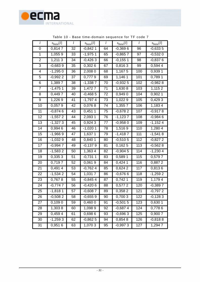
Table 10 - Base t ime-domain sequence for TF code 7
l sbase[l] l sbase[l] l sbase[l] l sbase[l]0 0,814 7 32 -0,842 1 64 -0,369 6 96 -0,633 51 1,055 9 33 -1,975 1 65 -0,865 7 97 -0,532 02 1,211 3 34 -0,426 3 66 -0,155 1 98 -0,837 63 -0,683 9 35 0,302 6 67 0,816 3 99 0,594 44 -1,295 0 36 2,008 0 68 1,167 5 100 0,939 15 -0,992 2 37 0,777 9 69 1,146 1 101 0,789 16 1,389 7 38 -1,338 7 70 -0,932 5 102 -0,982 87 -1,475 1 39 1,472 7 71 1,630 8 103 1,115 28 0,449 7 40 -0,468 5 72 0,949 0 104 0,902 19 1,226 9 41 -1,797 4 73 1,022 9 105 0,429 3
10 0,057 9 42 0,076 8 74 1,355 7 106 1,183 411 -0,874 6 43 0,451 1 75 -0,678 2 107 -0,917 812 -1,557 2 44 2,093 1 76 -1,123 7 108 -0,984 613 -1,327 3 45 0,924 3 77 -0,958 0 109 -1,152 414 0,994 6 46 -1,020 1 78 1,516 9 110 1,280 415 -1,966 9 47 1,637 1 79 -1,418 7 111 -1,541 816 -1,032 9 48 0,840 1 80 -0,510 5 112 -0,827 217 -0,994 7 49 -0,137 9 81 0,162 5 113 -0,562 818 -1,583 2 50 1,363 4 82 -0,904 5 114 -1,230 419 0,335 3 51 -0,731 1 83 0,589 1 115 0,579 720 0,719 7 52 0,061 9 84 0,424 1 116 0,887 221 0,491 4 53 -0,762 4 85 0,624 2 117 0,813 622 -1,534 2 54 1,031 7 86 -0,676 6 118 -1,259 223 0,767 8 55 -0,845 4 87 0,742 1 119 1,179 424 -0,774 7 56 -0,420 6 88 0,577 2 120 -0,389 725 -1,818 1 57 -0,608 7 89 0,358 2 121 -0,797 226 -0,508 2 58 -0,655 9 90 0,700 3 122 -0,128 327 0,109 0 59 0,460 0 91 -0,501 5 123 0,630 128 1,303 8 60 1,098 9 92 -0,687 4 124 0,778 629 0,459 4 61 0,698 6 93 -0,696 3 125 0,900 730 -1,259 3 62 -0,862 5 94 0,854 8 126 -0,818 831 0,951 6 63 1,070 3 95 -0,997 3 127 1,294 7
- 31 -

Table 11 - Base t ime-domain sequence for TF code 8
l sbase[l] l sbase[l] l sbase[l] l sbase[l]0 -1,541 8 32 1,599 1 64 1,272 4 96 -1,085 31 -1,869 3 33 0,981 5 65 1,182 6 97 -1,157 82 0,737 6 34 -0,397 2 66 -1,062 4 98 0,500 23 0,705 3 35 -0,635 9 67 -0,870 3 99 0,783 74 -0,389 4 36 0,995 2 68 0,678 5 100 -0,540 05 0,151 3 37 -0,720 2 69 -0,960 8 101 0,428 96 -0,880 5 38 0,776 5 70 0,480 1 102 -0,610 17 -0,377 9 39 -0,565 1 71 -0,794 7 103 0,417 08 -1,961 0 40 -0,850 1 72 -0,835 3 104 -1,676 49 -2,446 4 41 -0,726 7 73 -0,782 2 105 -1,307 0
10 1,854 8 42 0,799 5 74 0,495 3 106 1,419 811 1,366 2 43 0,710 0 75 0,506 8 107 1,120 112 -0,356 1 44 -0,365 7 76 -0,389 2 108 -1,063 013 0,681 6 45 1,182 5 77 0,345 5 109 1,633 514 -0,874 5 46 -0,220 9 78 -0,337 1 110 -0,419 715 0,145 1 47 0,913 3 79 0,232 7 111 1,450 916 -1,292 6 48 1,355 6 80 -0,401 3 112 1,400 517 -1,922 8 49 1,378 1 81 -0,382 6 113 1,318 718 2,112 7 50 -0,867 7 82 0,422 4 114 -1,205 119 1,323 3 51 -0,601 8 83 0,122 6 115 -1,234 320 -0,149 2 52 0,749 4 84 -0,253 4 116 0,635 421 0,852 0 53 -1,151 0 85 0,504 9 117 -0,932 822 -0,309 7 54 0,385 6 86 -0,047 4 118 0,556 523 0,618 9 55 -0,823 5 87 0,319 7 119 -0,883 424 -0,492 3 56 -1,225 2 88 1,722 4 120 0,627 825 -0,970 4 57 -0,861 1 89 1,415 6 121 0,559 126 1,804 2 58 0,908 0 90 -1,265 0 122 -0,975 927 0,807 6 59 0,931 2 91 -1,249 4 123 -0,744 228 -0,041 8 60 -0,848 6 92 0,955 6 124 0,416 729 1,186 9 61 1,274 6 93 -1,622 7 125 -1,174 930 0,246 4 62 -0,450 0 94 0,454 0 126 -0,086 531 1,049 1 63 1,081 8 95 -1,370 0 127 -1,138 2
- 32 -

Table 12 - Base t ime-domain sequence for TF code 9
l sbase[l] l sbase[l] l sbase[l] l sbase[l]0 -0,450 4 32 1,503 3 64 0,795 4 96 1,319 61 -0,020 4 33 0,580 0 65 0,398 4 97 0,305 12 0,603 8 34 -1,132 4 66 -0,711 4 98 -1,417 73 0,003 7 35 0,885 8 67 0,311 2 99 0,435 84 0,545 4 36 -0,964 2 68 -0,584 5 100 -1,275 85 0,697 5 37 -1,750 0 69 -0,906 4 101 -1,653 46 0,985 9 38 -1,439 5 70 -0,695 6 102 -1,753 17 -0,303 2 39 0,815 0 71 0,374 1 103 0,552 28 1,038 8 40 -0,606 2 72 -0,398 1 104 -0,855 49 1,170 3 41 -1,347 9 73 -0,835 9 105 -1,237 7
10 -0,773 3 42 0,782 5 74 0,634 3 106 0,166 711 1,322 4 43 -1,343 7 75 -0,758 1 107 -1,573 912 -1,313 8 44 1,837 4 76 1,334 8 108 0,686 113 -1,396 5 45 1,434 8 77 0,690 2 109 1,013 414 -1,136 2 46 1,623 3 78 1,518 3 110 -0,074 215 1,104 8 47 -1,328 4 79 -1,070 4 111 -0,655 516 -0,363 5 48 0,946 1 80 1,325 0 112 -1,243 817 -0,886 9 49 1,293 5 81 1,020 8 113 -0,379 818 0,327 4 50 -0,317 1 82 -0,364 3 114 0,805 119 -0,691 7 51 1,464 7 83 1,406 8 115 -1,059 820 1,343 3 52 -1,265 1 84 -0,864 2 116 0,196 921 1,040 0 53 -1,289 4 85 -1,837 7 117 1,102 122 1,127 8 54 -0,210 3 86 0,060 4 118 0,073 923 -0,899 2 55 0,903 5 87 0,411 5 119 -0,008 624 0,916 0 56 1,076 7 88 1,693 3 120 -1,573 225 1,021 1 57 0,403 2 89 0,332 6 121 -0,606 326 -0,195 5 58 -1,128 7 90 -1,309 5 122 1,057 527 1,066 2 59 1,006 6 91 1,283 9 123 -0,819 028 -0,675 2 60 -0,369 2 92 -0,732 7 124 0,840 029 -0,987 6 61 -0,937 7 93 -1,962 3 125 1,708 430 0,160 0 62 -0,663 5 94 -0,870 1 126 0,751 431 0,413 7 63 0,284 2 95 0,192 7 127 -0,250 7
- 33 -

Table 13 - Base t ime-domain sequence for TF code 10
l sbase[l] l sbase[l] l sbase[l] l sbase[l]0 -0,809 9 32 1,028 7 64 -0,091 1 96 -0,704 81 0,816 6 33 -1,775 5 65 0,038 7 97 0,163 22 0,398 2 34 -2,049 8 66 -0,458 7 98 1,589 63 0,825 9 35 -1,220 7 67 0,142 6 99 1,053 14 -0,763 4 36 1,113 5 68 0,737 7 100 -1,793 15 0,160 7 37 -1,505 3 69 -0,685 3 101 0,573 86 -0,649 1 38 0,700 0 70 0,152 5 102 -1,422 57 0,006 2 39 1,746 8 71 0,818 2 103 -1,475 18 0,339 3 40 0,528 4 72 1,092 1 104 0,682 59 -1,080 1 41 -0,089 1 73 -0,464 2 105 -1,705 3
10 -1,385 2 42 -1,588 6 74 -1,231 7 106 -1,138 511 -0,541 0 43 -0,876 9 75 -1,270 4 107 -1,284 012 0,663 0 44 1,466 2 76 1,869 0 108 0,291 513 -1,148 5 45 -0,545 1 77 -0,557 7 109 -1,058 314 0,113 1 46 1,070 8 78 1,686 5 110 0,393 515 1,172 7 47 1,476 5 79 1,141 3 111 0,771 816 0,822 7 48 -0,832 1 80 -0,564 0 112 -0,086 317 -0,429 8 49 1,271 6 81 1,686 9 113 -0,459 318 -1,778 5 50 0,387 8 82 1,690 4 114 -0,853 319 -1,382 6 51 1,135 1 83 1,388 6 115 -0,223 620 1,538 5 52 -0,477 3 84 -0,604 9 116 0,330 821 -0,579 1 53 0,423 9 85 1,370 8 117 -0,670 422 1,416 8 54 -0,720 4 86 -0,530 6 118 -0,172 923 1,144 5 55 0,116 2 87 -1,365 7 119 0,740 024 -1,294 2 56 0,465 7 88 0,040 4 120 0,220 625 1,520 8 57 -0,564 4 89 0,411 1 121 -0,182 526 1,332 4 58 -1,311 7 90 1,228 4 122 -1,356 727 1,542 7 59 -0,656 9 91 0,348 9 123 -0,694 728 -1,066 3 60 0,590 8 92 -1,041 0 124 0,658 629 0,365 6 61 -0,639 9 93 1,100 2 125 -0,306 630 -1,089 1 62 0,663 8 94 -0,246 7 126 0,482 331 -0,434 0 63 1,218 3 95 -1,372 0 127 0,876 6
- 34 -
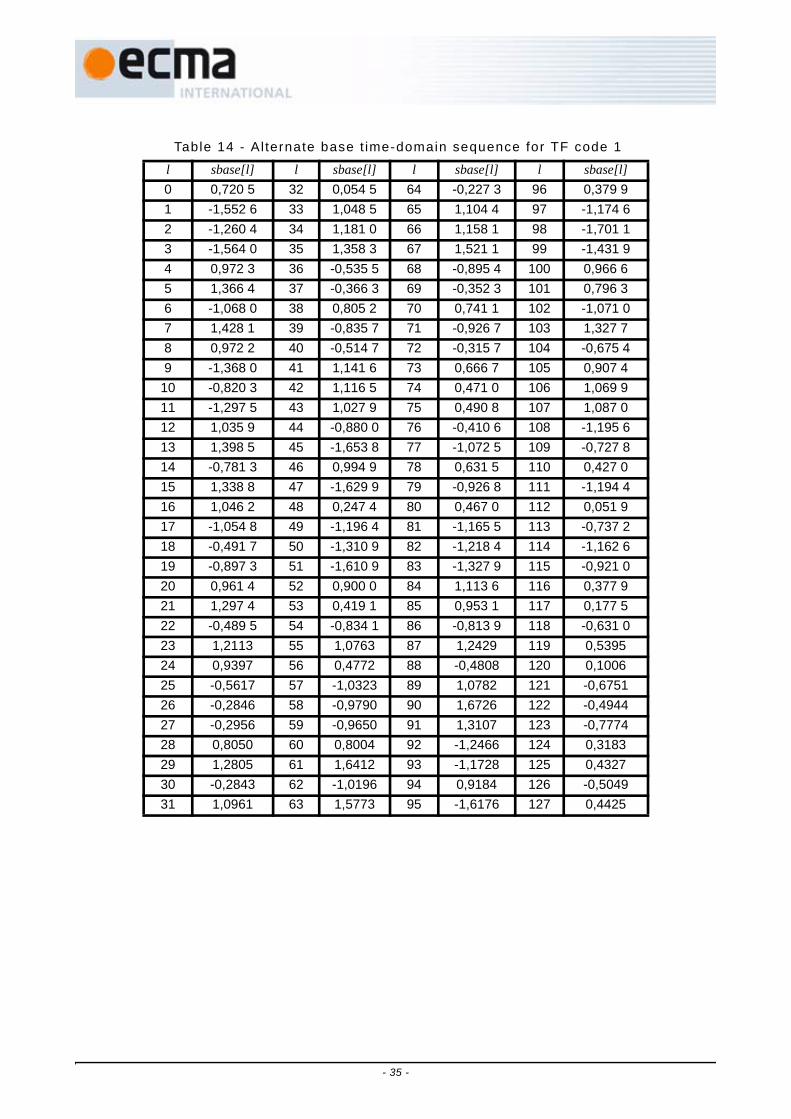
Table 14 - Al ternate base t ime-domain sequence for TF code 1
l sbase[l] l sbase[l] l sbase[l] l sbase[l]0 0,720 5 32 0,054 5 64 -0,227 3 96 0,379 91 -1,552 6 33 1,048 5 65 1,104 4 97 -1,174 62 -1,260 4 34 1,181 0 66 1,158 1 98 -1,701 13 -1,564 0 35 1,358 3 67 1,521 1 99 -1,431 94 0,972 3 36 -0,535 5 68 -0,895 4 100 0,966 65 1,366 4 37 -0,366 3 69 -0,352 3 101 0,796 36 -1,068 0 38 0,805 2 70 0,741 1 102 -1,071 07 1,428 1 39 -0,835 7 71 -0,926 7 103 1,327 78 0,972 2 40 -0,514 7 72 -0,315 7 104 -0,675 49 -1,368 0 41 1,141 6 73 0,666 7 105 0,907 4
10 -0,820 3 42 1,116 5 74 0,471 0 106 1,069 911 -1,297 5 43 1,027 9 75 0,490 8 107 1,087 012 1,035 9 44 -0,880 0 76 -0,410 6 108 -1,195 613 1,398 5 45 -1,653 8 77 -1,072 5 109 -0,727 814 -0,781 3 46 0,994 9 78 0,631 5 110 0,427 015 1,338 8 47 -1,629 9 79 -0,926 8 111 -1,194 416 1,046 2 48 0,247 4 80 0,467 0 112 0,051 917 -1,054 8 49 -1,196 4 81 -1,165 5 113 -0,737 218 -0,491 7 50 -1,310 9 82 -1,218 4 114 -1,162 619 -0,897 3 51 -1,610 9 83 -1,327 9 115 -0,921 020 0,961 4 52 0,900 0 84 1,113 6 116 0,377 921 1,297 4 53 0,419 1 85 0,953 1 117 0,177 522 -0,489 5 54 -0,834 1 86 -0,813 9 118 -0,631 023 1,2113 55 1,0763 87 1,2429 119 0,539524 0,9397 56 0,4772 88 -0,4808 120 0,100625 -0,5617 57 -1,0323 89 1,0782 121 -0,675126 -0,2846 58 -0,9790 90 1,6726 122 -0,494427 -0,2956 59 -0,9650 91 1,3107 123 -0,777428 0,8050 60 0,8004 92 -1,2466 124 0,318329 1,2805 61 1,6412 93 -1,1728 125 0,432730 -0,2843 62 -1,0196 94 0,9184 126 -0,504931 1,0961 63 1,5773 95 -1,6176 127 0,4425
- 35 -

Table 15 - Al ternate base t ime-domain sequence for TF code 2
l sbase[l] l sbase[l] l sbase[l] l sbase[l]0 0,808 0 32 -1,357 7 64 1,574 2 96 0,512 71 -0,858 1 33 1,104 1 65 -1,014 4 97 -0,418 32 0,410 3 34 -1,263 9 66 1,133 5 98 0,136 93 0,375 0 35 -0,829 2 67 1,298 4 99 0,617 94 -1,145 3 36 1,555 8 68 -1,581 0 100 -1,128 75 -1,203 7 37 1,135 2 69 -1,624 1 101 -0,649 26 -0,910 0 38 1,455 2 70 -1,227 0 102 -0,842 07 -0,138 3 39 -0,475 8 71 0,383 4 103 0,197 18 -0,910 3 40 -0,982 1 72 -1,222 5 104 -0,981 69 0,121 1 41 1,027 7 73 0,841 8 105 0,606 6
10 -1,080 7 42 -0,431 4 74 -1,357 3 106 -1,118 011 -0,798 4 43 -0,753 7 75 -0,845 7 107 -0,402 012 0,277 5 44 1,572 6 76 1,000 6 108 0,392 613 0,053 4 45 1,721 6 77 0,811 4 109 0,463 314 0,441 9 46 1,240 9 78 1,147 8 110 0,511 715 -0,888 5 47 -0,211 7 79 -0,571 5 111 -0,304 116 -1,406 6 48 1,626 2 80 -0,811 7 112 -0,915 617 0,581 5 49 -0,667 7 81 0,719 9 113 0,597 218 -1,386 9 50 1,115 7 82 -0,321 3 114 -0,437 619 -1,099 4 51 1,461 4 83 -0,887 7 115 -0,795 920 1,091 4 52 -1,385 2 84 1,568 8 116 1,187 921 0,675 0 53 -1,359 6 85 1,198 4 117 0,981 722 1,158 7 54 -1,163 2 86 1,176 0 118 0,942 423 -1,043 6 55 0,809 0 87 -0,248 2 119 -0,316 824 -1,349 9 56 -1,202 3 88 1,469 5 120 1,279 425 0,845 2 57 1,005 6 89 -0,849 4 121 -0,850 026 -1,359 5 58 -0,810 6 90 1,453 4 122 1,264 827 -0,936 7 59 -0,895 5 91 0,887 5 123 0,608 928 1,311 1 60 1,166 8 92 -0,955 6 124 -0,825 929 0,897 8 61 1,618 6 93 -0,921 2 125 -0,954 430 1,337 7 62 0,932 7 94 -1,075 1 126 -0,937 331 -0,842 0 63 -0,313 3 95 0,606 1 127 0,345 4
- 36 -

Table 16 - Al ternate base t ime-domain sequence for TF code 3
l sbase[l] l sbase[l] l sbase[l] l sbase[l]0 0,484 2 32 -1,036 8 64 -0,749 8 96 0,292 21 0,776 1 33 -1,058 0 65 -1,040 8 97 0,650 52 -0,455 5 34 0,795 7 66 1,112 1 98 -0,723 83 0,641 1 35 -0,816 0 67 -0,893 1 99 0,833 94 0,232 9 36 -0,852 2 68 -1,019 1 100 0,923 15 -0,921 0 37 1,680 5 69 1,678 1 101 -0,688 56 -0,757 2 38 0,962 6 70 0,839 7 102 -0,369 07 -0,815 4 39 1,457 5 71 1,654 4 103 -0,920 68 0,384 6 40 0,253 5 72 0,158 3 104 -0,252 69 0,672 6 41 0,934 7 73 1,215 0 105 -1,099 8
10 -1,027 0 42 -1,167 6 74 -1,537 7 106 1,728 911 0,454 9 43 1,188 7 75 1,487 0 107 -1,364 212 0,293 6 44 1,097 9 76 0,997 7 108 -0,934 313 -1,397 7 45 -0,738 5 77 -0,752 6 109 0,948 914 -1,020 9 46 -0,566 2 78 -0,930 2 110 1,075 415 -1,268 6 47 -1,275 6 79 -1,243 8 111 1,461 916 -0,791 5 48 -0,249 7 80 -0,667 7 112 0,480 817 -1,518 5 49 -1,020 3 81 -1,303 6 113 0,823 018 1,084 6 50 1,199 2 82 1,721 9 114 -0,909 019 -1,913 5 51 -1,229 1 83 -1,717 1 115 1,090 220 -1,517 2 52 -0,553 1 84 -1,259 9 116 0,799 821 0,650 1 53 0,257 7 85 0,884 6 117 -0,188 422 0,640 4 54 0,784 8 86 1,025 3 118 -0,351 723 1,247 0 55 0,697 2 87 1,541 2 119 -0,605 624 -1,002 5 56 -0,067 2 88 -0,460 7 120 0,672 425 -1,319 8 57 -0,666 1 89 -0,896 2 121 1,187 426 0,512 4 58 0,402 0 90 0,846 5 122 -0,893 727 -1,301 7 59 -0,728 4 91 -0,909 2 123 1,234 228 -1,058 1 60 -0,243 8 92 -0,670 0 124 0,862 829 1,403 4 61 0,575 5 93 1,378 7 125 -1,105 930 0,784 4 62 0,491 9 94 0,979 7 126 -0,856 431 1,376 1 63 0,614 4 95 1,240 7 127 -1,188 7
- 37 -

Table 17 - Al ternate base t ime-domain sequence for TF code 4
l sbase[l] l sbase[l] l sbase[l] l sbase[l]0 0,942 3 32 -1,005 4 64 1,325 4 96 -0,968 71 0,787 9 33 -0,672 2 65 0,764 0 97 -0,724 52 0,563 4 34 -0,628 5 66 1,428 5 98 -1,030 73 -0,587 3 35 0,948 1 67 -0,986 5 99 0,640 94 -1,103 8 36 0,989 5 68 -1,016 8 100 0,935 55 0,996 1 37 -1,371 7 69 0,691 0 101 -0,469 36 -0,861 1 38 0,727 0 70 -1,069 7 102 1,032 37 -0,171 3 39 0,364 0 71 -0,770 7 103 0,930 08 -0,609 3 40 1,504 4 72 0,797 4 104 -1,427 29 -0,320 9 41 1,105 5 73 0,353 0 105 -0,854 4
10 -0,768 2 42 0,952 6 74 0,274 1 106 -1,407 211 0,330 1 43 -1,303 8 75 -1,072 8 107 1,275 812 0,316 6 44 -1,856 8 76 -1,382 3 108 1,529 213 -0,156 5 45 1,791 1 77 0,750 2 109 -0,794 114 0,402 8 46 -1,518 1 78 -1,081 9 110 1,506 015 0,190 9 47 -0,390 8 79 -0,535 4 111 1,105 216 -1,030 3 48 -1,693 6 80 -1,579 3 112 -0,866 817 -0,746 2 49 -0,943 1 81 -1,217 7 113 -0,407 118 -0,412 3 50 -1,686 6 82 -1,612 4 114 -0,506 119 0,915 7 51 1,059 8 83 0,522 1 115 1,187 020 1,491 8 52 1,029 6 84 0,852 9 116 1,466 021 -1,388 6 53 -1,061 6 85 -1,174 5 117 -0,730 622 1,216 7 54 1,090 1 86 0,993 5 118 1,152 423 0,378 8 55 0,613 1 87 0,509 1 119 0,663 224 1,695 3 56 -0,630 7 88 -1,407 9 120 0,857 725 0,911 6 57 -0,458 3 89 -1,164 9 121 0,773 326 1,267 0 58 -0,146 6 90 -1,266 2 122 0,980 327 -1,203 2 59 0,546 4 91 0,732 9 123 -0,123 528 -1,222 2 60 1,047 6 92 1,308 0 124 -0,345 929 1,584 7 61 -0,873 5 93 -1,176 9 125 0,663 130 -1,079 1 62 0,658 9 94 1,255 5 126 -0,526 231 -0,621 8 63 -0,071 7 95 0,758 0 127 -0,139 5
- 38 -

Table 18 - Al ternate base t ime-domain sequence for TF code 5
l sbase[l] l sbase[l] l sbase[l] l sbase[l]0 0,780 5 32 0,953 5 64 0,580 6 96 -0,873 91 0,599 4 33 1,154 5 65 -0,048 3 97 -0,369 72 1,439 2 34 1,248 8 66 1,033 7 98 -1,300 33 -0,049 2 35 -0,520 4 67 -0,732 5 99 0,725 34 -0,306 2 36 -1,576 9 68 -0,660 4 100 0,460 15 -0,111 9 37 -0,840 0 69 -0,721 5 101 0,768 06 1,131 8 38 1,498 2 70 0,841 7 102 -1,228 57 -0,237 9 39 -1,389 5 71 -0,883 9 103 0,953 88 1,031 0 40 0,320 6 72 -0,750 7 104 0,327 39 1,988 8 41 1,517 5 73 -0,351 0 105 -0,084 8
10 0,996 9 42 -0,161 2 74 -0,904 8 106 0,612 911 -0,284 8 43 -0,497 1 75 0,691 8 107 -0,672 712 -1,435 0 44 -1,556 1 76 0,860 1 108 -0,482 713 -0,718 9 45 -0,850 2 77 0,893 3 109 -0,787 014 1,715 6 46 1,057 5 78 -1,163 2 110 0,783 815 -1,344 0 47 -1,485 2 79 1,322 7 111 -1,052 216 0,458 2 48 0,295 9 80 0,802 4 112 -0,547 217 1,635 8 49 0,644 0 81 0,758 7 113 -1,000 218 -0,157 4 50 -0,265 5 82 1,268 8 114 -0,615 519 -0,105 9 51 -0,650 2 83 -0,452 5 115 0,378 020 -1,378 3 52 -1,106 0 84 -1,153 3 116 1,491 321 -0,583 5 53 -0,937 3 85 -0,812 5 117 0,665 222 0,907 6 54 0,452 5 86 1,129 1 118 -0,995 823 -1,153 4 55 -1,319 1 87 -1,175 2 119 1,114 624 -0,804 7 56 -1,120 1 88 0,356 8 120 -0,442 125 -0,148 1 57 -1,248 6 89 1,305 5 121 -1,421 326 -1,349 8 58 -1,427 9 90 0,160 4 122 -0,132 427 1,113 0 59 0,739 3 91 -0,509 9 123 0,694 328 0,487 8 60 1,176 8 92 -1,480 4 124 1,781 629 1,227 5 61 1,073 5 93 -0,961 0 125 1,114 430 -1,197 5 62 -1,730 1 94 0,942 5 126 -0,884 931 1,461 6 63 1,605 8 95 -1,540 2 127 1,708 3
- 39 -

Table 19 - Al ternate base t ime-domain sequence for TF code 6
l sbase[l] l sbase[l] l sbase[l] l sbase[l]0 0,808 0 32 -0,490 3 64 1,080 4 96 0,908 01 -0,511 6 33 0,444 2 65 -1,022 3 97 -1,172 22 0,520 4 34 -0,379 9 66 0,706 0 98 0,443 13 0,633 7 35 -0,235 7 67 1,102 4 99 1,300 44 0,367 1 36 -0,295 3 68 0,531 2 100 0,031 35 0,054 2 37 0,532 7 69 -0,826 3 101 -0,469 76 -0,688 7 38 -0,039 4 70 -0,565 3 102 -1,834 67 -0,187 5 39 0,387 1 71 -0,529 9 103 -0,757 38 0,930 9 40 0,778 3 72 -1,135 7 104 0,769 39 -1,028 9 41 -0,764 1 73 1,257 6 105 -1,553 3
10 0,657 7 42 0,599 8 74 -0,921 9 106 0,501 811 0,774 0 43 0,616 3 75 -0,263 2 107 0,691 712 0,478 5 44 0,541 0 76 -0,824 6 108 0,338 413 -1,095 5 45 -0,986 7 77 1,433 9 109 -1,667 314 -0,413 4 46 -0,045 6 78 0,160 2 110 -1,005 615 -0,723 8 47 -0,546 5 79 0,951 7 111 -1,092 216 -1,624 9 48 -1,529 5 80 1,531 9 112 -1,825 817 1,376 9 49 1,605 5 81 -0,868 0 113 0,854 518 -1,191 6 50 -1,098 9 82 0,868 7 114 -1,213 419 -1,091 0 51 -0,988 8 83 1,950 8 115 -1,533 520 -0,927 2 52 -0,803 2 84 0,418 9 116 -0,731 221 1,177 1 53 1,595 5 85 0,253 2 117 -0,034 222 0,554 9 54 0,854 6 86 -1,635 0 118 1,259 623 0,901 3 55 1,036 4 87 -0,321 2 119 0,359 024 1,219 4 56 1,947 4 88 1,588 2 120 -1,403 725 -1,015 5 57 -1,248 3 89 -1,337 6 121 1,329 526 0,831 0 58 1,352 3 90 0,877 1 122 -0,897 727 1,000 3 59 1,471 4 91 2,103 3 123 -1,374 128 0,642 9 60 0,959 4 92 0,330 0 124 -0,581 629 -0,691 4 61 -0,426 3 93 -0,378 0 125 1,148 130 -0,610 8 62 -1,191 5 94 -1,998 1 126 1,181 531 -0,602 9 63 -0,615 1 95 -0,817 2 127 0,770 2
- 40 -

Table 20 - Al ternate base t ime-domain sequence for TF code 7
l sbase[l] l sbase[l] l sbase[l] l sbase[l]0 0,770 2 32 -0,817 2 64 -0,615 1 96 -0,602 91 1,181 5 33 -1,998 1 65 -1,191 5 97 -0,610 82 1,148 1 34 -0,378 0 66 -0,426 3 98 -0,691 43 -0,581 6 35 0,330 0 67 0,959 4 99 0,642 94 -1,374 1 36 2,103 3 68 1,471 4 100 1,000 35 -0,897 7 37 0,877 1 69 1,352 3 101 0,831 06 1,329 5 38 -1,337 6 70 -1,248 3 102 -1,015 57 -1,403 7 39 1,588 2 71 1,947 4 103 1,219 48 0,359 0 40 -0,321 2 72 1,036 4 104 0,901 39 1,259 6 41 -1,635 0 73 0,854 6 105 0,554 9
10 -0,034 2 42 0,253 2 74 1,595 5 106 1,177 111 -0,731 2 43 0,418 9 75 -0,803 2 107 -0,927 212 -1,533 5 44 1,950 8 76 -0,988 8 108 -1,091 013 -1,213 4 45 0,868 7 77 -1,098 9 109 -1,191 614 0,854 5 46 -0,868 0 78 1,605 5 110 1,376 915 -1,825 8 47 1,531 9 79 -1,529 5 111 -1,624 916 -1,092 2 48 0,951 7 80 -0,546 5 112 -0,723 817 -1,005 6 49 0,160 2 81 -0,045 6 113 -0,413 418 -1,667 3 50 1,433 9 82 -0,986 7 114 -1,095 519 0,338 4 51 -0,824 6 83 0,541 0 115 0,478 520 0,691 7 52 -0,263 2 84 0,616 3 116 0,774 021 0,501 8 53 -0,921 9 85 0,599 8 117 0,657 722 -1,553 3 54 1,257 6 86 -0,764 1 118 -1,028 923 0,769 3 55 -1,135 7 87 0,778 3 119 0,930 924 -0,757 3 56 -0,529 9 88 0,387 1 120 -0,187 525 -1,834 6 57 -0,565 3 89 -0,039 4 121 -0,688 726 -0,469 7 58 -0,826 3 90 0,532 7 122 0,054 227 0,031 3 59 0,531 2 91 -0,295 3 123 0,367 128 1,300 4 60 1,102 4 92 -0,235 7 124 0,633 729 0,443 1 61 0,706 0 93 -0,379 9 125 0,520 430 -1,172 2 62 -1,022 3 94 0,444 2 126 -0,511 631 0,908 0 63 1,080 4 95 -0,490 3 127 0,808 0
- 41 -

Table 21 - Cover sequence for Standard preamble
m scover[m] for TF codes 1,2
scover[m] for TF codes 3,4
scover[m] for TF codes 5,6,7
scover[m] for TF codes 8,9,10
0 1 1 -1 11 1 1 -1 12 1 1 -1 -13 1 1 -1 -14 1 1 -1 15 1 1 -1 16 1 1 -1 -17 1 1 1 -18 1 1 -1 19 1 1 -1 1
10 1 1 1 -111 1 1 -1 -112 1 1 -1 113 1 1 1 114 1 1 -1 -115 1 1 -1 -116 1 1 1 117 1 1 -1 118 1 1 -1 119 1 -1 1 120 1 1 -1 121 -1 -1 1 122 -1 1 1 -123 -1 -1 1 -1
- 42 -

Table 22 - Cover sequence for burst preamble
m scover[m] for TF codes 1,2
scover[m] for TF codes 3,4
scover[m] for TF codes 5,6,7
scover[m] for TF codes 8,9,10
0 1 1 -1 11 1 1 -1 12 1 1 -1 -13 1 1 1 -14 1 1 1 15 1 1 -1 16 1 1 -1 17 1 -1 1 18 1 1 -1 19 -1 -1 1 1
10 -1 1 1 -111 -1 -1 1 -1
- 43 -

Table 23 - Base frequency-domain channel est imat ion sequence
Tone Value Tone Value Tone Value Tone Value-61 (−1+j) ⁄ √2 -30 (1−j) ⁄ √2 1 (1+j) ⁄ √2 32 (1+j) ⁄ √2
-60 (−1+j) ⁄ √2 -29 (−1+j) ⁄ √2 2 (1+j) ⁄ √2 33 (1+j) ⁄ √2
-59 (−1+j) ⁄ √2 -28 (−1+j) ⁄ √2 3 (−1−j) ⁄ √2 34 (−1−j) ⁄ √2
-58 (−1+j) ⁄ √2 -27 (1−j) ⁄ √2 4 (1+j) ⁄ √2 35 (−1−j) ⁄ √2
-57 (−1+j) ⁄ √2 -26 (1−j) ⁄ √2 5 (−1−j) ⁄ √2 36 (1+j) ⁄ √2
-56 (1−j) ⁄ √2 -25 (1−j) ⁄ √2 6 (−1−j) ⁄ √2 37 (−1−j) ⁄ √2
-55 (1−j) ⁄ √2 -24 (−1+j) ⁄ √2 7 (1+j) ⁄ √2 38 (1+j) ⁄ √2
-54 (−1+j) ⁄ √2 -23 (1−j) ⁄ √2 8 (−1−j) ⁄ √2 39 (1+j) ⁄ √2
-53 (1−j) ⁄ √2 -22 (1−j) ⁄ √2 9 (1+j) ⁄ √2 40 (1+j) ⁄ √2
-52 (1−j) ⁄ √2 -21 (1−j) ⁄ √2 10 (−1−j) ⁄ √2 41 (−1−j) ⁄ √2
-51 (1−j) ⁄ √2 -20 (−1+j) ⁄ √2 11 (1+j) ⁄ √2 42 (−1−j) ⁄ √2
-50 (1−j) ⁄ √2 -19 (1−j) ⁄ √2 12 (1+j) ⁄ √2 43 (1+j) ⁄ √2
-49 (1−j) ⁄ √2 -18 (−1+j) ⁄ √2 13 (−1−j) ⁄ √2 44 (1+j) ⁄ √2
-48 (−1+j) ⁄ √2 -17 (1−j) ⁄ √2 14 (−1−j) ⁄ √2 45 (−1−j) ⁄ √2
-47 (1−j) ⁄ √2 -16 (1−j) ⁄ √2 15 (−1−j) ⁄ √2 46 (−1−j) ⁄ √2
-46 (−1+j) ⁄ √2 -15 (−1+j) ⁄ √2 16 (1+j) ⁄ √2 47 (1+j) ⁄ √2
-45 (−1+j) ⁄ √2 -14 (−1+j) ⁄ √2 17 (1+j) ⁄ √2 48 (−1−j) ⁄ √2
-44 (1−j) ⁄ √2 -13 (−1+j) ⁄ √2 18 (−1−j) ⁄ √2 49 (1+j) ⁄ √2
-43 (1−j) ⁄ √2 -12 (1−j) ⁄ √2 19 (1+j) ⁄ √2 50 (1+j) ⁄ √2
-42 (−1+j) ⁄ √2 -11 (1−j) ⁄ √2 20 (−1−j) ⁄ √2 51 (1+j) ⁄ √2
-41 (−1+j) ⁄ √2 -10 (−1+j) ⁄ √2 21 (1+j) ⁄ √2 52 (1+j) ⁄ √2
-40 (1−j) ⁄ √2 -9 (1−j) ⁄ √2 22 (1+j) ⁄ √2 53 (1+j) ⁄ √2
-39 (1−j) ⁄ √2 -8 (−1+j) ⁄ √2 23 (1+j) ⁄ √2 54 (−1−j) ⁄ √2
-38 (1−j) ⁄ √2 -7 (1−j) ⁄ √2 24 (−1−j) ⁄ √2 55 (1+j) ⁄ √2
-37 (−1+j) ⁄ √2 -6 (−1+j) ⁄ √2 25 (1+j) ⁄ √2 56 (1+j) ⁄ √2
-36 (1−j) ⁄ √2 -5 (−1+j) ⁄ √2 26 (1+j) ⁄ √2 57 (−1−j) ⁄ √2
-35 (−1+j) ⁄ √2 -4 (1−j) ⁄ √2 27 (1+j) ⁄ √2 58 (−1−j) ⁄ √2
-34 (−1+j) ⁄ √2 -3 (−1+j) ⁄ √2 28 (−1−j) ⁄ √2 59 (−1−j) ⁄ √2
-33 (1−j) ⁄ √2 -2 (1−j) ⁄ √2 29 (−1−j) ⁄ √2 60 (−1−j) ⁄ √2
-32 (1−j) ⁄ √2 -1 (1−j) ⁄ √2 30 (1+j) ⁄ √2 61 (−1−j) ⁄ √2
-31 (1−j) ⁄ √2 31 (1+j) ⁄ √2
- 44 -

10.3 PLCP header A PLCP header shall be added after the PLCP preamble to convey information about both thePHY and the MAC that is needed at the receiver in order to successfully decode the PSDU.The scrambled and Reed-Solomon encoded PLCP header shall be formed as defined inFigure 11:
1. Format the PHY header based on information provided by the MAC.
2. Calculate the HCS value (2 octets) over the combined PHY and MAC headers.
3. The resulting HCS value is appended to the MAC header. The resulting combination (MACHeader + HCS) is scrambled according to 10.5.
4. Apply a shortened Reed-Solomon code (23,17) to the concatenation of the PHY header(5 octets), scrambled MAC header and HCS (12 octets).
5. Insert 6 tail bits after the PHY header, 6 tail bits after the scrambled MAC header and HCS, andappend the 6 parity octets and 4 tail bits at the end to form the scrambled and Reed-Solomonencoded PLCP header.
The resulting scrambled and Reed-Solomon encoded PLCP header is encoded, as defined inFigure 12, using a R = 1/3, K = 7 convolutional code (see 10.7), interleaved using a bitinterleaver (see 10.8), mapped onto a QPSK constellation (see 10.9), and finally, theresulting complex values are loaded onto the data subcarriers for the IDFT (see 10.10) inorder to create the baseband signal. Tone-nulling (see 9.2), if implemented, is the applied.
10.3.1 PHY headerThe PHY header contains information about the data rate of the MAC frame body, thelength of the frame payload (which does not include the FCS), the seed identifier for thedata scrambler, and information about the next packet – whether it is being sent in burstmode and whether it employs a burst preamble or not.
The PHY header field shall be composed of 40 bits, numbered from 0 to 39 as defined inFigure 13. Bits 3-7 shall encode the RATE field, which conveys the information about thetype of modulation, the coding rate, and the spreading factor used to transmit the MACframe body. Bits 8-19 shall encode the LENGTH field, with the least-significant bit beingtransmitted first. Bits 22-23 shall encode the seed value for the initial state of thescrambler, which is used to synchronize the descrambler of the receiver. Bit 26 shallencode whether or not the packet is being transmitted in burst mode. Bit 27 shall encodethe preamble type (Standard or burst preamble) used in the next packet if in burst mode.Bits 28-30 shall be used to indicate the lower 3 LSBs of the TFC (T1 - T3) used at thetransmitter. Bit 31 shall be used to indicate the LSB of the band group used at thetransmitter. Bit 34 shall be used to indicate the MSB of the TFC (T4) used at thetransmitter. All other bits which are not defined in this Clause shall be understood to bereserved for future use and shall be set to ZERO.The receiver shall ignore reserved bitson receive. The receiver shall not assume that reserved bits are ZERO on receive, forinstance to assist the Viterbi algorithm or to decode the RATE quickly.
- 45 -
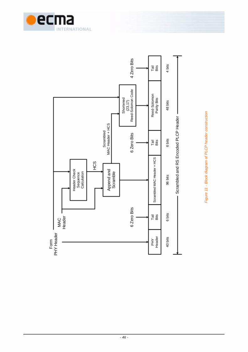
Form
PHY
Hea
der
Hea
der C
heck
S
eque
nce
Cal
cula
tion
MA
CH
eade
r
Appe
nd a
ndSc
ram
ble
HC
S
6 Ze
ro B
its6
Zero
Bits
4 Ze
ro B
its
Sho
rtene
d(2
3,17
)R
eed-
Sol
omon
Cod
e
Scr
ambl
edM
AC
Hea
der +
HC
S
Scra
mbl
ed a
nd R
S E
ncod
ed P
LCP
Hea
der
Scra
mbl
ed M
AC H
eade
r + H
CS
PH
YH
eade
rTa
ilBi
tsTa
ilB
itsR
eed-
Solo
mon
Par
ity B
itsTa
ilB
its
40 b
its6
bits
96 b
its48
bits
6 bi
ts4
bits
Fig
ure
11 -
Blo
ck d
iagr
am o
f PLC
P h
eade
r con
stru
ctio
n
- 46 -

10.3.1.1 Data rate f ield (RATE)Depending on the data rate (RATE), bits R1–R5 shall be set according to the values inTable 24.
10.3.1.2 PLCP length f ield (LENGTH)The PLCP length field shall be an unsigned 12-bit integer that indicates the number ofoctets in the frame payload (which does not include the FCS, the tail bits, or the padbits).
Table 24 - Rate-dependent parameters
Rate (Mb/s) R1 - R5
53,3 00000
80 00001
106,7 00010
160 00011
200 00100
320 00101
400 00110
480 00111
Reserved 01000 − 11111
Scrambled and RS Encoded PLCP Header
ConvolutionalEncoder
BitInterleaver
QPSKMapper
OFDMModulator shdr ,n[k]
dhdr[k]
Figure 12 - Encoding process for the scrambled, Reed-Solomon encoded PLCP header
Figure 13 - PHY Header bit assignment
0 1 3 4 5 6 72 8 9 10 11 12 13 14 15 16 17LSB MSB S2S1
LENGTH(12 bits)
SCRAMBLER(2 bits)
R: Reserved
Transmit Order (from left to right)
R R1 R2 R3 R4
RATE(5 bits)
R18 19 20 21 22
R23 24
R R5R R25 26 27R BMPT
28 29 30 31 32 33R R
34 35 36R R
37 38 39R R RT1 T2 T3
BU
RST
MO
DE
PREA
MB
LE T
YPE
BA
ND
GR
OU
P LS
B
T4
TX_TFC(4 bits)
- 47 -

10.3.1.3 PLCP scrambler f ield (SCRAMBLER)The MAC shall set bits S1–S2 according to the scrambler seed identifier value. This two-bit value corresponds to the seed value chosen for the data scrambler.
10.3.1.4 Burst mode (BM) f ieldThe MAC shall set the burst mode (BM) bit, as defined in Table 25, to indicate whetherthe next packet is part of a packet “burst”, i.e. burst mode transmission. Support fortransmission and reception of burst mode is mandatory. In burst mode, the inter-framespacing shall be equal to pMIFS (see 11.3).
In burst mode, the minimum value of LENGTH shall be 1; while, in standard mode, theminimum value of LENGTH shall be 0.
10.3.1.5 Preamble type (PT) f ieldThe MAC shall set the preamble type (PT) bit in burst mode to indicate the type of PLCPpreamble (standard or burst) used in the next packet according to Table 26. For datarates of 200 Mb/s and below, the PT bit shall be always set to ZERO (consistent with10.2).
The preamble type bit only has meaning during a burst mode transmission. Whendevices are not in a burst mode transmission, the value of the preamble type bit shall beset to ZERO.
10.3.1.6 TF code used at the transmitter (TX_TFC) f ieldThe MAC shall configure the TX_TFC field to indicate the time-frequency code used atthe transmitter for the current packet. Depending on the time-frequency code used, bitsT1–T4 shall be set according to the values in Table 27.
Table 25 - Burst Mode f ie ld
Burst Mode (BM) bit Next Packet Status
ONE Next packet is not part of burst
ZERO Next packet is part of burst
Table 26 - Preamble Type f ie ld
Preamble Type (PT) bit Type of Preamble Used for Next Packet
ZERO Standard Preamble
ONE Burst Preamble
Table 27 - Encoding of the TX_TFC f ie ld
TF Code T1 - T4
1 1000
2 0100
3 1100
4 0010
- 48 -

10.3.1.7 LSB of band group used at the transmitter (BG_LSB) f ieldThe MAC shall configure the BG_LSB field to indicate the LSB of the Band Group usedat the transmitter for the current packet. Depending on the Band Group used at thetransmitter, bit BG_LSB shall be set according to the values in Table 28.
10.3.2 Reed-Solomon outer code for the PLCP headerThe PLCP header shall use a systematic (23, 17) Reed-Solomon outer code to improveupon the robustness of the R = 1/3, K = 7 inner convolutional code. The Reed-Solomoncode is defined over GF(28) with a primitive polynomial p(z) = z8 + z4 + z3 + z2 + 1, where α isthe root of the polynomial p(z). For brevity, this Galois field is denoted as F. As notation, theelement M = b7z7 + b6z6 + b5z5 + b4z4 + b3z3 + b2z2 + b1z + b0, where M ∈ F, has the followingbinary representation b7b6b5b4b3b2b1b0, where b7 is the MSB and b0 is the LSB.
The generator polynomial is obtained by shortening a systematic (255, 249) Reed-Solomon code, which is specified by the generator polynomial
g(x) = (x − αi) = x6 + 126x5 + 4x4 + 158x3 + 58x2 + 49x + 117, (7)
where g(x) is the generator polynomial over F, x ∈ F and the coefficients are given indecimal notation.
The mapping of the information octets m = (m248, m247, …, m0) to codeword octets c =(m248, m247, …, m0, r5, r4, …, r0) is achieved by computing the remainder polynomial r(x)
5 1010
6 0110
7 1110
8 0001
9 1001
10 0101
Reserved all other values
Table 28 - Encoding of the BG_LSB f ie ld
Band Group Band Group LSB (BG_LSB)
1, 3, 5 1
2, 4, 6 0
Table 27 - Encoding of the TX_TFC f ie ld (concluded)
TF Code T1 - T4
i 1=
6
∏
- 49 -

r(x) = rixi = x6m(x) mod g(x), (8)
where m(x) is the information polynomial
m(x) = mixi, (9)
and ri, i = 0, …, 5, and mi, i = 0, …, 248, are elements of F.
The shortening operation pre-appends 232 zero elements to the incoming 17 octetmessage as follows
mi = 0, i = 17, …, 248, (10)
where the 17 octet message is formed by concatenating the 5 octets from the PHY headerto the 12 octets from the scrambled MAC header and HCS. The message order is asfollows: m16 is the first octet of the PHY header, m15 is the second octet of the PHY, m12 isthe last octet of the PHY, m11 is the first octet of the scrambled MAC header and HCS, m11is the first octet of the scrambled MAC header and HCS and m0 is the last octet of thescrambled MAC header and HCS. The bit mapping within the PLCP header is LSB first,such that the first bit of the PLCP header (or PHY header) is mapped to the LSB of m16, the9th bit of the PLCP header is mapped to the LSB of m15, and so on. The order of parityoctets is as follows: r5 is the first octet, r4 is the second octet, and r0 is the last octet of theReed-Solomon parity section. Again, the mapping within the Reed-Solomon parity sectionof the PLCP header is LSB first, such that the first bit of the Reed-Solomon parity ismapped to the LSB of r5, the 9th bit of the Reed-Solomon parity is mapped to the LSB of r4,and so on. A shift-register implementation of this operation is defined in Figure 14, withadditions and multiplications over F. After m0 has been inserted into the shift register, theswitch shall be moved from the message polynomial input connection to the shift registeroutput connection (right-to-left).
i 0=
5
∑
i 0=
248
∑
- 50 -

DD
DD
DD
g 0g 1
g 2g 3
g 4g 5
r 0r 1
r 2r 3
r 4r 5
Cod
ewor
d Po
lyno
mia
l:m
(x)x
6+
r(x)
(out
putm
248fir
st,r
0la
st)
Tran
smit
Shor
tene
d C
ode:
m16
first
,r0
last
Mes
sage
Pol
ynom
ial:
m(x
)x6
(inpu
tm24
8fir
st, m
0la
st)
Switc
h m
oves
whe
nm
0is
inse
rted
into
th
e sh
ift re
gist
er
Fig
ure
14 -
Shi
ft-re
gist
er im
plem
enta
tion
of s
yste
mat
ic R
eed-
Sol
omon
enc
oder
- 51 -

10.3.3 Header check sequenceThe combination of PHY header and the MAC header shall be protected with a 2 octetCCITT CRC-16 header check sequence (HCS). The CCITT CRC-16 HCS shall be the onescomplement of the remainder generated by the modulo-2 division of the combined PHYand MAC headers by the polynomial: x16 + x12 + x5 + 1. The HCS bits shall be processed inthe transmit order. All HCS calculations shall be made prior to data scrambling. Aschematic of the processing order is defined in Figure 15. The registers shall be initializedto all ONEs.
10.4 PSDUThe PSDU is the last major component of the PPDU and shall be constructed as defined inFigure 16:
1. Form the non-scrambled PSDU by appending the frame payload with the 4-octet FCS, six tailbits, and a sufficient number of pad bits (see 10.4.1) in order to ensure that the PSDU is alignedon the interleaver boundary.
CC
ITT
CR
C-1
6
Ser
ial
Dat
aIn
put
Pres
etR
egis
ter
to O
NE
S
Seria
lD
ata
Out
put
DD
DD
Ser
ial
Dat
aIn
put
DD
DD
DD
DD
DD
DD
MSB
LSB
ON
ES
Com
plem
ent
Ser
ial
Dat
aO
utpu
t
(MS
B F
irst)
Fig
ure
15 -
CC
ITT
CR
C-1
6 bl
ock
diag
ram
- 52 -

2. The resulting combination is scrambled according to 10.5.
3. The six tail bits in the PSDU shall be produced by replacing the six scrambled “ZERO” bits withsix non-scrambled “ZERO” bits (see 10.6).
The resulting scrambled PSDU is encoded, as defined in Figure 17, using a R = 1/3, K = 7convolutional code and punctured to achieve the appropriate coding rate (see 10.7),interleaved using a bit interleaver (see 10.8), mapped onto either a QPSK or DCMconstellation (see 10.9), and finally, the resulting complex values are loaded onto the datasubcarriers of the OFDM symbol (see 10.10) in order to create the real or complex basebandsignal, depending on the desired data rate. Tone-nulling (see 9.2), if implemented, is thenapplied.
When the PLCP length field (i.e., the length of the frame payload) is zero, the length of thePSDU shall also be zero.
10.4.1 Pad bitsPad bits shall be appended after the 6 tail bits prior to scrambling and encoding in order toensure that the resulting PSDU is aligned with the boundaries of the bit interleaver defined
Frame Payload
Append andScramble
Scrambled PSDU
FCS 6 Zero Bits(Tail Bits) Pad Bits
ScrambledFrame Payload
ScrambledFCS
UnscrambledTail Bits
ScrambledPad Bits
6 Zero Bits
32 bits 6 bits
Figure 16 - Block diagram of PSDU construction
ScrambledPSDU
ConvolutionalEncoder / Puncturer
BitInterleaver
QPSK or DCMMapper
OFDMModulator sframe,n[k]
dframe[k]
Figure 17 - Block diagram of the encoding process for the scrambled PSDU
- 53 -

in 10.8. The number of pad bits, Npad, that shall be inserted is a function of the number ofinformation bits per 6 OFDM symbols NIBP6S and the number of octets in the frame payload:
Npad = NIBP6S × − (8 × LENGTH + 38), (11)
where LENGTH specifies the number of octets in the frame payload and is definedaccording to 10.3.1.2, and where the value 38 represents the length in bits of the FCS andtail bits section when the length of the PLCP length field is non-zero (LENGTH > 0). Theappended pad bits shall be set to ZEROs and scrambled with the rest of the PSDU.
10.5 Data scramblerA side-stream scrambler shall be used to whiten only portions of the PLCP header, i.e., theMAC header and HCS, and the entire PSDU. In addition, the scrambler shall be initialized toa seed value specified by the MAC at the beginning of the MAC header and then re-initializedto the same seed value at the beginning of the PSDU.
The polynomial generator, g(D), for the pseudo-random binary sequence (PRBS) generatorshall be: g(D) = 1 + D14 + D15, where D is a single bit delay element. Using this generatorpolynomial, the corresponding PRBS, x[n], is generated as
x[n] = x[n − 14] ⊕ x[n − 15], n = 0, 1, 2, … (12)
where “⊕” denotes modulo-2 addition. The following sequence defines the initializationvector, xinit, which is specified by the parameter “seed value” in Table 29:
xinit = , (13)
where xi[−k] represents the binary initial value at the output of the kth delay element. Thescrambled data bits, vm, are obtained as defined in Figure 18:
v[m] = s[m] ⊕ x[m], m = 0, 1, 2, … (14)
where s[m] represents the non-scrambled data bits. The side-stream de-scrambler at thereceiver shall be initialized with the same initialization vector, xinit, used in the transmitterscrambler. The initialization vector is determined from the seed identifier contained in thePLCP header of the received frame.
The 15-bit initialization vector or seed value shall correspond to the seed identifier as definedin Table 29. The MAC shall set the seed identifier value to 00 when the PHY is initialized andthis value shall be incremented in a 2-bit rollover counter for each frame sent by the PHY.
Table 29 - Scrambler Seed Select ion
Seed Identifier (S1, S2)
Seed Valuexinit = xi[-1] xi[-2]… xi[-15]
PRBS Output First 16 bits
x[0] x[1] … x[15]
00 0011 1111 1111 111 0000 0000 0000 1000
01 0111 1111 1111 111 0000 0000 0000 0100
10 1011 1111 1111 111 0000 0000 0000 1110
8 LENGTH 38+×NIBP6S
-----------------------------------------------
xi 1–[ ]xi 2–[ ] … xi 14–[ ] xi 15–[ ]
- 54 -

All consecutive packets, including retransmissions, shall be sent with a different initial seedvalue.
10.6 Tail bitsThe tail bit fields are required to return the convolutional encoder to the “zero state”. Thisprocedure improves the error probability of the convolutional decoder, which relies on thefuture bits when decoding the message stream. The tail bit fields after the PHY header andthe HCS shall consist of six non-scrambled ZEROs, and the tail bit field after the Reed-Solomon parity bit field shall be a punctured tail bit sequence consisting of four non-scrambled ZEROs.
The tail bit field following the scrambled frame check sequence shall be produced byreplacing the six scrambled ZERO bits with six non-scrambled ZERO bits.
10.7 Convolutional encoderThe convolutional encoder shall use the rate R = 1/3 code with generator polynomials, g0 =1338, g1 = 1658, and g2 = 1718, as defined in Figure 19. The bit denoted as “A” shall be the
11 1111 1111 1111 111 0000 0000 0000 0010
Table 29 - Scrambler Seed Select ion (concluded)
Seed Identifier (S1, S2)
Seed Valuexinit = xi[-1] xi[-2]… xi[-15]
PRBS Output First 16 bits
x[0] x[1] … x[15]
DD
DD
x[n]
x[n-
1]x[
n-13
]x[
n-14
]x[
n-15
]
s[n]
v[n]
Uns
cram
bled
Dat
aSc
ram
bled
Dat
a
Fig
ure
18 -
Blo
ck d
iagr
am o
f the
sid
e-st
ream
scr
ambl
er
- 55 -

first bit generated by the encoder, followed by the bit denoted as “B”, and finally, by the bitdenoted as “C”. Additional coding rates are derived from the “mother” rate R = 1/3convolutional code by employing “puncturing”. Puncturing is a procedure for omitting some ofthe encoded bits at the transmitter (thus reducing the number of transmitted bits andincreasing the coding rate) and inserting a dummy “zero” metric into the decoder at thereceiver in place of the omitted bits. The puncturing patterns are defined in Figure 20 throughFigure 22. In each of these cases, the tables shall be filled in with encoder output bits fromleft to right. For the last block of bits, the process shall be stopped at the point at whichencoder output bits are exhausted, and the puncturing pattern applied to the partially filledblock.
The PLCP header shall be encoded using a coding rate of R = 1/3. The encoder shall startfrom the all-zero state. After the encoding process for the PLCP header has been completed,the encoder shall be reset to the all-zero state before the encoding starts for the PSDU; inother words, the encoding of the PSDU shall also start from the all-zero state. The PSDUshall be encoded using the appropriate coding rate of R = 1/3, 1/2, 5/8, or 3/4.
Decoding by the Viterbi algorithm is recommended.
- 56 -

.
DD
DD
DD
Inpu
tD
ata
Out
put
Dat
a A
Out
put
Dat
a B
Out
put
Dat
a C
Fig
ure
19 -
Con
volu
tiona
l enc
oder
: rat
e R
= 1
/3, c
onst
rain
t len
gth
K =
7
- 57 -

Source Data
Encoded Data
Bit Stolen Data(sent/received data )
Bit Inserted Data
Decoded Data
A0
B0
C0
y0
Stolen Bit
Inserted Dummy Bit
x0
A0
B0
C0
A0 C0
Figure 20 - An example of bit-stealing and bit-insertion for R = 1/2 code
Source Data
Encoded Data
Bit Stolen Data(sent/received data )
Bit Inserted Data
Decoded Data
x0
A0
B0
C0
A0 B0
A0
B0
C0
y0
Stolen Bit
Inserted Dummy Bit
x1 x2 x3 x4
A1
B1
C1
A2
B2
C2
A3
B3
C3
A4
B4
C4
y1 y2 y3 y4
A1
B1
C1
A2
B2
C2
A3
B3
C3
A4
B4
C4
C1 A2 B2 C3 A4 B4
Figure 21 - An example of bit-stealing and bit-insertion for R = 5/8 code
- 58 -

10.8 Bit interleavingThe coded and padded bit stream shall be interleaved prior to modulation to providerobustness against burst errors. The bit interleaving operation is performed in three distinctstages, as defined in Figure 23:
1. Symbol interleaving, which permutes the bits across 6 consecutive OFDM symbols, enables thePHY to exploit frequency diversity within a band group.
2. Intra-symbol tone interleaving, which permutes the bits across the data subcarriers within anOFDM symbol, exploits frequency diversity across subcarriers and provides robustness againstnarrow-band interferers.
3. Intra-symbol cyclic shifts, which cyclically shift the bits in successive OFDM symbols bydeterministic amounts, enables modes that employ time-domain spreading and the fixedfrequency interleaving (FFI) modes to better exploit frequency diversity.
The additional parameters needed by the interleaver are listed in Table 30 as a function ofthe data rate.
Source Data
Encoded Data
Bit Stolen Data(sent/received data )
Bit Inserted Data
Decoded Data
A0
B0
C0
Stolen Bit
Inserted Dummy Bit
x1 x2 x3
A1
B1
C1
A2
B2
C2
y1 y2 y3
A0 B0 C1 C2
A0
B0
C0
A1
B1
C1
A2
B2
C2
Figure 22 - An example of bit-stealing and bit-insertion for R = 3/4 code
a[i] SymbolInterleaver
ToneInterleaver
CyclicShifter
aS[i] aT[i]b[i]
Figure 23 - A block diagram of the various stages of the bit interleaver
- 59 -

The symbol interleaving operation is performed by first grouping the coded bits into blocks ofNCBP6S bits (corresponding to six “on-air” OFDM symbols) and then using a block interleaverof size NCBPS by 6 ⁄ NTDS to permute the coded bits. Let the sequences a[i] and aS[i], where i =0, …, NCBP6S − 1, represent the input and output bits of the symbol block interleaver,respectively. The output of the symbol block interleaver is given by the following relationship:
aS[i] = a , (15)
where ⎣⋅⎦ is the floor function, which returns the largest integer value less than or equal to itsargument value, and mod(a,b) is the modulus operator, which returns the non-negativeinteger remainder when a is divided by b.
The output of the symbol interleaver, which is grouped together into blocks of NCBPS bits, isthen permuted using a regular block intra-symbol interleaver of size NTint × 10. Let thesequences aS[j] and aT[j], where j = 0, …, NCBPS − 1, represent the input and output bits of thetone interleaver, respectively. The output of the tone interleaver is given by the followingrelationship:
aT[j] = aS . (16)
The output of the tone interleaver is then passed through an intra-symbol cyclic shifter, whichconsists of a different cyclic shift for each block of NCBPS bits within the span of the symbolinterleaver. Let the sequences aT[i] and b[i], where i = 0, …, NCBP6S − 1, represent the inputand output bits of the cyclic shifter, respectively. The output of the cyclic shifter is given bythe following relationship:
b[i] = aT , (17)
where m(i) = ⎣i ⁄ NCBPS⎦, where i = 0, …, NCBP6S − 1.
Table 30 - Parameters for the Inter leaver
Data Rate (Mb/s)
TDS Factor(NTDS)
Coded Bits / OFDM Symbol
(NCBPS)
Tone Interleaver Block Size
(NTint)
Cyclic Interleaver Shift(Ncyc)
53,3 2 100 10 33
80 2 100 10 33
106,7 2 200 20 66
160 2 200 20 66
200 2 200 20 66
320 1 200 20 33
400 1 200 20 33
480 1 200 20 33
iNCBPS----------------
6NTDS-------------⎝ ⎠
⎛ ⎞ mod i NCBPS,( )×+
jNTint------------- 10 mod j NTint,( )×+
m i( ) NCBPS× mod i m i( ) Ncyc×+ NCBPS,( )+[ ]
- 60 -
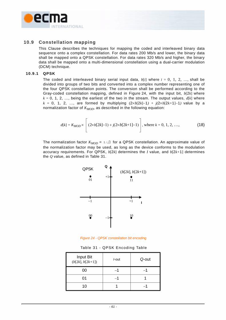
10.9 Constellation mappingThis Clause describes the techniques for mapping the coded and interleaved binary datasequence onto a complex constellation. For data rates 200 Mb/s and lower, the binary datashall be mapped onto a QPSK constellation. For data rates 320 Mb/s and higher, the binarydata shall be mapped onto a multi-dimensional constellation using a dual-carrier modulation(DCM) technique.
10.9.1 QPSKThe coded and interleaved binary serial input data, b[i] where i = 0, 1, 2, …, shall bedivided into groups of two bits and converted into a complex number representing one ofthe four QPSK constellation points. The conversion shall be performed according to theGray-coded constellation mapping, defined in Figure 24, with the input bit, b[2k] wherek = 0, 1, 2, …, being the earliest of the two in the stream. The output values, d[k] wherek = 0, 1, 2, …, are formed by multiplying (2×b[2k]−1) + j(2×b[2k+1]−1) value by anormalization factor of KMOD, as described in the following equation:
d[k] = KMOD × (2×b[2k]−1) + j(2×b[2k+1]−1) , where k = 0, 1, 2, …, (18)
The normalization factor KMOD = for a QPSK constellation. An approximate value ofthe normalization factor may be used, as long as the device conforms to the modulationaccuracy requirements. For QPSK, b[2k] determines the I value, and b[2k+1] determinesthe Q value, as defined in Table 31.
Table 31 - QPSK Encoding Table
Input Bit(b[2k], b[2k+1])
I-out Q-out
00 −1 −1
01 −1 1
10 1 −1
1 2⁄
+1−1
+1
−1
Q
I
QPSK
01 11
(b[2k], b[2k+1])
00 10
Figure 24 - QPSK constellation bit encoding
- 61 -

10.9.2 Dual-carrier modulation (DCM)The coded and interleaved binary serial input data, b[i] where i = 0, 1, 2, …, shall bedivided into groups of 200 bits and converted into 100 complex numbers using a techniquecalled dual-carrier modulation. The conversion shall be performed as follows:
1. The 200 coded bits are grouped into 50 groups of 4 bits. Each group is represented as(b[g(k)], b[g(k)+1], b[g(k) + 50], b[g(k) + 51]), where k ∈ [0, 49] and
g(k) = . (19)
2. Each group of 4 bits (b[g(k)], b[g(k)+1], b[g(k) + 50], b[g(k) + 51]) shall be mapped onto afour-dimensional constellation, as defined in Figure 25, and converted into two complexnumbers (d[k], d[k + 50]). The mapping between bits and constellation is enumerated inTable 32.
3. The complex numbers shall be normalized using a normalization factor KMOD.
The normalization factor KMOD = is used for the dual-carrier modulation. Anapproximate value of the normalization factor may be used, as long as the device conformsto the modulation accuracy requirements.
11 1 1
Table 31 - QPSK Encoding Table (concluded)
Input Bit(b[2k], b[2k+1])
I-out Q-out
2k k 0 24,[ ]∈2k 50+ k 25 49,[ ]∈⎩
⎨⎧
1 10⁄
- 62 -

+1−1
+1
−1
dQ[k]DCM
0011
(b[g(k)], b[g(k)+1], b[g(k)+50], b[g(k)+51])+3
−3
−3
0111 1011 1111
dI[k]
0010 0110 1010 1110
0001 0101 1001 1101
0000 0100 1000 1100
+3
dQ[k+50]
0110 1110 0010 1010
dI[k+50]
0100 1100 0000 1000
0111 1111 0011 1011
0101 1101 0001 1001
+1−1
+1
−1
DCM(b[g(k)], b[g(k)+1], b[g(k)+50], b[g(k)+51])
+3
−3
−3 +3
Figure 25 - DCM encoding: (a) mapping for d[k]; (b) mapping for d[k+50]
(a)
(b)
- 63 -

10.10 OFDM modulationThe discrete-time signal, sn[k], shall be created by taking the IDFT of the stream of complexvalues as follows:
sn[k] = CD,n[l]exp(j2πMD[l]k ⁄ NFFT) +
CG,n[l]exp(j2πMG[l]k ⁄ NFFT) + CP,n[l]exp(j2πMP[l]k ⁄ NFFT) , (20)
where k ∈ [0, NFFT − 1], n ∈ [Nsync, Npacket − 1], ND is the number of data subcarriers, NG is thenumber of guard subcarriers, NP is the number of pilot subcarriers, NFFT is the number of totalsubcarriers, and CD,n[l], CG,n[l], CP,n[l] are the complex numbers placed on the lth data, guard,
Table 32 - Dual-carr ier Modulat ion Encoding Table
Input Bit(b[g(k)], b[g(k)+1], b[g(k) + 50)], b[g(k) + 51])
d[k]I-out
d[k]Q-out
d[k + 50]I-out
d[k + 50]Q-out
0000 −3 −3 1 1
0001 −3 −1 1 −3
0010 −3 1 1 3
0011 −3 3 1 −1
0100 −1 −3 −3 1
0101 −1 −1 −3 −3
0110 −1 1 −3 3
0111 −1 3 −3 −1
1000 1 −3 3 1
1001 1 −1 3 −3
1010 1 1 3 3
1011 1 3 3 −1
1100 3 −3 −1 1
1101 3 −1 −1 −3
1110 3 1 −1 3
1111 3 3 −1 −1
1NFFT
-----------------
l 0=
ND
∑
l 0=
NG
∑
l 0=
NP
∑
- 64 -

and pilot subcarriers of the nth OFDM symbol, respectively. The relationship between CD,n[l]and CG,n[l], and the stream of complex values is defined in 10.10.2 and 10.10.3. The valuesfor CP,n[l] are defined in 10.10.4. The functions MD[l], MG[l], and MP[l] define a mapping fromthe indices [0, ND−1], [0, NG−1], and [0, NP−1] to the logical frequency subcarriers [−NT ⁄ 2, NT ⁄2] excluding 0, respectively. The exact definitions for the mapping functions MD[l], MG[l], andMP[l] are given below:
MD[l] = , (21)
MG[l] = , (22)
MP[l] = . (23)
The mapping of the data, pilot and guard subcarriers within an OFDM symbol is defined inFigure 26.
Finally, the discrete-time signals for the PLCP header, shdr,n[k], and the PSDU, sframe,n[k], shallbe created as follows by appending a zero-padded suffix (ZPS) to every IDFT output:
shdr,n[k] = , (24)
for n ∈ [Nsync, Nsync + Nhdr − 1], and
sframe,n[k] = , (25)
for n ∈ [Nsync + Nhdr, Npacket − 1]. The zero-padded suffix is typically used to mitigate the effectsof multi-path as well as to provide a time window or guard interval to allow the transmitter andreceiver sufficient time to switch between the different centre frequencies.
l 56– l 0=l 55– 1 l 9≤ ≤l 54– 10 l 18≤ ≤l 53– 19 l 27≤ ≤l 52– 28 l 36≤ ≤l 51– 37 l 45≤ ≤l 50– 46 l 49≤ ≤l 49– 50 l 53≤ ≤l 48– 54 l 62≤ ≤l 47– 63 l 71≤ ≤l 46– 72 l 80≤ ≤l 45– 81 l 89≤ ≤l 44– 90 l 98≤ ≤l 43– l 99=⎩
⎪⎪⎪⎪⎪⎪⎪⎪⎪⎪⎨⎪⎪⎪⎪⎪⎪⎪⎪⎪⎪⎧
61 l+– l 0NG2
------- 1–,∈
52 l+ lNG2
------- NG 1–,∈⎩⎪⎪⎨⎪⎪⎧
55– 10l + l 0 NP 1–,[ ]∈
sn k[ ] k 0 NFFT 1–,[ ]∈
0 k NFFT NSYM 1–,[ ]∈⎩⎪⎨⎪⎧
sn k[ ] k 0 NFFT 1–,[ ]∈
0 k NFFT NSYM 1–,[ ]∈⎩⎪⎨⎪⎧
- 65 -

Within the OFDM modulation process, frequency-domain spreading within a symbol andtime-domain spreading across two consecutive symbols is used to obtain further bandwidthexpansion, beyond that provided by the forward error correction code and the time-frequencycodes. Frequency-domain spreading entails transmitting the same information (complexnumber) on two separate subcarriers within the same OFDM symbol. Time-domain spreadinginvolves transmitting the same information across two consecutive OFDM symbols. Thistechnique is used to maximize frequency-diversity and to improve the performance in thepresence of other non-coordinated devices.
- 66 -

Logica
l Fre
quen
cy S
ubca
rrier
CD[0
]C
G[4
]
…
CG[0
]
-61
-57
-56
CP[
0]
-55
CD[
1]
-54
CD[9
]
-46
CP[
1]
-45
…
CD[
10]
-44
CD[1
8]
-36
CP[
2]
-35
…
CD[1
9]
-34
CD[2
7]
-26
CP[
3]
-25
…
CD[
28]
-24
CD[3
6]
-16
CP[
4]
-15
CD[3
7]
-14
…
-6
CP[
6] 56
…
CD[4
5]C
D[5
4]
-1
CD[4
9]
…
0DC
1
CD[
50] …
4
CD[5
3]
…
CP[
7]
1516
CD[
63]
14
CD[6
2]
…
CP[
8]
2526
CD[7
2]
24
CD[7
1]
…
CP[
9]
3536
CD[
81]
34
CD[8
0]
…
CP[
10]
4546
CD[9
0]
44
CD[8
9]
…
CP[
11]
5556
CD[
99]
54
CD[9
8]C
G[9
]
…
CG[
5]
5761
Fig
ure
26 -
Map
ping
from
dat
a, g
uard
and
pilo
t sub
carr
iers
to lo
gica
l fre
quen
cy s
ubca
rrie
rs
- 67 -

10.10.1 Implementation considerationsA common way to implement an inverse discrete Fourier transform is by using an inverseFast Fourier Transform (IFFT) algorithm. In this example, the logical frequency subcarriers[−NT ⁄ 2, NT ⁄ 2] shall be mapped according to Figure 27. The logical frequency subcarriers 1to 61 are mapped to the same numbered IFFT inputs, while the logical frequencysubcarriers –61 to –1 are mapped into IFFT inputs 67 to 127, respectively. The rest of theinputs, 62 to 66 and the 0 (DC) input, are set to zero. The subcarrier falling at DC (0th
subcarrier) is not used to avoid difficulties in DAC and ADC offsets and carrier feed-through in the RF chain. In Figure 27, dn indicates logical frequency subcarrier n.
10.10.2 Data subcarriersThe mapping between the stream of complex values and the data subcarriers is dependenton the portion of the PPDU and the data rate. In the following Clauses, a detailed mappingbetween the stream of complex values and the data subcarriers is provided.
10.10.2.1 Mapping for PLCP headerBoth frequency-domain and time-domain spreading techniques shall be used for thePLCP header. For this case, the stream of complex values, dhdr[k], where k = 0, 1, 2, …,shall be the sequence d[k] defined in 10.9.1 for the PLCP Header data. The streamdhdr[k] shall be grouped into sets of ND ⁄ 2 = 50 complex numbers. This group of complexvalues shall be mapped onto the lth data subcarrier of the nth OFDM symbol, CD,n[l], asfollows:
= , (26)
= , (27)
= pspread[n] × , (28)
NULL
NULLNULLNULLNULLNULL
d-61
d-2
d-1
d61
d2
d1
Freq
uenc
y-D
omai
n In
puts Tim
e-Dom
ain Outputs
127126
012
61626364
67
6566
127126
012
61626364
67
6566
Figure 27 - Input and outputs relationship of the IFFT
CD 2n, l[ ] dhdrND4
------- 2n Nsync–( ) l+×
CD 2n, lND2
-------+ dhdr* ND
4------- 2n Nsync–( )
ND2
------- 1– l–⎝ ⎠⎛ ⎞+×
CD 2n 1+, l[ ] dhdrND4
------- 2n Nsync–( ) l+×
- 68 -

= pspread[n] × , (29)
where
pspread[n] = , (30)
and where p[n] is a length 127 pseudo-random sequence, whose values are defined in
Table 33, l ∈ , n ∈ , ND is the number of data subcarriers,
Nsync is the number of symbols in the PLCP preamble and Nhdr is the number of symbolsin the PLCP header.
CD 2n 1+, lND2
-------+ dhdr* ND
4------- 2n Nsync–( )
ND2
------- 1– l–⎝ ⎠⎛ ⎞+×
p mod nNsync
2-------------– 6+ NFFT 1–,⎝ ⎠
⎛ ⎞
0ND2
------- 1–,Nsync
2-------------
Nsync Nhdr+2
------------------------------ 1–,
- 69 -
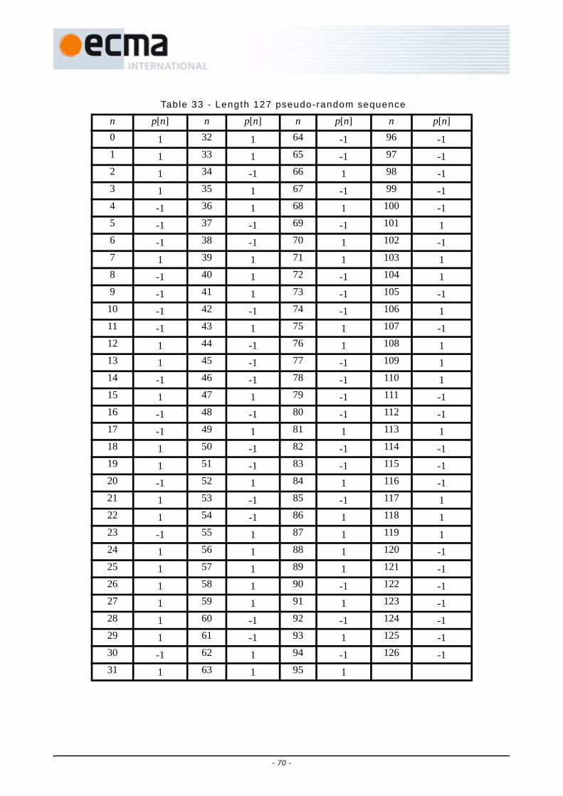
Table 33 - Length 127 pseudo-random sequence
n p[n] n p[n] n p[n] n p[n]0 1 32 1 64 -1 96 -11 1 33 1 65 -1 97 -12 1 34 -1 66 1 98 -13 1 35 1 67 -1 99 -14 -1 36 1 68 1 100 -15 -1 37 -1 69 -1 101 16 -1 38 -1 70 1 102 -17 1 39 1 71 1 103 18 -1 40 1 72 -1 104 19 -1 41 1 73 -1 105 -110 -1 42 -1 74 -1 106 111 -1 43 1 75 1 107 -112 1 44 -1 76 1 108 113 1 45 -1 77 -1 109 114 -1 46 -1 78 -1 110 115 1 47 1 79 -1 111 -116 -1 48 -1 80 -1 112 -117 -1 49 1 81 1 113 118 1 50 -1 82 -1 114 -119 1 51 -1 83 -1 115 -120 -1 52 1 84 1 116 -121 1 53 -1 85 -1 117 122 1 54 -1 86 1 118 123 -1 55 1 87 1 119 124 1 56 1 88 1 120 -125 1 57 1 89 1 121 -126 1 58 1 90 -1 122 -127 1 59 1 91 1 123 -128 1 60 -1 92 -1 124 -129 1 61 -1 93 1 125 -130 -1 62 1 94 -1 126 -131 1 63 1 95 1
- 70 -

10.10.2.2 Mapping for data rates of 53,3 Mb/s and 80 Mb/sBoth frequency-domain and time-domain spreading techniques shall be used when thePSDU is encoded at a data rate of 53,3 Mb/s or 80 Mb/s. For this case, the stream ofcomplex values, dframe[k], where k = 0, 1, 2, …, shall be the sequence defined in 10.9.1for the PSDU. The stream dframe[k] shall be grouped into sets of ND ⁄ 2 = 50 complexnumbers. This group of complex values shall be mapped onto the lth data subcarrier ofthe nth OFDM symbol, CD,n[l], as follows:
= , (31)
= , (32)
= pspread[n] × , (33)
= pspread[n] × , (34)
where pspread[n] is defined in (30), p[n] is defined in Table 33, l ∈ , n ∈
, ND is the number of data subcarriers, Nsync is the number of
symbols in the PLCP preamble, Nhdr is the number of symbols in the PLCP header andNpacket is the total number of symbols in the packet.
10.10.2.3 Mapping for data rates of 106,7 Mb/s, 160 Mb/s, and 200 Mb/sOnly time-domain spreading techniques shall be used when the PSDU is encoded at adata rate of 106,7 Mb/s, 160 Mb/s, or 200 Mb/s. For this case, the stream of complexvalues, dframe[k], where k = 0, 1, 2, …, shall be the sequence defined in 10.9.1 for thePSDU. The stream dframe[k] shall be grouped into sets of ND = 100 complex numbers.This group of complex values shall be mapped onto the lth data subcarrier of the nth
OFDM symbol, CD,n[l], as follows:
= , (35)
= pspread[n] ×
+ j , (36)
where pspread[n] is defined in (30), p[n] is defined in Table 33, l ∈ , n ∈
, ND is the number of data subcarriers, Nsync is the number of
CD 2n, l[ ] dframeND4
------- 2n Nsync– Nhdr–( ) l+×
CD 2n, lND2
-------+ dframe* ND
4------- 2n Nsync– Nhdr–( )
ND2
------- 1– l–⎝ ⎠⎛ ⎞+×
CD 2n 1+, l[ ] dframeND4
------- 2n Nsync– Nhdr–( ) l+×
CD 2n 1+, lND2
-------+ dframe* ND
4------- 2n Nsync– Nhdr–( )
ND2
------- 1– l–⎝ ⎠⎛ ⎞+×
0ND2
------- 1–,
Nsync Nhdr+2
------------------------------Npacket
2----------------- 1–,
CD 2n, l[ ] dframeND2
------- 2n Nsync– Nhdr–( ) l+×
CD 2n 1+, l[ ] dframeND2
------- 2n Nsync– Nhdr–( ) ND 1– l–( )+×⎝ ⎠⎛ ⎞imag
⎩⎨⎧
dframeND2
------- 2n Nsync– Nhdr–( ) ND 1– l–( )+×⎝ ⎠⎛ ⎞real
⎭⎬⎫
0 ND 1–,[ ]
Nsync Nhdr+2
------------------------------Npacket
2----------------- 1–,
- 71 -

symbols in the PLCP preamble, Nhdr is the number of symbols in the PLCP header andNpacket is the total number of symbols in the packet.
10.10.2.4 Mapping for data rates of 320 Mb/s, 400 Mb/s, and 480 Mb/sNo spreading techniques shall be used when the PSDU is encoded at a data rate of320 Mb/s, 400 Mb/s, or 480 Mb/s. For this case, the stream of complex values, dframe[k],where k = 0, 1, 2, …, shall be the sequence defined in 10.9.2 for the PSDU. The streamdframe[k] shall be grouped into sets of ND = 100 complex numbers. This group of complexvalues shall be mapped onto the lth data subcarrier of the nth OFDM symbol, CD,n[l], asfollows:
= , (37)
where l ∈ , n ∈ , ND is the number of data subcarriers, Nsyncis the number of symbols in the PLCP preamble, Nhdr is the number of symbols in thePLCP header and Npacket is the total number of symbols in the packet.
10.10.3 Guard subcarriersFor each OFDM symbol, starting with the channel estimation sequence within the PLCPpreamble, there shall be ten subcarriers, 5 on each edge of the occupied frequency band,allocated as guard subcarriers. The relationship between the power levels of the guardsubcarriers and that of the data subcarriers shall be implementation dependent. Thisrelationship shall remain constant within a packet, i.e., from the start of the channelestimation sequence to the end of the packet. In addition, the power levels for the guardsubcarriers shall be chosen in such a way as to ensure that the transmitted signal meetsthe local regulatory requirements of minimum occupied bandwidth and any othernecessary regulatory conditions.
The 10 guard subcarriers are located on either edge of the OFDM symbol; at logicalfrequency subcarriers -61, -60, …, -57, and 57, 58, …, 61. The data on these carriers shallbe created by copying over the five outermost data-bearing subcarriers from the nearestedge of the OFDM symbol as defined below:
= , (38)
where CG,n[l] is the lth guard subcarrier of the nth OFDM symbol, n ∈ , Nsyncis the number of symbols in the PLCP preamble and Npacket is the total number of symbolsin the packet.
Individual implementations may exploit the guard subcarriers for various purposes,including relaxing the specs on analog transmit and analog receive filters, and possiblyimproving performance.
10.10.4 Pilot subcarriersIn all of the OFDM symbols following the PLCP preamble, twelve of the subcarriers shallbe dedicated to pilot signals in order to allow for coherent detection and to providerobustness against frequency offsets and phase noise. These pilot signals shall be placedin logical frequency subcarriers -55, -45, -35, -25, -15, -5, 5, 15, 25, 35, 45, and 55. Themapping between actual pilot sequence and the pilot subcarriers is dependent on the data
CD n, l[ ] dframe ND n Nsync– Nhdr–( ) l+×[ ]
0 ND 1–,[ ] Nsync Nhdr+ Npacket 1–,[ ]
CG n, l[ ]CD n, l[ ] l 0
NG2
------- 1–,∈
CD n, l 90+[ ] lNG2
------- NG 1–,∈⎩⎪⎪⎨⎪⎪⎧
Nsync Npacket 1–,[ ]
- 72 -

portion of the PPDU and the data rate. In the following Clauses, a detailed mappingbetween the stream of complex values and the data subcarriers is provided.
10.10.4.1 Mapping for PLCP header
During the PLCP header portion of the PPDU, the information for the lth pilot subcarrierof the nth OFDM symbol shall be defined as follows:
= × dpilot,cs[l], (39)
= × pspread[n] × dpilot,cs[l], (40)
where
dpilot,cs[l] = , (41)
and where p[n] is defined in Table 33, pspread[n] is defined in (30), n ∈
, Nsync is the number of symbols in the PLCP preamble and Nhdr is
the number of symbols in the PLCP header.
10.10.4.2 Mapping for data rates of 53,3 Mb/s and 80 Mb/sWhen the PPDU is encoded at a data rate of 53,3 Mb/s or 80 Mb/s, the information forthe lth pilot subcarrier of the nth OFDM symbol shall be defined as follows:
= × dpilot,cs[l], (42)
= × pspread[n] × dpilot,cs[l], (43)
where dpilot,cs[l] is defined in (41), p[n] is defined in Table 33, pspread[n] is defined in
(30), n ∈ , Nsync is the number of symbols in the PLCP preamble,
Nhdr is the number of symbols in the PLCP header and Npacket is the total number ofsymbols in the packet.
10.10.4.3 Mapping for data rates of 106,7 Mb/s, 160 Mb/s, and 200 Mb/sWhen the PPDU is encoded at a data rate of 106,7 Mb/s, 160 Mb/s, or 200 Mb/s, theinformation for the lth pilot subcarrier of the nth OFDM symbol shall be defined as follows:
CP 2n, l[ ] p mod nNsync
2-------------– NFFT 1–,⎝ ⎠
⎛ ⎞
CP 2n 1+, l[ ] p mod nNsync
2-------------– NFFT 1–,⎝ ⎠
⎛ ⎞
1 j–2
---------- l 0 3,=
1– j+2
--------------- l 1 2 4 5, , ,=
1 j+2
----------- l 8 11,=
1– j–2
--------------- l 6 7 9 10, , ,=⎩⎪⎪⎪⎪⎪⎨⎪⎪⎪⎪⎪⎧
Nsync2
-------------Nsync Nhdr+
2------------------------------ 1–,
CP 2n, l[ ] p mod nNsync
2-------------– NFFT 1–,⎝ ⎠
⎛ ⎞
CP 2n 1+, l[ ] p mod nNsync
2-------------– NFFT 1–,⎝ ⎠
⎛ ⎞
Nsync Nhdr+2
------------------------------Npacket
2----------------- 1–,
- 73 -
= × dpilot,ncs[l], (44)
= × pspread[n] × dpilot,ncs[l], (45)
where
dpilot,ncs[l] = , (46)
and where p[n] is defined in Table 33, pspread[n] is defined in (30), n ∈
, Nsync is the number of symbols in the PLCP preamble, Nhdr is the
number of symbols in the PLCP header and Npacket is the total number of symbols in thepacket.
10.10.4.4 Mapping for data rates of 320 Mb/s, 400 Mb/s, and 480 Mb/sWhen the PPDU is encoded at a data rate of 320 Mb/s, 400 Mb/s, or 480 Mb/s, theinformation for the lth pilot subcarrier of the nth OFDM symbol shall be defined as follows:
= × dpilot,ncs[l], (47)
where dpilot,ncs[l] is defined in (46), p[n] is defined in Table 33, n ∈ ,Nsync is the number of symbols in the PLCP preamble, Nhdr is the number of symbols inthe PLCP header and Npacket is the total number of symbols in the packet.
11 General requirements
11.1 Operating band frequencies11.1.1 Operating frequency range
This PHY operates in the 3 100 − 10 600 MHz frequency band.
11.1.2 Band numberingThe relationship between centre frequency, fc, and BAND_ID number, nb, is given by thefollowing equation:
fc(nb) = . (48)
This definition provides a unique numbering system for all channels that have a spacing of528 MHz and lie within the band 3 100 − 10 600 MHz. As defined in Figure 28, six bandgroups are defined. Band groups 1 to 4 consist of 3 bands each, spanning the bands 1 to 12.
CP 2n, l[ ] p mod nNsync
2-------------– NFFT 1–,⎝ ⎠
⎛ ⎞
CP 2n 1+, l[ ] p mod nNsync
2-------------– NFFT 1–,⎝ ⎠
⎛ ⎞
1 j+2
----------- l 0 3 8 11, , ,=
1– j–2
--------------- l 1 2 4 5 6 7 9 10, , , , , , ,=⎩⎪⎪⎨⎪⎪⎧
Nsync Nhdr+2
------------------------------Npacket
2----------------- 1–,
CP n, l[ ] p mod n Nsync–Nhdr
2-----------– NFFT 1–,⎝ ⎠
⎛ ⎞
Nsync Nhdr+ Npacket 1–,[ ]
2904 528 nb MHz( )×+ nb 1 … 14, ,=
- 74 -
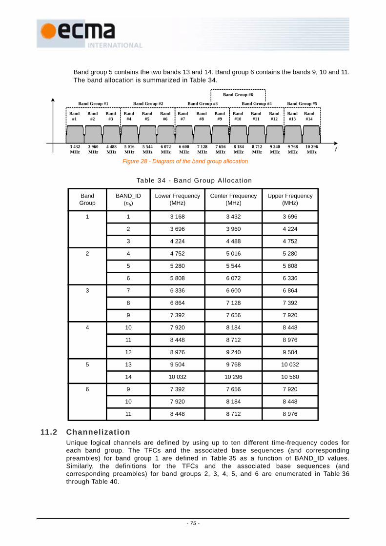
Band group 5 contains the two bands 13 and 14. Band group 6 contains the bands 9, 10 and 11.The band allocation is summarized in Table 34.
11.2 ChannelizationUnique logical channels are defined by using up to ten different time-frequency codes foreach band group. The TFCs and the associated base sequences (and correspondingpreambles) for band group 1 are defined in Table 35 as a function of BAND_ID values.Similarly, the definitions for the TFCs and the associated base sequences (andcorresponding preambles) for band groups 2, 3, 4, 5, and 6 are enumerated in Table 36through Table 40.
Table 34 - Band Group Al locat ion
Band Group
BAND_ID(nb)
Lower Frequency(MHz)
Center Frequency(MHz)
Upper Frequency(MHz)
1 1 3 168 3 432 3 696
2 3 696 3 960 4 224
3 4 224 4 488 4 752
2 4 4 752 5 016 5 280
5 5 280 5 544 5 808
6 5 808 6 072 6 336
3 7 6 336 6 600 6 864
8 6 864 7 128 7 392
9 7 392 7 656 7 920
4 10 7 920 8 184 8 448
11 8 448 8 712 8 976
12 8 976 9 240 9 504
5 13 9 504 9 768 10 032
14 10 032 10 296 10 560
6 9 7 392 7 656 7 920
10 7 920 8 184 8 448
11 8 448 8 712 8 976
Figure 28 - Diagram of the band group allocation
f3 432MHz
3 960MHz
4 488MHz
5 016MHz
5 544MHz
6 072MHz
6 600MHz
7 128MHz
7 656MHz
8 184MHz
8 712MHz
9 240MHz
9 768MHz
Band #1
Band #2
Band #3
Band #4
Band #5
Band #6
Band #7
Band #8
Band#9
Band #10
Band #11
Band #12
Band #13
10 296MHz
Band #14
Band Group #1 Band Group #2 Band Group #3 Band Group #4 Band Group #5
Band Group #6
- 75 -
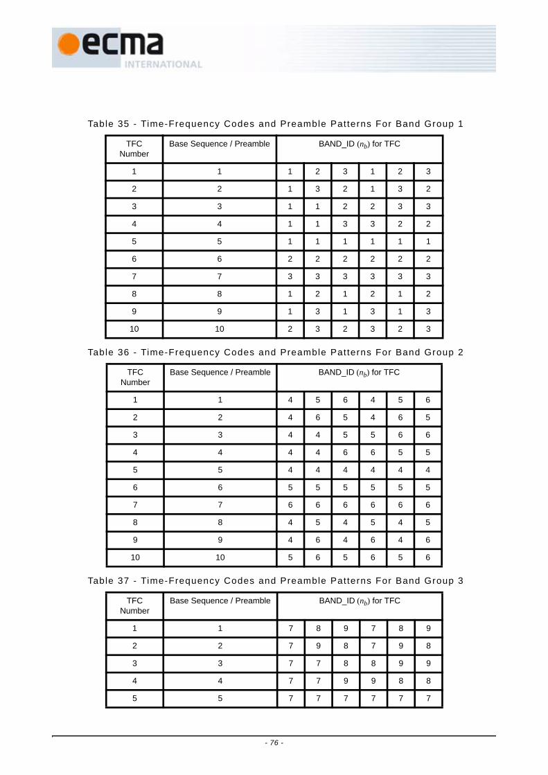
Table 35 - Time-Frequency Codes and Preamble Patterns For Band Group 1
TFC Number
Base Sequence / Preamble BAND_ID (nb) for TFC
1 1 1 2 3 1 2 3
2 2 1 3 2 1 3 2
3 3 1 1 2 2 3 3
4 4 1 1 3 3 2 2
5 5 1 1 1 1 1 1
6 6 2 2 2 2 2 2
7 7 3 3 3 3 3 3
8 8 1 2 1 2 1 2
9 9 1 3 1 3 1 3
10 10 2 3 2 3 2 3
Table 36 - Time-Frequency Codes and Preamble Patterns For Band Group 2
TFC Number
Base Sequence / Preamble BAND_ID (nb) for TFC
1 1 4 5 6 4 5 6
2 2 4 6 5 4 6 5
3 3 4 4 5 5 6 6
4 4 4 4 6 6 5 5
5 5 4 4 4 4 4 4
6 6 5 5 5 5 5 5
7 7 6 6 6 6 6 6
8 8 4 5 4 5 4 5
9 9 4 6 4 6 4 6
10 10 5 6 5 6 5 6
Table 37 - Time-Frequency Codes and Preamble Patterns For Band Group 3
TFC Number
Base Sequence / Preamble BAND_ID (nb) for TFC
1 1 7 8 9 7 8 9
2 2 7 9 8 7 9 8
3 3 7 7 8 8 9 9
4 4 7 7 9 9 8 8
5 5 7 7 7 7 7 7
- 76 -

6 6 8 8 8 8 8 8
7 7 9 9 9 9 9 9
8 8 7 8 7 8 7 8
9 9 7 9 7 9 7 9
10 10 8 9 8 9 8 9
Table 38 - Time-Frequency Codes and Preamble Patterns For Band Group 4
TFC Number
Base Sequence / Preamble BAND_ID (nb) for TFC
1 1 10 11 12 10 11 12
2 2 10 12 11 10 12 11
3 3 10 10 11 11 12 12
4 4 10 10 12 12 11 11
5 5 10 10 10 10 10 10
6 6 11 11 11 11 11 11
7 7 12 12 12 12 12 12
8 8 10 11 10 11 10 11
9 9 10 12 10 12 10 12
10 10 11 12 11 12 11 12
Table 39 - Time-Frequency Codes and Preamble Patterns For Band Group 5
TFC Number
Base Sequence / Preamble BAND_ID (nb) for TFC
5 5 13 13 13 13 13 13
6 6 14 14 14 14 14 14
8 8 13 14 13 14 13 14
Table 40 - Time-Frequency codes and preamble patterns for Band Group 6
MACTFC
Number
MACBand Group
PHY TFC
number
PHY Band Group
Base Sequence
/ Preamble
BAND_ID (nb) for TFC
1 6 1 6 3 9 10 11 9 10 11
2 6 2 6 4 9 11 10 9 11 10
3 6 3 6 1 9 9 10 10 11 11
Table 37 - Time-Frequency Codes and Preamble Patterns For Band Group 3 (concluded)
TFC Number
Base Sequence / Preamble BAND_ID (nb) for TFC
- 77 -

Band group 6 requires special consideration due to overlap with band groups 3 and 4.Referring to Table 40, the MAC TFC number and MAC BG are the ones used by the MACwhen selecting the current channel. If the MAC-PHY interface is implemented then the MACTFC number and MAC BG are used in the TXCHAN and RXCHAN registers (see ECMA-369for definitions of these registers). The MAC TFC number also indicates the hopping patternand cover sequence to be used. The PHY TFC number and the PHY BG are the valuesencoded in the PHY Header, TXVECTOR and RXVECTOR. The mapping in Table 40 ensuresthat fully overlapping channels appear identical over the air.
The PHY layer channelization scheme is based on the definition of band groups, as definedin Table 34, and the definition of TFCs, as defined in Table 35 through Table 40, and issummarized in Table 41. The PHY channels are identified by channel numbers as defined inthis table. The channel number takes on values from 0−255 (decimal). The values not definedin Table 41 are reserved for future use. Channels using TFCs 1−4 are also referred to astime-frequency interleaved (TFI) channels, and those using TFCs 5−7 are also referred to asfixed-frequency interleaved (FFI) channels. Channels using TFCs 8-10 are referred to as two-band time-frequency interleaved (TFI2) channels.
4 6 4 6 2 9 9 11 11 10 10
5 6 7 3 7 9 9 9 9 9 9
6 6 5 4 5 10 10 10 10 10 10
7 6 6 4 6 11 11 11 11 11 11
8 6 9 6 9 9 10 9 10 9 10
9 6 10 6 10 9 11 9 11 9 11
10 6 8 4 8 10 11 10 11 10 11
Table 41 - Mapping of Channel Number to Band Group and Time-Frequency Code
ChannelNumber(decimal)
ChannelNumber(octal)
(Band Group, TF Code)
9 - 15 011 - 017 (1, 1 - 7)
17 - 23 021 - 027 (2, 1 - 7)
25 - 31 031 - 037 (3, 1 - 7)
33 - 39 041 - 047 (4, 1 - 7)
45 - 46 055 - 056 (5, 5 - 6)
49 - 55 061 - 067 (6, 1 - 7)
72 - 74 110 - 112 (1, 8 - 10)
80 - 82 120 - 122 (2, 8-10)
Table 40 - Time-Frequency codes and preamble patterns for Band Group 6 (concluded)
MACTFC
Number
MACBand Group
PHY TFC
number
PHY Band Group
Base Sequence
/ Preamble
BAND_ID (nb) for TFC
- 78 -

A band group is supported if all channels in the band group are supported.
For band group 6, the Band Group and TFC in Table 41 indicate the MAC Band Group andMAC TFC.
The current channel number for transmit or receive indicates an intended band group, whichin turn indicates the use of bits in the Tone-Nulling mask.
11.3 PHY layer timingThe values for the PHY layer timing parameters are defined in Table 42.
11.3.1 Interframe spacingThe interframe spacing parameters are given in Table 43.
11.3.2 Receive-to-transmit turnaround t imeThe RX-to-TX turnaround time shall not be greater than pSIFS. This turnaround time shallbe measured at the air interface. The time elapsed from the leading edge of the lastreceived symbol, where a symbol is composed of the OFDM symbol (IFFT output) and azero-padded suffix, to the leading edge of the first transmitted symbol of the PLCPpreamble for the next frame shall not be greater than pSIFS + TSYM.
88 - 90 130 - 132 (3, 8-10)
96 - 98 140 - 142 (4, 8-10)
104 150 (5, 8)
112 - 114 160 - 162 (6, 8-10)
Table 42 - PHY layer t iming parameters
PHY Parameter Value
pMIFS 6 × TSYM = 1,875 μs
pSIFS 32 × TSYM = 10,0 μs
pCCADetectTime 18 × TSYM = 5,625 μs
pBandSwitchTime 9,47 ns
Table 43 - Inter f rame spacing parameters
MAC Parameter Value
MIFS pMIFS
SIFS pSIFS
Table 41 - Mapping of Channel Number to Band Group and Time-Frequency Code (concluded)
ChannelNumber(decimal)
ChannelNumber(octal)
(Band Group, TF Code)
- 79 -
11.3.3 Transmit-to-receive turnaround t imeThe TX-to-RX turnaround time shall not be greater than pSIFS. This turnaround time shallbe measured at the air interface. The time elapsed from the leading edge of the lasttransmitted symbol until the receiver is ready to begin the reception of the next PHY frameshall not be greater than pSIFS + TSYM.
11.3.4 Time between successive transmissionsFor uninterrupted successive transmissions by a device in standard mode, the interframespacing after the packet shall be pSIFS if PLCP length field is zero, and shall not be lessthan pMIFS if the PLCP length field is non-zero. The interframe spacing time shall bemeasured at the air interface. When the PLCP length field is zero, the time elapsed fromthe leading edge of the last transmitted symbol to the leading edge of the first transmittedsymbol of the PLCP preamble for the following packet shall be equal to pSIFS + TSYM.When the PLCP length field is non-zero, the time elapsed from the leading edge of the lasttransmitted symbol to the leading edge of the first transmitted symbol of the PLCPpreamble for the following packet shall not be less than pMIFS + TSYM.
For burst mode transmissions, the interframe spacing between uninterrupted successivetransmissions by a device shall be fixed to pMIFS ±1 ns. The interframe spacing time shallbe measured at the air interface. The time elapsed from the leading edge of the lasttransmitted symbol to the leading edge of the first transmitted symbol of the PLCPpreamble for the following packet shall be fixed to pMIFS + TSYM ±1 ns.
See 10.3.1.4 for details on LENGTH constraints for burst mode.
11.3.5 Band frequency switch t imeThe band frequency switch time is defined as the interval from when the PHY receives thelast valid sample of a symbol on one band frequency until it is ready to receive the nextsymbol on a new band frequency. For best performance, the switching time between bandfrequencies should not exceed pBandSwitchTime.
12 Transmitter specifications
12.1 Transmit PSD maskThe transmitted spectral mask shall have the following break points: an emissions level of0 dBr (dB relative to the maximum spectral density of the signal) from −260 MHz to 260 MHzaround the centre frequency, −12 dBr at 285 MHz frequency offset, and −20 dBr at 330 MHzfrequency offset and above. For all other intermediate frequencies, the emissions level isassumed to be linear in the dB scale. The transmitted spectral density of the transmittedsignal shall fall within the spectral mask, as defined in Figure 29.
- 80 -

12.2 Transmit centre frequency toleranceThe transmitted centre frequency tolerance shall be ±20 ppm maximum.
12.3 Symbol clock frequency toleranceThe symbol clock frequency tolerance shall be ±20 ppm maximum.
12.4 Clock synchronizationThe transmit centre frequencies and the symbol clock frequency shall be derived from thesame reference oscillator.
12.5 Phase coherenceThe transmit carrier frequencies shall be phase coherent within a single band over theduration of a single packet. Lack of phase coherence may contribute to TransmitterConstellation Error as described in 12.7.
Phase coherence in TFI mode or TFI2 mode means that the phase of the LO is coherentwhen it returns to the same frequency. For example, let ωk = radian frequency and θk=phase,k={1,2,3}. The LO can be represented as sin(ωkt + θk). Let the hopping pattern be1,2,3,1,2,3,... Frequency hops occur when t = NT, T=symbol duration. Thus at the hoppingpoints, the LO is sin(ω1T + θ1), sin(ω22T + θ2), sin(ω33T + θ3), sin(ω14T + θ1), sin(ω25T + θ2),sin(ω36T + θ3),... which is phase coherent by definition since the LO returns to the samephase θ1 for N=1,4,...; θ2 for N=2,5,...; θ3 for N=3,6,...
12.6 Transmit power controlA device shall provide support for transmit power control (TPC). The objective of a powercontrol algorithm is to minimize the transmit power spectral density, while still providing areliable link for the transfer of information.
Figure 29 - Transmit power spectral density mask
- 81 -

When the device is using time-frequency interleaving, the monotonic dynamic range for theattenuation of the transmit power shall be 0 – 12 dB, with a step size granularity of 2 dB.When the device is using time-frequency interleaving over 2 bands, the monotonic dynamicrange for the attenuation of the transmit power shall be 0 – 10 dB, with a step size granularityof 2 dB. When the device is using fixed-frequency interleaving, the monotonic dynamicrange for the attenuation of the transmit power shall be 0 – 8 dB, with a step sizegranularity of 2 dB. Table 44 summaries the mapping between the TXPWR_LEVEL and theassociated transmit power attenuation.
In either case, the relative accuracy of change in transmit power attentuation shall be themaximum of ±1 dB or ±20% of the change in the attenuation (in the dB scale). As anexample, for an attenuation change of 4 dB and an attenuation change of 8 dB, the allowedrelative accuracy is ±1,0 dB and ±1,6 dB, respectively.
Finally, the device shall support a value for the signal-to-carrier leakage at transmitter outputport of at least 20 dB.
12.7 Transmitter constellation errorThe relative constellation RMS error, averaged over all data and pilot subcarriers of theOFDM symbols and over all of the frames, shall not exceed the values given in Table 45.Note that the relative constellation error values are a function of the transmit powerattenuation. The relative constellation error values are based on a multi-path margin of2,5 dB for data rates of 200 Mb/s and lower and 3,6 dB for data rates 320 Mb/s and higher,and an implementation loss of 2,5 dB. In addition, it is assumed that the degradation due tothe relative constellation error can be no more than 0,5 dB for data rates of 200 Mb/s andlower, and 1,0 dB for data rates of 320 Mb/s and higher.
Table 44 - Mapping between TXPWR_LEVEL and transmit power at tenuat ion
TXPWR_LEVEL TX Power Attenuationfor TFI Modes
TX Power Attenuationfor TFI2 Modes
TX Power Attenuationfor FFI Modes
0 0 dB 0 dB 0 dB
1 2 dB 2 dB 2 dB
2 4 dB 4 dB 4 dB
3 6 dB 6 dB 6 dB
4 8 dB 8 dB 8 dB
5 10 dB 10 dB RESERVED
6 12 dB RESERVED RESERVED
7 RESERVED RESERVED RESERVED
- 82 -

The relative constellation RMS error calculation shall be performed using a device capable ofconverting the transmitted signal into a stream of complex samples at 528 Msample/s ormore, with sufficient accuracy in the I/Q imbalance, DC offset, phase noise, etc. The sampledsignal shall then be processed in a manner similar to that of an ideal receiver includingadding the first 32 samples of the zero-padded suffix to the received OFDM symbol via theoverlap-and-add method. An example of the minimum steps necessary for receiverprocessing is listed below:
1. Detect the start of the packet and frame boundary.
2. Estimate the correct sampling time and frequency offset. Correct as needed.
3. Estimate the channel frequency response.
4. For each symbol estimate the common phase error (CPE) from the pilot sub-carriers, then filterthe sequence of CPE estimates using a single-pole low-pass filter with a 3 dB cut-off frequencyas defined in Table 46. De-rotate each OFDM symbol with the filtered phase estimate.
2π corresponds to the filter update rate of FSYM for FFI Modes, FSYM/3 for TFI Modes and FSYM/2 forTFI2 Modes. The value for FSYM is defined in Table 2.
5. Equalize the channel with the estimated channel frequency response.
6. For each of the data and pilot subcarriers, find the closest constellation point and compute theEuclidean distance.
7. Compute the RMS error, averaged over all the data and pilot subcarriers and over all frames, asfollows:
Table 45 - Permissib le Relat ive Conste l lat ion Error
Relative Constellation RMS Error
Data Rate No TX AttenuationTX Attenuation of
2, 4, 6 dB(All TFCs)
TX Attenuation of8, 10, 12 dB(All TFCs)
53,3 Mb/s, 80 Mb/s,106,7 Mb/s, 160 Mb/s,
200 Mb/s
−17,0 dB -15,5 dB -14,5 dB
320 Mb/s, 400 Mb/s,480 Mb/s
−19,5 dB -18,0 dB -17,0 dB
Table 46 - CPE measurement 3 dB cut-off f requency
3 dB cutoff frequency (radians/filter update rate) TFC number
π/4 1, 2, 3, 4
π/12 5, 6, 7
π/6 8, 9, 10
- 83 -
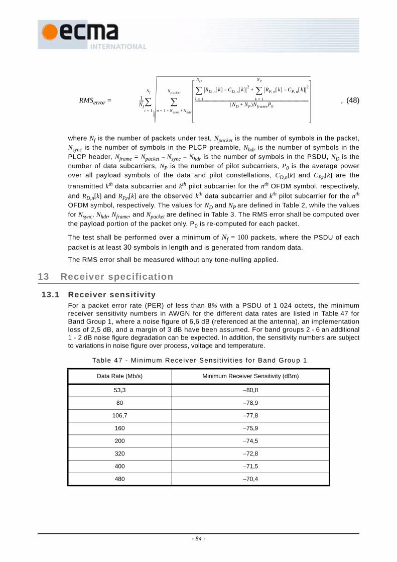
RMSerror = , (48)
where Nf is the number of packets under test, Npacket is the number of symbols in the packet,Nsync is the number of symbols in the PLCP preamble, Nhdr is the number of symbols in thePLCP header, Nframe = Npacket − Nsync − Nhdr is the number of symbols in the PSDU, ND is thenumber of data subcarriers, NP is the number of pilot subcarriers, P0 is the average powerover all payload symbols of the data and pilot constellations, CD,n[k] and CP,n[k] are thetransmitted kth data subcarrier and kth pilot subcarrier for the nth OFDM symbol, respectively,and RD,n[k] and RP,n[k] are the observed kth data subcarrier and kth pilot subcarrier for the nth
OFDM symbol, respectively. The values for ND and NP are defined in Table 2, while the valuesfor Nsync, Nhdr, Nframe, and Npacket are defined in Table 3. The RMS error shall be computed overthe payload portion of the packet only. P0 is re-computed for each packet.
The test shall be performed over a minimum of Nf = 100 packets, where the PSDU of eachpacket is at least 30 symbols in length and is generated from random data.
The RMS error shall be measured without any tone-nulling applied.
13 Receiver specification
13.1 Receiver sensitivityFor a packet error rate (PER) of less than 8% with a PSDU of 1 024 octets, the minimumreceiver sensitivity numbers in AWGN for the different data rates are listed in Table 47 forBand Group 1, where a noise figure of 6,6 dB (referenced at the antenna), an implementationloss of 2,5 dB, and a margin of 3 dB have been assumed. For band groups 2 - 6 an additional1 - 2 dB noise figure degradation can be expected. In addition, the sensitivity numbers are subjectto variations in noise figure over process, voltage and temperature.
Table 47 - Min imum Receiver Sensi t iv i t ies for Band Group 1
Data Rate (Mb/s) Minimum Receiver Sensitivity (dBm)
53,3 −80,8
80 −78,9
106,7 −77,8
160 −75,9
200 −74,5
320 −72,8
400 −71,5
480 −70,4
1Nf-----
RD n, k[ ] CD n, k[ ]– 2
k 1=
ND
∑ RP n, k[ ] CP n, k[ ]– 2
k 1=
NP
∑+
ND NP+( )NframeP0--------------------------------------------------------------------------------------------------------------------------------
n 1 Nsync Nhdr+ +=
Npacket
∑i 1=
Nf
∑
- 84 -

13.2 Receiver CCA performanceThe start of a valid OFDM transmission at a receiver level equal to or greater than theminimum sensitivity for a 53,3 Mb/s transmission (−80,8 dBm) shall cause CCA to indicatethat the channel is busy with a probability > 90% within pCCADetectTime.
13.3 Link quality indicatorA device shall be capable of estimating the link quality of the received channel, where the linkquality shall be defined as an estimate of the SNR available after the FFT and will include allimplementation losses associated with that particular receiver architecture (quantizationnoise, channel estimation errors, etc.). Devices capable only of data rates up to 200Mbpsshall be capable of estimating values in the range from -2 dB to +7 dB. Devices capable ofdata rates above 200Mbps shall be capable of estimating values in the range from –2 dB to +12 dB.Estimating values below –2 dB or above +12 dB is optional. All estimated values, whenmeasured under static channel conditions, shall be monotonically increasing with signalstrength over the entire reporting range. Note that the estimates may exhibit saturationbehaviour at values higher than +12 dB. Finally, the link quality estimates shall be made on apacket-by-packet basis.
When reporting the estimates of the link quality, the device shall quantize these values to thenearest dB in the range from –6 dB to +24 dB and report them as the link quality estimate(LQE). The accuracy of the LQE is defined as the standard deviation of the packet-by-packetestimates for a static AWGN channel and a fixed SNR value. Table 48 enumerates theallowed standard deviation of the estimates as a function of the reporting range. Even thoughthe reported estimates should be nominally equal to the SNR after the FFT, no bounds onabsolute accuracy with respect to an external reference plane are intended or implied by thisspecification.
The mapping between LQE and the Link Quality Indicator (LQI) is summarized in Table 49. AStandard encoding is used to report the estimates in the range from –6 dB (0000 0001) to+24 dB (0001 1111). The all-ZERO bit representation implies that reporting of LQE is notsupported by the device, or that LQE is too small to be measured accurately. Additionally, therange from 1000 0000 to 1011 1111 and the range from 1100 0000 to 1111 1111 are defined toallow vendors to report additional link quality information. All other bit representations arereserved for future use.
The test for the accuracy of the link quality estimate shall be performed over a minimum ofNf = 1 000 packets, where the PSDU of each packet is at least 1 024 bytes in length and isgenerated from random data.
Table 48 - Al lowed Standard Deviat ion for the LQE with a payload of 1 024 Bytes
Link Quality Estimate (LQE) Standard Deviation for Estimate (σ)
-6 dB, …, -4 dB 1,3 dB
-3 dB, …, 0 dB 1,1 dB
1 dB, …, 6 dB 0,9 dB
7 dB, …, 24 dB 0,7 dB
Table 49 - Encoding for the L ink Qual i ty Est imates
LQI Description
0000 0000 Link Quality is too low to be measured
- 85 -

13.4 Receive Signal Strength IndicatorA device may indicate the strength in decibels of the incoming signal. The RSSI is amonotonically increasing function of the energy received at the antenna. It is a value between0 and RSSIMaximum. RSSIMaximum is implementation defined, up to 255.
14 Ranging and location awareness
A device may support the capability to determine the round trip delay between itself and anotherdevice, hereafter referred to as ranging. This round trip delay may be used to calculate thedistance between the devices. The distance can be estimated by multiplying the speed of lightby the measured propagation delay between the devices.
14.1 Ranging requirementsIf ranging is supported, all devices shall support ranging capabilities with an accuracy andprecision of ±60 cm or better.
14.2 Ranging reference signalThe propagation delay between two devices should be measured with respect to a referencepoint. The ranging reference point is the beginning of the first channel estimation symbol inthe PLCP preamble, i.e., the first sample of the first channel estimation sequence
(see 10.2.1, Figure 7, Figure 8 and (4)).
14.3 PHY ranging resourcesIf ranging is supported, the PHY shall contain a MIB attribute pRangingTimer to capture thetime of generation or detection of the ranging reference signal. This attribute captures thevalue of a 15-bit to 32-bit ranging counter which is running at the clock frequency specified inTable 59. See Table 59 for a list of valid ranging timer configurations.
If ranging is supported, implementations shall support at least a pRangingTimer containingthe value of a 15-bit counter in the Active Timer Bits [17:3] clocked at 528 MHz. Bits [31:18] and[2:0] shall be ZERO.
Implementations may provide more timer bits and higher clock frequencies to increaseprecision as described in 2.4.
To support MAC algorithms that use multiple ranging transactions to correct for frequencyoffset between two stations, longer counters may be provided in PHY hardware. If supportedin the PHY, more of the bits [31:18] will be active. All inactive bits shall be ZERO.
14.4 PHY ranging operationIf ranging is supported, the PHY shall set the pRangingTimer to the ranging counter valuewhen either of the following occurs:
• PHY is in transmit mode, and the PHY reaches the ranging reference point.
0000 0001 – 0001 1111 LQI = (LQE + 7dB)
0010 0000 – 0111 1111 RESERVED
1000 0000 – 1011 1111 Vendor specific Link Quality encoding
1100 0000 – 1111 1111 Vendor specific Link Quality encoding
Table 49 - Encoding for the Link Qual i ty Est imates (concluded)
LQI Description
ssync Npf, 0[ ]
- 86 -

• PHY is in receive mode, and the PHY recognizes the ranging reference point
14.5 Ranging calibration constantsIf ranging is supported, the following constants shall be made available. These values allowthe MAC to correct the pRangingTimer values for delays in the PHY and associated circuits.
1 RANGING_TRANSMIT_DELAY = the time from the PHY sampling the ranging countercorresponding to its processing the ranging reference point to the time that ranging referencepoint is emitted from the local antenna.
2 RANGING_RECEIVE_DELAY = the time from the arrival of the ranging reference point at thelocal antenna to the time that ranging reference point is first recognised in the PHY,corresponding to its sampling the ranging counter.
These constants are 16-bit unsigned integer values, in units of 4 224 MHz clock periods.These values allow the MAC to correct the pRangingTimer values for delays in the PHY andassociated circuits.
14.6 Example range measurement (informative)Figure 30 shows a pair of ranging frames being exchanged between two devices. RM1 isdesignated as the initial ranging measurement frame transmitted by device #1, whereas RM2is designated as the reply ranging measurement frame transmitted by device #2. Each devicemust take two measurements: one when the ranging measurement frame is sent (Ti, wherei = 1, 2), and one when the ranging measurement frame is received (Ri, where i = 1, 2). Next,each device must apply the ranging calibration constants (see 14.5) to account for signalprocessing delays through the transmit and receive chains:
Tic = Ti + RANGING_TRANSMIT_DELAY, (49)
Ric = Ri − RANGING_RECEIVE_DELAY, (50)
where i = 1, 2 and where Tic and Ric are the calibrated time measurements. Finally, device #2must deliver the measurement values T2c and R2c to device #1.
- 87 -

Given the four compensated time measurements, a simple range estimate, D, can becalculated as follows:
D = c × , (51)
where c is the speed of light.
15 PHY and MAC service access points (informative)
This informative clause presents one conceptual interface to illustrate the functionality of adevice that implements this specification. It is not intended for physical implementation or as acomputer language interface.
Service access points (SAPs) are provided for data transfer and for management of thephysical (PHY) layer and medium access control (MAC) sublayer.
The reference model in Figure 31 illustrates the logical entities and the relationships betweenthem.
All SAPs are logical interfaces and do not necessarily imply a particular implementation or anexposed interface.
The PHY provides data services to the MAC sublayer through the PHY service access point(SAP). These services are described in this Clause in terms of PHY primitives exchangedbetween the MAC and the PHY via the PHY SAP.
t
Preamble Header Payload
Preamble Header Payload
Device #1
Device #2
Propagation Time
T1c
R2c
RM1
Preamble Header Payload
Preamble Header Payload
Propagation Time
T2c
R1c
RM2
Figure 30 - Example ranging measurement frame pair
R2c T1c–( ) T2c R1c–( )–
2--------------------------------------------------------------
- 88 -

The MAC provides data services to the MAC client through the MAC SAP. These services aredescribed in this Clause in terms of MAC primitives exchanged between the MAC and the MACclient via the MAC SAP.
Both the MAC sublayer and the PHY layer conceptually include management entities, called theMAC sublayer management entity (MLME) and physical layer management entity (PLME).These entities provide the layer management service interfaces for the layer managementfunctions. For management of the MAC and PHY, a device management entity (DME) should bepresent within each device. The PLME and MLME provide management services to the DMEthrough the PLME and MLME SAPs. The DME is a layer-independent entity that may be viewedas residing in a separate management plane or as residing "off to the side." The DME is outsidethe scope of this Standard, but this entity may be viewed as being responsible for suchfunctions as the gathering of layer-dependent status from the various layer managemententities and similarly setting the value of layer-specific parameters. The DME typically performssuch functions on behalf of the general system management entities and implements Standardmanagement protocols
.
15.1 Generic MIB management primitivesThe management information specific to the PHY layer or the MAC sublayer is represented ina management information base (MIB). Devices are not intended to be managed across anetwork. Devices use the management information to ascertain and control certaincharacteristics of the PHY layer and MAC sublayer.
The management entity is viewed as "containing" the MIB. The MIB-related managementprimitives exchanged across the management SAP allow the DME to either "GET" the valueof a MIB attribute, or to "SET" the value of a MIB attribute. The invocation of a SET.requestprimitive may require the PHY layer or the MAC sublayer to perform defined actions.
The GET and SET primitives are represented as requests with associated confirm primitives.
Figure 31 - The SAP reference model used in this Standard
M e d iu m a c c e s s c o n tro l (M A C )
s u b la y e r
M A C s u b la y e r m a n a g e m e n t e n tity (M L M E )
P H Y la y e rP h y s ic a l la y e r m a n a g e m e n t e n tity (P L M E )
D e v ic e m a n a g e m e n t e n tity (D M E )
M A C c lie n t
MAC
PHY
MLM
E S
APP
LME
SAP
P H Y S A P
M A C S A P
- 89 -

The primitives for the PHY layer management SAP are prefixed by PLME and for the MACsublayer are prefixed by MLME. XX in the table and following Clauses denotes MLME orPLME. The primitives are summarized in Table 50.
The parameters used for these primitives are defined in Table 51.
15.1.1 XX-GET.requestThis primitive requests information about a given attribute. The definition of this primitiveis:
XX-GET.request(
MIBattribute)
The primitive parameter is defined in Table 51.
15.1.1.1 When generatedThis primitive is generated by the DME to obtain information from the PHY or MAC.
15.1.1.2 Effect of receiptThe PLME or MLME attempts to retrieve the requested PHY or MAC attribute from itsdatabase and responds with XX-GET.confirm that gives the result.
15.1.2 XX-GET.confirmThis primitive reports the results of an information request about the PHY or MAC. Thedefinition of this primitive is:
XX-GET.confirm(
ResultCode,MIBattribute,MIBvalue)
The primitive parameters are defined in Table 51.
Table 50 - Summary of gener ic management pr imit ives
Name Request Confirm
XX-GET 15.1.1 15.1.2
XX-SET 15.1.3 15.1.4
Table 51- Gener ic management pr imit ive parameters
Name Type Valid range Description
MIBattribute Octet string Any MIB attribute as defined in 15.3 or 15.5
The name of the MIB attribute
MIBvalue Variable As defined in 15.3 or 15.5 The value of the MIB attribute
ResultCode Enumeration SUCCESS, INVALID_MIB_ATTRIBUTE_NAME, INVALID_MIB_ATTRIBUTE_VALUE, READ_ONLY_MIB_ATTRIBUTE, WRITE_ONLY_MIB_ATTRIBUTE
Indicates the result of the PLME or MLME request
- 90 -

15.1.2.1 When generatedThis primitive is generated in response to an XX-GET.request by the DME.
15.1.2.2 Effect of receiptThe primitive returns the appropriate MIB attribute value if the ResultCode is SUCCESS;otherwise it returns an error indication in the ResultCode. Possible values of theResultCode that would indicate an error are INVALID_MIB_ATTRIBUTE_NAME andWRITE_ONLY_MIB_ATTRIBUTE.
15.1.3 XX-SET.requestThis primitive attempts to set the indicated MIB attribute to the given value. The definitionof this primitive is:
XX-SET.request(
MIBattribute,MIBvalue)
The primitive parameters are defined in Table 51.
15.1.3.1 When generatedThis primitive is generated by the DME to set the indicated MIB attribute.
15.1.3.2 Effect of receiptThe PLME or MLME attempts to set the requested MIB attribute in its database. If thisMIB attribute implies a specific action, then this requests that the action be performed.The PLME or MLME responds with XX-SET.confirm that gives the result.
15.1.4 XX-SET.confirmThis primitive reports the results of an attempt to set the value of an attribute in the MIB.The definition of this primitive is:
XX-SET.confirm(
ResultCode,MIBattribute)
The primitive parameters are defined in Table 51.
15.1.4.1 When generatedThis primitive is generated in response to an XX-SET.request by the DME.
15.1.4.2 Effect of receiptIf the ResultCode is SUCCESS, this confirms that the indicated MIB attribute was set tothe requested value; otherwise it returns an error condition in the ResultCode. If thisMIBattribute implies a specific action, then this confirms that the action was performed.Possible ResultCodes for an error are:
- INVALID_MIB_ATTRIBUTE_NAME
- INVALID_MIB_ATTRIBUTE_VALUE
- READ_ONLY_MIB_ATTRIBUTE
- 91 -

15.2 PHY SAP interfaceTable 52 lists the PHY SAP primitives for peer-to-peer interactions. Table 53 lists the PHYSAP primitives for sublayer-to-sublayer interactions only.
The remainder of this sub-clause describes the services provided using these PHYprimitives.
15.2.1 Data transferThis mechanism supports the procedure of transferring an octet of data from the MACsublayer to the PHY layer or vice versa. Table 54 lists the parameters that appear in theprimitives of this Clause.
15.2.1.1 PHY-DATA.requestThis primitive requests the transfer of an octet of data from the MAC to the PHY. Thedefinition of this primitive is as follows:
PHY-DATA.request(
DATA)
15.2.1.1.1 When generatedThis primitive is generated by the MAC to request the transfer of a single octet of datafrom the MAC to the PHY. It may only be issued following a transmit initializationconfirmation (PHY-TX-START.confirm) from the PHY.
Table 52 - PHY-SAP Peer- to-Peer Service Pr imit ives
Primitive Request Indication Response Confirm
PHY-DATA × × × ×
Table 53 - PHY-SAP Sublayer- to-Sublayer Service Pr imit ives
Primitive Request Indication Response Confirm
PHY-TX-START × ×
PHY-TX-END × ×
PHY-CCA-START × ×
PHY-CCA-END × ×
PHY-RX-START × × ×
PHY-RX-END × × ×
Table 54 - PHY-DATA Pr imit ive Parameters
Name Type Valid Range Description
DATA Bit String 0x00 - 0xFF Appears in PHY-DATA.request and PHY-DATA.indication; specifies an octet of bit
string for transfer from the MAC to the PHY or vice versa.
- 92 -

15.2.1.1.2 Effect of receiptThe PHY transfers a single octet of data from the MAC. It subsequently issues a PHY-DATA.confirm to the MAC.
15.2.1.2 PHY-DATA.confirmThis primitive reports the transfer of an octet of data from the MAC to the PHY. Thedefinition of this primitive is as follows:
PHY-DATA.confirm(
)
15.2.1.2.1 When generatedThe primitive is generated by the PHY following the transfer of an octet of data fromthe MAC to the PHY.
15.2.1.2.2 Effect of receiptThe MAC generates the next PHY-DATA.request to transfer the next octet of data tothe PHY, if applicable.
15.2.1.3 PHY-DATA.indicationThis primitive indicates a transfer of an octet of data from the PHY to the MAC. Thedefinition of this primitive is as follows:
PHY-DATA.indication(
DATA)
15.2.1.3.1 When generatedThis primitive is generated by a receiving PHY layer to transfer an octet of availabledata to the local MAC sublayer. It may only be issued following a receive initializationconfirmation (PHY-RX-START.confirm) from the PHY.
15.2.1.3.2 Effect of receiptThe MAC transfers a single octet of data from the PHY. It subsequently issues a PHY-DATA.response to the PHY.
15.2.1.4 PHY-DATA.responseThis primitive responds to the transfer of an octet of data from the PHY to the MAC. Thedefinition of this primitive is as follows:
PHY-DATA.response(
)
15.2.1.4.1 When generatedThe primitive is generated by the MAC to respond to the PHY after an octet of datahas been transferred from the PHY to the MAC.
15.2.1.4.2 Effect of receiptThe PHY will generate the next PHY-DATA.indication for the transfer of the nextavailable octet of data to the MAC, if applicable.
15.2.2 PHY transmission controlThis mechanism supports the procedure of controlling the start or end of a PHYtransmission. Table 55 lists the parameters that appear in the primitives of this Clause viaTXVECTOR.
- 93 -

15.2.2.1 PHY-TX-START.requestThis primitive requests the local PHY layer to start the transmission of a PPDU onto thewireless medium. The definition of this primitive is as follows:
PHY-TX-START.request(
TXVECTOR)
Table 55 - TXVECTOR Parameters
Name Type Valid Range Description
LENGTH Integer 0 .. pMaxFramePayloadSize for standard mode;
1 .. pMaxFramePayloadSize for burst mode
Specifies the number of octets in the frame payload (which does not include the FCS, tail bits, and pad bits) that the MAC is requesting the PHY to transmit.
RATE Bit String 5 bits Specifies the data rate at which the frame body is to be transmitted (see Table 24).
BURST_MODE Enumeration ZERO = Standard Mode;
ONE = Burst Mode
Indicates whether the transmission is in the middle of a burst, i.e., whether the current PPDU will be followed by another PPDU transmitted by this device with a MIFS separation.
PREAMBLE_TYPE Enumeration ZERO = Standard Preamble;
ONE = Burst Preamble
Specifies the type of preamble for the next PPDU when BURSTMODE is set to ONE; Reserved when BURSTMODE is set to ZERO.
SCRAMBLER Bit String 2 bits Provides a 2-bit value to initialize the scrambler for the current PPDU transmission (see Table 29).
TXPWR_LEVEL Integer 0 - 7 Specifies a transmit power attenuation for the current PPDU transmission (see Table 44).
TX_TFC Bit String 4 bits Specifies the TFC code used for transmission of the current packet (see Table 27).
BG Bit String 3 bits Specifies the Band Group used for transmission of the current packet (see Table 28).
MAC_HEADER Octet String 10 octets Provides the MAC header for the current PPDU for transmission.
TN Bit String 384 bits Specifies nulled frequency carriers (see 9.2)
- 94 -

15.2.2.1.1 When generatedThe primitive is generated by the MAC sublayer to initiate the transmission of a PPDUby the local PHY layer onto the wireless medium.
15.2.2.1.2 Effect of receiptThe PHY begins transmitting a PLCP preamble. It subsequently issues a PHY-TX-START.confirm to the MAC.
15.2.2.2 PHY-TX-START.confirmThis primitive reports the start of the PLCP preamble transmission by the PHY. Thedefinition of this primitive is as follows:
PHY-TX-START.confirm(
)
15.2.2.2.1 When generatedThis primitive is generated by the PHY to indicate to the MAC the start of transmissionof the PPDU onto the wireless medium.
15.2.2.2.2 Effect of receiptThe MAC proceeds to issue PHY-DATA.request primitives to transfer the TXVECTORand frame body, if any, to the PHY when they are available, or to issue a PHY-TX-END.request primitive to end PHY’s transmission.
15.2.2.3 PHY-TX-END.requestThis primitive requests the local PHY layer to end the transmission. The definition of thisprimitive is as follows:
PHY-TX-END.request(
)
15.2.2.3.1 When generatedThis primitive is generated by the MAC following reception of the last PHY-DATA.confirm from the PHY for the current MPDU transfer.
15.2.2.3.2 Effect of receiptThe PHY stops the transmission and subsequently issues a PHY-TX-END.confirm tothe MAC.
15.2.2.4 PHY-TX-END.confirmThis primitive reports the PHY’s exit from the transmission. The definition of thisprimitive is as follows:
PHY-TX-END.confirm(
)
15.2.2.4.1 When generatedThis primitive is generated by the PHY upon stopping the local transmission.
15.2.2.4.2 Effect of receiptThe MAC is in a position to initiate the next transmit, receiver, or power managementoperation.
15.2.3 PHY reception controlThis mechanism supports the procedure of controlling the start or end of a PHY reception.Table 56 lists the parameters that appear in the primitives of this Clause via RXVECTOR.
- 95 -

15.2.3.1 PHY-RX-START.requestThis primitive requests the local PHY layer to start reception. The definition of thisprimitive is as follows:
PHY-RX-START.request(
)
Table 56 - RXVECTOR Parameters
Name Type Valid Range Description
LENGTH Integer 0 .. pMaxFramePayloadSize for standard mode;
1 .. pMaxFramePayloadSize for burst mode
Specifies the number of octets in the frame payload (which does not include the FCS, tail bits, and pad bits) that the PHY will be transferring to the MAC.
RATE Bit String 5 bits Specifies the data rate at which the frame body is received (see Table 24).
BURST_MODE Enumeration ZERO = Standard Mode;
ONE = Burst Mode
Indicates whether the reception is in the middle of a burst, i.e., whether the current PPDU will be followed by another PPDU transmitted by the same device with a MIFS separation.
PREAMBLE_TYPE Enumeration ZERO = Standard Preamble;
ONE = Burst Preamble
Specifies the type of preamble for the next PPDU when BURSTMODE is set to ONE; Reserved when BURSTMODE is set to ZERO.
TX_TFC Bit String 4 bits Specifies the TFC code used for transmission of the current packet (see Table 27).
BG Bit String 3 bits Specifies the Band Group used for transmission of the current packet (see Table 28).
MAC_HEADER Octet String 10 Octets Provides the MAC header for the received PPDU.
HEADER_ERROR Integer 0 - 255 Value = 0: HCS and all fields validBit 4 = 1: HCS invalidBit 3 = 1: Unsupported data rateBit 2 = 1: wrong channel
RSSI Integer 0 .. RSSIMaximum Provides the receive signal strength indication, in decibels, a measure of the energy observed at the antenna used to receive the PLCP preamble of the current PPDU, and a mono-tonically increasing function of the received power.
LQI Bit String 8 bits Provides a monotonically increasing measure of the link quality as assessed by the PHY (see Table 49).
- 96 -

15.2.3.1.1 When generatedThe primitive is generated by the MAC sublayer to initiate or continue the acquisitionof a PLCP preamble by the local PHY layer for an anticipated PPDU reception.
15.2.3.1.2 Effect of receiptThe PHY begins PLCP preamble acquisition. It subsequently issues a PHY-RX-START.confirm to the MAC.
15.2.3.2 PHY-RX-START.indicationThis primitive indicates acquisition of a PLCP preamble by the local PHY layer. Thedefinition of this primitive is as follows:
PHY-RX-START.indication(
)
15.2.3.2.1 When generatedThis primitive is generated by a receiving PHY layer upon detecting the end of thesynchronization sequence of a PLCP preamble.
15.2.3.2.2 Effect of receiptThe MAC is provided with a reference time for determining the start of the receivedframe on the local air interface.
15.2.3.3 PHY-RX-START.confirmThis primitive reports reception of the PLCP header by the PHY. The definition of thisprimitive is as follows:
PHY-RX-START.confirm(
RXVECTOR)
15.2.3.3.1 When generatedThis primitive is generated by the PHY following complete reception of the PLCPheader or a timeout.
15.2.3.3.2 Effect of receiptIf the value of HEADER_ERROR is zero and the value of LENGTH is non-zero thenthe MAC is in a position to receive PHY-DATA.request primitives for the transfer of theRXVECTOR and frame body, if any, or issue a PHY-RX-END.request to abort thereceive operation.
15.2.3.4 PHY-RX-END.request This primitive requests the local PHY layer to end reception. The definition of thisprimitive is as follows:
PHY-RX-END.request(
)
15.2.3.4.1 When generatedThis primitive is generated by the MAC following reception of the last PHY-DATA.indication from the PHY for the anticipated receive MPDU transfer.
15.2.3.4.2 Effect of receiptThe PHY stops the reception and issues a PHY-TX-END.confirm to the MAC.
- 97 -

15.2.3.5 PHY-RX-END.indicationThis primitive indicates completion of a PPDU reception from the wireless medium. Thedefinition of this primitive is as follows:
PHY-RX-END.indication(
)
15.2.3.5.1 When generated This primitive is generated by a receiving PHY layer upon receiving the completePPDU from the wireless medium.
15.2.3.5.2 Effect of receipt The MAC is provided with a reference time for determining the end of the receivedframe on the local air interface.
15.2.3.6 PHY-RX-END.confirmThis primitive reports the PHY’s exit from reception. The definition of this primitive is asfollows:
PHY-RX-END.confirm(
)
15.2.3.6.1 When generatedThis primitive is generated by the PHY upon stopping reception.
15.2.3.6.2 Effect of receiptThe MAC is in a position to initiate the next transmit, receiver, or power managementoperation.
15.2.4 PHY CCA controlThis mechanism supports the procedure of controlling the start or end of a PHY CCA.There are no parameters that appear in the primitives of this Clause.
15.2.4.1 PHY-CCA-START.requestThis primitive requests the local PHY layer to start its CCA operation. The definition ofthis primitive is as follows:
PHY-CCA-START.request(
)
15.2.4.1.1 When generatedThis primitive is generated by the MAC sublayer to initiate the CCA by the PHY layer.
15.2.4.1.2 Effect of receiptThe PHY starts its CCA operation and reports the CCA result in the PHY MIBpCCAStatus attribute. It subsequently issues a PHY-CCA-START.confirm to the MAC.The PHY updates the CCAStatus value whenever the CCA result is changed, until asubsequent PHY-CCA-END.request is issued by the MAC.
15.2.4.2 PHY-CCA-START.confirm This primitive reports the start of the CCA operation by the PHY. The definition of thisprimitive is as follows:
PHY-CCA-START.confirm(
)
- 98 -

15.2.4.2.1 When generatedThis primitive is generated by the PHY to indicate to the MAC the start of the CCA.
15.2.4.2.2 Effect of receiptThe MAC/MLME may proceed to issue generic management primitives PLME-GET(CCAStatus) to obtain and update the CCA result.
15.2.4.3 PHY-CCA-END.request This primitive requests the local PHY layer to end the CCA operation. The definition ofthis primitive is as follows:
PHY-CCA-END.request(
)
15.2.4.3.1 When generated This primitive is generated by the MAC whenever CCA is no longer needed.
15.2.4.3.2 Effect of receiptThe PHY stops the CCA operation.
15.2.4.4 PHY-CCA-END.confirmThis primitive reports the end of the CCA operation by the PHY. The definition of thisprimitive is as follows:
PHY-CCA-END.confirm(
)
15.2.4.4.1 When generatedThis primitive is generated by the PHY upon stopping the CCA operation.
15.2.4.4.2 Effect of receiptThe MAC stops issuing generic management primitives PLME-GET (pCCAStatus) toobtain the CCA result.
15.3 PLME SAP interfaceThe PHY management service is provided using the generic management service primitivesPLME-GET and PLME-SET operating on PHY MIB attributes defined in Table 57 andTable 58, and the PLME SAP Service Primitives operating on not-specific PHY MIB attributesas listed in Table 60.
Table 57 - PHY MIB Attr ibutes
Name Type Valid Range Description
pMaxFramePayloadSize Integer 4 095 Specifies the maximum allowed length of the frame payload (which
does not include an FCS) in any MPDU.
pPowerState Enumeration SLEEP, STANDBY, READY
Specifies the power state of the PHY.
pCCAStatus Enumeration CHANNEL_BUSY, CHANNEL_CLEAR
Indicates the medium activity of the channel.
- 99 -

Table 58 - PHY MIB Ranging Att r ibutes
Name Type Valid Range Description
pRCLKOptions Integer See Table 59
Specifies the ranging support capabilities.
Value set to 0 if ranging is not support.
bit 0: set if ranging is supported;bit 1: set if a 528 MHz timer is used;bit 2: set if a 1 056 MHz timer is used;bit 3: set if a 2 112 MHz timer is used;bit 4: set if a 4 224 MHz timer is used;bit 5: set if pRangingTimer bits [23:18] are active;bit 6: set if pRangingTimer bits [31:24] are active.
pRCLKTolerance Integer 0 − 255 Specifies the PHY ranging timer accuracy in PPM.
pRangingTimer Integer 0 − (231-1) Specifies the ranging timer value via a 32-bit unsigned integer.
If bit 4 of pRCLKOptions is 0, Timer[0] = 0.If bit 3 of pRCLKOptions is 0, Timer[1] = 0.If bit 2 of pRCLKOptions is 0, Timer[2] = 0.If bit 5 of pRCLKOptions is 0, Timer[23:18] = 0×00.If bit 6 of pRCLKOptions is 0, Timer[31:24] = 0×00.
Table 59 - Ranging pRCLKOptions Val id Values
Value (Hex) Active Timer Bits Clock Frequency (MHz) Timer Span
00 N/A N/A N/A
03 [17:3] 528 62,1 μs
05 [17:2] 1 056 62,1 μs
09 [17:1] 2 112 62,1 μs
11 [17:0] 4 224 62,1 μs
23 [23:3] 528 3,97 ms
25 [23:2] 1 056 3,97 ms
29 [23:1] 2 112 3,97 ms
31 [23:0] 4 224 3,97 ms
63 [31:3] 528 1,02 s
65 [31:2] 1 056 1,02 s
69 [31:1] 2 112 1,02 s
71 [31:0] 4 224 1,02 s
- 100 -

15.3.1 PHY reset This mechanism supports the procedure of resetting the PHY layer and its managemententity.Table 61 lists the parameters that appear in the primitives of this Clause.
15.3.1.1 PLME-RESET.request This primitive requests to reset the PHY data path and its management entity and MIB.The definition of this primitive is as follows:
PLME-RESET.request(
)
15.3.1.1.1 When generated This primitive is generated by the MLME on behalf of itself or the DME whenever thePHY needs to be reset.
15.3.1.1.2 Effect of receipt The PHY resets both the transmission and reception, the CCA operation, and itsmanagement entity and MIB. The PLME subsequently issues a PHY-RESET.confirmto the MLME.
15.3.1.2 PLME-RESET.confirm This primitive reports the results of a reset procedure. The definition of this primitive isas follows:
PLME-RESET.confirm(
ResetResultCode)
15.3.1.2.1 When generatedThis primitive is generated by the PLME as a result of a PLME-RESET.request.
15.3.1.2.2 Effect of receipt The DME or MLME is notified of the results of the PHY reset procedure.
15.3.2 PHY ranging t imer controlThis mechanism supports the procedure of enabling or disabling the PHY ranging timer.There are no parameters that appear in the primitives of this Clause.
Table 60 - PLME SAP Service Pr imi t ives
Primitive Request Indicate Response Confirm
PLME-RESET × ×
PLME-RANGING-TIMER-START × ×
PLME-RANGING-TIMER-END × ×
Table 61 - PLME-RESET Pr imit ive Parameters
Name Type Valid Range Description
ResetResultCode Enumeration SUCCESS, FAILED Indicates the result of the PHY reset procedure.
- 101 -

15.3.2.1 PLME-RANGING-TIMER-START.request This primitive requests to enable the PHY ranging timer. The definition of this primitive isas follows:
PLME-RANGING-TIMER-START.request(
)
15.3.2.1.1 When generated This primitive is generated by the MLME on behalf of itself or the DME to enable thePHY ranging timer.
15.3.2.1.2 Effect of receipt The PLME enables the PHY ranging timer. The PHY captures the value of the rangingtimer in the MIB attribute pRangingTimer. It subsequently issues a PHY-RANGING-TIMER-START.confirm to the MLME.
15.3.2.2 PLME-RANGING-TIMER-START.confirm This primitive reports the enabling of the PHY ranging timer. The definition of thisprimitive is as follows:
PLME-RANGING-TIMER-START.confirm(
)
15.3.2.2.1 When generatedThis primitive is generated by the PLME as a result of a PLME-RANGING-TIMER-START.request.
15.3.2.2.2 Effect of receipt The DME or MLME is notified of the enabling of the PHY ranging timer.
15.3.2.3 PLME-RANGING-TIMER-END.request This primitive requests to disable the PHY ranging timer. The definition of this primitiveis as follows:
PLME-RANGING-TIMER-END.request(
)
15.3.2.3.1 When generated This primitive is generated by the MLME on behalf of itself or the DME to disable thePHY ranging timer.
15.3.2.3.2 Effect of receipt The PLME disables the PHY ranging timer. It subsequently issues a PHY-RANGING-TIMER-END.confirm to the MLME.
15.3.2.4 PLME-RANGING-TIMER-END.confirm This primitive reports the disabling of the PHY ranging timer. The definition of thisprimitive is as follows:
PLME-RANGING-TIMER-END.confirm(
)
15.3.2.4.1 When generatedThis primitive is generated by the PLME as a result of a PLME-RANGING-TIMER-START.request.
- 102 -

15.3.2.4.2 Effect of receiptThe DME or MLME is notified of the disabling of the PHY ranging timer. The DME orMLME ceases to get the value of the MIB attribute pRangingTimer.
15.4 MAC sublayer management primitivesThe MAC sublayer management primitives are described in 15.1, Generic MIB managementprimitives.
15.5 MAC management information base (MIB)The MAC MIB objects listed in Table 62 may be read and written using the MLME-GET andMLME-SET primitives.
15.6 MLME SAP interface15.6.1 Reset
The service primitives in this Clause are provided for the DME to reset the MAC sublayer.The primitives covered in this Clause are listed in Table 63.
Table 64 lists the parameters that appear in the primitives of this Clause.
15.6.1.1 MLME-RESET.requestThis primitive requests to reset the MAC sublayer data path and its management entityand MIB.
The definition of this primitive is:
MLME-RESET.request(
)
15.6.1.1.1 When generatedThis primitive is generated by the DME when it needs to reset the MAC sublayer.
15.6.1.1.2 Effect of receiptThe MAC sublayer resets both the transmit and receive state machines, itsmanagement entity and MIB to the default power on states or default values. TheMAC sublayer discards all MSDUs and their fragments, if any, that are buffered for
Table 62 - MAC MIB at t r ibutes
Managed Object Range
mDevAddType {Private, Generated}
mSecurityModeSelected {0,1,2}
Table 63 - Reset pr imi t ives
Service Primitive Request Indication Response Confirm
MLME-RESET 15.6.1.1 15.6.1.2
Table 64 - Reset pr imit ive parameters
Name Type Valid range Description
ResultCode Enumeration SUCCESS, FAILURE
Appears in MLME-RESET.confirm only; indicates the result of the corresponding MLME RESET.request.
- 103 -

transmission to a peer MAC sublayer or delivery to the MAC client. Until the MLMEreceives other primitives, the MAC sublayer will not perform any transmit or receiveoperations. The MLME issues an MLME-RESET.confirm when the reset hascompleted, to reflect the results of the reset request.
15.6.1.2 MLME-RESET.confirmThis primitive reports the results of a reset procedure.
The definition of this primitive is:
MLME-RESET.confirm(
ResultCode)
15.6.1.2.1 When generatedThis primitive is generated by the MLME as a result of an MLME-RESET.request atthe completion of the reset operation.
15.6.1.2.2 Effect of receiptThe DME is notified of the results of the reset procedure.
15.6.2 ScanThe service primitives in this Clause are provided for the DME to perform channel scanoperations. The primitives covered in this Clause are listed in Table 65.
Table 66 lists the parameters that appear in the primitives of this Clause.
Table 65 - Scan pr imi t ives
Service Primitive Request Indication Response Confirm
MLME-SCAN 15.6.2.1 15.6.2.2
MLME-SCAN-PLCP-HEADER-RECEIVED 15.6.2.3
Table 66 - Scan pr imit ive parameters
Name Type Valid range Description
ChannelNumber Enumeration PHY dependent The physical channel to be scanned.
BPSTOffset Integer 0 - 65 535 The offset of the start of a received frame relative to the BPST of the device, measured in
microseconds.
LQI Integer 0 - 255 Link quality indication.
PLCPHeader PLCP header
The PLCP header of the received frame.
ResultCode Enumeration SUCCESS, FAILURE Indicates the result of the corresponding request.
RSSI Integer 0 - 255 Receive signal strength indication.
ScanState Enumeration SCAN_ONLY, SCAN_OUTSIDE_BP,
SCAN_WHILE_INACTIVE, SCAN_DISABLED
Sets the scan state in the MLME-SCAN primitive.
- 104 -

15.6.2.1 MLME-SCAN.requestThis primitive begins a scan operation.
The definition of this primitive is:
MLME-SCAN.request(
ChannelNumber,ScanState)
ScanState indicates the requested scanning state. Table 67 shows the possible scantypes:
The ChannelNumber indicates the PHY channel to use during the scan.
15.6.2.1.1 When generatedThis primitive is generated by the DME to change the scanning state.
15.6.2.1.2 Effect of receiptThe MLME initiates a change of the scanning state to the new state indicated by therequest.
15.6.2.2 MLME-SCAN.confirmThis primitive confirms that a scanning state change initiated by the MLME-SCANrequest has been successfully completed or that the state change attempt has failed.
The definition of this primitive is:
MLME-SCAN.confirm(
ResultCode)
ResultCode indicates whether the operation to change the scan state has successfullycompleted. If changing the scan state does not succeed, it is a vendor specific decisionwhen to time out the operation and return FAILURE.
15.6.2.2.1 When generatedThis primitive is generated by the MLME as a result of an MLME-SCAN.request oncethe requested scan state has been entered or the operation has failed.
15.6.2.2.2 Effect of receiptThe recipient is notified of the results of the procedure of changing the scan state.
Table 67 - Scan State parameter values
ScanState Value Description
SCAN_ONLY Scan only. No other transmit or receive operation is performed until the scan is completed.
SCAN_OUTSIDE_BP Scan at all times except in the BP.
SCAN_WHILE_INACTIVE Scan only when not scheduled to transmit or receive.
SCAN_DISABLED Scanning is disabled. This is the default scanning state on power up or after an MLME-RESET request completes successfully.
- 105 -

15.6.2.3 MLME-SCAN-PLCP-HEADER-RECEIVED.indicationThis indication informs the DME that a PLCP header was received. This indication onlyoccurs when the scan state is not SCAN_DISABLED.
The definition of this primitive is:
MLME-SCAN-PLCP-HEADER-RECEIVED.indication(
PLCPHeader,ChannelNumber,BPSTOffset,LQI,RSSI)
Channel Number is the PHY channel on which the PLCP header was received.
15.6.2.3.1 When generatedThis indication is generated by the MLME when the device receives a PLCP headerand the MAC sublayer is not in the SCAN_DISABLED state.
15.6.2.3.2 Effect of receiptThe recipient is notified that a PLCP header has been received.
15.6.3 Beacon transmission and receptionThe service primitives in this Clause are provided for the DME to control beacontransmission and reception. The primitives covered in this Clause are listed in Table 68.
Table 68 - Beacon pr imit ives
Service Primitive Request Indication Response Confirm
MLME-BEACON-START 15.6.3.1 15.6.3.2
MLME-BEACON-STOP 15.6.3.3 15.6.3.4
MLME-BEACON-CHANGE-CHANNEL
15.6.3.5 15.6.3.6
MLME-BEACON 15.6.3.7
MLME-BEACON-MERGE-BP 15.6.3.8 15.6.3.9 15.6.3.10
- 106 -
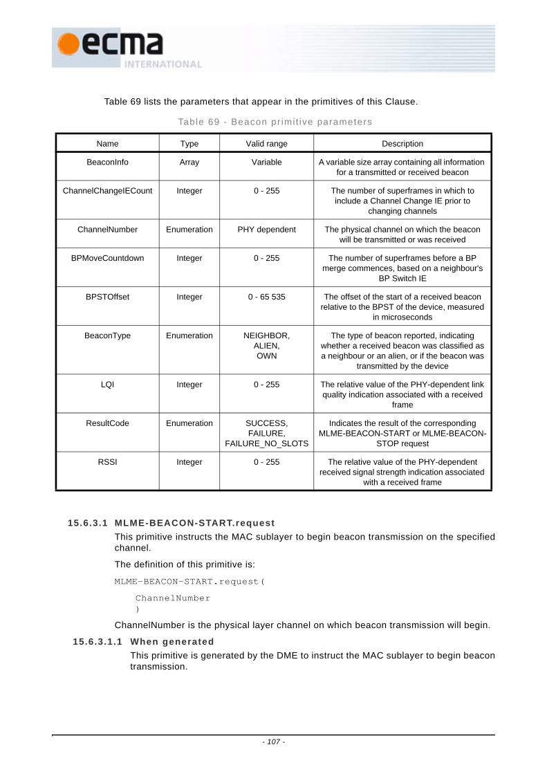
Table 69 lists the parameters that appear in the primitives of this Clause.
15.6.3.1 MLME-BEACON-START.requestThis primitive instructs the MAC sublayer to begin beacon transmission on the specifiedchannel.
The definition of this primitive is:
MLME-BEACON-START.request(
ChannelNumber)
ChannelNumber is the physical layer channel on which beacon transmission will begin.
15.6.3.1.1 When generatedThis primitive is generated by the DME to instruct the MAC sublayer to begin beacontransmission.
Table 69 - Beacon pr imit ive parameters
Name Type Valid range Description
BeaconInfo Array Variable A variable size array containing all information for a transmitted or received beacon
ChannelChangeIECount Integer 0 - 255 The number of superframes in which to include a Channel Change IE prior to
changing channels
ChannelNumber Enumeration PHY dependent The physical channel on which the beacon will be transmitted or was received
BPMoveCountdown Integer 0 - 255 The number of superframes before a BP merge commences, based on a neighbour's
BP Switch IE
BPSTOffset Integer 0 - 65 535 The offset of the start of a received beacon relative to the BPST of the device, measured
in microseconds
BeaconType Enumeration NEIGHBOR, ALIEN, OWN
The type of beacon reported, indicating whether a received beacon was classified as a neighbour or an alien, or if the beacon was
transmitted by the device
LQI Integer 0 - 255 The relative value of the PHY-dependent link quality indication associated with a received
frame
ResultCode Enumeration SUCCESS, FAILURE,
FAILURE_NO_SLOTS
Indicates the result of the corresponding MLME-BEACON-START or MLME-BEACON-
STOP request
RSSI Integer 0 - 255 The relative value of the PHY-dependent received signal strength indication associated
with a received frame
- 107 -

15.6.3.1.2 Effect of receiptWhen the MLME receives the request it initiates the process of starting to transmitbeacons on the indicated channel.
15.6.3.2 MLME-BEACON-START.confirmThis primitive confirms the completion of an MLME-BEACON-START request. Thisconfirmation indicates whether the first beacon has been transmitted.
The definition of this primitive is:
MLME-BEACON-START.confirm(
ResultCode)
ResultCode indicates whether beacons have begun to be successfully transmitted. If anoperation to start beacon transmission is not succeeding, it is a vendor specific decisionwhen to time out the operation and return FAILURE.
15.6.3.2.1 When generatedThis primitive is generated by the MLME as a result of an MLME-BEACON-START.request to indicate that the first beacon has been successfully transmitted orthat the operation has failed.
15.6.3.2.2 Effect of receiptThe recipient is notified of the results of the procedure of starting to transmitbeacons.
15.6.3.3 MLME-BEACON-STOP.requestThis primitive causes the MAC sublayer to stop transmitting beacons.
The definition of this primitive is:
MLME-BEACON-STOP.request(
)
15.6.3.3.1 When generatedThis primitive is generated by the DME to stop beacon transmission that was startedwith the MLME-BEACON-START request.
15.6.3.3.2 Effect of receiptThe MLME immediately initiates ending the transmission of beacons.
15.6.3.4 MLME-BEACON-STOP.confirmThis primitive confirms that beacon transmission has been stopped by the MLME afterthe DME issued the MLME-BEACON-STOP request.
The definition of this primitive is:
MLME-BEACON-STOP.confirm(
ResultCode)
ResultCode indicates whether the beacon operation successfully stopped. If endingbeacon transmission is not successful, it is a vendor specific decision when to time outthe operation and return FAILURE.
- 108 -
15.6.3.4.1 When generatedThis primitive is generated by the MLME as a result of an MLME-BEACON-STOP.request once beacon transmission has been successfully stopped or theoperation has failed.
15.6.3.4.2 Effect of receiptThe recipient is notified of the results of the procedure of stopping beacontransmission. A successful confirmation indicates at least one BP has passedwithout a beacon being transmitted.
15.6.3.5 MLME-BEACON-CHANGE-CHANNEL.requestThis primitive causes the MAC sublayer to change the channel on which it transmitsbeacons (and all other frames).
The definition of this primitive is:
MLME-BEACON-CHANGE-CHANNEL.request(
ChannelNumber,ChannelChangeIECount)
15.6.3.5.1 When generatedThis primitive is generated by the DME to select a new channel for transmission.
15.6.3.5.2 Effect of receiptThe MLME includes Channel Change IEs in zero or more superframes as specifiedby the DME. It changes the PHY channel it uses to the channel indicated by theChannelNumber parameter at the end of the superframe in which the ChannelChange Countdown field was zero, or at the end of the current superframe if theChannelChangeIECount parameter is zero.
15.6.3.6 MLME-BEACON-CHANGE-CHANNEL.confirmThis primitive confirms that the MLME has changed PHY channels as a result of aMLME-BEACON-CHANGE-CHANNEL request.
The definition of this primitive is:
MLME-BEACON-CHANGE-CHANNEL.confirm(
ResultCode)
ResultCode indicates whether the PHY channel was changed successfully. If changingthe PHY channel is not successful, it is a vendor specific decision when to time out theoperation and return FAILURE.
15.6.3.6.1 When generatedThis primitive is generated by the MLME as a result of an MLME-BEACON-CHANGE-CHANNEL.request once the PHY channel has been changed or theoperation has failed.
15.6.3.6.2 Effect of receiptThe recipient is notified of the results of the procedure of changing channels. Asuccessful confirmation indicates at least one BP has passed with beacontransmission and reception on the new channel.
- 109 -

15.6.3.7 MLME-BEACON.indicationThis indication informs the DME that a beacon was received or transmitted. Theindication occurs any time the device receives a beacon or transmits its own beacon.
The definition of this primitive is:
MLME-BEACON.indication(
BeaconInfo,ChannelNumber,BPSTOffset,BeaconType,LQI,RSSI)
BeaconInfo is an array including the MAC Header, beacon parameters, and allinformation elements for the received or transmitted beacon. Channel Number is thePHY channel on which the beacon was received or transmitted.
If the device is active, the MAC sublayer always indicates at least one beacon, its own,during its BP.
15.6.3.7.1 When generatedThis indication is generated by the MLME when it determines it has transmitted orreceived a beacon frame. Beacon indications for received beacons can occur anytime a device's receiver is enabled, whether scanning is enabled or not.
15.6.3.7.2 Effect of receiptThe recipient is notified that a beacon has been received and provided with allinformation contained in the beacon.
15.6.3.8 MLME-BEACON- MERGE-BP.requestThis primitive allows the DME to request initiation of the merging process of twopreviously separate BPs.
The definition of this primitive is:
MLME-BEACON-MERGE-BP.request(
BPSTOffset)
BPSTOffset identifies the BPST of the alien BP where the device will move.
15.6.3.8.1 When generatedThis primitive is generated by the DME to instruct the MAC sublayer to merge its BPwith an alien BP.
15.6.3.8.2 Effect of receiptWhen the MLME receives this primitive, the device relocates its BP to the alien BPaccording to 17.2.6.3.
15.6.3.9 MLME-BEACON-MERGE-BP.indicationThis indication informs the DME that a neighbour has announced it will change its BPSTas a result of a BP merge operation.
The definition of this primitive is:
MLME-BEACON-MERGE-BP.indication(
- 110 -

BPSTOffset,BPMoveCountdown)
15.6.3.9.1 When generatedThis indication is generated by the MLME when the device receives a BP Switch IEin a beacon from a neighbour.
15.6.3.9.2 Effect of receiptThe recipient is notified that a BP Switch IE was received and a BP merge mayresult.
15.6.3.10 MLME-BEACON-MERGE-BP.confirmThis primitive confirms that a BP merge has completed or terminated.
The definition of this primitive is:
MLME-BEACON-MERGE-BP.confirm(
ResultCode)
ResultCode indicates whether the merge operation successfully completed or wasterminated.
15.6.3.10.1 When generatedThis primitive is generated by the MLME as a result of an MLME-BEACON-MERGE-BP.request once the BP merge operation has completed or terminated.
15.6.3.10.2 Effect of receiptThe recipient is notified of the results of the BP merge procedure.
15.6.4 IE managementThe service primitives in this Clause provide access to and control of information containedin certain IEs, for use by higher layers. The primitives covered in this Clause are listed inTable 70.
Table 71 lists the parameters that appear in the primitives of this Clause.
15.6.4.1 MLME-SET-CAPABILITIES-IE.requestThis primitive changes the content of the Capabilities IE in the beacon.
Table 70 - IE Management pr imi t ives
Service Primitive Request Indication Response Confirm
MLME-SET-CAPABILITY-IE 15.6.4.1 15.6.4.2
MLME-IDENTIFICATION-IE 15.6.4.3 15.6.4.4
Table 71 - IE Management pr imit ive parameters
Name Type Valid range Description
CapIEData Array Variable A variable size array containing Capabilities IE data
IdentificationIEData Array Variable A variable size array containing the Identification IE data
ResultCode Enumeration SUCCESS, FAILURE
Indicates the result of the MLME-SET-CAPABILITIES-IE request
- 111 -

The definition of this primitive is:
MLME-SET-CAPABILITIES-IE.request(
CapIEData)
CapIEData is the data to use in the Capabilities IE in subsequent beacons.
15.6.4.1.1 When generatedThis primitive is generated by the DME to instruct the MAC sublayer to change theCapabilities IE content in the beacon.
15.6.4.1.2 Effect of receiptWhen the MLME receives the request it initiates changing the Capabilities IE contentin the beacon.
15.6.4.2 MLME-SET-CAPABILITIES-IE.confirmThis primitive confirms the result of an operation to change the Capabilities IE content inthe beacon in response to an MLME-SET-CAPABILITIES-IE request.
The definition of this primitive is:
MLME-SET-CAPABILITIES-IE.confirm(
ResultCode)
ResultCode indicates the result of the attempt to change the Capabilities IE content inthe beacon. If the Capabilities IE content can not be changed the primitive is generatedwith a FAILURE status.
15.6.4.2.1 When generatedThis primitive is generated by the MLME as a result of an MLME-SET-CAPABILITIES-IE.request with a successful return status to indicate that the firstbeacon has been transmitted with the changed Capabilities IE content. If MLME-SET-CAPABILITIES-IE.request was called when beacons were not beingtransmitted, a successful status indicates that the new Capabilities IE content will bein the beacon when the next beacon is sent.
15.6.4.2.2 Effect of receiptThe recipient is notified of the results of the procedure of changing the CapabilitiesIE content in the beacon.
15.6.4.3 MLME-IDENTIFICATION-IE.requestThis primitive controls the contents of the Identification IE in the beacon.
The definition of this primitive is:
MLME-IDENTIFICATION-IE.request(
IdentificationIEData)
15.6.4.3.1 When generatedThis primitive is generated by the DME to instruct the MAC sublayer to change thedevice's Identification IE content.
15.6.4.3.2 Effect of receiptWhen the MLME receives the request it changes the Identification IE content.
- 112 -

15.6.4.4 MLME-IDENTIFICATION-IE.confirmThis primitive confirms the result of an operation to change the Identification IE content.
The definition of this primitive is:
MLME-IDENTIFICATION-IE.confirm(
ResultCode)
ResultCode indicates the result of the attempt to change the Identification IE content. Ifthe Identification IE content cannot be changed the primitive is generated with aFAILURE status.
15.6.4.4.1 When generatedThis primitive is generated by the MLME as a result of an MLME-IDENTIFICATION-IE.request with a successful return status to indicate that the new content is storedand will be used in the next beacon to contain an Identification IE.
15.6.4.4.2 Effect of receiptThe recipient is notified of the results of the procedure of changing the IdentificationIE content.
15.6.5 PTK establishmentThe mechanism supports the procedure of establishing a new PTK with a peer MACsublayer. The primitives covered in this Clause are listed in Table 72.
Table 72 - PTK establ ishment pr imit ives
Service Primitive Request Indication Response Confirm
MLME-PTK 15.6.5.1 15.6.5.2 15.6.5.3 15.6.5.4
- 113 -

Table 73 lists the parameters that appear in the primitives of this Clause.
15.6.5.1 MLME-PTK.requestThis primitive requests establishment of a new PTK with a specified peer MAC sublayeras described in Clause 18.
The definition of this primitive is:
MLME-PTK.request(
DestEUI,MessageNumber,StatusCode,PTKID,MKID,PTKFailureTimeout)
15.6.5.1.1 When generatedThis primitive is generated by the DME for the local MAC sublayer to start a 4-wayhandshake procedure to establish a new PTK with a specified peer MAC sublayer.This primitive is also generated by the DME for the local MAC sublayer to continuewith an ongoing 4-way handshake procedure upon receiving a valid PTK commandcontaining a Message Number of 2 and a StatusCode of zero.
Table 73 - PTK establ ishment pr imit ive parameters
Name Type Valid range Description
SrcEUI EUI-48 Any valid unicast EUI-48 Specifies the EUI-48 of the device requesting to establish a new PTK by a 4-way handshake as described in Clause 18
DestEUI EUI-48 Any valid unicast EUI-48 Specifies the EUI-48 of the device requested to establish a new PTK by a 4-way handshake as described in Clause 18
MessageNumber Integer Any valid positive number as specified in Clause 18
Specifies the number of the message being conveyed in the 4-way handshake
StatusCode Integer Any valid value as specified in Clause 18
Specifies the status of the 4-way handshake
PTKID Integer A non-zero number as specified in Clause 18
Specifies the TKID of the new PTK established by the 4-way handshake
MKID Octet string 16 octets as specified in Clause 18
Identifies the master key used to establish a new PTK by a 4-way handshake
PTK Octet string 16 octets as specified in Clause 18
Specifies the new PTK established by the 4-way handshake
PTKFailureTimeout Integer ≥1 Specifies a time limit in microseconds after which the procedure of establishing a new
PTK must be terminated
ResultCode Enumeration RESPONSE_RECEIVED, INVALID_PARAMETERS,
TIMEOUT
Indicates the result of the corresponding MLME-PTK.request
- 114 -

15.6.5.1.2 Effect of receiptThe MAC sublayer initiates or continues with a 4-way handshake using the masterkey specified by the MKID parameter to establish a new PTK with a specified peerMAC sublayer specified by the DestEUI. If the MessageNumber in the MLME-PTK.request is 1, the MAC sublayer generates a new random number as the I-Nonceand transmits a PTK command containing the first message of the 4-way handshaketo the peer MAC sublayer. If the MessageNumber in the MLME-PTK.request is 3, theMAC sublayer uses its I-Nonce generated for the first message of the same 4-wayhandshake and transmits a PTK command containing the third message of the 4-wayhandshake to the peer MAC sublayer. The MLME subsequently issues an MLME-PTK.confirm to reflect the results.
15.6.5.2 MLME-PTK.indicationThis primitive reports the request or establishment of a new PTK with a specific peerMAC sublayer.
The definition of this primitive is:
MLME-PTK.indication(
SrcEUI,MessageNumber,StatusCode,PTKID,PTK,MKID)
15.6.5.2.1 When generatedThis primitive is generated by the MLME as a result of the request or establishmentof a new PTK with a specific peer MAC sublayer via a 4-way handshake procedure.Specifically, the primitive is generated by the MLME upon receiving a valid PTKcommand containing a Message Number of 1 or 3.
15.6.5.2.2 Effect of receiptThe DME is notified of the request or establishment of a new PTK. The DMEsubsequently issues an MLME-PTK.response to reflect the actions taken.
If the MessageNumber in the MLME-PTK.indication is 1, the DME verifies that theproposed PTKID is not being used by the local MAC sublayer for any temporal keyand that establishing a new PTK using the MKID with the requesting DME is anacceptable action. The DME includes the results of the verification in the StatusCodeparameter of MLME-PTK.response.
If the MessageNumber in the MLME-PTK.indication is 3 and the StatusCode in theMLME-PTK.response is zero, the DME follows to issue an MLME- KEY-UPDATE.request.
15.6.5.3 MLME-PTK.responseThis primitive responds to the request or establishment of a new PTK with a specificpeer MAC sublayer.
The definition of this primitive is:
MLME-PTK.response(
SrcEUI,MessageNumber,StatusCode,PTKID,
- 115 -

MKID)
15.6.5.3.1 When generatedThis primitive is generated by the DME as a result of an MLME-PTK.indicationreporting a valid request or establishment of a new PTK with a specific peer MACsublayer via a 4-way handshake procedure.
15.6.5.3.2 Effect of receiptIf the MessageNumber is 2, the MAC sublayer generates a new random number asthe R-Nonce and transmits a PTK command containing the second message of the4-way handshake to the specific peer MAC sublayer. If the MessageNumber is 4, theMAC sublayer uses its R-Nonce generated for the second message of the same 4-way handshake and transmits a PTK command containing the fourth message of the4-way handshake to the specific peer MAC sublayer. The PTK command carries theStatusCode parameter in its Status Code field.
15.6.5.4 MLME-PTK.confirmThis primitive reports the results of the attempt to establish a new PTK with a specifiedpeer MAC sublayer.
The definition of this primitive is:
MLME-PTK.confirm(
DestEUI,MessageNumber,StatusCode,PTKID,PTK,MKID,ResultCode)
15.6.5.4.1 When generatedThis primitive is generated by the MLME as a result of an MLME-PTK.request toestablish a new PTK with a specified peer MAC sublayer. Specifically, the primitive isgenerated by the MLME upon receiving a valid PTK command containing a MessageNumber of 2 or 4; or generated in case of INVALID_PARAMETERS orPTKFailureTimeout.
15.6.5.4.2 Effect of receiptThe DME is notified of the intermediate or final results of the procedure to establish anew PTK with a specified peer MAC sublayer.
If the MessageNumber is 4, the StatusCode is zero, and the ResultCode isRESPONSE_RECEIVED, the DME follows to issue an MLME-KEY-UPDATE.request.
15.6.6 GTK solicitat ion/distr ibutionThe mechanism supports the procedure of soliciting a new GTK from, or distributing a newGTK to, a peer MAC sublayer. The primitives covered in this Clause are listed in Table 74.
Table 74 - GTK sol ic i ta t ion/distr ibut ion pr imit ives
Service Primitive Request Indication Response Confirm
MLME-GTK 15.6.6.1 15.6.6.2 15.6.6.3 15.6.6.4
- 116 -

Table 75 lists the parameters that appear in the primitives of this Clause.
15.6.6.1 MLME-GTK.requestThis primitive requests that the MAC sublayer solicit a new GTK from, or distribute anew GTK to, a specified peer MAC sublayer as described in Clause 18.
The definition of this primitive is:
MLME-GTK.request(
DestEUI,TKID,MessageNumber,StatusCode,Global,GTK,
Table 75 - GTK request/d istr ibut ion pr imit ive parameters
Name Type Valid range Description
SrcEUI EUI-48 Any valid unicast EUI-48 Specifies the EUI-48 of the device soliciting or distributing a new GTK.
DestEUI EUI-48 Any valid unicast EUI-48 Specifies the EUI-48 of the device requested to distribute or receive a new
GTK.
TKID Integer A non-zero number as specified in Clause 18
Identifies the PTK used to distribute the new GTK.
MessageNumber Integer Any valid positive number as specified in Clause 18
Specifies the number of the message being conveyed in the GTK solicitation or
distribution process.
StatusCode Integer Any valid value as specified in Clause 18
Specifies the status of the GTK solicitation or distribution process.
GTK Octet string 16 octets as specified in Clause 18
Specifies the new GTK being distributed.
GTKID Integer A non-zero number as specified in Clause 18
Specifies the TKID of the new GTK being solicited or distributed.
GroupEUI EUI-48 Any valid multicast or broadcast EUI-48
Specifies the multicast group for which the GTK is being solicited or distributed, or
specifies the GTK is for broadcast.
Global Boolean FALSE, TRUE If TRUE, indicates that the GTK update applies to all broadcast and multicast traffic from the device that distributed this GTK. If FALSE, indicates the update applies only to
the specific GroupEUI identified.
GTKFailureTimeout Integer ≥1 Specifies a time limit in microseconds after which the procedure of soliciting or
distributing a new GTK must be terminated.
ResultCode Enumeration RESPONSE_RECEIVED, INVALID_PARAMETERS,
TIMEOUT
Indicates the result of the corresponding MLME-GTK.request.
- 117 -

GTKID,GroupEUI,GTKFailureTimeout)
15.6.6.1.1 When generatedThis primitive is generated by the DME for the local MAC sublayer to solicit a newGTK from, or distribute a new GTK to, a specified peer MAC sublayer.
15.6.6.1.2 Effect of receiptThe MAC sublayer initiates a new GTK solicitation or distribution procedure, basedon the value of MessageNumber. If MessageNumber is zero, the MAC sublayertransmits a GTK command soliciting a new GTK from the specified peer MACsublayer. If MessageNumber is one, the MAC sublayer distributes a new GTK to thespecified peer MAC sublayer. The MLME subsequently issues an MLME-GTK.confirm to reflect the results.
15.6.6.2 MLME-GTK.indicationThis primitive reports the solicitation or distribution of a new GTK by a specific peer MACsublayer.
The definition of this primitive is:
MLME-GTK.indication(
SrcEUI,TKID,MessageNumber,StatusCode,Global,GTK,GTKID,GroupEUI)
15.6.6.2.1 When generatedThis primitive is generated by the MLME as a result of receiving a valid solicitation ordistribution of a new GTK from a specific peer MAC sublayer.
15.6.6.2.2 Effect of receiptThe DME is notified of the solicitation or distribution of a new GTK. If the receivedMessageNumber is zero, and if the DME accepts the solicitation for a new GTK, itsubsequently issues an MLME-GTK.request to distribute a new GTK. If the receivedMessageNumber is one, the DME subsequently issues an MLME-GTK.response toreflect the actions taken with respect to the distribution of a new GTK.
If the StatusCode in the MLME-GTK.response is zero, the DME follows to issue anMLME-KEY-UPDATE.request.
15.6.6.3 MLME-GTK.responseThis primitive responds to the solicitation or distribution of a new GTK by a specific peerMAC sublayer.
The definition of this primitive is:
MLME-GTK.response(
SrcEUITKID,MessageNumber,
- 118 -

StatusCode,GTK,GTKID,GroupEUI)
15.6.6.3.1 When generatedThis primitive is generated by the DME as a result of an MLME-GTK.indicationreporting a distribution of a new GTK from a specific peer MAC sublayer.
15.6.6.3.2 Effect of receiptThe MAC sublayer transmits a GTK command responding to the distribution of a newGTK from the specific peer MAC sublayer. The GTK command carries theStatusCode parameter in its Status Code field.
15.6.6.4 MLME-GTK.confirmThis primitive reports the results of the attempt to solicit a new GTK from, or distribute anew GTK to, a specified peer MAC sublayer.
The definition of this primitive is:
MLME-GTK.confirm(
DestEUI,TKID,MessageNumber,StatusCode,GTK,GTKID,GroupEUI,ResultCode,)
15.6.6.4.1 When generatedThis primitive is generated by the MLME as a result of an MLME-GTK.request tosolicit a new GTK from, or distribute a new GTK to, a specified peer MAC sublayer.Specifically, the primitive is generated by the MLME upon successfully transmitting aGTK command soliciting a new GTK or upon successfully receiving a GTK commandresponding to the distribution of a new GTK; the primitive is also generated in caseof INVALID_PARAMETERS or GTKFailureTimeout.
15.6.6.4.2 Effect of receiptThe DME is notified of the results of the procedure to solicit a new GTK from, ordistribute a new GTK to, a specified peer MAC sublayer.
15.6.7 Temporal key updateThe mechanism supports the procedure of installing or deleting either a PTK or a GTK. Theprimitives covered in this Clause are listed in Table 76.
Table 76 - Temporal key update pr imit ives
Service Primitive Request Indication Response Confirm
MLME-KEY-UPDATE
15.6.7.1 15.6.7.2
- 119 -

Table 77 lists the parameters that appear in the primitives of this Clause.
15.6.7.1 MLME-KEY-UPDATE.requestThis primitive requests an update of a specified PTK or GTK.
The definition of this primitive is:
MLME-KEY-UPDATE.request(
PeerEUI,GroupEUI,KeyType,Global,TKID_Old,TKID,KEY)
15.6.7.1.1 When generatedThis primitive is generated by the DME for the local MAC sublayer to update a PTKor GTK.
15.6.7.1.2 Effect of receiptThe MLME removes the keying credential identified by TKID_Old that was previouslyinstalled if TKID_Old is not zero. The MLME then installs the new PTK or GTK along
Table 77 - Temporal Key update pr imit ive parameters
Name Type Valid range Description
PeerEUI EUI-48 Any valid unicast EUI-48 For a PTK, specifies the EUI-48 of the peer device sharing the PTK being updated. For a GTK,
specifies the EUI-48 of the device which distributed the GTK being updated.
GroupEUI EUI-48 Any valid multicast or broadcast EUI-48
Specifies the multicast or broadcast EUI-48 to which the new GTK applies.
KeyType Enumeration PTK, GTK Indicates whether the update is for a PTK or GTK.
Global Boolean FALSE, TRUE If TRUE, indicates that the GTK update applies to all broadcast and multicast traffic from the device that distributed this GTK. If FALSE, indicates the
update applies only to the specific GroupEUI identified.
TKID_Old Integer A non-zero number as specified in Clause 18, or 0
Specifies the TKID of the old PTK or GTK being replaced. If zero, indicates no old PTK or GTK is
being replaced.
TKID Integer A non-zero number as specified in Clause 18, or 0
Specifies the TKID of the new PTK or GTK being installed. If zero, indicates no new PTK or GTK is
being installed.
KEY Octet string 16 octets as specified in Clause 18
Specifies the new PTK or GTK being installed.
ResultCode Enumeration SUCCESS, INVALID_PARAMETERS
Indicates the result of the corresponding MLME-KEY-UPDATE.request.
- 120 -

with the TKID for the specified (PeerEUI, GroupEUI) if TKID is not zero. The MLMEsubsequently issues an MLME-KEY-UPDATE.confirm to reflect the results.
15.6.7.2 MLME-KEY-UPDATE.confirmThis primitive reports the results of the attempt to update a PTK or GTK.
The definition of this primitive is:
MLME-KEY-UPDATE.confirm(
PeerEUI,GroupEUI,TKID_Old,TKID,KEY,ResultCode)
15.6.7.2.1 When generatedThis primitive is generated by the MLME as a result of an MLME-KEY-UPDATE.request to update a PTK or GTK.
15.6.7.2.2 Effect of receiptThe DME is notified of the results of the procedure to update a specified PTK orGTK.
15.6.8 Security violation reportThe mechanism supports the procedure of reporting a security violation. The primitivescovered in this Clause are listed in Table 78.
Table 79 lists the parameters that appear in the primitives of this Clause.
15.6.8.1 MLME-SECURITY-VIOLATION.indicationThis primitive reports a security violation.
The definition of this primitive is:
MLME-SECURITY-VIOLATION.indication(
ViolationCode)
15.6.8.1.1 When generatedThis primitive is generated by the MLME as a result of encountering a securityviolation.
Table 78 - Secur i ty v io lat ion report pr imi t ives
Service Primitive Request Indication Response Confirm
MLME-SECURITY-VIOLATION 15.6.8.1
Table 79 - Secur i ty v io lat ion report pr imi t ive parameters
Name Type Valid range Description
ViolationCode Enumeration INVALID_MODE, INVALID_MIC, INVALID_TKID,
REPLAYED_FRAME
Indicates the cause of a security violation.
- 121 -

15.6.8.1.2 Effect of receiptThe DME is notified of the cause of the security violation.
15.6.9 Pseudo-random function (PRF)This mechanism provides higher layers through the DME with access to the MAC PRF. Forsimplicity, this primitive only provides 256-bit random numbers. Smaller quantities may beextracted from the result without compromising the randomness of the result. Theprimitives covered in this Clause are listed in Table 80.
Table 81 lists the parameters that appear in the primitives of this Clause.
15.6.9.1 MLME-PRF.requestThis primitive requests generation of a 256-bit pseudo-random number using the MACPRF.
The definition of this primitive is:
MLME-PRF.request(
Key,Nonce,DataBlocks,DataLength)
15.6.9.1.1 When generatedThis primitive is generated by the DME to request that the MAC sublayer generate arandom number using the MAC PRF facility.
Table 80 - PRF pr imit ives
Service Primitive Request Indication Response Confirm
MLME-PRF 15.6.9.1 15.6.9.2
Table 81 - PRF pr imit ive parameters
Name Type Valid range Description
Key Octet string A 16-octet symmetric key as specified in Clause 18
The key to be used for generating a random number
Nonce Octet string 13 octets as specified in Clause 18
The nonce to be used for generating a random number
DataBlocks Octet string 0 - 65 535 octets Arbitrary data to be used as input to the MAC PRF
DataLength Integer 0 - 65 535 Length in octets of DataBlocks
RandomNumber Octet string 32 octets The generated 256-bit random number
ResultCode Enumeration SUCCESS, INVALID_PARAMETERS
The result of the MLME-PRF.request
- 122 -

15.6.9.1.2 Effect of receiptThe local MAC sublayer calls the PRF defined in Clause 18 with the parameterscontained in the primitive to generate a 256-bit random number. The semantics ofthe call to the PRF are:
PRF-256(Key, Nonce, "MLME_PRFrequest", DataBlocks, DataLength)
15.6.9.2 MLME-PRF.confirmThis primitive returns the result of the previously initiated MLME-PRF.request.
The definition of this primitive is:
MLME-PRF.confirm(
RandomNumber,ResultCode)
15.6.9.2.1 When generatedThis primitive is generated by the MLME as a result of an MLME-PRF.request togenerate a 256-bit random number using the MAC PRF.
15.6.9.2.2 Effect of receiptThe DME is notified of the results of the procedure of generating a 256-bit randomnumber using the MAC PRF facility.
15.6.10 Application-specif ic IE (ASIE) managementThe service primitives in this Clause allow the DME to add or remove an ASIE from thebeacon content. The primitives covered in this Clause are listed in Table 82.
Table 83 lists the parameters that appear in the primitives of this Clause.
15.6.10.1 MLME-ASIE-ADD.requestThis primitive changes the beacon content by adding an ASIE.
Table 82- ASIE management pr imit ives
Service Primitive Request Indication Response Confirm
MLME-ASIE-ADD 15.6.10.1 15.6.10.2
MLME-ASIE-REMOVE 15.6.10.3 15.6.10.4
MLME-ASIE 15.6.10.5
Table 83 - ASIE management pr imi t ive parameters
Name Type Valid range Description
ASIEData Array Variable A variable size array containing ASIE data
ASIEHandle Integer 0 - 255 A handle associated with an ASIE that has been added to the beacon content
PositionAdvice Integer 0 - 255 The recommended position of the ASIE in the beacon
ResultCode Enumeration SUCCESS, FAILURE
Indicates the result of the MLME-ASIE-ADD or MLME-ASIE-REMOVE requests
- 123 -
The definition of this primitive is:
MLME-ASIE-ADD.request(
ASIEHandle,ASIEData,PositionAdvice)
ASIEData is the data to be added to the beacon as an ASIE. PositionAdvice indicatesthe position where the new ASIE is added to the beacon. The ASIE is added after anyIEs with Element ID less than or equal to PositionAdvice, and before any IEs withElement ID greater than PositionAdvice.
15.6.10.1.1 When generatedThis primitive is generated by the DME to instruct the MAC sublayer to add an ASIEto the beacon contents.
15.6.10.1.2 Effect of receiptWhen the MLME receives the request it initiates adding the ASIE to the beaconcontents.
15.6.10.2 MLME-ASIE-ADD.confirmThis primitive confirms the result of an operation to add an ASIE to the beacon inresponse to an MLME-ASIE-ADD request.
The definition of this primitive is:
MLME-ASIE-ADD.confirm(
ASIEHandle,ResultCode)
ResultCode indicates the result of the attempt to add an ASIE to the beacon. If anoperation to add an ASIE to the beacon is not succeeding, it is a vendor specificdecision when to time out the operation and return FAILURE. If the ASIE has beensuccessfully added to the beacon contents, ASIEHandle is returned with a handle to theASIE. This handle can be used with the MLME-ASIE-REMOVE request to remove theASIE from the beacon content.
15.6.10.2.1 When generatedThis primitive is generated by the MLME as a result of an MLME-ASIE-ADD.requestwith a successful return status to indicate that the first beacon has been successfullytransmitted with the ASIE. If MLME-ASIE-ADD.request was called when beaconswere not being transmitted, a successful status indicates that the ASIE will be in thebeacon when the next beacon is sent. If the ASIE cannot be added to the beaconcontent the primitive is generated with a FAILURE status.
15.6.10.2.2 Effect of receiptThe recipient is notified of the results of the procedure of adding an ASIE to thebeacon content.
15.6.10.3 MLME-ASIE-REMOVE.requestThis primitive instructs the MAC sublayer to remove an ASIE from the beacon content.
The definition of this primitive is:
- 124 -

MLME-ASIE-REMOVE.request(
ASIEHandle)
ASIEHandle is the handle of an ASIE that was successfully added to the beacon.
15.6.10.3.1 When generatedThis primitive is generated by the DME to remove an ASIE from the beacon.
15.6.10.3.2 Effect of receiptThe MAC sublayer immediately initiates removing the ASIE indicated by ASIEHandlefrom the beacon content.
15.6.10.4 MLME-ASIE-REMOVE.confirmThis primitive confirms that the attempt to remove an ASIE from the beacon in responseto an MLME-ASIE-REMOVE request has completed.
The definition of this primitive is:
MLME-ASIE-REMOVE.confirm(
ASIEHandle,ResultCode)
ResultCode indicates the status of the operation to remove an ASIE from the beaconcontent.
15.6.10.4.1 When generatedThis primitive is generated by the MLME as a result of an MLME-ASIE-REMOVE.request. If beacons are being transmitted a beacon must have been sentwithout the ASIE for a successful confirmation. If beacons are not being transmitteda successful confirmation indicates that the next beacon sent will not include theASIE.
15.6.10.4.2 Effect of receiptThe recipient is notified of the results of the procedure of removing an ASIE from thebeacon.
15.6.10.5 MLME-ASIE.indicationThis primitive indicates the reception of an ASIE from a neighbour.
The definition of this primitive is:
MLME-ASIE.indication(
ASIEData)
15.6.10.5.1 When generatedThis primitive is generated by the MLME when a beacon is received that contains anASIE.
15.6.10.5.2 Effect of receiptThe recipient is notified of reception of an ASIE.
- 125 -
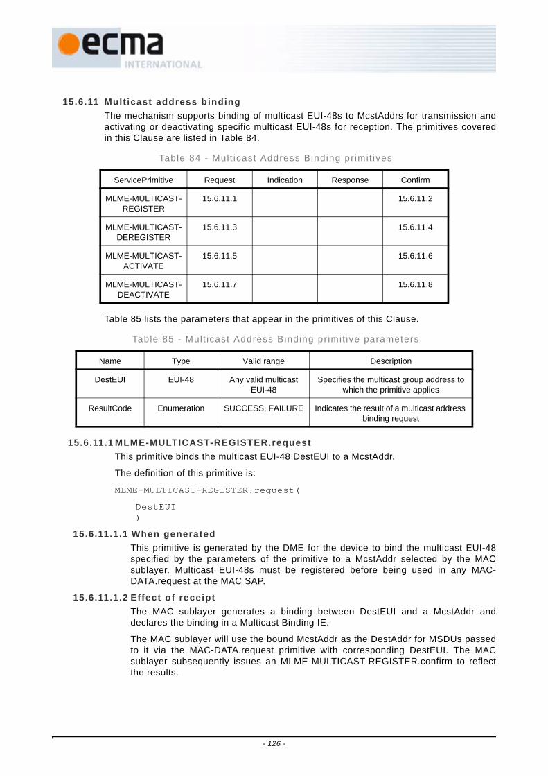
15.6.11 Mult icast address bindingThe mechanism supports binding of multicast EUI-48s to McstAddrs for transmission andactivating or deactivating specific multicast EUI-48s for reception. The primitives coveredin this Clause are listed in Table 84.
Table 85 lists the parameters that appear in the primitives of this Clause.
15.6.11.1 MLME-MULTICAST-REGISTER.requestThis primitive binds the multicast EUI-48 DestEUI to a McstAddr.
The definition of this primitive is:
MLME-MULTICAST-REGISTER.request(
DestEUI)
15.6.11.1.1 When generatedThis primitive is generated by the DME for the device to bind the multicast EUI-48specified by the parameters of the primitive to a McstAddr selected by the MACsublayer. Multicast EUI-48s must be registered before being used in any MAC-DATA.request at the MAC SAP.
15.6.11.1.2 Effect of receiptThe MAC sublayer generates a binding between DestEUI and a McstAddr anddeclares the binding in a Multicast Binding IE.
The MAC sublayer will use the bound McstAddr as the DestAddr for MSDUs passedto it via the MAC-DATA.request primitive with corresponding DestEUI. The MACsublayer subsequently issues an MLME-MULTICAST-REGISTER.confirm to reflectthe results.
Table 84 - Mul t icast Address Binding pr imit ives
ServicePrimitive Request Indication Response Confirm
MLME-MULTICAST-REGISTER
15.6.11.1 15.6.11.2
MLME-MULTICAST-DEREGISTER
15.6.11.3 15.6.11.4
MLME-MULTICAST-ACTIVATE
15.6.11.5 15.6.11.6
MLME-MULTICAST-DEACTIVATE
15.6.11.7 15.6.11.8
Table 85 - Mult icast Address Binding pr imit ive parameters
Name Type Valid range Description
DestEUI EUI-48 Any valid multicast EUI-48
Specifies the multicast group address to which the primitive applies
ResultCode Enumeration SUCCESS, FAILURE Indicates the result of a multicast address binding request
- 126 -
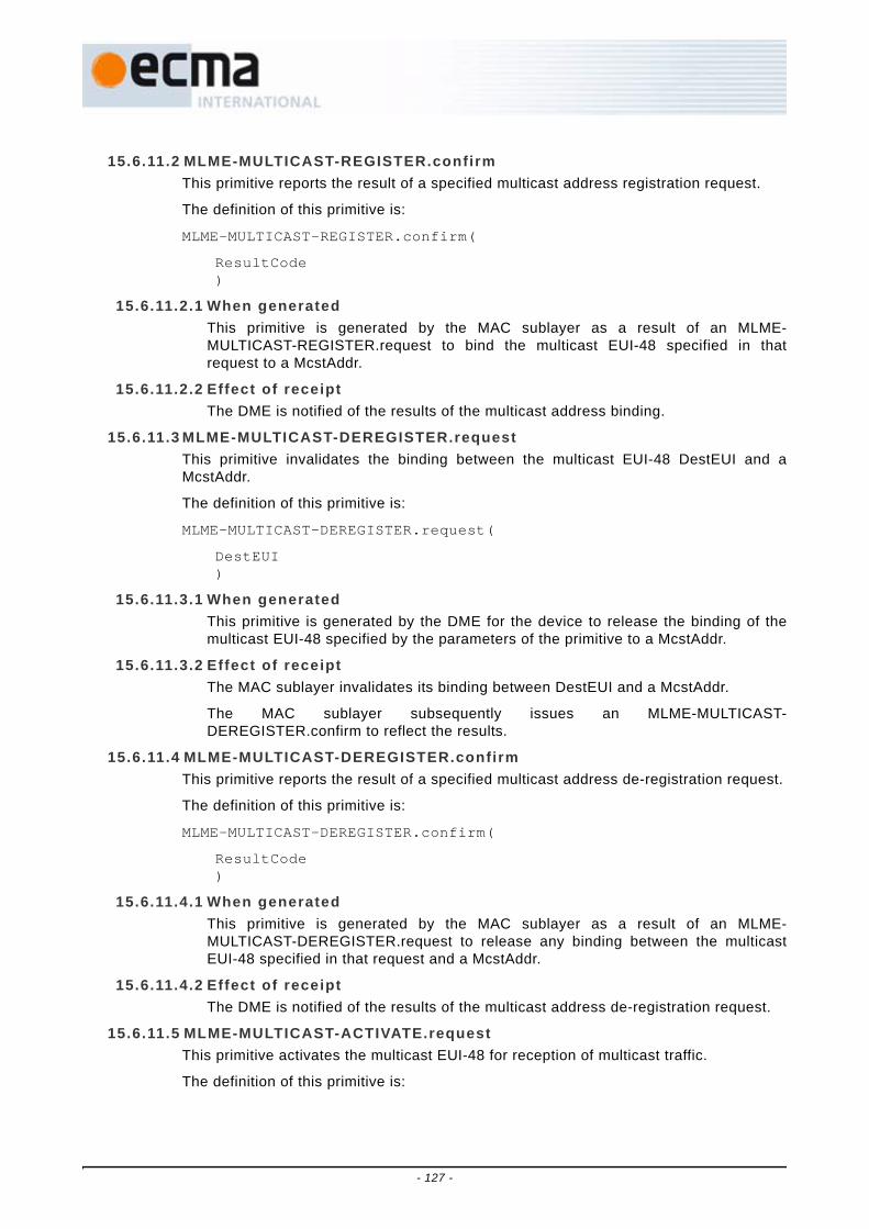
15.6.11.2 MLME-MULTICAST-REGISTER.confirmThis primitive reports the result of a specified multicast address registration request.
The definition of this primitive is:
MLME-MULTICAST-REGISTER.confirm(
ResultCode)
15.6.11.2.1 When generatedThis primitive is generated by the MAC sublayer as a result of an MLME-MULTICAST-REGISTER.request to bind the multicast EUI-48 specified in thatrequest to a McstAddr.
15.6.11.2.2 Effect of receiptThe DME is notified of the results of the multicast address binding.
15.6.11.3 MLME-MULTICAST-DEREGISTER.requestThis primitive invalidates the binding between the multicast EUI-48 DestEUI and aMcstAddr.
The definition of this primitive is:
MLME-MULTICAST-DEREGISTER.request(
DestEUI)
15.6.11.3.1 When generatedThis primitive is generated by the DME for the device to release the binding of themulticast EUI-48 specified by the parameters of the primitive to a McstAddr.
15.6.11.3.2 Effect of receiptThe MAC sublayer invalidates its binding between DestEUI and a McstAddr.
The MAC sublayer subsequently issues an MLME-MULTICAST-DEREGISTER.confirm to reflect the results.
15.6.11.4 MLME-MULTICAST-DEREGISTER.confirmThis primitive reports the result of a specified multicast address de-registration request.
The definition of this primitive is:
MLME-MULTICAST-DEREGISTER.confirm(
ResultCode)
15.6.11.4.1 When generatedThis primitive is generated by the MAC sublayer as a result of an MLME-MULTICAST-DEREGISTER.request to release any binding between the multicastEUI-48 specified in that request and a McstAddr.
15.6.11.4.2 Effect of receiptThe DME is notified of the results of the multicast address de-registration request.
15.6.11.5 MLME-MULTICAST-ACTIVATE.requestThis primitive activates the multicast EUI-48 for reception of multicast traffic.
The definition of this primitive is:
- 127 -

MLME-MULTICAST-ACTIVATE.request(
DestEUI)
15.6.11.5.1 When generatedThis primitive is generated by the DME for the device to activate reception of trafficon the multicast EUI-48 specified by the parameters of the primitive. A multicastaddress must be activated before the MAC sublayer will deliver any MSDUs with themulticast DestEUI to the MAC client via the MAC-DATA.indication at the MAC SAP.
15.6.11.5.2 Effect of receiptThe MAC sublayer modifies its receive multicast filters to receive traffic addressed toa McstAddr that the source of the traffic has announced is bound to the multicastEUI-48 specified by the primitive.
The MAC sublayer subsequently issues an MLME-MULTICAST-ACTIVATE.confirmto reflect the results.
15.6.11.6 MLME-MULTICAST-ACTIVATE.confirmThis primitive reports the result of a multicast traffic activation request.
The definition of this primitive is:
MLME-MULTICAST-ACTIVATE.confirm(
ResultCode)
15.6.11.6.1 When generatedThis primitive is generated by the MAC sublayer as a result of an MLME-MULTICAST-ACTIVATE.request to activate the multicast EUI-48 specified in thatrequest.
15.6.11.6.2 Effect of receiptThe DME is notified of the results of the procedure of activating the specifiedmulticast EUI-48.
15.6.11.7 MLME-MULTICAST-DEACTIVATE.requestThis primitive deactivates the multicast EUI-48 for reception of multicast traffic. If themulticast EUI-48 is the NULL address (FF FF FF FF FF FF) all multicast EUI-48s aredeactivated.
The definition of this primitive is:
MLME-MULTICAST-DEACTIVATE.request(
DestEUI)
15.6.11.7.1 When generatedThis primitive is generated by the DME for the device to deactivate reception oftraffic on the multicast EUI-48 specified by the parameters of the primitive.
15.6.11.7.2 Effect of receiptThe MAC sublayer modifies its multicast receive filters to discard MSDUs receivedwith DestAddr set to a McstAddr that the source of the MSDU has announced isbound to the multicast EUI-48 specified by the primitive.
- 128 -

The MAC sublayer subsequently issues an MLME-MULTICAST-DEACTIVATE.confirm to reflect the results.
15.6.11.8 MLME-MULTICAST-DEACTIVATE.confirmThis primitive reports the result of a multicast traffic deactivation request.
The definition of this primitive is:
MLME-MULTICAST-DEACTIVATE.confirm(
ResultCode)
15.6.11.8.1 When generatedThis primitive is generated by the MAC sublayer as a result of an MLME-MULTICAST-DEACTIVATE.request to deactivate the multicast traffic specified in thatrequest.
15.6.11.8.2 Effect of receiptThe DME is notified of the results of the procedure of deactivating the specifiedmulticast traffic.
15.6.12 Link eventsThe service primitives in this Clause are provided for the DME to monitor events related tothe link status. The primitives covered in this Clause are listed in Table 86.
Table 86 - L ink event pr imi t ives
Service Primitive Request Indication Response Confirm
MLME-LINK-EVENT 15.6.12.1 15.6.12.2 15.6.12.3
- 129 -

Table 87 lists the parameters that appear in the primitives of this Clause.
15.6.12.1 MLME-LINK-EVENT.requestThis primitive enables or disables the observation of link events for a specified link.
The definition of this primitive is:
MLME-LINK-EVENT.request(RemoteEUI,MonitorState)
Table 87 - L ink event pr imi t ive parameters
Name Type Valid range Description
AccessMethod Enumeration PCA, DRP The access method used for transmission or receipt of a frame
Beacon Enumeration FALSE, TRUE Indicates whether a received frame was a beacon
BPSTOffset Integer 0 - 65 535 The offset of the start of a received frame relative to the BPST of the device, measured
in microseconds
RemoteEUI EUI-48 Any valid unicast EUI-48 Specifies the EUI-48 of the remote device in the link
LinkEveneType Enumeration RECEIVE_SUCCESS, RECEIVE_ERROR,
TRANSMIT_SUCCESS, TRANSMIT_ERROR
The type of link event that occurred on a link being monitored
MonitorState Enumeration DISABLED, ENABLED
Specifies whether link event observation is active for the specified link
PayloadSize Integer 0 to pMaxPayloadSize Size of a transmitted or received frame payload
PHYRate Enumeration RATE_53_3, RATE_80,
RATE_106_7, RATE_160, RATE_200, RATE_320, RATE_400, RATE_480
PHY data rate at which a frame was transmitted or received
ResultCode Enumeration SUCCESS, FAILURE
Appears in MLME-LINK-EVENT.confirm and indicates the result of the corresponding
MLME-LINK-EVENT request
RetryCount Integer Variable Retry count for this transmission
ReceiveErrorInfo Enumeration PAYLOAD_ERROR,UNSUPPORTED_RATE_ERROR,
GENERAL_ERROR
Provides additional information for an RECEIVE_ERROR
DeliveriID integer As defined in 16.2.1.5 The Delivery ID associated with a transmitted or received frame
- 130 -

RemoteEUI is the EUI-48 for the remote device for which the link monitoring state is tobe changed. MonitorState indicates whether monitoring link events is to be enabled ordisabled for the specified link. Links are not monitored by default.
15.6.12.1.1 When generatedThis primitive is generated by the DME to enable or disable link monitoring for thespecified link.
15.6.12.1.2 Effect of receiptThe MLME initiates enabling or disabling observation of link events for the specifiedlink.
15.6.12.2 MLME-LINK-EVENT.indicationThis indication informs the DME that an event occurred for a link with monitoringenabled.
The definition of this primitive is:
MLME-LINK-EVENT.indication(
AccessMethod,Beacon,BPSTOffset,LinkEventType,PayloadSize,PHYRate,RemoteEUI,RetryCount,ReceiveErrorInfo,DeliveryID)
AccessMethod indicates if the frame associated with this event occurred during a DRPreservation or during PCA access time. Beacon indicates whether the event isassociated with the receipt of a beacon. AccessMethod is undefined if Beacon is TRUE.RemoteEUI is the EUI-48 of the remote device associated with the link event.LinkEventType indicates the type of event that has occurred for the link that is being
- 131 -

monitored. The possible link event types and their meaning for frames that are receivedin different ways are summarized and described in Table 88.
PayloadSize is the size of the frame associated with the link event (not including theFCS). PHYRate is the rate at which the frame associated with the link event wastransmitted or received. ReceiveErrorInfo provides additional information if the eventype is an RECEIVE_ERROR - it is undefined for other event types. RetryCount isnumber of times the transmission was attempted. DeliveryID is the Delivery IDassociated with the frame that produced the link event if the event occurred during areservation.
15.6.12.2.1 When generatedThis indication is generated by the MLME when it determines a link event hasoccurred for a link that is being monitored.
15.6.12.2.2 Effect of receiptThe recipient is notified that an event has occurred for a link that is being monitored.
15.6.12.3 MLME-LINK-EVENT.confirmThis confirmation indicates that a request to enable or disable link monitoring initiated bythe MLME-LINK-EVENT request has been completed.
The definition of this primitive is:
MLME-LINK-EVENT.confirm(
ResultCode)
ResultCode indicates whether the operation to change whether a link is monitored hassuccessfully completed. If changing the state is not succeeding, it is a vendor specificdecision when to time out the operation and return FAILURE.
15.6.12.3.1 When generatedThis primitive is generated by the MLME as a result of an MLME-LINK-EVENT.request once the requested state has been entered or the operation hasfailed.
Table 88 - L ink event types
Beacon DRP/PCA No-ACK DRP/PCA IMM-ACK, B-ACK
RECEIVE_SUCCESS Beacon from RemoteEUI received correctly
Frame received correctly from RemoteEUI
Frame received correctly from RemoteEUI
RECEIVE_ERROR Beacon from RemoteEUI received with
RECEIVE_ERROR
Frame received from RemoteEUI with
RECEIVE_ERROR
Frame received from RemoteEUI with
RECEIVE_ERROR
TRANSMIT_SUCCESS N/A Frame transmitted to RemoteEUI
Frame transmitted to RemoteEUI and
acknowledgement received
TRANSMIT_ERROR N/A N/A Frame transmitted to RemoteEUI and no acknowledgement
received
- 132 -
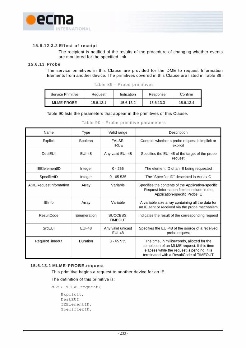
15.6.12.3.2 Effect of receiptThe recipient is notified of the results of the procedure of changing whether eventsare monitored for the specified link.
15.6.13 ProbeThe service primitives in this Clause are provided for the DME to request InformationElements from another device. The primitives covered in this Clause are listed in Table 89.
Table 90 lists the parameters that appear in the primitives of this Clause.
15.6.13.1 MLME-PROBE.requestThis primitive begins a request to another device for an IE.
The definition of this primitive is:
MLME-PROBE.request(
Explicit,DestEUI,IEElementID,SpecifierID,
Table 89 - Probe pr imit ives
Service Primitive Request Indication Response Confirm
MLME-PROBE 15.6.13.1 15.6.13.2 15.6.13.3 15.6.13.4
Table 90 - Probe pr imit ive parameters
Name Type Valid range Description
Explicit Boolean FALSE, TRUE
Controls whether a probe request is implicit or explicit
DestEUI EUI-48 Any valid EUI-48 Specifies the EUI-48 of the target of the probe request
IEEIelementID Integer 0 - 255 The element ID of an IE being requested
SpecifierID Integer 0 - 65 535 The “Specifier ID” described in Annex C
ASIERequestInformation Array Variable Specifies the contents of the Application-specific Request Information field to include in the
Application-specific Probe IE
IEInfo Array Variable A variable size array containing all the data for an IE sent or received via the probe mechanism
ResultCode Enumeration SUCCESS, TIMEOUT
Indicates the result of the corresponding request
SrcEUI EUI-48 Any valid unicast EUI-48
Specifies the EUI-48 of the source of a received probe request
RequestTimeout Duration 0 - 65 535 The time, in milliseconds, allotted for the completion of an MLME request. If this time elapses while the request is pending, it is
terminated with a ResultCode of TIMEOUT
- 133 -

RequestTimeout)
Explicit indicates whether the probe request is to be performed through beacons orusing command frames. Explicit probe requests are performed using command frames,while implicit probe requests are made through beacons. DestEUI is the device ID of thetarget device for the probe request. The IEElementID is the element ID for theInformation Element that is being requested through the probe request. If IEElementIDspecifies an ASIE, then SpecifierID and ASIERequestInformation must be provided.SpecifierID identifies the organizational definer of the ASIE, andASIERequestInformation specifies the organization-specific information to include in therequest. RequestTimeout is the maximum time a device should wait to complete theprobe request, and should account for request and response delays up tomMaxLostBeacons superframes if the request is implicit.
The definition of the request primitive to request a single IE does not prohibit animplementation from requesting multiple IEs in a single request.
15.6.13.1.1 When generatedThis primitive is generated by the DME to initiate a probe request. A probe request isonly sent to a device that indicates it supports probe requests in its Capabilities IE.
15.6.13.1.2 Effect of receiptThe MLME initiates the probe request through the specified mechanism. If implicit,the request must be attempted in the next beacon transmitted. If the mechanism isexplicit, the MAC sublayer issues the probe request using command frames, usingan immediate acknowledgement policy.
15.6.13.2 MLME-PROBE.indicationThis indication informs the DME that a probe request was received from another device.
The definition of this primitive is:
MLME-PROBE.indication(
IEElementID,SpecifierIDExplicitSrcEUI)
SrcEUI is the device ID of the device that sent the probe request. The IEElementID isthe element ID for the Information Element that is being requested through the proberequest.
15.6.13.2.1 When generatedThis indication is generated by the MLME when it receives a probe request.
15.6.13.2.2 Effect of receiptThe recipient is notified that a probe request was received.
15.6.13.3 MLME-PROBE.responseIn response to a probe request, this primitive causes the requested Information Elementto be transmitted to the requestor.
The definition of this primitive is:
MLME-PROBE.response(
Explicit,DestEUI,
- 134 -

IEInfo,TransmissionTimeout)
Explicit indicates whether the probe request is to be performed through beacons orusing command frames. The use of Explicit must be set to the same value as what wasdelivered in the corresponding probe request. DestEUI is the device ID of the targetdevice for the probe request. The IEInfo array contains the full IE to be transmitted.Transmission timeout is the timeout for the probe response if explicit access is used.Transmission timeout is not used if the request is implicit.
15.6.13.3.1 When generatedThis primitive is generated by the DME in response to receipt of a Probe Request IE,whether received in the beacon or signalled by MLME-PROBE.indication.
15.6.13.3.2 Effect of receiptThe MLME initiates the probe response through the specified mechanism. Ifmechanism is through the beacon, the response is attempted in the next beacontransmitted. If the mechanism is explicit, the MLME issues the probe response usingan immediate acknowledgement policy.
15.6.13.4 MLME-PROBE.confirmThis indication informs the DME that a probe response was received from anotherdevice.
The definition of this primitive is:
MLME-PROBE.confirm(
IEInfo,SrcEUI,ResultCode)
SrcEUI is the device ID of the device that sent the probe response. The IEInfo is theinformation element data provided in the probe response. ResultCode indicatesSUCCESS if the confirmation is received within the RequestTimeout period, orTIMEOUT if RequestTimeout expired before receiving the confirmation.
15.6.13.4.1 When generatedThis indication is generated by the MLME when it receives a probe response throughPCA traffic. A probe response through a beacon is received by the DME through aMLME-BEACON.indication.
15.6.13.4.2 Effect of receiptThe recipient is notified that a probe response was received.
- 135 -

15.6.14 Hibernation and sleep cycleThe service primitives in this Clause are provided for the DME to control hibernation,hibernation anchor support, and sleep cycles during a superframe. The primitives coveredin this Clause are listed in Table 91.
Table 91 - Hibernat ion pr imit ives
Service Primitive Request Indication Response Confirm
MLME-HIBERNATE 15.6.14.1 15.6.14.2
MLME-WAKE 15.6.14.3 15.6.14.4 15.6.14.5
MLME-HIBERNATION-ANCHOR 15.6.14.6 15.6.14.7 15.6.14.8
MLME-SLEEP-SCHEDULE 15.6.14.9 15.6.14.10
- 136 -

Table 92 lists the parameters that appear in the primitives of this Clause.
Table 92 - Hibernat ion pr imit ive parameters
Name Type Valid range Description
Start Integer 0 - N The number of superframes before the device will enter hibernation mode. N is
implementation-specific
InitialCountdown Integer 1 - 255 The number of superframes a device will indicate its intent to hibernate before
hibernation begins
HibernationDuration Integer 1 - 255 The number of superframes the device intends to hibernate
Repetitive Boolean FALSE, TRUE TRUE if the device will enter hibernate mode periodically based on the
HibernationDuration and WakeDuration parameters
WakeDuration Integer 1 - N The number of superframes that a device will be in active mode after
leaving hibernation mode, if Repetitive is used. N is implementation-specific
AnchorOperation Enumeration ACTIVATE, DEACTIVATE
Specifies whether device will start or stop operating as a hibernation anchor
OnInNeighborHardReservations Boolean FALSE, TRUE Indicates if a device in ON_PER_LOAD sleep mode should be on during neighbours' hard reservations
OnInNeighborSoftReservations Boolean FALSE, TRUE Indicates if a device in ON_PER_LOAD sleep mode should be on during
neighbours' soft reservations
OnForPCA Boolean FALSE, TRUE Indicates if a device in ON_PER_LOAD sleep mode should be on during MASs
available for PCA
PCAMASCount Integer 0 - 255 Indicates the maximum number of MASs per superframe that the device
should be on for PCA
ResultCode Enumeration SUCCESS, FAILURE,
FAILURE_NO_SLOTS
Indicates the result of the corresponding MLME-HIBERNATE or MLME-WAKE
request
SleepMode Enumeration ALWAYS_ON, ON_PER_SCHEDULE,
ON_PER_LOAD
Indicates the type of sleep operation a device should perform
SleepSchedule Bitmap one bit per MAS Each bit indicates if the device should sleep or receive traffic during the
corresponding MAS
- 137 -

15.6.14.1 MLME-HIBERNATE.requestThis primitive instructs the MAC sublayer to begin the hibernation process. Duringhibernation the MAC sublayer ceases all operations on the medium includingtransmission of beacons.
The definition of this primitive is:
MLME-HIBERNATE.request(
Start,InitialCountdown,HibernationDurationRepetitive,WakeDuration)
Before hibernation begins the MAC sublayer adds the Hibernation Mode IE to itsbeacon. InitialCountdown indicates how many superframes the Hibernation Mode IE willbe included in the beacon before hibernation begins. HibernationDuration indicates thenumber of superframes the hibernation is intended to last. HibernationDuration is usedin the Hibernation Mode IE which includes the number of superframes the deviceintends to hibernate.
15.6.14.1.1 When generatedThis primitive is generated by the DME to instruct the MAC sublayer to begin thehibernation process. This request may be made at any time after the MLME-WAKE.indication is received if another hibernation request was previously active.
15.6.14.1.2 Effect of receiptWhen the MLME receives the request it initiates the hibernation process.
15.6.14.2 MLME-HIBERNATE.confirmThis primitive confirms the result of the hibernation operation started by the MLME-HIBERNATE.request.
The definition of this primitive is:
MLME-HIBERNATE.confirm(
ResultCode)
ResultCode indicates the result of the attempt to begin the hibernation process. If anoperation to start the hibernation process is not succeeding, it is a vendor specificdecision when to time out the operation and return FAILURE. A return code ofSUCCESS indicates that a beacon has been sent containing the Hibernation Mode IE.
15.6.14.2.1 When generatedThis primitive is generated by the MLME as a result of an MLME-HIBERNATE.request to indicate that the first beacon has been transmitted with theHibernation Mode IE or that the operation has failed.
15.6.14.2.2 Effect of receiptThe recipient is notified of the results of the procedure of starting the hibernationprocess.
15.6.14.3 MLME-WAKE.requestThis primitive instructs the MAC sublayer to immediately exit hibernation mode andresume transmission of beacons as soon as possible, regardless of a previously-scheduled hibernation period length. This primitive also cancels any previous
- 138 -

hibernation mode request and instructs the MAC sublayer to remain in active mode untilfurther notice.
The definition of this primitive is:
MLME-WAKE.request(
)
15.6.14.3.1 When generatedThis primitive is generated by the DME to end the hibernation process and resumetransmission of beacons.
15.6.14.3.2 Effect of receiptThe MAC sublayer immediately ends hibernation and resumes transmission ofbeacons. If this primitive is used before the MAC sublayer has begun hibernation(while it is still transmitting beacons with the Hibernation Mode IE) the MAC sublayerattempts to remove the Hibernation Mode IE from the beacon and does not continuethe hibernation process.
15.6.14.4 MLME-WAKE.indicationThis indication informs the DME that the MAC sublayer has begun the process of exitinghibernation.
The definition of this primitive is:
MLME-WAKE.indication(
)
15.6.14.4.1 When generatedThis indication is generated by the MLME when it begins to scan the channel inpreparation for resuming transmission of beacons after a hibernation period. Thisindication is generated even if an MLME-WAKE request was not issued.
15.6.14.4.2 Effect of receiptThe recipient is notified that the MAC sublayer is scanning the channel and ispreparing to resume transmission of beacons. The DME may make another MLME-HIBERNATE request at any time after receiving a MLME-WAKE indication.
15.6.14.5 MLME-WAKE.confirmThis primitive confirms that the attempt to end hibernation in response to an MLME-WAKE request has completed. Upon successful completion of this request the devicewill have resumed transmission of beacons.
The definition of this primitive is:
MLME-WAKE.confirm(
ResultCode)
ResultCode indicates whether transmission of beacons has successfully resumed. A BPmust have passed with a beacon being transmitted for the confirmation to completesuccessfully. If ending hibernation is not succeeding, it is a vendor specific decisionwhen to time out the operation and return FAILURE.
15.6.14.5.1 When generatedThis primitive is generated by the MLME as a result of an MLME-WAKE.request. Theoperation is successfully completed once a beacon has been transmitted. If the wakerequest occurred before the last beacon with the Hibernation Mode IE wastransmitted, the operation is completed successfully once a beacon is transmitted
- 139 -

without the Hibernation Mode IE. If transmission of beacons cannot resume, aconfirmation is generated with a status of FAILURE.
15.6.14.5.2 Effect of receiptThe recipient is notified of the results of the procedure of exiting hibernation.
15.6.14.6 MLME-HIBERNATION-ANCHOR.requestThis enables the transmission of the Hibernation Anchor IE in the beacon.
The definition of this primitive is:
MLME-HIBERNATION-ANCHOR.request(
AnchorOperation)
15.6.14.6.1 When generatedThis primitive is generated by the DME to enable support for the Hibernation AnchorIE.
15.6.14.6.2 Effect of receiptThe MAC sublayer indicates support for acting as a hibernation anchor in itsCapabilities IE and includes a Hibernation Anchor IE in its beacon after receiving aHibernation IE from any neighbour.
15.6.14.7 MLME-HIBERNATION-ANCHOR.indicationThis indication informs the DME of reception of a Hibernation Anchor IE.
The definition of this primitive is:
MLME-HIBERNATION-ANCHOR.indication(
)
15.6.14.7.1 When generatedThis primitive is generated by the MLME when a Hibernation Anchor IE is received inthe beacon.
15.6.14.7.2 Effect of receiptThe recipient is notified of the reception of a Hibernation Anchor IE.
15.6.14.8 MLME-HIBERNATION-ANCHOR.confirmThis primitive indicates the result of an MLME-HIBERNATION-ANCHOR.request.
The definition of this primitive is:
MLME-HIBERNATION-ANCHOR.confirm(
ResultCode)
ResultCode indicates the result of the request to act as a hibernation anchor. Possiblecodes are SUCCESS and FAILURE.
15.6.14.8.1 When generatedThis primitive is generated by the MLME in response to a MLME-HIBERNATION-ANCHOR.request.
15.6.14.8.2 Effect of receiptThe recipient is notified of the completion of the request to act or cease acting as ahibernation anchor.
- 140 -

15.6.14.9 MLME-SLEEP-SCHEDULE.requestThis request informs the device in what MASs it should be available to receive traffic andwhen it can turn off its receiver.
The definition of this primitive is:
MLME-SLEEP-SCHEDULE.request(
SleepMode,OnInHardReservations,OnInSoftReservations,OnForPCA,PCAMASCount,SleepSchedule)
SleepSchedule specifies the MASs during which the device should be capable ofreceiving a transmitted frame.
15.6.14.9.1 When generatedThis primitive is generated by the DME to control reception in the MAC sublayer.
15.6.14.9.2 Effect of receiptWhen the MLME receives this request, it updates its sleep schedule and PCAAvailability IE.
15.6.14.10 MLME-SLEEP-SCHEDULE.confirmThis primitive indicates the result of an MLME-SLEEP-SCHEDULE.request.
The definition of this primitive is:
MLME-SLEEP-SCHEDULE.confirm(
ResultCode)
ResultCode indicates the result of the request to change the sleep schedule.
15.6.14.10.1 When generatedThis primitive is generated by the MLME as a result of an MLME-SLEEP-SCHEDULE.request.
15.6.14.10.2 Effect of receiptThe recipient is notified of the results of the request.
15.6.15 Higher layer synchronization supportThis mechanism supports the process of synchronization among higher-layer protocolentities residing within different devices. The actual synchronization mechanism in thehigher layer is out of the scope of this Standard. In principle, the MLME indicates thetransmission/reception of frames with a specific multicast address in the DestAddr field ofan MSDU of type data. The primitives covered in this Clause are listed in Table 93.
Table 93 - Higher layer synchronizat ion support pr imit ives
Service Primitive Request Indication Response Confirm
MLME-HL-SYNC 15.6.15.1 15.6.15.2
- 141 -

Table 94 lists the parameters that appear in the primitives of this Clause.
MLME-HL-SYNC.request
This primitive requests activation of the synchronization support mechanism.
The definition of this primitive is:
MLME-HL-SYNC.request(
GroupEUI)
15.6.15.0.1 When generatedThis primitive is generated by the DME when a higher layer protocol initiates asynchronization process.
15.6.15.0.2 Effect of receiptThis request activates the synchronization support mechanism at the device. TheMLME subsequently issues an MLME-HL-SYNC.confirm that reflects the results ofthe higher layer synchronization support request. If the request has been successful,and the higher layer synchronization support mechanism has been activated, theMLME issues an MMLE-HL-SYNC.indication whenever a higher layersynchronization frame, which is a data type frame with the specified McstAddr in theDestAddr field, is received or transmitted.
15.6.15.1 MLME-HL-SYNC.indicationThis primitive indicates the transmission or reception of a higher layer synchronizationframe. The indication is delivered with respect to the start of the frame on the medium,whether transmitted or received by the MAC sublayer.
The definition of this primitive is:
MLME-HL-SYNC.indication(
GroupEUI,SrcEUI,SequenceNumber)
Table 94 - Higher Layer Synchronizat ion pr imit ive parameters
Name Type Valid range Description
GroupEUI EUI-48 Any valid multicast EUI-48 Specifies the multicast group to which the synchronization frames are
addressed. A synchronization frame is a data type frame with higher layer
synchronization information
ResultCode Enumeration SUCCESS, NOT_SUPPORTED
Indicates the result of the MLME-HL-SYNC.request
SrcEUI EUI-48 Any valid unicast EUI-48 Specifies the EUI-48 of the device that transmitted the higher layer
synchronization frame
SequenceNumber Integer As defined in the frame format Specifies the Sequence Number of the higher layer synchronization frame
received or transmitted
- 142 -

15.6.15.1.1 When generatedThis primitive is generated by the MLME when the successful reception ortransmission of a higher layer synchronization frame is detected, as indicated by thePHY. The higher layer synchronization frame is identified by the McstAddr registeredby an earlier MLME-HL-SYNC.request primitive, in the DestAddr field of a data typeframe.
15.6.15.1.2 Effect of receiptThe DME is notified of the reception or transmission of a higher layersynchronization frame.
15.6.15.2 MLME-HL-SYNC.confirmThis primitive confirms the activation of the higher layer synchronization supportmechanism.
The definition of this primitive is:
MLME-HL-SYNC.confirm(
ResultCode)
15.6.15.2.1 When generatedThis primitive is generated by the MLME as a result of an MLME-HL-SYNC.requestto activate the higher layer synchronization support mechanism for a particularmulticast address.
15.6.15.2.2 Effect of receiptThe DME is notified of the activation of the higher layer synchronization supportmechanism. The result code of NOT_SUPPORTED is issued if the MLME does notsupport the higher layer synchronization support mechanism or if the addressprovided by the MLME-HL-SYNC.request is not a multicast address.
15.6.16 Reservation managementThe DRP provides methods for devices to establish, modify and release reservations.Reservation negotiations are requested by the DME and confirmed by the MLME via theservice primitives defined in this Clause. There are two conceptual interface optionsbetween the DME and MLME defined in this Clause. The MLME-RESOURCE primitivesprovide a high-level interface where resource allocation is handled within the MLME. TheMLME-DRP primitives provide a low-level interface where resource allocation is handled inthe DME using information obtained from the MLME using the MLME-LINK-EVENTprimitives. Clause 15.6.16.1 illustrates a reference model and indicates the interfacelocations. Table 95 summarizes the reservation management service primitives.
Table 95 - DRP service pr imit ives
Service primitive Request Indication Response Confirm
MLME-RESOURCE 15.6.16.2 15.6.16.3 15.6.16.4 15.6.16.5
MLME-DRP 15.6.16.6 15.6.16.7 15.6.16.8 15.6.16.9
- 143 -

Table 96 defines the parameters used by the DRP service primitives.
Table 96 - DRP service pr imit ive parameters
Name Type Valid range Description
AvailabilityBitmap Implementation-dependent Specifies the MASs available for DRP reservation.
DestEUI EUI-48 Any valid EUI-48, or NULL for PCA reservations
Identifies the respondent (either a single device or a multicast group) in the DRP negotiation initiated by the
device identified by SrcEUI.
Explicit Boolean FALSE, TRUE Controls whether DRP negotiation is implicit or explicit.
FinalReservation Boolean FALSE, TRUE Valid for multicast reservations, only. When TRUE, the final reservation is signaled to the multicast recipients.
MinBW Integer 0 - 480 000 Minimum required bandwidth for the reservation, in Kbps.
DesiredBW Integer 0 - 480 000 Desired bandwidth for the reservation, in Kbps. Shall not be lower than the
MinBW parameter.
AvailableBW Integer 0 - 480 000 Bandwidth estimated to be available for the reservation, in Kbps. For the initiator of the reservation shall not exceed the DesiredBW parameter and shall not be
below MinBW.
ReasonCode Enumeration ACCEPTED, CONFLICT, PENDING,DENIED
Additional completion status information for the MLME request.
MaxServiceInterval Integer 1 - 255 Maximum service interval acceptable for the reservation, in units of MASs.
QoSGoal Enumeration PREMIUM, HIGH,
BEST_EFFORT
The Quality of Service goal of the connection to be served by the
reservation. May be mapped to target Packet Error Rate (PER) and margins
(SNR, reservation time) for the connection.
ReservationBitmap Implementation-dependent Specifies the MASs desired or obtained for the reservation.
ReservationType Enumeration HARD, SOFT, PRIVATE, or PCA as specified by
Table 118
Reservation type
ResultCode Enumeration FAILURE, SUCCESS, TIMEOUT, MODIFIED
Completion status of the MLME request
SrcEUI EUI-48 Any valid unicast EUI-48 Identifies the DRP negotiation initiator
StreamIndex Integer 0 - 7, as specified in 16.2.1.5 Identifies a stream from the device identified by SrcEUI to the device(s)
identified by DestEUI
- 144 -

NOTEFor the recipient of the reservation request the estimation of the available bandwidth may differ fromthe one at the initiator side due to asymmetric link conditions.
Although the actual format of AvailabilityBitmap and ReservationBitmap is implementation-dependent, conceptually it is an array of 256 entries, each of which corresponds to one ofthe 256 MASs within a superframe. The zero entries identify MASs that are to be excludedfrom the reservation while non-zero entries identify MASs that are to be included.
15.6.16.1 Resource al location and rate adaptation reference modelFigure 32 shows a reference model for the resource allocation and rate adaptationarchitecture. Requirements for resources coming from an application are expressed interms of required bandwidth and quality of service parameters. Depending on thespecific implementation of higher layer functions, specific functionality may be allocatedeither in the MAC sublayer or in the DME.
15.6.16.2 MLME-RESOURCE.requestThis primitive requests the creation of a new reservation or the modification or release ofan existing reservation. The primitive's semantics are as follows:
MLME-RESOURCE.request(
DestEUI,StreamIndex,ReservationType,MinBW,DesiredBW,MaxServiceInterval,QOSGoal,
Figure 32 - Resource allocation and rate adaptation reference model
Resource Allocation Rate Adaptation + TPC
Performance Monitoring
Interference Mitigation
RESOURCES.Request RESOURCES.
Confirm
Arbitration / Decision Making
Logic
Allocation Rules & Policies
(Priorities, Arbitration and preemption rules)
Resource Allocation Rules & Policies
QoS Target
Effective Data Rate
PER & Re-TX Statistics
BadMAS
Re-Allocation.Request
Resource Requests from Applications
MAS Map to MAC
PHY Data Rates, ACK Policy,
Number of retries, Aggregation Policy,
Fragmentation Policy, TPC.
To / From PHY
MASs Allocation Policy
DME / MAC client
MAC
MLME-RESOURCE interface
MLME-DRP interfaceLQI, RSSI
(from PHY /lower MAC)
- 145 -

Explicit)
The MinBW and DesiredBW parameters define the BW requirements for the reservation.If these parameters are set to zero, this indicates the release of the reservation.
15.6.16.2.1 When generatedThe DME signals this primitive to the MLME in order to create a new reservation,modify an existing reservation or release an existing reservation.
15.6.16.2.2 Effect of receiptBased on the parameters of the resources request primitive and the condition of thelink with the respondent of the reservation, the MLME constructs one or more DRPIEs that provide the desired new reservation or changes to the reservation and eithera) includes the DRP IEs in a subsequent beacon transmission or b) transmits theDRP IEs in a command frame to the device identified by DestEUI. Once DRPnegotiation, either implicit or explicit, respectively, is initiated, the MLME completes itas specified in 17.4.
If the source is not able to support the requested resource reservation with theparameters included in the MLME-DRP.request, the MLME responds with an MLME-RESOURCE.confirm with ResultCode set to FAILURE and does not initiate the DRPnegotiation process.
15.6.16.3 MLME-RESOURCE.indicationThis primitive indicates a request from a peer DME to create a new reservation or tomodify or release an existing reservation. The primitive's semantics are as follows:
MLME-RESOURCE.indication(
DestEUI,SrcEUI,StreamIndex,ReservationType,AvailableBW,ReservationBitmap,Explicit)
The ReservationBitmap identifies the MASs proposed by the reservation owner to beincluded in the new or modified reservation. If no MASs are identified in theReservationBitmap, the reservation is released.
15.6.16.3.1 When generatedThe MLME generates this primitive either when a DRP request to create a newreservation or modify an existing reservation is received, or when changes in PHYchannel conditions cause a decrease in AvailableBW. Note that the MLME alsogenerates this primitive when a reservation is released.
15.6.16.3.2 Effect of receiptThe DME evaluates the reservation request in terms of the device's availability andgenerates an MLME RESOURCE.response.
15.6.16.4 MLME-RESOURCE.responseThe DME uses this primitive to respond to a request for the creation of a newreservation or the modification or release of an existing reservation. The primitive'ssemantics are as follows:
- 146 -

MLME-RESOURCE.response(
DestEUI,SrcEUI,StreamIndex,ReasonCode,ResultCode)
15.6.16.4.1 When generatedThe DME generates this primitive in order to trigger a response to a reservationrequest.
15.6.16.4.2 Effect of receiptThe MLME constructs one or more DRP IEs that describe the DRP reservationresponse and either a) includes the DRP IEs in a subsequent beacon transmissionor b) transmits the DRP IEs in a command frame to the device identified by DestEUI.
15.6.16.5 MLME-RESOURCE.confirmThis primitive signals the completion, successfully or in error, of DRP negotiationsinitiated by a corresponding MLME-RESOURCE.request. The primitive's semantics areas follows:
MLME-RESOURCE.confirm(
AvailableBW,ResultCode,ReasonCode)
15.6.16.5.1 When generatedThe MLME signals this primitive to the DME in order to confirm the success or failureof DRP negotiations initiated by a corresponding MLME-RESOURCE.request, or toindicate to the DME that there is a change in available bandwidth (AvailableBW).
For explicit unicast negotiations, if a DRP reservation response command frame isnot received within an application-specific timeout after the DRP reservation requestis sent, the MLME informs the DME by issuing a MLME-RESOURCE.confirm withResultCode equal to TIMEOUT. Once a DRP reservation response command frameis received, the source informs the DME by generating an MLME-RESOURCE.confirm with the appropriate ResultCode.
For implicit unicast negotiations, if a DRP reservation response is not received withina time interval equal to mMaxLostBeacons after the final DRP reservation request issent, the MLME informs the DME by issuing an MLME-RESOURCE.confirm withResultCode equal to TIMEOUT.
Once a DRP reservation response is received, the source informs the DME bygenerating an MLME-RESOURCE.confirm with the appropriate ResultCode.
If the PHY channel conditions change in a way that modifies the effective bandwidthavailable for this reservation (AvailableBW), the MLME will also issue the MLME-RESOURCE.confirm with ResultCode equal to MODIFIED, and the new estimatedAvailableBW parameter.
15.6.16.5.2 Effect of receiptDepending on the value of ResultCode and ReasonCode, the DME should takeappropriate action. For example, if the reservation was established successfully, theDME may signal the MAC client to transfer data to the MAC for that stream. If the
- 147 -

DRP negotiation failed, or the available bandwidth has changed, the DME shouldsignal the lack of resources to the MAC client.
15.6.16.6 MLME-DRP.requestThis primitive requests the creation of a new reservation or the modification or release ofan existing reservation. The primitive's semantics are as follows:
MLME-DRP.request(
DestEUI,StreamIndex,ReservationType,ReservationBitmap,FinalReservation,Explicit)
The ReservationBitmap parameter defines the MASs to include in a new or modifiedreservation. If no MASs are identified in the ReservationBitmap, that indicates thereservation is released.
15.6.16.6.1 When generatedThis DME signals this primitive to the MLME in order to create a new reservation,modify an existing reservation or release an existing reservation.
15.6.16.6.2 Effect of receiptThe MLME constructs one or more DRP IEs that describe the desired newreservation or changes to the reservation and either a) includes the DRP IEs in asubsequent beacon transmission or b) transmits the DRP IEs in a command frame tothe device identified by DestEUI. Once DRP negotiation, either implicit or explicit,respectively, is initiated, the MLME completes it as specified in 17.4.
In order to negotiate a reservation, the MAC sublayer constructs DRP IEs accordingto the parameters of the MLME-DRP.request provided by the DME. If the source isnot able to support the requested DRP reservation with the parameters included inthe MLME-DRP.request, the MLME responds with an MLME-DRP.confirm withResultCode set to FAILURE and does not initiate the DRP negotiation process.
15.6.16.7 MLME-DRP.indicationThis primitive indicates a request from a peer DME to create a new reservation or tomodify or release an existing reservation. The primitive's semantics are as follows:
MLME-DRP.indication(
DestEUI,SrcEUI,StreamIndex,ReservationType,ReservationBitmap,Explicit)
The ReservationBitmap identifies the MASs proposed by the reservation owner to beincluded in the new or modified reservation. If no MASs are identified in theReservationBitmap, the reservation is released.
15.6.16.7.1 When generatedThe MLME generates this primitive when a DRP request to create a new reservationor modify an existing reservation is received. It also generates this primitive when areservation is released.
- 148 -

15.6.16.7.2 Effect of receiptThe DME evaluates the reservation request in terms of the device's availability andgenerates an MLME DRP.response.
15.6.16.8 MLME-DRP.responseThe DME uses this primitive to respond to a request for the creation of a newreservation or the modification or release of an existing reservation. The primitive'ssemantics are as follows:
MLME-DRP.response(
DestEUI,SrcEUI,StreamIndex,ReservationType,ReservationBitmap,Explicit,ReasonCode,ResultCode)
15.6.16.8.1 When generatedThe DME generates this primitive in order to respond to a reservation request.
15.6.16.8.2 Effect of receiptThe MLME constructs one or more DRP IEs that describe the DRP reservationresponse and either a) includes the DRP IEs in a subsequent beacon transmissionor b) transmits the DRP IEs in a command frame to the device identified by DestEUI.
15.6.16.9 MLME-DRP.confirmThis primitive signals the completion, successfully or in error, of DRP negotiationsinitiated by a corresponding MLME-DRP.request. The primitive's semantics are asfollows:
MLME-DRP.confirm(
AvailabilityBitmap,ResultCode,ReasonCode)
15.6.16.9.1 When generatedThe MLME signals this primitive to the DME in order to confirm the success or failureof DRP negotiations initiated by a corresponding MLME-DRP.request.
For explicit unicast negotiations, if a DRP reservation response command frame isnot received within an application-specific timeout after the DRP reservation requestis sent, the MAC sublayer informs the DME by issuing a MLME-DRP.confirm withResultCode equal to TIMEOUT. Once a DRP reservation response command frameis received, the source informs the DME by generating an MLME-DRP.confirm withthe appropriate ResultCode.
For implicit unicast negotiations, if a DRP reservation response is not received withina time interval equal to mMaxLostBeacons superframes after the final DRPreservation request is sent, the MAC sublayer informs the DME by issuing an MLME-DRP.confirm with ResultCode equal to TIMEOUT.
Once a DRP reservation response is received, the source informs the DME bygenerating an MLME-DRP.confirm with the appropriate ResultCode.
- 149 -

15.6.16.9.2 Effect of receiptDependent upon the value of ResultCode and ReasonCode, the DME should takeappropriate action. For example, if the reservation is established successfully, theDME may signal the MAC client to transfer data to the MAC sublayer for that stream.If the DRP negotiation failed, the DME should signal the lack of resources to theresponsible MAC client (higher-layer entity).
15.6.17 Connection configurat ion primitivesThis mechanism provides control over the rate adaptation algorithm and metrics. Theprimitives covered in this Clause are listed in Table 97.
Table 98 defines the parameters that appear in the primitives of this Clause.
Table 97 - Connect ion conf igurat ion pr imit ives
Service primitive Request Indication Response Confirm
MLME-CONNECTION-CONFIG 15.6.17.1 15.6.17.2
Table 98 - Connect ion conf igurat ion pr imit ive parameters
Name Type Valid range Description
DestEUI EUI-48 Any valid EUI-48 Specifies the EUI-48 of remote responding device
DeliveryID Integer 0 - 15 Specifies the user priority of the MSDU for a value in range 0 through 7, or the stream index of the MSDU
for a value in range 8 through 15
PHYRate Enumeration RATE_53_3,RATE_80,
RATE_106_7,RATE_160,RATE_200,RATE_320,RATE_400,RATE_480
PHY data rate at which packets are to be transmitted for the given
connection
ACKPolicy Enumeration No_ACK / Imm-ACK / B-ACK ACK policy to be used on the given connection
NOfReTX Integer 1 - MaxNOfReTX Number of re-transmissions allowed for a given connection
OptimalMPDUSize Integer PHY dependent Optimal MPDU size for a given connection
AggregationPolicy Enumeration ENABLED, DISABLED Aggregation policy enabled / disabled for a given connection
FragmentationPolicy Enumeration ENABLED, DISABLED Fragmentation policy enabled / disabled for a given connection
ResultCode Enumeration FAILURE, SUCCESS Completion status of the MLME request
- 150 -
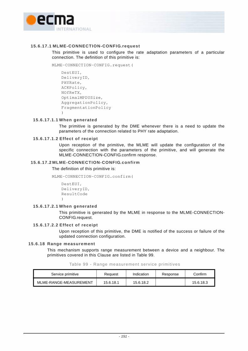
15.6.17.1 MLME-CONNECTION-CONFIG.requestThis primitive is used to configure the rate adaptation parameters of a particularconnection. The definition of this primitive is:
MLME-CONNECTION-CONFIG.request(
DestEUI,DeliveryID,PHYRate,ACKPolicy,NOfReTX,OptimalMPDUSize,AggregationPolicy,FragmentationPolicy)
15.6.17.1.1 When generatedThe primitive is generated by the DME whenever there is a need to update theparameters of the connection related to PHY rate adaptation.
15.6.17.1.2 Effect of receiptUpon reception of the primitive, the MLME will update the configuration of thespecific connection with the parameters of the primitive, and will generate theMLME-CONNECTION-CONFIG.confirm response.
15.6.17.2 MLME-CONNECTION-CONFIG.confirmThe definition of this primitive is:
MLME-CONNECTION-CONFIG.confirm(
DestEUI,DeliveryID,ResultCode)
15.6.17.2.1 When generatedThis primitive is generated by the MLME in response to the MLME-CONNECTION-CONFIG.request.
15.6.17.2.2 Effect of receiptUpon reception of this primitive, the DME is notified of the success or failure of theupdated connection configuration.
15.6.18 Range measurementThis mechanism supports range measurement between a device and a neighbour. Theprimitives covered in this Clause are listed in Table 99.
Table 99 - Range measurement service pr imit ives
Service primitive Request Indication Response Confirm
MLME-RANGE-MEASUREMENT 15.6.18.1 15.6.18.2 15.6.18.3
- 151 -

Table 100 defines the parameters used by the range measurement service primitives.
15.6.18.1 MLME-RANGE-MEASUREMENT.requestThis primitive is used to initiate one or more consecutive ranging measurements.
MLME-RANGE-MEASUREMENT.request(
DestEUI,RMN)
15.6.18.1.1 When generatedThe DME signals this primitive to the MLME to initiate range measurement with aneighbour of the device. Parameter RMN may be one (for a simple estimate) orgreater than one, so that the results of repeated measurements can be used toimprove accuracy.
15.6.18.1.2 Effect of receiptThe MLME generates frames to deliver over the medium to carry out the requestedrange measurements, and then delivers the result data to the DME.
15.6.18.2 MLME-RANGE-MEASUREMENT.indicationThis primitive is used to inform the DME that a range measurement request wasreceived.
MLME-RANGE-MEASUREMENT.indication(
SrcEUI,RMN)
15.6.18.2.1 When generatedThe MLME signals this primitive to the DME when it receives a range Measurementcommand frame with Range Type set to Range Measurement Request.
15.6.18.2.2 Effect of receiptThe DME is advised that a range measurement operation has started.
Table 100 - Range measurement parameters
Name Type Valid Range Description
Result Enumeration FAILURE, SUCCESS Indicates the result of the range measurement operation
LREnable Boolean FALSE, TRUE If TRUE, enable local range measurement, otherwise disable
DestEUI EUI-48 Any valid unicast EUI-48 Specifies the EUI-48 of the remote responding device
SrcEUI EUI-48 Any valid unicast EUI-48 Specifies the EUI-48 of the remote requesting device
RMN Integer 0 - 255 Number of measurements requested
MeasurementResultSet Array As described in Figure 55 Range measurement results
MeasurementResultSetCount Integer 0 - 255 Number of measurement results in MeasurementResultSet
- 152 -

15.6.18.3 MLME-RANGE-MEASUREMENT.confirmThis primitive reports the results of a range measurement operation.
MLME-RANGE-MEASUREMENT.confirm(
Result,MeasurementResultSet,MeasurementResultSetCount)
15.6.18.3.1 When generatedThe MLME signals this primitive to the DME when it has completed a requestedrange measurement operation.
15.6.18.3.2 Effect of receiptAs specified in Annex G, the DME may use a single measurement result to calculatea single range estimate. Local and remote ranging clock options may be used tocalculate confidence levels or error probabilities. Multiple measurements may beused to detect and correct for frequency errors between the local and remote clockfrequencies.
15.6.19 Application-specif ic command managementThe MAC sublayer provides application-specific command frames for sending controlinformation for the MAC client. At the sending device, command data is passed via theprimitives in this Clause, along with the parameters describing the attributes of thecommand, to the MAC sublayer for transfer to a peer MAC sublayer for unicast traffic or agroup of MAC entities for multicast or broadcast traffic. At the recipient device, the MACsublayer delivers received application-specific command data to the MAC client.
Application-specific commands may be fragmented for transfer between peer MACentities.
Application-specific commands may be transmitted using PCA or within DRP reservations.
The primitives covered in this Clause are listed in Table 101.
Table 101 - Appl icat ion-speci f ic command management pr imit ives
Service primitive Request Indication Response Confirm
MLME-AS-COMMAND 15.6.19.1 15.6.19.2 15.6.19.3
- 153 -

Table 102 lists the parameters that appear in the MLME-AS-COMMAND primitives definedin this Clause.
15.6.19.1 MLME-AS-COMMAND.requestThis primitive requests the transfer of an application-specific command to a peer MACsublayer or a group of peer MAC entities.
The definition of this primitive is:
MLME-AS-COMMAND.request(
DestEUI,TKID,ACKPolicy,TxTimeout,ASCommandData)
15.6.19.1.1 When generatedThis primitive is generated by the MAC client when an application-specific commandis to be transferred to a specified recipient.
15.6.19.1.2 Effect of receiptThe MAC sublayer attempts to transmit the application-specific command frameusing PCA or in a DRP reservation based on the other parameters provided in theprimitive. The MAC sublayer subsequently issues a MLME-AS-COMMAND.confirmto reflect the results.
15.6.19.2 MLME-AS-COMMAND.indicationThis primitive reports the reception of an application-specific command from a specifiedsender.
Table 102 - Appl icat ion-speci f ic command management parameters
Name Type Valid range Description
DestEUI EUI-48 Any valid EUI-48 Specifies the EUI-48 of the recipient device of the MCDU.
SrcEUI EUI-48 Any valid unicast EUI-48 Specifies the EUI-48 of the sending device of the MCDU.
TKID Integer Any valid TKID as defined in 16.2.6.1, or zero
Specifies a PTK or GTK used for protecting the MCDU. If zero, indicates no security protection for
this MCDU.
ACKPolicy Enumeration ACK, NO_ACK Specifies whether or not the MCDU requires acknowledgement.
TxTimeout Duration 0 - 65 535 Specifies the amount of time in milliseconds in which the MCDU needs to be successfully sent.
ASCommandData Array Variable Specifies the data passing the MLME-AS-COMMAND before transmission or after reception.
ResultCode Enumeration SUCCESS, TX_TIMEOUT,
OTHER_REASONS
Indicates the result of the MCDU transfer attempt.
- 154 -

The definition of this primitive is:
MLME-AS-COMMAND.indication(
SrcEUI,DestEUI,TKID,ACKPolicy,ASCommandData)
15.6.19.2.1 When generatedThis primitive is generated by the MAC sublayer to deliver to the MAC client acorrectly received valid application-specific command frame addressed to thisdevice.
15.6.19.2.2 Effect of receiptThe MAC client is provided with a valid application-specific command frameaddressed to this device from a specified sender.
15.6.19.3 MLME-AS-COMMAND.confirmThis primitive reports the result of an application-specific command frame transferattempt to a specified recipient.
The definition of this primitive is:
MLME-AS-COMMAND.confirm(
DestEUI,ResultCode)
15.6.19.3.1 When generatedThis primitive is generated by the MAC sublayer as a result of a MLME-AS-COMMAND.request to transfer an application-specific command frame to a specifiedrecipient.
15.6.19.3.2 Effect of receiptThe MAC client is notified of the results of the attempt by the MAC sublayer totransfer an application-specific command frame based on the parameters specifiedin an earlier MLME-AS-COMMAND.request.
15.7 MAC SAP interfaceThe MAC sublayer provides a data transfer service to the MAC client via the MAC SAP, thelogical data interface between the MAC client and the MAC sublayer. At the sending device,data is passed via the MAC SAP in MSDUs, along with the parameters describing theattributes of the MSDU, to the MAC sublayer for transfer to a peer MAC sublayer for unicasttraffic or a group of MAC entities for multicast or broadcast traffic. At the recipient device, theMAC sublayer delivers received data also in MSDUs to the MAC client.
Each MSDU is tagged with a user priority or stream index as indicated by the Delivery IDparameter passed along with the MSDU at the MAC SAP. There are eight levels for userpriority, and eight values for Stream Index designating up to eight possible streams betweenthe sender and recipient. Legal values for the Delivery ID parameter are in the range of 0 to15. A number in the range between 0 and 7, inclusive, denotes a user priority as defined bythe IEEE 802.1D priority tag. A number in the range between 8 and 15, inclusive, identifies astream from the sender to the recipient. The Delivery ID parameter is propagated across thewireless medium in the Delivery ID field of the Frame Control field of the MAC header.
- 155 -

Each device has an EUI-48 that, if non-NULL, uniquely identifies the device. This identifier isincluded in beacon frames, along with a 16-bit DevAddr selected by the device.
When an MSDU is delivered to the MAC sublayer by the MAC client, the device determinesthe DevAddr of the intended recipient based on the EUI-48 provided with the MSDU andinformation it receives in neighbours' beacons.
Before passing an MSDU to the MAC client, a device determines the EUI-48 of the sender ofthe MSDU using information it receives in neighbours' beacons.
All MSDUs labelled with the same Delivery ID and addressed to the same destination EUI-48are transmitted in the order in which they arrived at the local MAC SAP when they are subjectto the Imm-ACK or No-ACK acknowledgement policy. They may be transmitted out of orderdue to retries when the B-ACK acknowledgement policy is applied. However, MSDUs labelledwith different Delivery ID values and/or addressed to different destination EUI-48s are notnecessarily transmitted in the order in which they arrived at the local MAC SAP, since theMAC sublayer may reorder them for transmission based on their priorities and otherconsiderations or constraints.
MSDUs of the same Delivery ID received by the recipient MAC sublayer are released to theMAC client via the local MAC SAP in the same order as they arrived at the MAC SAP of thesending device. The recipient MAC sublayer delivers MSDUs bearing different Delivery IDvalues to the MAC client in a fashion that preserves the respective orders of the MSDUscarrying the same Delivery ID values.
MSDUs may be fragmented or aggregated for transfer between peer MAC entities, but arealways passed through the MAC SAP in whole MSDUs.
The MAC sublayer provides contention and reservation-based frame transfers. Contentionbased transfers use the prioritized contention access (PCA) method as specified in 17.2.3,while reservation-based transfers use the distributed reservation protocol (DRP) method asspecified in 17.2.4. MSDUs tagged with a user priority are transmitted using PCA. MSDUstagged with a Stream Index are transmitted primarily in a reservation and optionally by PCA.
The primitives covered in this Clause are listed in Table 103.
Table 103 - MAC-SAP pr imit ives
Service primitive Request Indication Response Confirm
MAC-DATA 15.7.1 15.7.2 15.7.3
- 156 -

Table 104 lists the parameters that appear in the MAC SAP primitives defined in this Clause.
15.7.1 MAC-DATA.requestThis primitive requests the transfer of an MSDU to a peer MAC sublayer or a group of peerMAC entities.
The definition of this primitive is:
MAC-DATA.request(
DestEUI,TKID,DeliveryID,TransmitTimeout,MSDU)
15.7.1.1 When generatedThis primitive is generated by the MAC client when an MSDU is to be transferred to aspecified recipient.
15.7.1.2 Effect of receiptThe MAC sublayer attempts to transmit the MSDU based on the other parametersprovided in the primitive. The MAC sublayer subsequently issues a MAC-DATA.confirmto reflect the results.
15.7.2 MAC-DATA.indicationThis primitive reports the reception of an MSDU from a specified sender.
The definition of this primitive is:
Table 104 - MAC-SAP pr imit ive parameters
Name Type Valid range Description
DestEUI EUI-48 Any valid EUI-48 Specifies the EUI-48 of the recipient device of the MSDU
SrcEUI EUI-48 Any valid unicast EUI-48 Specifies the EUI-48 of the sending device of the MSDU
TKID Integer Any valid TKID as defined in 16.2.6.1 or zero
Specifies a PTK or GTK used for protecting the MSDU. If zero, indicates no security protection for
this MSDU
DeliveryID Integer 0 - 15 Specifies the user priority of the MSDU for a value in range 0 through 7, or the stream index of the
MSDU for a value in range 8 through 15
TransmitTimeout Duration 0 - 65 535 Specifies the amount of time in milliseconds in which the MSDU needs to be successfully sent
MSDU Octet string Specifies the data passing the MAC SAP before transmission or after reception
ResultCode Enumeration SUCCESS, TRANSMIT_TIMEOUT,
OTHER_REASONS
Indicates the result of the MSDU transfer attempt
- 157 -

MAC-DATA.indication(
SrcEUI,DestEUI,TKID,DeliveryID,MSDU)
15.7.2.1 When generatedThis primitive is generated by the MAC sublayer to deliver to the MAC client a receivedMSDU addressed to this device.
15.7.2.2 Effect of receiptThe MAC client is provided with an MSDU addressed to this device from a specifiedsender.
15.7.3 MAC-DATA.confirmThis primitive reports the result of an MSDU transfer attempt to a specified recipient.
The definition of this primitive is:
MAC-DATA.confirm(
DestEUI,DeliveryID,ResultCode)
15.7.3.1 When generatedThis primitive is generated by the MAC sublayer as a result of a MAC-DATA.request totransfer an MSDU to a specified recipient.
15.7.3.2 Effect of receiptThe MAC client is notified of the results of the attempt by the MAC sublayer to transferan MSDU based on the parameters specified in an earlier MAC-DATA.request.
16 MAC frame formats
This Clause specifies the format of MAC frames. An overview of the MAC frame withdescriptions of common fields is followed by Clauses for each frame type and subtype. The finalClause contains a list of information elements that may appear in beacon frames and somecommand frames.
16.1 Frame format conventionsThe following conventions and definitions apply throughout this Clause.
16.1.1 FiguresMAC frames are described as a sequence of fields in a specific order. Figures in Clause 16depict fields in the order they are delivered to the PHY SAP, from left to right, where theleft-most field is transmitted first in time. In field figures, bits within the field are numberedfrom the least-significant bit on the right to the most-significant bit on the left.
An example sequence of fields is defined in Figure 33.
- 158 -

16.1.2 Octet orderUnless otherwise noted, fields longer than a single octet are delivered to the PHY SAP inorder from the octet containing the least-significant bits to the octet containing the most-significant bits.
An example of a bitmap specification for a two-octet field is defined in Figure 34.
16.1.3 EncodingValues specified in decimal are encoded in unsigned binary unless otherwise stated.
A bitmap is a sequence of bits, labelled as bit[0] through bit[N-1]. A bitmap is encoded in afield such that bit[0] corresponds to the least-significant bit of the field and subsequentbitmap elements correspond to subsequent significant bits of the field. Octets of the fieldare presented to the PHY SAP in order from least-significant octet to most-significantoctet.
Reserved fields and subfields are set to zero on transmission and ignored on reception.Fields and subfields are not set to reserved values on transmission. Unless otherwisenoted, fields or subfields that are set to reserved values or are defined based on otherfields or subfields that are set to reserved values are ignored on reception.
16.2 General MAC frame formatA MAC frame consists of a fixed-length MAC Header and an optional variable-length MACFrame Body. The MAC Header is defined in Figure 35.
octets: 2 1 … 4
First field transmitted (2 octets) Second field transmitted (1 octet) … Last field transmitted (4 octets)
Figure 33 - Example sequence of fields
bits: b15-b13 b12-b8 b7-b0
Most-significant bits of second octet transmitted Least-significant bits of second octet transmitted First octet transmitted
Figure 34 - Example bitmap specification for a field
octets: 2 2 2 2 2
Frame Control DestAddr SrcAddr Sequence Control Access Information
Figure 35 - MAC Header format
- 159 -

The MAC Frame Body, when present, contains a Frame Payload and Frame CheckSequence (FCS) as defined in Figure 36.
In secure frames the Frame Payload includes security fields as defined in Figure 37. The left-most four fields in Figure 37 are collectively referred to as the Security Header.
The Frame Payload length ranges from zero to pMaxFramePayloadSize. If the FramePayload length is zero, the FCS field is not included, and there is no MAC Frame Body. TheFrame Payload length includes the length of the security fields for a secure frame.
In this Clause, a reference to the payload of a frame indicates the Frame Payload field of anon-secure frame, or the Secure Payload field of a secure frame. The payload is a sequenceof octets labelled as payload[0] through payload[P-1]. Octets are passed to the PHY SAP inascending index-value order.
16.2.1 Frame controlThe Frame Control field is defined in Figure 38.
16.2.1.1 Protocol versionThe Protocol Version field is invariant in size and placement across all revisions of thisStandard. For this revision of the Standard, Protocol Version is set to zero. All othervalues are reserved.
16.2.1.2 SecureThe Secure bit is set to ONE in a secure frame, which is protected using the temporalkey specified by the Temporal Key Identifier (TKID). The Secure bit is set to ZEROotherwise. Frames with the Secure bit set to ONE use the Frame Payload format forsecure frames as defined in Figure 37. Valid settings for the Secure bit in each frametype are listed in Table 131 in 18.2.
16.2.1.3 ACK policyThe ACK Policy field is set to the type of acknowledgement requested by the transmitter.Acknowledgement procedures are described in 17.8. The allowed values for the ACKPolicy field are defined in Table 105.
octets: Ln 4
Frame Payload FCS
Figure 36 - MAC Frame Body format
octets: 3 1 2 6 P 8
Temporal Key Identifier (TKID)
Security Reserved
Encryption Offset (EO)
Secure Frame Number (SFN)
Secure Payload
Message Integrity Code (MIC)
Figure 37 - Frame Payload field format for secure frames
bits: b15-b14 b13 b12-b9 b8-b6 b5-b4 b3 b2-b0
Reserved Retry Frame Subtype / Delivery ID Frame Type ACK Policy Secure Protocol Version
Figure 38 - Frame Control field format
- 160 -

16.2.1.4 Frame typeThe Frame Type field is set to the type of frame that is being sent. Table 106 lists thevalid frame type values, descriptions, and the Clauses that describe the format and useof each of the individual frame types.
16.2.1.5 Frame subtype / del ivery IDThe Frame Subtype / Delivery ID field is used to assist a receiver in the properprocessing of received frames. In control or command frames, this field is used asFrame Subtype, as defined in Table 110 in 16.4 and Table 112 in 16.5. In data framesand aggregated data frames, this field is used as Delivery ID as defined in Table 107.
This field is reserved in all other frame types.
Table 105 - ACK Pol icy f ie ld encoding
Value ACK policy type Description
0 No-ACK The recipient(s) do not acknowledge the transmission, and the sender treats the transmission as successful without regard for the actual result. The use
of this policy is defined in 17.8.1.
1 Imm-ACK The addressed recipient returns an Imm-ACK frame after correct reception, according to the procedures defined in 17.8.2.
2 B-ACK The addressed recipient keeps track of the frames received with this policy until requested to respond with a B-ACK frame, according to the procedures
defined in 17.8.3.
3 B-ACK Request The addressed recipient returns a B-ACK frame after reception, according to the procedures defined in 17.8.3.
Table 106 - Frame type f ie ld encoding
Value Frame type Clause
0 Beacon frame 16.3
1 Control frame 16.4
2 Command frame 16.5
3 Data frame 16.6
4 Aggregated data frame 16.7
5 - 7 Reserved
Table 107 - Del ivery ID encoding in Frame Control
b12 b11-b9
0 User Priority
1 Stream Index
- 161 -
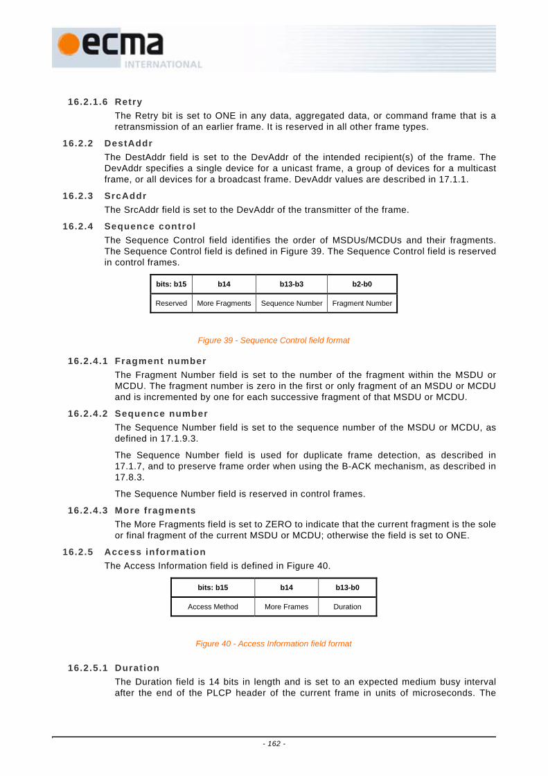
16.2.1.6 RetryThe Retry bit is set to ONE in any data, aggregated data, or command frame that is aretransmission of an earlier frame. It is reserved in all other frame types.
16.2.2 DestAddrThe DestAddr field is set to the DevAddr of the intended recipient(s) of the frame. TheDevAddr specifies a single device for a unicast frame, a group of devices for a multicastframe, or all devices for a broadcast frame. DevAddr values are described in 17.1.1.
16.2.3 SrcAddrThe SrcAddr field is set to the DevAddr of the transmitter of the frame.
16.2.4 Sequence controlThe Sequence Control field identifies the order of MSDUs/MCDUs and their fragments.The Sequence Control field is defined in Figure 39. The Sequence Control field is reservedin control frames.
16.2.4.1 Fragment numberThe Fragment Number field is set to the number of the fragment within the MSDU orMCDU. The fragment number is zero in the first or only fragment of an MSDU or MCDUand is incremented by one for each successive fragment of that MSDU or MCDU.
16.2.4.2 Sequence numberThe Sequence Number field is set to the sequence number of the MSDU or MCDU, asdefined in 17.1.9.3.
The Sequence Number field is used for duplicate frame detection, as described in17.1.7, and to preserve frame order when using the B-ACK mechanism, as described in17.8.3.
The Sequence Number field is reserved in control frames.
16.2.4.3 More fragmentsThe More Fragments field is set to ZERO to indicate that the current fragment is the soleor final fragment of the current MSDU or MCDU; otherwise the field is set to ONE.
16.2.5 Access informationThe Access Information field is defined in Figure 40.
16.2.5.1 DurationThe Duration field is 14 bits in length and is set to an expected medium busy intervalafter the end of the PLCP header of the current frame in units of microseconds. The
bits: b15 b14 b13-b3 b2-b0
Reserved More Fragments Sequence Number Fragment Number
Figure 39 - Sequence Control field format
bits: b15 b14 b13-b0
Access Method More Frames Duration
Figure 40 - Access Information field format
- 162 -

duration value is set as defined in 17.1.9.1 and used to update the network allocationvector (NAV) according to the procedures defined in 17.3.2.
16.2.5.2 More framesIn frames sent with the Access Method bit set to ONE, the More Frames bit is set toZERO if the transmitter will not send further frames to the same recipient during thecurrent reservation block; otherwise it is set to ONE.
In frames sent with the Access Method bit set to ZERO, the More Frames bit is set toZERO if the transmitter will not send further frames to the same recipient during thecurrent superframe; otherwise it is set to ONE.
The More Frames bit is reserved in beacon and control frames. Additional rulesregarding the More Frames field are specified in 17.1.9.2.
16.2.5.3 Access methodThe Access Method bit is set to ONE in all frames transmitted within a hard or privateDRP reservation block by the reservation owner or target prior to the release of thereservation block, including the UDA and UDR control frames that release thereservation block.
The Access Method bit may be set to ONE in frames transmitted within a Soft DRPreservation block without backoff by the reservation owner.
The Access Method bit in an Imm-ACK, B-ACK or CTS control frame is set to the samevalue as the Access Method bit in the corresponding received frame.
The Access Method bit is set to ZERO in frames transmitted at all other times, otherthan in beacon frames.
The Access Method bit is reserved in beacon frames.
16.2.6 Frame payloadThe Frame Payload field is a variable length field that carries the information that is to betransferred to a device or group of devices. In a secure frame, it includes the requiredsecurity fields as defined in Figure 37 and defined below.
16.2.6.1 Temporal key identif ier (TKID)The TKID field is an identifier for the temporal key used to protect the frame. The TKIDuniquely identifies this key from any other temporal keys held by the sender and therecipient(s) of the frame. It does not need to uniquely identify the key for devices notholding the key.
16.2.6.2 Security reservedThe Security Reserved field is reserved, but included in authentication of the frame.
16.2.6.3 Encryption offset (EO)The Encryption Offset field indicates where encryption starts, in octets, relative to thebeginning of the Secure Payload, as defined in Figure 37. A value of zero indicates thatthe entire Secure Payload is encrypted. A non-zero value in this field indicates that thefirst EO octets of the Security Payload are not encrypted. Regardless of the value of thisfield, the entire Secure Payload, along with other appropriate fields, is authenticated bythe MIC.
16.2.6.4 Secure frame number (SFN)The SFN field provides message freshness as a defence against replay attacks. TheSFN field in a secure frame is set to the next value of the sender's secure frame counter(SFC) for the temporal key used by this frame. SFC setting and replay protection aredescribed in 18.4.2.
- 163 -

16.2.6.5 Secure payloadThe Secure Payload field in secure frames is the counterpart of the Frame Payload fieldin non-secure frames. It contains the information specific to individual frame types andprotected by the symmetric key identified in the TKID field of the same frame.
16.2.6.6 Message integrity code (MIC)The MIC field contains an 8-octet cryptographic checksum used to protect the integrityof the MAC Header and Frame Payload.
16.2.7 FCSThe FCS field contains a 32-bit value that represents a CRC polynomial of degree 31.
The CRC is calculated over a calculation field, which is the entire Frame Payload field forthis specification. The calculation field is mapped to a message polynomial M(x) of degreek-1, where k is the number of bits in the calculation field. The least-significant bit of the firstoctet presented to the PHY SAP is the coefficient of the xk-1 term, and the most-significantbit of the last octet transmitted is the coefficient of the x0 term.
The CRC is calculated using the following Standard generator polynomial of degree 32:
G(x) = x32 + x26 + x23 + x22 + x16 + x12 + x11 + x10 + x8 + x7 + x5 + x4 + x2 + x + 1
The CRC polynomial is the one's complement of the modulo 2 sum of the followingremainders:
- The remainder resulting from xk × (x31 + x30 + ... + x + 1) divided (modulo 2) by G(x).
- The remainder resulting from x32 × M(x), divided (modulo 2) by G(x).
The FCS field value is derived from the CRC polynomial such that the least-significant bitis the coefficient of the x31 term and the most-significant bit is the coefficient of the x0 term.Figure 41 defines the encoding of the FCS field for the CRC polynomial:
a31x31 + a30x30 + a29x29 + … + a2x2 + a1x + a0
In a common implementation, at the transmitter, the initial remainder of the division ispreset to all ONEs and is then modified via division of the calculation field by the generatorpolynomial G(x). The one’s complement of this remainder is the FCS field. At the receiver,the initial remainder is preset to all ONEs. The serial incoming bits of the calculation fieldand FCS, when divided by G(x) in the absence of transmission errors, results in a uniquenon-zero remainder value. The unique remainder value is the polynomial:
x31 + x30 + x26 + x25 + x24 + x18 + x15 + x14 + x12 + x11 + x10 + x8 + x6 + x5 + x4 + x3 + x + 1
bits: b31 b30 b29 … b2 b1 b0
a0 a1 a2 … a29 a30 a31
Figure 41 - FCS field encoding
- 164 -
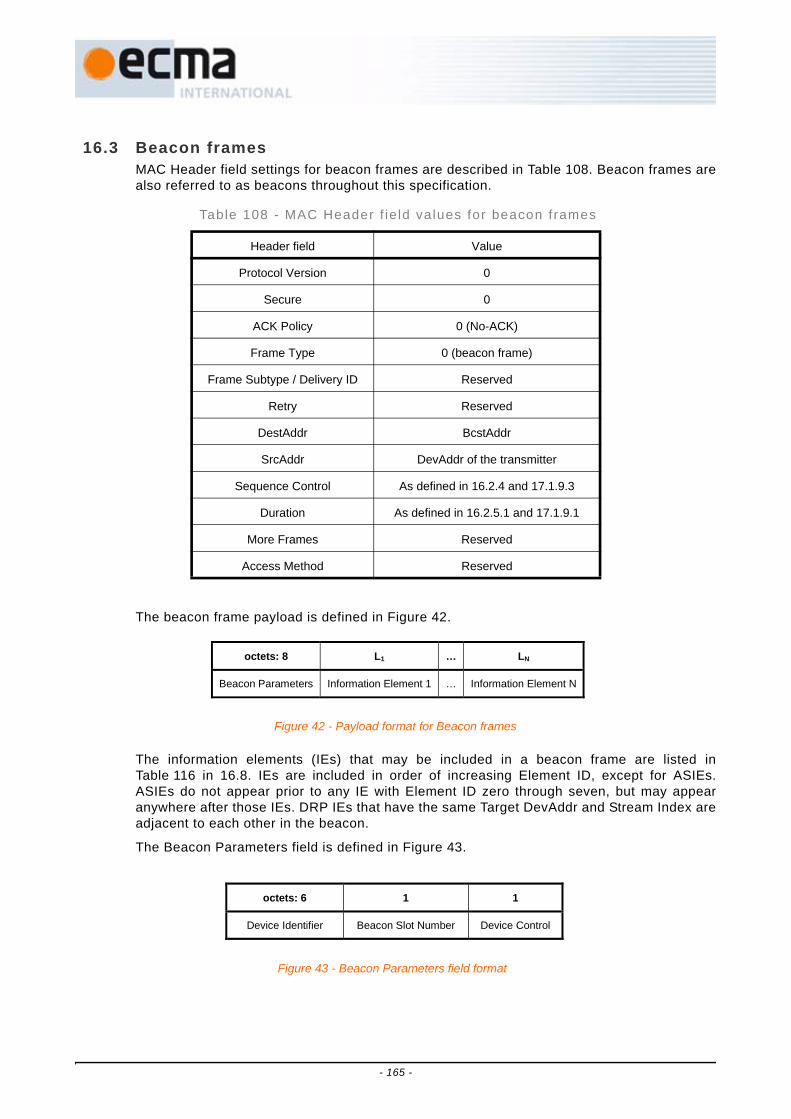
16.3 Beacon framesMAC Header field settings for beacon frames are described in Table 108. Beacon frames arealso referred to as beacons throughout this specification.
The beacon frame payload is defined in Figure 42.
The information elements (IEs) that may be included in a beacon frame are listed inTable 116 in 16.8. IEs are included in order of increasing Element ID, except for ASIEs.ASIEs do not appear prior to any IE with Element ID zero through seven, but may appearanywhere after those IEs. DRP IEs that have the same Target DevAddr and Stream Index areadjacent to each other in the beacon.
The Beacon Parameters field is defined in Figure 43.
Table 108 - MAC Header f ie ld values for beacon frames
Header field Value
Protocol Version 0
Secure 0
ACK Policy 0 (No-ACK)
Frame Type 0 (beacon frame)
Frame Subtype / Delivery ID Reserved
Retry Reserved
DestAddr BcstAddr
SrcAddr DevAddr of the transmitter
Sequence Control As defined in 16.2.4 and 17.1.9.3
Duration As defined in 16.2.5.1 and 17.1.9.1
More Frames Reserved
Access Method Reserved
octets: 8 L1 … LN
Beacon Parameters Information Element 1 … Information Element N
Figure 42 - Payload format for Beacon frames
octets: 6 1 1
Device Identifier Beacon Slot Number Device Control
Figure 43 - Beacon Parameters field format
- 165 -

The Device Identifier field is set to the EUI-48 [H1] of the device sending the beacon. Adevice may use a NULL EUI-48 value (all bits set to ONE) to indicate it does not have aunique EUI-48 value.The EUI is a sequence of 6 octets, labelled as eui[0] through eui[5]. Thefirst three octets (eui[0] through eui[2]) are the manufacturer's OUI, and the last three octets(eui[3] through eui[5]) are the manufacturer-selected extension identifier. Octets of the EUIare passed to the PHY SAP in ascending index-value order.
The Beacon Slot Number field is set to the number of the beacon slot where the beacon issent within the beacon period (BP), in the range of [0, mMaxBPLength-1], except in beaconssent in signaling slots. In signaling slots it is set to the number of the device's non-signalingbeacon slot.
The Device Control field is defined in Figure 44.
The Movable bit is set to ONE if the beacon is movable according to 17.2.5, and is set toZERO otherwise.
The Signaling Slot bit is set to ONE if the beacon is sent in a signaling beacon slot accordingto 17.2.3, and is set to ZERO otherwise.
The Security Mode field is set to the security mode at which the device is currently operating.
16.4 Control framesDefault MAC Header field settings for control frames are listed in Table 109. Specific MACHeader field settings and payload descriptions for each of the control frames are defined inthe following Clauses.
Table 109 - MAC Header f ie ld values for control f rames
Header field Value
Protocol Version 0
Secure As defined in 16.2.1.2
ACK Policy 0 (No-ACK)
Frame Type 1 (control frame)
Frame Subtype Value from Table 110
Retry Reserved
DestAddr DevAddr of the recipient
SrcAddr DevAddr of the transmitter
Sequence Control Reserved
Duration As described in 16.2.5.1 and 17.1.9.1
More Frames Reserved
Access Method As described in 16.2.5.3
bits: b7-b6 b5-b2 b1 b0
Security Mode Reserved Signaling Slot Movable
Figure 44 - Device Control field format
- 166 -

Table 110 lists valid values for the Frame Subtype field for control frames.
16.4.1 Immediate acknowledgement ( Imm-ACK)In Imm-ACK frames, the DestAddr field is set to the SrcAddr of the received frame that isacknowledged. Imm-ACK frames have no frame payload.
16.4.2 Block acknowledgement (B-ACK)In B-ACK frames, the DestAddr field is set to the SrcAddr of the frame that requested theB-ACK.
The B-ACK frame acknowledges correct or incorrect receipt of the previous sequence offrames and provides information for the transmission of the next sequence of frames asdescribed in 17.8.3. The B-ACK frame payload is defined in Figure 45.
The Buffer Size field specifies the maximum number of octets in the sum of the framepayloads of all frames in the next B-ACK sequence.
The Frame Count field specifies the maximum number of frames in the next B-ACKsequence.
Table 110 - Frame Subtype f ie ld encoding for control f rames
Value Control frame subtype Description
0 Imm-ACK Acknowledges correct receipt of the previously-received frame
1 B-ACK Acknowledges correct or incorrect receipt of one or more preceding frames
2 RTS Announces to a recipient device that a frame is ready for transmission and requests
confirmation of ability to receive
3 CTS Responds to an RTS control frame that the recipient is able to receive
4 UDA Announces to neighbours of the transmitting device that the remainder of a reservation block it owns is available for use by other
devices via PCA
5 UDR Announces to neighbours of the transmitting device that the remainder of a reservation
block of which it is the target is available for use by other devices via PCA
6 - 13 Reserved Reserved
14 Application-specific At discretion of application owner
15 Reserved Reserved
octets: 2 1 1 2 0-n
Buffer Size Frame Count Reserved Sequence Control Frame Bitmap
Figure 45 - Payload format for B-ACK frames
- 167 -

The Sequence Control and Frame Bitmap fields together specify an acknowledgementwindow of MSDU fragments and their reception status. The Sequence Control fieldspecifies the Sequence Number and Fragment Number that start the acknowledgementwindow.
The Frame Bitmap field varies in length. A zero-length Frame Bitmap field indicates anacknowledgement window of length zero. Otherwise, the least-significant octet of theFrame Bitmap field corresponds to the MSDU indicated by the Sequence Control field, andeach bit of the octet corresponds to a fragment of that MSDU. The least-significant bit ineach octet corresponds to the first fragment and successive bits correspond to successivefragments. Successive octets present in the Frame Bitmap field correspond to successiveMSDUs, and each bit corresponds to a fragment of the MSDU. The acknowledgementwindow ends at fragment seven of the MSDU that corresponds to the most-significant octetin the Frame Bitmap.
For all bits within the Frame Bitmap, a value of ONE indicates that the correspondingfragment was received in either the current sequence or an earlier one. A value of ZEROindicates that the corresponding fragment was not received in the current sequence(although it may have been received in an earlier one). Bits of the least-significant octet ofthe Frame Bitmap field corresponding to fragments prior to the start of theacknowledgement window are undefined. Frames with a Sequence Number earlier thanthe Sequence Number indicated in the Sequence Control field were not received in the lastB-ACK sequence. Such frames were previously received or are no longer expected.
16.4.3 Request to send (RTS)In RTS frames, the DestAddr field is set to the DevAddr of the device to receive thefollowing frame from the transmitter. RTS frames have no frame payload.
16.4.4 Clear to send (CTS)In CTS frames, the DestAddr field is set to the SrcAddr of the received RTS frame. CTSframes have no frame payload.
16.4.5 Unused DRP reservat ion announcement (UDA)The UDA frame is used to explicitly release the remaining time of the current Hard orPrivate DRP reservation block. The DestAddr field is set to BcstAddr.
The UDA frame payload includes a list of DevAddrs of the devices that will respond with aUDR frame, as defined in Figure 47.
bits: b15-14 b13-b3 b2-b0
Reserved Sequence Number Fragment Number
Figure 46 - Sequence Control field format
octets: 2 … 2
DevAddr 1 … DevAddr N
Figure 47 - Payload format for UDA frames
- 168 -

16.4.6 Unused DRP reservation response (UDR)The UDR frame is used to respond to UDA frames to explicitly release the remaining timeof the current Hard or Private DRP reservation block. The DestAddr field is set to theSrcAddr of the received UDA frame. UDR frames have no frame payload.
16.4.7 Application-specif icThe payload format for Application-specific control frames is defined in Figure 48.
The Specifier ID field is set to a 16-bit value that identifies a company or organization. SeeAnnex C. The owner of the Specifier ID defines the format and use of the Data field.
16.5 Command framesDefault MAC Header settings for command frames are defined in Table 111.
Table 111 - Default MAC Header f ie ld values for command frames
Header field Value
Protocol Version 0
Secure As defined in 16.2.1.2
ACK Policy 0 (No-ACK) or 1 (Imm-ACK)
Frame Type 2 (command frame)
Frame Subtype Value from Table 112
Retry As defined in 16.2.1.6
DestAddr DevAddr of the recipient
SrcAddr DevAddr of the transmitter
Sequence Control As defined in 16.2.4
Duration As defined in 16.2.5.1 and 17.1.9.1
More Frames As defined in 16.2.5.2
Access Method As defined in 16.2.5.3
octets: 2 …
Specifier ID Data
Figure 48 - Payload format for Application-specific control frames
- 169 -

Table 112 contains a list of valid values for the Frame Subtype field for command frames.
16.5.1 DRP reservation requestThe DRP Reservation Request command frame is used to create or modify a DRPreservation. The DRP Reservation Request command frame payload is defined inFigure 49.
Each DRP IE field included in the command frame corresponds to a reservation requestidentified by the Target/Owner DevAddr, Stream Index, and Reservation Type in the IE.The DRP IE is defined in 16.8.6.
Table 112 - Frame Subtype f ie ld encoding for Command frames
Value Command frame subtype Description
0 DRP Reservation Request Used to request creation or modification of a DRP reservation
1 DRP Reservation Response Used to respond to a DRP reservation request command
2 Probe Used to request for, or respond with, information elements
3 Pair-wise Temporal Key (PTK) Used to derive a PTK via a 4-way handshake between two devices
4 Group Temporal Key (GTK) Used to solicit or distribute a GTK within a secure relationship
5 Range Measurement Used to exchange timing information for range measurement
6 - 13 Reserved Reserved
14 Application-specific At discretion of application owner
15 Reserved Reserved
octets: M1 M2 … MN
DRP IE-1 DRP IE-2 … DRP IE-N
Figure 49 - Payload format for DRP Reservation Request command frames
- 170 -

16.5.2 DRP reservation responseThe DRP Reservation Response command frame is used to respond to a DRP ReservationRequest command frame. The DRP Reservation Response command frame payload isdefined in Figure 50.
The DRP Reservation Response command frame includes all the DRP IEs from thereservation request. The DRP Availability IE is included according to the rules defined in17.4.
16.5.3 ProbeThe Probe command frame is used to request information from a device or respond to aProbe request. The payload format is defined in Figure 51.
If the payload includes a Probe IE, the command requests information from the recipient.Each Information Element field contains one information element.
16.5.4 Pairwise temporal key (PTK)The PTK command frame is used in a 4-way handshake by a pair of devices, as describedin 18.3.1, to authenticate each other and to derive a shared symmetric PTK for securingcertain unicast traffic between the two devices. The PTK command frame is defined inFigure 52.
The Message Number is set to 1, 2, 3, or 4, respectively, in the PTK command containingthe first, second, third, or fourth message of the 4-way handshake. The other values of thisfield are reserved.
octets: M1 M2 … MN 2 to 34
DRP IE-1 DRP IE-2 … DRP IE-N DRP Availability IE
Figure 50 - Payload format for DRP Reservation Response command frames
Octets: M1 M2 … MN
Information Element 1 Information Element 2 … Information Element N
Figure 51 - Payload format for Probe command frames
octets: 1 1 3 11 16 16 8
Message Number
Status Code
PTKID Reserved MKID I-Nonce / R-Nonce
PTK MIC
Figure 52 - Payload format for PTK command frames
- 171 -

The Status Code in a PTK command indicates the current status of the 4-way handshakeat the device sending this command. It is encoded as defined in Table 113.
The PTKID is set to a non-zero number as the TKID of the PTK to be derived from this 4-way handshake procedure. The initiator of the 4-way handshake chooses this value afterdetermining that this value is different from the TKID of the PTK, if any, that is to bereplaced by the new PTK, and the TKID of any PTK or GTK it currently possesses.
The MKID identifies the master key used in this 4-way handshake as described in 18.3.1.
The I-Nonce/R-Nonce is a random number generated by the initiator or responder for this4-way handshake. This field is set to I-Nonce, the random number generated by theinitiator in the command containing a Message Number of 1 or 3, and is set to R-Nonce,the random number generated by the responder in the command containing a MessageNumber of 2 or 4.
The PTK MIC in the PTK command containing a Message Number of 1 is set to zero ontransmission and is ignored on reception.
The PTK MIC in the PTK command containing a Message Number of 2, 3, or 4 is set to theMIC that protects the fields in the payload of this command using the KCK generated fromthe first two messages of the 4-way handshake as specified in 18.3.1.
The MAC Header for the PTK command frame is set as indicated in Table 111, with theACK Policy set to Imm-ACK.
16.5.5 Group temporal key (GTK)The GTK command frame is used to solicit or distribute a GTK following a PTK update.The GTK is used to secure certain multicast traffic from a sending device to a group ofrecipient devices, and is chosen by the sending device. The GTK command frame isalways in secure form, and the Secure Payload field is defined in Figure 53.
Table 113 - Status Code f ie ld encoding in PTK commands
Value Meaning
0 Normal-the 4-way handshake proceeds
1 Aborted-the 4-way handshake is aborted per security policy
2 Aborted-the 4-way handshake is aborted in order to yield to a concurrent 4-way handshake using
the same master key
3 PTKID not accepted-it is the TKID of a PTK or GTK being possessed by this device
4 - 255 Reserved
octets: 1 1 3 3 2 6 16
Message Number
Status Code
GTKID Reserved GroupAddr GTK SFC GTK
Figure 53 - Payload format for GTK command frames
- 172 -

The Message Number is set to 0 in the GTK command transmitted by a multicast recipientdevice to solicit a new GTK from a multicast sender. The Message Number is set to 1 inthe GTK command transmitted by a multicast sender to distribute a new GTK to a multicastrecipient. The Message Number is set to 2 in the GTK command transmitted by a multicastrecipient device to respond to the distribution of a new GTK command.
The Status Code in a GTK command indicates the current status of the GTK solicitation ordistribution at the device sending this command. It is encoded as defined in Table 114.
The GTKID in the GTK command containing a Message Number of 0 is set to the TKID ofthe GTK being solicited. It is set to zero if the soliciting device does not know the TKID ofthe GTK it is soliciting.
The GTKID in the GTK command containing a Message Number of 1 is set to a non-zeronumber as the TKID of the GTK being distributed. The distributor chooses this value afterdetermining that this value is different from the TKID of the GTK, if any, that is to bereplaced by the new GTK, and the TKID of any PTK or GTK the distributor or recipientcurrently possesses.
The GTKID in the GTK command containing a Message Number of 2 is set to the GTKID inthe last received GTK command containing a Message Number of 1.
The GroupAddr is set to the McstAddr or BcstAddr for which the GTK is being solicited ordistributed. It is set to 0x0001 if the GTK is applied to all broadcast and multicast trafficfrom the device distributing this GTK.
The GTK SFC in the GTK command containing a Message Number of 0 is set to zero ontransmission and ignored on reception.
The GTK SFC in the GTK command containing a Message Number of 1 is set to thecurrent value of the secure frame counter set up for the GTK being distributed.
The GTK SFC in the GTK command containing a Message Number of 2 is set to the GTKSFC in the last received GTK command containing a Message Number of 1.
The GTK is the GTK distributed by the multicast sender for the McstAddr. In a GTKcommand soliciting a GTK, the GTK is set to zero prior to encryption.
The MAC Header for the GTK command frame is set as indicated in Table 111, with theACK Policy set to Imm-ACK.
16.5.6 Range measurementThe Range measurement command frame payload is defined in Figure 54.
Table 114 - Status Code f ie ld encoding in GTK commands
Value Meaning
0 Normal-GTK solicitation or distribution proceeds
1 Rejected-GTK solicitation or distribution is rejected per security policy
2 GTKID not accepted-it is the TKID of a PTK or GTK being possessed by this device
3 - 255 Reserved
- 173 -

The Range Payload field format definition depends on the Range Type as defined inTable 115.
The Range Payload field for Range Measurement Request type is defined in Figure 55.
The Requested Measurement Number field contains the number of consecutive two-waytime transfer measurements.
The Range Payload field for Range Measurement type contains zero octets.
The Range Payload field for Range Measurement Report type is defined in Figure 56.
The Measurement Count field indicates the number of measurements reported.
The Range Supported field is defined in Figure 57, and indicates range measurementsupport and range measurement precision. Bits are set to ONE to indicate support or toZERO to indicate the feature is not supported.
Table 115 - Range Type f ie ld encoding
Value Range Payload
0 Range Measurement Request
1 Range Measurement
2 Range Measurement Report
3 - 255 Reserved
octets: 1 N
Range Type Range Payload
Figure 54 - Payload format for Range Measurement command frames
octets: 1
Requested Measurement Number
Figure 55 - Range Payload field format for Range Measurement Request type
octets: 1 1 1 4 4 … 4 4
Measurement Count Range Supported PHYClockAccuracy R1C1 T2C1 … R1CN T2CN
Figure 56 - Range Payload field format for Range Measurement Report type
- 174 -

PHYClockAccuracy indicates the accuracy of the PHY clock in units of ppm.
Each pair of R1C and T2C fields contains the range measurement reception timer andrange measurement transmission timer value respectively.
16.5.7 Application-specif icThe payload format for Application-specific command frames is defined in Figure 58.
The Specifier ID field is set to a 16-bit value that identifies a company or organization. SeeAnnex C. The owner of the Specifier ID defines the format and use of the Data field.
16.6 Data framesMAC Header and Frame Payload fields in data frames are set as described in 16.2.
16.7 Aggregated data framesIn aggregated data frames, the payload contains an Aggregation Header and multipleMSDUs, each aligned to a 4-octet boundary. The aggregated data frame payload is defined inFigure 59.
The Frame Payload size for aggregated data frames is subject to the same maximum size asany Frame Payload.
The Aggregation Header field is defined in Figure 60.
bits: b7 b6 b5 b4 b3 b2 b1 b0
Reserved 32-bit counter
supported
24-bit counter
supported
4 224 MHz sample
precision
2 112 MHz sample
precision
1 056 MHz sample
precision
528 MHz sample
precision
Range measurements
supported
Figure 57 - Range Supported field format
octets: 2 …
Specifier ID Data
Figure 58 - Payload format for Application-specific command frame
octets: 2+(2×N) 0 or 2 M1 0-3 M2 0-3 … MN
Aggregation Header
Pad to 4-octet boundary
MSDU 1
Pad to 4-octet boundary
MSDU 2
Pad to 4-octet boundary
… MSDU N
Figure 59 - Payload format for aggregated data frames
- 175 -

The MSDU Count field contains the number of MSDUs included in the aggregated frame.
The Length fields in the Aggregation Header field indicate the length in octets of thecorresponding MSDUs. The lengths do not include the Pad octets.
16.8 Information elementsThis Clause defines the information elements (IEs) that can appear in beacons and certaincommand frames.
The general format of all IEs is defined in Figure 61.
The Element ID field is set to the value as listed in Table 116 that identifies the informationelement.
The Length field is set to the length, in octets, of the IE-specific fields that follow.
The IE-specific fields contain information specific to the IE.
Table 116 contains a list of IEs defined in this Standard.
Table 116 - Informat ion elements
Element ID Information element Description
0 Traffic Indication Map (TIM) IE Indicates that a device has data buffered for transmission via PCA
1 Beacon Period Occupancy IE (BPOIE)
Provides information on neighbours' BP occupancy in the previous superframe
2 PCA Availability IE Indicates the MASs that a device is available to receive PCA frames and transmit the required response
3 - 7 Reserved Reserved
8 DRP Availability IE Indicates a device's availability for new DRP reservations
9 Distributed Reservation Protocol (DRP) IE
Indicates a reservation with another device
10 Hibernation Mode IE Indicates the device will go to hibernation mode for one or more superframes but intends to wake at a specified time in the future
octets: 1 1 2 … 2
MSDU Count Reserved Length of MSDU 1 … Length of MSDU N
Figure 60 - Aggregation Header field format
octets: 1 1 N
Element ID Length (=N) IE-specific fields
Figure 61 - General IE format
- 176 -

11 BP Switch IE Indicates the device will change its BPST at a specified future time
12 MAC Capabilities IE Indicates which MAC capabilities a device supports
13 PHY Capabilities IE Indicates which PHY capabilities a device supports
14 Probe IE Indicates a device is requesting one or more IEs from another device or/and responding with requested IEs
15 Application-specific Probe IE Indicates a device is requesting an Application-specific IE from another device
16 Link Feedback IE Provides data rate and power control feedback
17 Hibernation Anchor IE Provides information on devices in hibernation mode
18 Channel Change IE Indicates a device will change to another channel
19 Identification IE Provides identifying information about the device, including a name string
20 Master Key Identifier (MKID) IE Identifies some or all of the master keys held by the transmitting device
21 Relinquish Request IE Indicates that a neighbour requests that a device release one or more MASs from its reservations
22 Multicast Address Binding (MAB) IE
Indicates an address binding between a multicast EUI-48 and a McstAddr
23 Tone-nulling IE Announces tone-nulling information for DAA operation
24 Regulatory Domain IE Announces regulatory domain information
25 - 249 Reserved Reserved
250 WiMedia Logical Link Control Protocol IE
251 WiMedia Platform Test IE
252 Bluetooth Protocol IE For use by Bluetooth protocols
253 - 254 Reserved Reserved
255 Application-Specific IE (ASIE) Use varies depending on the application
Table 116 - In format ion elements (concluded)
Element ID Information element Description
- 177 -

16.8.1 Application-specif ic IE (ASIE)The ASIE is defined in Figure 62.
The Specifier ID field is set to a 16-bit value that identifies a company or organization. SeeAnnex C.
The owner of the Specifier ID defines the format and use of the Application-specific Datafield.
16.8.2 Application-specif ic probe IEThe Application-specific Probe IE is used to request an application-specific IE from adevice. It is defined in Figure 63.
The Target DevAddr field is set to the DevAddr of the device from which an ASIE isrequested.
The Specifier ID is set to a 16-bit value that identifies a company or organization. SeeAnnex C.
The owner of the Specifier ID defines the format and use of the Application-specificRequest Information field.
16.8.3 Beacon period occupancy IE (BPOIE)The BPOIE provides information on the BP observed by the device sending the IE. TheBPOIE is defined in Figure 64.
The BP Length field is set to the length of the BP, measured in beacon slots, as defined in17.2.2.
The Beacon Slot Info Bitmap field consists of K octets of 2-bit elements to indicate thebeacon slot occupancy and movability in the BP, where K = Ceiling (BP_Length/4). Eachelement n, numbered from 0 to 4×K-1, corresponds to beacon slot n and is encoded as
octets: 1 1 2 N
Element ID (=255) Length (=2+N) Specifier ID Application-specific Data
Figure 62 - ASIE format
Figure 63 - Application-specific Probe IE format
octets: 1 1 2 2 N
Element ID (=15)
Length (=4+N)
Target DevAddr
Specifier ID Application-specific Request Information
Figure 64 - BPOIE format
octets: 1 1 1 K 2 … 2
Element ID (=1) Length (=1+K+2×N) BP Length Beacon Slot Info Bitmap DevAddr 1 … DevAddr N
- 178 -

defined in Table 117. Element zero is the least-significant two bits of the field. Unusedelements, if any, are set to zero.
The DevAddr fields correspond to beacon slots encoded as occupied in the Beacon SlotInfo Bitmap. They are included in ascending beacon slot order.
16.8.4 BP switch IEThe BP Switch IE indicates a device will change its BPST to align with an alien BP. It isdefined in Figure 65.
The BP Move Countdown field is set to the number of superframes after which the devicewill adjust its BPST. If BP Move Countdown is zero, the next beacon frame transmitted willbe at the time specified by this IE.
The Beacon Slot Offset field is set to a positive number by which the device will adjust itsbeacon slot number when changing its BPST or is set to zero to indicate the device will jointhe alien BP using normal BP join rules.
Table 117 - Beacon Slot Info Bi tmap element encoding
Element value Beacon slot status DevAddr encoding
0 Unoccupied (non-movable)
No PHY indication of medium activity was received in the corresponding beacon slot in the last superframe.
No DevAddr is included in the DevAddr fields for this beacon slot.
1 Occupied & non-movable
A beacon frame aligned to the device's BPST was received in the corresponding beacon slot in the last superframe, and the
Movable bit in that beacon was set to ZERO, or a beacon frame was received in the corresponding beacon slot in a
previous superframe that indicated a hibernation period that has not expired, as described in 17.13.4.
The corresponding DevAddr field is set to the SrcAddr in the MAC header of the received beacon frame, or is set to the DevAddr of the hibernating neighbor.
2 Occupied & movable
A PHY indication of medium activity was received in the corresponding beacon slot in the last superframe, but did not result in reception of a beacon frame aligned to the device's
BPST.
If a beacon frame header was received within 2×mGuardTime of the beacon slot boundary, but the frame had an
FCS error, the DevAddr field is set to the SrcAddr in the MAC header of the beacon frame. In all other cases, the
DevAddr field is set to BcstAddr.
3 Occupied & movable
A beacon frame aligned to the device's BPST was received in the corresponding beacon slot in the last superframe, and the
Movable bit in that beacon was set to ONE.
The corresponding DevAddr field is set to the SrcAddr in the MAC header of the
received beacon frame.
Figure 65 - BP Switch IE format
octets: 1 1 1 1 2
Element ID (=11) Length (= 4) BP Move Countdown Beacon Slot Offset BPST Offset
- 179 -

The BPST Offset field is set to the positive amount of time the device will delay its BPST, inmicroseconds.
16.8.5 Channel change IEA Channel Change IE announces that a device is preparing to change to another channel.
The Channel Change IE is defined in Figure 66.
The Channel Change Countdown field is set to the number of superframes remaining untilthe device changes to the new channel. If this field is zero, the device will change to thenew channel at the end of the current superframe.
The New Channel Number field is set to the channel number of the new channel to whichthe device will change.
16.8.6 Distributed reservat ion protocol (DRP) IEA DRP IE is used to negotiate a reservation or part of a reservation for certain MASs and toannounce the reserved MASs. The DRP IE is defined in Figure 67.
The DRP Control field is defined in Figure 68.
Figure 66 - Channel Change IE format
octets: 1 1 1 1
Element ID (=18) Length (=2) Channel Change Countdown New Channel Number
octets: 1 1 2 2 4 4
Element ID (=9) Length (=4+4×N) DRP Control Target/Owner DevAddr DRP Allocation 1 … DRP Allocation N
Figure 67 - DRP IE format
bits: b15-b13 b12 b11 b10 b9 b8-b6 b5-b3 b2-b0
Reserved Unsafe Conflict Tie-breaker
Owner Reservation Status
Reason Code
Stream Index Reservation Type
Figure 68 - DRP Control field format
- 180 -

The Reservation Type field is set to the type of the reservation and is encoded as definedin Table 118.
The Stream Index field identifies the stream of data to be sent in the reservation. This fieldis reserved if the Reservation Type is Alien BP or PCA.
The Reason Code is used by a reservation target to indicate whether a DRP reservationrequest was successful and is encoded as defined in Table 119. The Reason Code is set tozero in a DRP IE sent during negotiation by a reservation owner and by a devicemaintaining an established reservation. The Reason Code is set to Modified by a device ifsome of the MASs claimed in the reservation have been removed or if DRP IEs have beencombined, split or both. The field is reserved if the Reservation Type is Alien BP or PCA.
The Reservation Status bit indicates the status of the DRP negotiation process. TheReservation Status bit is set to ZERO in a DRP IE for a reservation that is undernegotiation or in conflict. It is set to ONE by a device granting or maintaining a reservation,which is then referred to as an established reservation.
The Owner bit is set to ONE if the device transmitting the DRP IE is the reservation owner,or to ZERO if the device transmitting the DRP IE is a reservation target. The bit is reservedif the Reservation Type is Alien BP.
Table 118 - Reservat ion Type f ie ld encoding
Value Reservation Type
0 Alien BP
1 Hard
2 Soft
3 Private
4 PCA
5 - 7 Reserved
Table 119 - Reason Code f ie ld encoding
Value Code Meaning
0 Accepted The DRP reservation request is granted
1 Conflict The DRP reservation request or existing reservation is in conflict with one or more existing DRP reservations
2 Pending The DRP reservation request is being processed
3 Denied The DRP reservation request is rejected or existing DRP reservation can no longer be accepted
4 Modified The DRP reservation is still maintained but has been reduced in size or multiple DRP IEs for the same reservation
have been combined
5 Cancelled The DRP reservation has been cancelled
6 - 7 Reserved Reserved
- 181 -

The Conflict Tie-breaker bit is set to a random value of ZERO or ONE when a reservationrequest is made. The same value selected is used as long as the reservation is in effect.For all DRP IEs that represent the same reservation, the Conflict Tie-breaker bit is set tothe same value.
The Target/Owner DevAddr field is set to the DevAddr of the reservation target if thedevice transmitting this DRP IE is the reservation owner. The reservation target may be aunicast or multicast DevAddr. The field is set to the DevAddr of the reservation owner if thedevice transmitting the DRP IE is a reservation target. The field is reserved if theReservation Type is Alien BP or PCA.
The Unsafe bit is set to ONE if any of the MASs identified in the DRP Allocation fields isconsidered in excess of reservation limits.
A DRP IE contains one or more DRP Allocation fields. Each DRP Allocation field isencoded using a zone structure. The superframe is split into 16 zones numbered from 0 to15 starting from the BPST. Each zone contains 16 consecutive MASs, which are numberedfrom 0 to 15 within the zone.
The format of a DRP Allocation field is defined in Figure 69.
The Zone Bitmap field identifies the zones that contain reserved MASs. If a bit in the fieldis set to ONE, the corresponding zone contains reserved MASs, where bit zerocorresponds to zone zero.
The MAS Bitmap specifies which MASs in the zones identified by the Zone Bitmap field arepart of the reservation. If a bit in the field is set to ONE, the corresponding MAS withineach zone identified by the Zone Bitmap is included in the reservation, where bit zerocorresponds to MAS zero within the zone.
16.8.7 DRP availabil i ty IEThe DRP Availability IE is used by a device to indicate its view of the current utilization ofMASs. The DRP Availability IE is defined in Figure 70.
The DRP Availability Bitmap field is up to 256 bits long, one bit for each MAS in thesuperframe, where the least-significant bit of the field corresponds to the first MAS in thesuperframe and successive bits correspond to successive MASs. Each bit is set to ONE ifthe device is available for a DRP reservation in the corresponding MAS, or is set to ZEROotherwise. If the DRP Availability Bitmap field is smaller than 32 octets, the bits in octetsnot included at the end of the bitmap are treated as ZERO.
16.8.8 Hibernation anchor IEThe Hibernation Anchor IE is defined in Figure 71.
octets: 2 2
Zone Bitmap MAS Bitmap
Figure 69 - DRP Allocation field format
octets: 1 1 N (0 to 32)
Element ID (=8) Length (=N) DRP Availability Bitm ap
Figure 70 - DRP Availability IE format
- 182 -

The Hibernation Mode Device Information field is defined in Figure 72.
The Hibernation Mode Neighbour DevAddr field is set to the DevAddr of the neighbour inhibernation mode.
The Wakeup Countdown field is set to the number of remaining superframes before thedevice in hibernation mode is expected to wake up. A value of zero indicates that thedevice is scheduled to be in active mode in the next superframe.
16.8.9 Hibernation mode IEThe Hibernation Mode IE is defined in Figure 73.
The Hibernation Countdown field is set to the number of superframes remaining until thedevice begins hibernation. A value of zero indicates that the device will enter hibernationmode at the end of the current superframe.
The Hibernation Duration field is set to the number of superframes for which the deviceintends to hibernate.
16.8.10 Identif ication IEThe Identification IE provides identifying information about the device, including a namestring. The Identification IE is defined in Figure 74.
octets: 1 1 3 … 3
Element ID (=17) Length (=3×N)
Hibernat ion Mode Device Information 1 …
Hibernation Mode Device Information
N
Figure 71 - Hibernation Anchor IE format
o cte ts: 2 1
H ibe rn a tion M od e N e ighbo ur D e vAd dr W ake u p C ou ntd o w n
Figure 72 - Hibernation Mode Device Information field format
octets: 1 1 1 1
Element ID (=10) Length (=2) Hibernation Countdown Hibernation Duration
Figure 73 - Hibernation Mode IE format
- 183 -
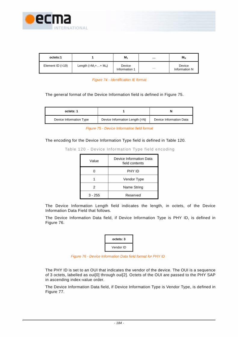
The general format of the Device Information field is defined in Figure 75.
The encoding for the Device Information Type field is defined in Table 120.
The Device Information Length field indicates the length, in octets, of the DeviceInformation Data Field that follows.
The Device Information Data field, if Device Information Type is PHY ID, is defined inFigure 76.
The PHY ID is set to an OUI that indicates the vendor of the device. The OUI is a sequenceof 3 octets, labelled as oui[0] through oui[2]. Octets of the OUI are passed to the PHY SAPin ascending index-value order.
The Device Information Data field, if Device Information Type is Vendor Type, is defined inFigure 77.
Table 120 - Device Informat ion Type f ie ld encoding
Value Device Information Data field contents
0 PHY ID
1 Vendor Type
2 Name String
3 - 255 Reserved
octets:1 1 M1 … MN
Element ID (=19) Length (=M1+…+ MN) Device Information 1 … Device
Information N
Figure 74 - Identification IE format
octets: 1 1 N
Device Information Type Device Information Length (=N) Device Information Data
Figure 75 - Device Information field format
octets: 3
Vendor ID
Figure 76 - Device Information Data field format for PHY ID
- 184 -

The PHY ID field is set to an OUI that indicates the entity that assigns the values used inthe Device Type ID field. The Device Type ID field indicates the type of device.
The Device Information Data field, if Device Information Type is Name String, contains thename of the device encoded in Unicode UTF-16LE format, and is defined in Figure 78.
16.8.11 Link feedback IEThe Link Feedback IE contains information on the recommended change to the data rateand transmit power level by a recipient device for one or more source devices. The LinkFeedback IE is defined in Figure 79.
The Link field is defined in Figure 80.
The DevAddr field is set to the DevAddr of the source device for which the feedback isprovided.
octets: 3 3
Vendor ID Device Type ID
Figure 77 - Device Information Data field format for Vendor Type
octets: 2 … 2
Name String Unicode Char 1 … Name String
Unicode Char N
Figure 78 - Device Information Data field format for Name String
octets: 1 1 3 3
Element ID (=16) Length (=3xN) Link 1 … Link N
Figure 79 - Link Feedback IE format
bits: b23-b20 b19-b16 b15-b0
Data Rate Transmit Power Level Change DevAddr
Figure 80 - Link field format
- 185 -
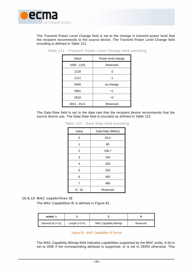
The Transmit Power Level Change field is set to the change in transmit power level thatthe recipient recommends to the source device. The Transmit Power Level Change fieldencoding is defined in Table 121.
The Data Rate field is set to the data rate that the recipient device recommends that thesource device use. The Data Rate field is encoded as defined in Table 122.
16.8.12 MAC capabil i t ies IEThe MAC Capabilities IE is defined in Figure 81.
The MAC Capability Bitmap field indicates capabilities supported by the MAC entity. A bit isset to ONE if the corresponding attribute is supported, or is set to ZERO otherwise. This
Table 121 - Transmit Power Level Change f ie ld encoding
Value Power level change
1000 - 1101 Reserved
1110 -2
1111 -1
0000 no change
0001 +1
0010 +2
0011 - 0111 Reserved
Table 122 - Data Rate f ie ld encoding
Value Data Rate (Mbit/s)
0 53,3
1 80
2 106,7
3 160
4 200
5 320
6 400
7 480
8 - 15 Reserved
octets: 1 1 2 X
Element ID (=12) Length (=2+X) MAC Capability Bitmap Reserved
Figure 81 - MAC Capabilities IE format
- 186 -

field is encoded as described in Table 123. Subsequent octets are reserved and may ormay not be present.
16.8.13 Master key identif ier (MKID) IEThe MKID IE is used to identify some or all of the master keys possessed by the device.The MKID IE is defined in Figure 82.
Each MKID field is set to the identifier of a master key possessed by the device.
16.8.14 Mult icast address binding (MAB) IEEach device maps multicast EUI-48s to McstAddrs in the 16-bit DevAddr address range.The MAB IE declares the binding between a multicast EUI-48 and the McstAddr that thedevice will use when transmitting frames destined for that multicast EUI-48.
Table 123 - MAC Capabi l i ty Bi tmap
Octet Bit Attribute Description
0
0 PCA Capable of transmitting and receiving frames using the PCA mechanism
1 Hard DRP Capable of being the owner and target of Hard DRP reservations
2 Soft DRP Capable of being the owner and target of Soft DRP reservations
3 Block ACK Capable of transmitting and acknowledging frames using the B-ACK mechanism
4 Explicit DRP negotiation Capable of negotiating a DRP reservation using command frames
5 Hibernation anchor Capable of acting as a hibernation anchor
6 Probe Capable of responding to Probe IEs received in command frames
7 Link feedback Capable of generating and interpreting a Link Feedback IE
1 0 Range measurement Capable of initiating and participating in range measurement calculations
1 - 7 Reserved Reserved
octets: 1 1 16 … 16
Element ID (=20) Length (=16×N) MKID 1 … MKID N
Figure 82 - MKID IE format
- 187 -

The format of the MAB IE is defined in Figure 83.
The format of the Multicast Address Binding Block field is defined in Figure 84.
The MEUI field is set to the multicast EUI-48 supplied by the MAC client at the MAC SAP.
The MDevAddr field is set to the multicast DevAddr bound to the MEUI field by the MACentity from the McstAddr address range.
16.8.15 PCA availabil i ty IEThe PCA Availability IE identifies the MASs in which a device will be available to receivePCA traffic and transmit the required response.
The PCA Availability IE is defined in Figure 85.
The Interpretation field contains information that specifies the meaning of each bit in thePCA Availability Bitmap field. The Interpretation field is defined in Figure 86.
The TIM IE Required bit is set to ONE if the device will only be available to receive PCAtraffic in the specified MASs after receiving a TIM IE that addresses it. The bit is set toZERO if the device will be available to receive PCA traffic in the specified MASs regardlessof TIM IE reception.
The PCA Availability Bitmap field is up to 256 bits long, one bit for each MAS in thesuperframe, where the least-significant bit of the field corresponds to the first MAS in thesuperframe and successive bits correspond to successive MASs. Each bit is set to ONE if
octets: 1 1 8 … 8
Element ID (=22) Length (=8×N) Multicast Address Binding Block 1
… Multicast Address Binding Block N
Figure 83 - MAB IE format
octets : 6 2
MEUI MDevAddr
Figure 84 - Multicast Address Binding Block format
octets: 1 1 1 N (0 to 32)
Element ID (=2) Length (=N+1) Interpretation PCA Availability Bitmap
Figure 85 - PCA Availability IE format
bits: b7-b1 b0
Reserved TIM IE Required
Figure 86 - Interpretation field format
- 188 -

the device is available to receive PCA traffic and transmit the required response in thecorresponding MAS, or is set to ZERO otherwise. If the PCA Availability Bitmap field issmaller than 32 octets, the bits in octets not included at the end of the bitmap are treatedas ZERO.
16.8.16 PHY capabil i t ies IEThe PHY Capabilities IE pertaining to the PHY is defined in Figure 87.
The PHY Capability Bitmap field indicates capabilities supported by the PHY, as defined inthe Physical Layer Clauses of this specification (Clauses 7 - 15). A bit is set to ONE if thecorresponding attribute is supported, or is set to ZERO otherwise. This field is encoded asdescribed in Table 124. Subsequent octets are reserved and may or may not be present.
octets: 1 1 3 X
Element ID (=13) Length (=3+X) PHY Capability Bitmap Reserved
Figure 87 - PHY Capabilities IE format
- 189 -

Table 124 - PHY Capabi l i ty Bi tmap
Octet Bit Attribute Description
0
0 Band group 1 TFI Capable of transmitting and receiving frames using TFI channels in band group 1
1 Band group 1 FFI Capable of transmitting and receiving frames using FFI channels in band group 1
2 Band group 2 TFI Capable of transmitting and receiving frames using TFI channels in band group 2
3 Band group 2 FFI Capable of transmitting and receiving frames using FFI channels in band group 2
4 Band group 3 TFI Capable of transmitting and receiving frames using TFI channels in band group 3
5 Band group 3 FFI Capable of transmitting and receiving frames using FFI channels in band group 3
6 Band group 4 TFI Capable of transmitting and receiving frames using TFI channels in band group 4
7 Band group 4 FFI Capable of transmitting and receiving frames using FFI channels in band group 4
1 0 Band group 5 TFI Capable of transmitting and receiving frames using TFI2 channel in band group 5
1 Band group 5 FFI Capable of transmitting and receiving frames using FFI channels in band group 5
2 Band group 6 TFI Capable of transmitting and receiving frames using TFI channels in band group 6
3 Band group 6 FFI Capable of transmitting and receiving frames using FFI channels in band group 6
4 - 6 Reserved Reserved
7 TFI2 Capable of transmitting and receiving frames using TFI2 channels in any band group for which TFI capability is indicated
2 0 53,3 Mb/s Capable of receiving frames using the 53,3 Mb/s PHY data rate
1 80 Mb/s Capable of receiving frames using the 80 Mb/s PHY data rate
2 106,7 Mb/s Capable of receiving frames using the 106,7 Mb/s PHY data rate
3 160 Mb/s Capable of receiving frames using the 160 Mb/s PHY data rate
4 200 Mb/s Capable of receiving frames using the 200 Mb/s PHY data rate
5 320 Mb/s Capable of receiving frames using the 320 Mb/s PHY data rate
6 400 Mb/s Capable of receiving frames using the 400 Mb/s PHY data rate
7 480 Mb/s Capable of receiving frames using the 480 Mb/s PHY data rate
- 190 -

16.8.17 Probe IEThe Probe IE is used to request information from a device. It is defined in Figure 88.
The Target DevAddr field is set to the DevAddr of the device from which IEs are requestedor the device that requests IEs.
Each Requested Element ID field is set to the element ID of a requested IE.
16.8.18 Regulatory Domain IEThe Regulatory Domain IE is used to announce the operational regulatory domain andother information potentially relevant to regulatory requirements. It is defined in Figure 89.
The Regulatory Domain Control field is defined in Figure 90.
The Location-aware bit is set to ONE if the transmitting device knows the device is locatedin the regulatory domain indicated in the Regulatory Domain Number field through externalmeans. It is set to ZERO otherwise.
The Regulatory Domain Number field is set to a number indicating the regulatory domain.The numbers for regulator domains can be found in the Regulatory Domain Register. Usethe link at http://www.ecma-international.org/publications/standards/Ecma-368.htm to viewthe Regulatory Domain Register.
The Mains Connection Status field indicates the minimum number of hops from the sendingdevice to a device that is connected to a mains power source. It is set to zero by a devicethat is connected to a mains power source. If a device is not connected to a mains powersource, it is set to one greater than the minimum value found in this field of a RegulatoryDomain IE received from any neighbour, but not more than mMaxMainsHopCount. If adevice is not connected to a mains power source and no Regulatory Domain IE is receivedfrom any neighbour, the field is set to mMaxMainsHopCount.
octets: 1 1 2 1 … 1
Element ID (=14) Length (=2+N) Target DevAddr Requested Element ID 1 … Requested
Element ID N
Figure 88 - Probe IE format for standard IEs
octets: 1 1 2
Element ID (=24) Length (=2) Regulatory Domain Control
Figure 89 - Regulatory Domain IE format
Bits : b15-b9 b8-b7 b6-b1 b0
Reserved Mains Connection Status Regulatory Domain Number Location-aware
Figure 90 - Regulatory Domain Control field format
- 191 -
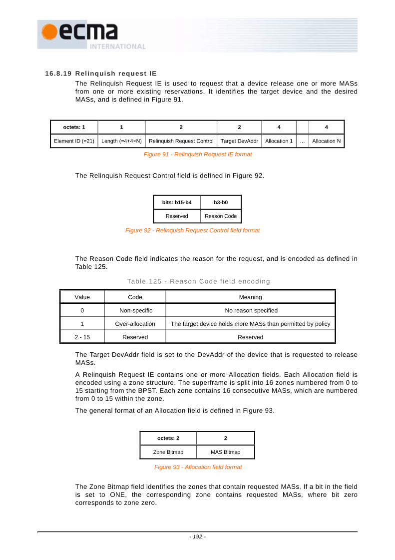
16.8.19 Relinquish request IEThe Relinquish Request IE is used to request that a device release one or more MASsfrom one or more existing reservations. It identifies the target device and the desiredMASs, and is defined in Figure 91.
The Relinquish Request Control field is defined in Figure 92.
The Reason Code field indicates the reason for the request, and is encoded as defined inTable 125.
The Target DevAddr field is set to the DevAddr of the device that is requested to releaseMASs.
A Relinquish Request IE contains one or more Allocation fields. Each Allocation field isencoded using a zone structure. The superframe is split into 16 zones numbered from 0 to15 starting from the BPST. Each zone contains 16 consecutive MASs, which are numberedfrom 0 to 15 within the zone.
The general format of an Allocation field is defined in Figure 93.
The Zone Bitmap field identifies the zones that contain requested MASs. If a bit in the fieldis set to ONE, the corresponding zone contains requested MASs, where bit zerocorresponds to zone zero.
Table 125 - Reason Code f ie ld encoding
Value Code Meaning
0 Non-specific No reason specified
1 Over-allocation The target device holds more MASs than permitted by policy
2 - 15 Reserved Reserved
octets: 1 1 2 2 4 4
Element ID (=21) Length (=4+4×N) Relinquish Request Control Target DevAddr Allocation 1 … Allocation N
Figure 91 - Relinquish Request IE format
bits: b15-b4 b3-b0
Reserved Reason Code
Figure 92 - Relinquish Request Control field format
octets: 2 2
Zone Bitmap MAS Bitmap
Figure 93 - Allocation field format
- 192 -

The MAS Bitmap specifies which MASs in the zones identified by the Zone Bitmap field arepart of the request. If a bit in the field is set to ONE, the corresponding MAS within eachzone identified by the Zone Bitmap is included in the request, where bit zero correspondsto MAS zero within the zone.
16.8.20 Tone-null ing (TN) IEThe TN IE is used to announce which PHY tones are not used (nulled) when transmittingframes from this device and to request neighbour devices to null specific tones in framesthey transmit. To null a tone, a device transmits with reduced energy on that tone. The TNIE is defined in Figure 94.
The TN Control field is defined in Figure 95.
The Co-located Radio Indication bit is set to ONE if the tone-nulling announcement istransmitted by a device with a co-located radio and the TN Map requests to null tonesbecause of that radio, and is set to ZERO otherwise. A co-located radio is another radio inthe same end product for which certain frequencies must be protected or avoided.
The Origin Indication bit is set to ONE if the transmitting device is the originator of theinformation in the TN IE, and is set to ZERO otherwise.
The Avoided Tone Indication bit is set to ONE if the transmitting device nulls the tonesidentified in the TN Map field in frames it transmits, and is set to ZERO otherwise.
The Protected Tone Request bit is set to ONE if the transmitting device is requesting itsneighbors to null the tones identified in the TN Map field in frames they transmit, and is setto ZERO otherwise.
The Avoided Adjacent Tones field contains the number of tones adjacent to each side ofeach notch in the TN map field that are nulled by the transmitting device.
The PHY portion of this specification identifies certain tones to have associated symmetrictones. The Avoided Symmetric Tones bit is set to ONE to indicate that the transmittingdevice will also null tones symmetric to those indicated in the Tone-nulling Map field.
The Avoided Adjacent Tones field and Avoided Symmetric Tones bit permit a device toindicate that it nulls tones in frames it transmits in addition to those tones that it requests tobe nulled by a neighbour.
octets: 1 1 2 2xN
Element ID (=23) Length (=2+2xN) TN Control TN Map
Figure 94 - Tone-nulling IE format
Bits : b15-b7 b6 b5-b4 b3 b2 B1 b0
Reserved Avoided Symmetric
Tones
Avoided Adjacent
Tones
Protected Tone Request
Avoided Tone Indication
Origin Indication
Co-located Radio
Indication
Figure 95 - Tone-nulling Control field format
- 193 -

The TN Map field consists of one or more TN Map Segment fields identifying disjointsubsets of tones in the operational band group. The TN Map Segment fields of a TN Mapfield are ordered successively from the lowest-numbered to the highest-numbered TNelements identified in the TN Map Segment field. The format of each TN Map Segmentfield is defined in Figure 96.
Each TN Map Segment field identifies a set of consecutively numbered TN elements. TNelements correspond to tones in the operational band group as defined and numbered inthe Physical Layer Specification.
The Tone Count field is set to the number of TN elements identified by the TN MapSegment field.
The Tone Offset field is set to the smallest TN element number identified by the TN MapSegment field.
The set of TN elements identified by the TN Map Segment field consists of the TNelements identified by the Tone Offset field and the following (Tone Count - 1) consecutivehigher-numbered TN elements.
16.8.21 Traff ic indication map (TIM) IEThe TIM IE is used to indicate that an active mode device has data buffered fortransmission via PCA. The TIM IE is defined in Figure 97.
Each DevAddr field is set to a valid target DevAddr for which PCA traffic is buffered.
17 MAC sublayer functional description
This Clause specifies MAC sublayer functionality. The rules for transmission and reception ofMAC frames, including setting and processing MAC header fields and information elements, arespecified in 17.1.
Channel time is divided into superframes, with each superframe composed of two major parts,the beacon period (BP) and the data period. Beacon transmission and reception in the BP andmerging of BPs are specified in 17.2
During the data period devices send and receive data using prioritized contention access (PCA)or in reservations established using the distributed reservation protocol (DRP). PCA permitsmultiple devices to contend for access to the medium based on traffic priority, and is specified in
Bits : b15 b14-b6 b5-b0
Reserved Tone Offset Tone Count
Figure 96 - TN Map Segment field format
octets:1 1 2 … 2
Element ID (=0) Length (=2×N) DevAddr 1 … DevAddr N
Figure 97 - TIM IE format
- 194 -

17.3. The DRP enables a device to gain scheduled access to the medium within a negotiatedreservation, and is specified in 17.4.
Device synchronization is specified in 17.5. The fragmentation and reassembly of MSDUs isspecified in 17.6. Aggregation of multiple MSDUs in a single frame is specified in 17.7.Acknowledgement mechanisms are specified in 17.8. Clauses 17.9 through 17.15 specify probecommands, dynamic channel selection, multi-rate support, transmit power control, powermanagement mechanisms, use of ASIEs and range measurement. Clause 8.16 specifies valuesfor all MAC sublayer parameters.
17.1 Frame processingThis Clause provides rules on preparing MAC frames for transmission and processing themon reception. The rules cover MAC header fields and information elements.
17.1.1 Frame addressesFrames are addressed using DevAddrs. There are four types of DevAddrs: Private,Generated, Multicast, and Broadcast. Table 126 defined the range for each type ofDevAddr.
A device shall associate a Generated DevAddr with its local MAC sublayer and use thatDevAddr in its beacon. A device shall select the a Generated DevAddr from the GeneratedDevAddr range at random with equal probability and should ensure that the generatedvalue is unique among all devices in its extended beacon group.
Except in Private reservations, in all frames transmitted, a device shall set the SrcAddrfield to its own DevAddr. In unicast frames, the DestAddr field shall be set to the DevAddrof the recipient. In multicast frames, the DestAddr field shall be set to an address from theMulticast DevAddr range, as specified in 17.1.10.14. In broadcast frames, the DestAddrfield shall be set to the Broadcast DevAddr.
A device shall not transmit frames addressed with a Private DevAddr at any time outside aPrivate reservation.
17.1.1.1 DevAddr confl ictsA device with a Generated DevAddr shall recognize that its DevAddr is in conflict if anyof the following conditions occurs:
• It receives a frame header in which the SrcAddr is the same as its own DevAddr; or
• It receives a beacon frame in which the BPOIE contains a DevAddr that is the same as itsown but does not correspond to a beacon slot in which the device transmitted a beacon inthe last superframe, and does not correspond to a beacon slot in which the devicetransmitted a beacon containing a Hibernation Mode IE with a hibernation duration thathas not yet expired.
Table 126 - DevAddr types and ranges
Type Range
Private 0x0000 - 0x00FF
Generated 0x0100 - 0xFEFF
Multicast (McstAddr)
0xFF00 - 0xFFFE
Broadcast (BcstAddr)
0xFFFF
- 195 -

A device that recognizes that its DevAddr is in conflict shall generate a new DevAddr toresolve the DevAddr conflict and use that DevAddr starting in its next transmittedbeacon.
17.1.2 Frame receptionUnless otherwise indicated, a frame is considered to be received by the device if it has avalid header check sequence (HCS) and frame check sequence (FCS) as defined in 16.2.7and indicates a protocol version that is supported by the device. The HCS is validated bythe PHY, which indicates whether or not a header error occurred.
A frame header is considered to be received by the device if it has a valid HCS andindicates a protocol version supported by the device, regardless of the FCS validation.
17.1.3 Frame transactionA frame transaction consists of an optional RTS/CTS frame exchange, a single frame, andthe associated acknowledgement frame if requested by the ACK policy.
Figure 98 shows some frame transaction examples.
NOTEFor the PHY, header errors are reported in the RXVECTOR parameter, as defined in Table 56.
Figure 98 - Frame transaction examples
RTS
Frame transactionFrames transmitted bysource device
Frames transmitted by
recipient device
CTS
Frame 3 (I-ACK)
Frame 5 (I-ACK)
I-ACK I-ACK
Frame transaction
RTS
Frame transactionFrames transmitted bysource device
Frames transmitted by
recipient device
CTS
Frame 3 (B-ACK)
B-ACK
Frame 4 (B-ACK)
Frame 5 (B-REQ)
Frametransaction Frame transaction
RTS
Frame transactionFrames transmitted bysource device
Frames transmitted by
recipient device
CTS
Frame 3 (N-ACK)
Frame 4 (N-ACK)
Frametransaction
Frame 5 (N-ACK)
Frametransaction
Frame 6 (N-ACK)
Frametransaction
I-ACK = Imm-ACKN-ACK = No-ACKB-REQ = B-ACK Request
- 196 -

17.1.4 Frame transferA source device shall transmit MSDUs associated with the same Delivery ID andaddressed to the same destination EUI-48 in the order in which they arrived at the localMAC SAP. The device shall treat each MSDU of length n as a sequence of octets, labelledMSDU[0] to MSDU[n-1], and shall place these octets in the payload field in ascendingindex-value order. The device shall transmit fragments of an MSDU or MCDU in order ofincreasing fragment number.
The MAC entity shall translate the EUI-48 provided by the MAC client along with an MSDUto the DevAddr of the target for use in the transmission of the MSDU over the medium.
When using the B-ACK mechanism, a source device may retransmit some previouslytransmitted frames, causing the sequence numbers and fragment numbers of theretransmitted frames to be out of order with respect to previously transmitted frames.
A source device may reorder MSDUs for transmission if their associated Delivery IDs ordestination EUI-48s are different.
A recipient device shall release MSDUs to the MAC client that were transmitted by thesame source device with the same Delivery ID in order of increasing sequence numbervalues.
A source device may fragment or aggregate MSDUs for transfer between peer MACentities, but the recipient device shall deliver whole individual MSDUs through the MACSAP to the MAC client.
17.1.5 Frame retry A frame retry is a retransmission of a previously transmitted frame from the same sourcedevice to the same recipient device. In a frame that is retransmitted, the source deviceshall set the Retry bit to ONE.
Unless otherwise stated, in this specification "transmission" means transmission of a newframe or retransmission of a previously transmitted frame.
A device may retransmit a frame as needed, taking into consideration such factors asdelay requirements, fairness policies, channel conditions, and medium availability. Adevice shall apply the medium access rules for new frame transmissions whenretransmitting frames, unless stated otherwise.
17.1.6 Inter-frame space ( IFS)Three types of IFS are used in this Standard: the minimum inter-frame space (MIFS), theshort inter-frame space (SIFS), and the arbitration inter-frame space (AIFS[i]). There arefour values of AIFS depending on the access category of the traffic. The actual values ofthe MIFS, SIFS, and AIFS are PHY-dependent. The derivation of the values of AIFS[i] isdescribed in 17.3.4.1.
A device shall not start transmission of a frame on the medium with non-zero lengthpayload earlier than MIFS, or with zero length payload earlier than SIFS, after the end of aframe it transmitted previously on the medium. A device shall not start transmission of aframe on the medium earlier than SIFS duration after the end of a previously receivedframe on the medium.
17.1.6.1 MIFSBurst frame transmissions are those frames transmitted from the same device where thetiming of each frame in the burst after the first is related to the preceding frame throughuse of the PHY burst mode. In this case a MIFS duration will occur between frames inthe burst, as defined in Figure 99. All frames in a burst except the last frame shall besent with the ACK Policy field set to No-ACK or B-ACK. The last frame in a burst may besent with any ACK Policy.
- 197 -
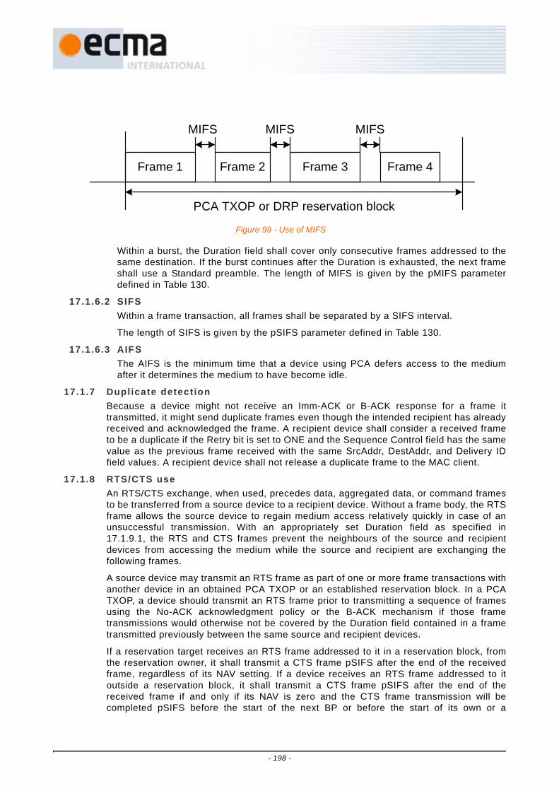
Within a burst, the Duration field shall cover only consecutive frames addressed to thesame destination. If the burst continues after the Duration is exhausted, the next frameshall use a Standard preamble. The length of MIFS is given by the pMIFS parameterdefined in Table 130.
17.1.6.2 SIFSWithin a frame transaction, all frames shall be separated by a SIFS interval.
The length of SIFS is given by the pSIFS parameter defined in Table 130.
17.1.6.3 AIFSThe AIFS is the minimum time that a device using PCA defers access to the mediumafter it determines the medium to have become idle.
17.1.7 Duplicate detectionBecause a device might not receive an Imm-ACK or B-ACK response for a frame ittransmitted, it might send duplicate frames even though the intended recipient has alreadyreceived and acknowledged the frame. A recipient device shall consider a received frameto be a duplicate if the Retry bit is set to ONE and the Sequence Control field has the samevalue as the previous frame received with the same SrcAddr, DestAddr, and Delivery IDfield values. A recipient device shall not release a duplicate frame to the MAC client.
17.1.8 RTS/CTS useAn RTS/CTS exchange, when used, precedes data, aggregated data, or command framesto be transferred from a source device to a recipient device. Without a frame body, the RTSframe allows the source device to regain medium access relatively quickly in case of anunsuccessful transmission. With an appropriately set Duration field as specified in17.1.9.1, the RTS and CTS frames prevent the neighbours of the source and recipientdevices from accessing the medium while the source and recipient are exchanging thefollowing frames.
A source device may transmit an RTS frame as part of one or more frame transactions withanother device in an obtained PCA TXOP or an established reservation block. In a PCATXOP, a device should transmit an RTS frame prior to transmitting a sequence of framesusing the No-ACK acknowledgment policy or the B-ACK mechanism if those frametransmissions would otherwise not be covered by the Duration field contained in a frametransmitted previously between the same source and recipient devices.
If a reservation target receives an RTS frame addressed to it in a reservation block, fromthe reservation owner, it shall transmit a CTS frame pSIFS after the end of the receivedframe, regardless of its NAV setting. If a device receives an RTS frame addressed to itoutside a reservation block, it shall transmit a CTS frame pSIFS after the end of thereceived frame if and only if its NAV is zero and the CTS frame transmission will becompleted pSIFS before the start of the next BP or before the start of its own or a
Frame 1 Frame 2 Frame 3 Frame 4
MIFS MIFS MIFS
PCA TXOP or DRP reservation block
Figure 99 - Use of MIFS
- 198 -

neighbour’s established reservation block. However, a device should not transmit a CTSframe if the Duration indicated in the RTS frame extends beyond a point in time pSIFSprior to the start of the next BP or the start of its own or a neighbour’s establishedreservation block.
On receiving an expected CTS response, the source device shall transmit the frame, or thefirst of the frames, for which it transmitted the preceding RTS frame pSIFS after the end ofthe received CTS frame. If the source device does not receive the expected CTS framepSIFS plus the CTS frame transmission time after the end of the RTS frame transmission,and it transmitted the RTS frame in a PCA TXOP, it shall invoke a backoff as specified in17.3. If it transmitted the RTS frame in one of its reservation blocks, it shall not retransmitthe RTS frame or transmit another frame earlier than pSIFS after the end of the expectedCTS frame.
17.1.9 MAC header f ields17.1.9.1 Duration
A device shall set the Duration field in beacon frames to one of the following:
• The time remaining in the BP measured from the end of the PLCP header of the beaconframe, as determined by the largest BP length announced by neighbours of the device inthe previous superframe;
• The transmission time of the frame body of the beacon frame; or
• Zero.
A device shall set the Duration field in RTS, command, data, or aggregated data framesto the sum of:
• The transmission time of the frame body of the current frame;
• The transmission time of the expected response frame for the current frame (CTS, Imm-ACK, or B-ACK frame), if any;
• The transmission time of subsequent frames, if any, to be sent to the same recipient up toand including (a) the next RTS frame or frame with ACK Policy set to Imm-ACK or B-ACKRequest or (b) the last frame in the PCA TXOP or reservation block, whichever is earlier;or, alternatively, the transmission time of the next frame in the PCA TXOP or reservationblock to be sent to the same recipient, if any; and
• All the IFSs separating the frames included in the Duration calculation.
A device shall not set the Duration field in an RTS, command, data, or aggregated dataframe to a value that extends beyond the end of its current TXOP or reservation block.
The calculated value for Duration has a required accuracy of +/- one microsecond perframe included in the calculation.
A device may estimate the transmission time of a B-ACK frame body based on theexpected length and data rate, or may assume a zero-length frame body.
A device shall set the Duration field in CTS, Imm-ACK and B-ACK frames to the larger ofzero or a value equal to the duration value contained in the previous frame minus pSIFS,minus the transmission time of the frame body of the received frame to which the CTS,Imm-ACK or B-ACK is responding, minus the transmission time up to the end of thePLCP header of this CTS, Imm-ACK or B-ACK frame.
The following exceptions to previous rules are allowed:
• For frames with ACK Policy set to B-ACK Request, a device may set the Duration to thesum of the transmission time of the frame body of the B-ACK Request frame plus a SIFSplus the estimated transmission time of the expected B-ACK response frame.
- 199 -

• A device may set the Duration for any frame sent in a Hard or Private reservation blockother than UDA or UDR frames to zero.
A device shall set the Duration field in UDA and UDR frames to a time interval extendingfrom the end of the PLCP header of the current frame to the time when the remainingDRP reservation block is to be released.
Examples of Duration field values are defined in Figure 100.
- 200 -

Figure 100 - Duration Examples
RTS
DurationFrames
transmitted bysource device
Frames transmitted by
recipient device
CTS
Frame 3 (I-ACK)
Frame 5 (I-ACK)
I-ACK I-ACK
Duration
Duration
Duration
Duration
ZeroDuration
I-ACK = Imm-ACKN-ACK = No-ACKB-REQ = B-ACK Request
RTS
DurationFrames
transmitted bysource device
Frames transmitted by
recipient device
CTS
Frame 3 (B-ACK)
B-ACK
Frame 4 (B-ACK)
Frame 5 (B-REQ)
Duration
DurationDuration
Duration
...
RTS
DurationFrames
transmitted bysource device
Frames transmitted by
recipient device
CTS
Frame 3 (N-ACK)
Frame 4 (N-ACK)
Frame 5 (N-ACK)
Frame 6 (N-ACK)
Duration
DurationDuration
Duration
DurationFrames
transmitted bysource device
Frames transmitted by
recipient device
UDR
UDA
Duration
UDR UDR UDR
Duration
Duration ZeroDuration
DRP reservation
releasedat this time
- 201 -

17.1.9.2 More framesIf a device sets the More Frames bit to ZERO in a frame sent with Access Method set toONE, it shall not transmit additional frames to the same recipient(s) within thereservation block.
If a device sets the More Frames bit to ZERO in a frame sent with Access Method set toZERO, it shall not transmit additional frames using PCA to the same recipient(s) withinthe current superframe unless the recipient did not include a PCA Availability IE in itsbeacon or included a PCA Availability IE in its beacon with the TIM IE Required bit set toZERO.
17.1.9.3 Sequence numberThe Sequence Number field value is used for duplicate detection for frames sent usingthe Imm-ACK acknowledgement policy. It is used for both duplicate detection andreordering for frames sent using the B-ACK mechanism.
A device shall assign each MSDU or MCDU transmitted a sequence number from amodulo 2 048 counter.
A device shall assign the same sequence number to each fragment of an MSDU orMCDU.
A single sequence number applies to all MSDUs contained in an aggregated data frame.A device shall increment the sequence number counter by one for each transmittedaggregated data frame.
A device shall use a dedicated counter for MCDUs.
A device shall use a dedicated counter for each sequence of MSDUs addressed to thesame DestAddr with the same Delivery ID using B-ACK acknowledgement policy.
A device may use one counter for all other MSDUs, or may use a dedicated counter forMSDUs with the same Delivery ID field value addressed to the same DestAddr.
In each beacon frame transmitted in a superframe, a device shall set the SequenceNumber field from a dedicated counter that increments once per superframe, modulo2 048, or shall set it to zero.
17.1.10 Information elementsIEs are contained in beacon and command frames. They convey certain control andmanagement information. IEs may be explicitly requested using Probe command frames.
The remainder of this Clause describes when each IE is generated.
17.1.10.1 Application-specif ic IE (ASIE)A device may include an ASIE in its beacon for each of its applications which have madethe request, as described in 17.14. The scope of the ASIE is dependent on theapplication that requested the inclusion of the ASIE.
17.1.10.2 Application-specif ic Probe IEA device may send an Application-specific Probe IE in order to request a specific ASIE.The scope and required response is dependent on the application that defines the ASIE.
17.1.10.3 Beacon period occupancy IE (BPOIE)A device shall always include a BPOIE in its beacon. In the BPOIE the device shallindicate beacons received from neighbours in the previous superframe, as well asinformation retained based on hibernation mode rules. It shall also indicate PHY mediumactivity that resulted in HCS errors, beacon frame headers received and alien beaconsreceived within its BP in the previous superframe. It may also indicate non-beaconframes received within its BP. If the device receives a beacon within 2×mGuardTime of
- 202 -

the start of a signaling slot with the Signaling Slot bit set to ONE, it shall also indicatethat beacon as if it were aligned to its BPST. The device shall encode all indicatedinformation in the BPOIE as described in 16.8.3, except a device is not required toindicate any activity in its own beacon slot.
17.1.10.4 BP switch IEA device should include a BP Switch IE in its beacon prior to changing its BPST, asspecified in 17.2.6.
17.1.10.5 Channel change IEA device should include a Channel Change IE in its beacon prior to changing to adifferent channel. A device that includes a Channel Change IE should change channelsas indicated in the IE.
17.1.10.6 Distr ibuted reservation protocol (DRP) IEA device shall include DRP IEs in its beacon for all reservations in which it participatesas a reservation owner or target, as described in 17.4.
If a device receives a frame containing a DRP IE with the Reservation Type field set to areserved value, it shall not respond to the DRP IE, but shall treat the DRP IE as if theReservation Type field were set to Private.
A device shall interpret a DRP IE transmitted or received in the current superframe togrant or deny access to the medium in the next superframe, depending on the accessrules specific to the indicated Reservation Type in the IE.
17.1.10.7 DRP availabi l i ty IEA device shall include a DRP Availability IE in its beacon as required to support DRPreservation negotiation, as described in 17.4. A DRP Availability IE received in thecurrent superframe reflects availability prior to that superframe.
17.1.10.8 Hibernation anchor IEA device that indicates it is capable of acting as a hibernation anchor should include aHibernation Anchor IE in its beacon to provide information on neighbours that arecurrently in hibernation mode as described in 17.13.5.
17.1.10.9 Hibernation mode IEA device shall include a Hibernation Mode IE in its beacon before entering hibernationmode, as specified in 17.13.4. A device that receives a Hibernation Mode IE shall reportthe beacon slot of the transmitter as occupied and non-movable in the BPOIE includedin its beacons during the reported hibernation duration.
17.1.10.10 Identif ication IEA device may include an Identification IE in its beacon to provide its own identifyinginformation to neighbours.
17.1.10.11 Link feedback IEA device may include a Link Feedback IE in its beacon to provide feedback on a link witha specific neighbour.
17.1.10.12 MAC capabil i t ies IEA device may include a MAC Capabilities IE in its beacon.
17.1.10.13 Master key identif ier (MKID) IEA device may include a MKID IE in its beacon to identify some or all of the master keys itpossesses.
- 203 -

17.1.10.14 Mult icast address binding (MAB) IEA device may include a MAB IE for any active multicast bindings between multicast EUI-48s and McstAddrs. A device should include a MAB IE in its beacon for at leastmMaxLostBeacons+1 superframes on activating a multicast address binding fortransmission and upon detection of a change in the beacon group.
A device shall not transmit frames with a McstAddr destination address in the currentsuperframe unless a binding to a multicast EUI-48 has been declared by inclusion of acorresponding MAB IE in its beacon in the prior and current superframes.
On receipt of a MAB IE the MAC sublayer shall establish an association between thesource of the MAB IE and the multicast DevAddr and multicast EUI-48 in each MulticastAddress Binding Block, to be used in address translations for the bound multicastaddresses.
The MAC entity shall deliver received MSDUs addressed to an activated multicastDevAddr to the MAC client on the multicast EUI-48 bound to that multicast DevAddr bythe source device of the MSDU.
17.1.10.15 PCA availabi l i ty IEA device may include a PCA Availability IE in its beacon as needed to facilitate PCA inthe presence of reservations or power constraints. Information in a PCA Availability IEreceived in the current superframe indicates availability of the device in that superframe.
17.1.10.16 PHY capabil i t ies IEA device may include a PHY Capabilities IE in its beacon.
17.1.10.17 Probe IEA device may include a Probe IE in its beacon to request certain IEs from anotherdevice. If a device receives a beacon containing a Probe IE in the current superframe,and is required to respond according to 17.9, it shall respond in the next superframe.
17.1.10.18 Regulatory Domain IEA device that has information about the operational regulatory domain should include aRegulatory Domain IE in its beacon at least once every mDAAAnnounceIntervalsuperframes, with the Location-aware bit set to ONE and the Regulatory DomainNumber field set as defined in 16.8.18. A device that does not have information aboutthe operational regulatory domain shall include a Regulatory Domain IE with theLocation-aware bit set to ZERO in its beacon at least once everymDAAAnnounceInterval superframes if in the last mDAAIEPersistence superframes itreceived a beacon from a neighbour containing a Regulatory Domain IE with theLocation-aware bit set to ONE. The device shall set the Regulatory Domain Number fieldto the most recent value received in that field within the last mDAAIEPersistencesuperframes from a neighbour with the Location-aware bit set to ONE.
A device that is operating in a regulatory domain that requires actions based onconnection to a mains power source shall act as follows: If the device is in active modeand is connected to a mains power source it shall include a Regulatory Domain IE in itsbeacon at least once every mDAAAnnounceInterval superframes, with the Mains HopCount field set to zero. If the device is in active mode and is not connected to a mainspower source or its power source is unknown it shall include a Regulatory Domain IE inits beacon at least once every mDAAAnnounceInterval superframes if in the lastmDAAIEPersistence superframes it received a Regulatory Domain IE. The device shallset the Mains Hop Count field to one greater than the lowest value in the Mains HopCount field in the latest Regulatory Domain IE received from each neighbour, but notgreater than mMaxMainsHopCount.
- 204 -

If a device determines that any information in its Regulatory Domain IE has changed, itshould include the IE in its beacon in the next mMaxLostBeacons+1 superframes.
17.1.10.19 Relinquish request IEA device may include a Relinquish Request IE in its beacon to request that a neighbourrelease one or more MASs from reservations.
If a reservation target receives a request to relinquish certain MASs included in areservation, it shall include in its beacon a DRP Availability IE and a Relinquish RequestIE identifying those MASs with the Target DevAddr field set to the DevAddr of thereservation owner. The device shall include the IEs in its beacon formMaxLostBeacons+1 superframes following the superframe in which it received therelinquish request, unless the reservation owner changes the reservation such that itdoes not contain the requested MASs.
17.1.10.20 Tone-null ing IEAn active mode device that nulls one or more tones during its transmissions shallinclude a Tone-nulling IE that identifies the nulled tones and has the Avoided ToneIndication bit set to ONE in its beacon at least once every mDAAAnnounceIntervalsuperframes. An active mode device may request neighbour devices to null tones inframes they transmit by including a Tone-nulling IE with the Protected Tone Request bitset to ONE in its beacon at least once every mDAAAnnounceInterval superframes.
The required response to reception of a Tone-nulling IE is dependent on the operationalregulatory domain and other factors, and is out of scope of this standard.
A device should minimize the number of Tone-nulling IEs sent in a beacon by combiningtone-nulling information into a single IE.
If a device determines that any information in its Tone-nulling IEs has changed, it shouldinclude Tone-nulling IEs in its beacon in the next mMaxLostBeacons + 1 superframes.
A device that did not receive a Tone-nulling IE from a neighbour in the lastmDAAIEPersistence superframes shall discard the Tone-nulling information previouslyreceived from that neighbour.
A device that enters hibernation mode for a period less than mDAAAnnounceIntervalsuperframes shall include IEs in its beacon as required for an active mode device. Adevice that enters hibernation mode for a period equal to or longer thanmDAAAnnounceInterval superframes shall include required IEs in its last beacon prior tohibernating and its first beacon after hibernating.
17.1.10.21 Traff ic indication map (TIM) IEA device shall include a TIM IE in its beacon in the current superframe if it has framesqueued for transmission to one or more recipients that require a TIM IE. A device shallconsider a recipient to require a TIM IE if the most recent beacon received from therecipient, within the last mMaxLostBeacons+1 superframes, contained a PCAAvailability IE with the TIM IE Required bit set to ONE. The TIM IE shall include theDevAddrs of all such recipients.
17.2 Beacon periodEach superframe starts with a BP, which has a maximum length of mMaxBPLength beaconslots. The length of each beacon slot is mBeaconSlotLength. Beacon slots in the BP arenumbered in sequence, starting at zero. The first mSignalSlotCount beacon slots of a BP arereferred to as signaling slots and are used to extend the BP length of neighbours.
An active mode device shall transmit and receive beacons as described in this clause. Whentransmitting in a beacon slot, a device shall start transmission of the frame on the medium atthe beginning of that beacon slot.
- 205 -

A device shall transmit beacons at pBeaconTransmitRate. The transmission time of beaconframes shall not exceed mMaxBeaconLength. This allows for a guard time of at leastmGuardTime and pSIFS between the end of a beacon and the start of the next beacon slot.
Figure 101 illustrates an example of a BP observed by a device in a given superframe.
17.2.1 Beacon slot stateA device shall consider a beacon slot unavailable if in any of the latestmMaxLostBeacons+1 superframes:
• The beacon slot was considered to be occupied (according to Table 117); or
• The beacon slot was encoded as occupied (according to Table 117) in the BPOIE of anybeacon received by the device.
A device shall consider a beacon slot available in all other cases.
17.2.2 BP lengthA device shall consider a beacon slot to be monitored if in any of the latestmMaxLostBeacons+1 superframes:
• The device received a beacon frame in that beacon slot that is aligned to its BPST;
• The device received a beacon frame with an invalid FCS within 2×mGuardTime of thatbeacon slot boundary; or
• The beacon slot was encoded as occupied (according to Table 117) with a DevAddr notequal to BcstAddr in the BPOIE of any beacon received by the device.
A device shall announce its BP length in its beacon as a count of beacon slots starting fromthe BPST. The announced BP length shall include a) The device's own beacon slot in thecurrent superframe, b) All monitored beacon slots in the BP of the prior superframe, and c)The beacon slot indicated in any beacon received in a signaling slot in the priorsuperframe.
Figure 101 - Example BP structure
DEV
5
DEV
9
DEV
3D
EV 1
DEV
8 ...
DEV
8
Superframe
Beacon Slots
Data period
Signaling slots
Highest-numbered unavailablebeacon slot seen by DEV 8
Largest BP Length announced
mMaxBPLength/2
0 1 2 3 4 5
mMaxBPLength
- 206 -

The announced BP length shall not include more than mBPExtension beacon slots afterthe latest of a, b, and c above, unless otherwise indicated in 17.2.6. The announced BPlength shall not exceed mMaxBPLength. Power-sensitive devices generally should notinclude any beacon slots after the last monitored beacon slot in their announced BP length.
The BP length reported by a device varies, as new devices become members of itsextended beacon group, and as the device or other devices in its extended beacon groupchoose a new beacon slot for beacon slot collision resolution or BP contraction.
17.2.3 Beacon transmission and reception17.2.3.1 Beacon transmission
Before a device transmits any frames, it shall scan for beacons for at least onesuperframe, or at least two superframes if no beacon frame is received. If the devicereceives no frame headers during the scan, it shall create a new BP and send a beaconin the first beacon slot after the signaling slots. If the device receives one or more frameheaders, but no beacon frames with a valid FCS during the scan, the device should scanfor an additional superframe.
If the device receives one or more beacons during the scan, it shall not create a new BP.Instead, prior to communicating with another device, the device shall transmit a beaconin a beacon slot selected from up to mBPExtension beacon slots located after thehighest-numbered unavailable beacon slot in the last superframe and withinmMaxBPLength after the BPST.
With the exception of transmitting its own beacon as described in 17.2.3, a device shallnot transmit frames in the current superframe during the BP length indicated in the mostrecent beacon received from of any neighbour in the previous mMaxLostBeacons+1superframes. A device shall not change beacon slots to a slot earlier than the highest-numbered unavailable beacon slot in the last superframe except as specified in 17.2.5.
17.2.3.2 NeighboursA device shall consider another device to be a neighbour if it has received a beaconfrom that device within the last mMaxLostBeacons+1 superframes, and the latestbeacon from the device indicated a BPST aligned with its own. If a device has notreceived a beacon from another device for the last mMaxLostBeacons+1 superframes, itshall not consider the device a neighbour.
A device shall not consider a received beacon with the Signaling Slot bit set to ONE asreceived from a neighbour.
17.2.3.3 Beacon slot coll isionIf a device detects a beacon slot collision as described in 17.2.4, it shall select adifferent beacon slot for its subsequent beacon transmissions from up to mBPExtensionbeacon slots located after the highest-numbered unavailable beacon slot in the lastsuperframe and within mMaxBPLength after the BPST.
17.2.3.4 Use of signaling slotsIf the beacon slot in which a device will transmit its beacon in the current superframe islocated beyond the BP length indicated in any beacon the device received from aneighbour in the previous superframe, the device shall also transmit the same beacon,except with the Signaling Slot bit set to ONE, in a randomly selected signaling slot,except as follows:
• A device should follow 17.2.6.4 if applicable.
• If a device transmits a beacon in a signaling slot for mMaxLostBeacons+1 consecutivesuperframes, it shall not transmit a beacon in a signaling slot in the nextmMaxLostBeacons+1 superframes, and it should not transmit a signaling slot beacon for
- 207 -

an additional aperiodic interval that does not exceed mMaxSignalingSlotBackoffsuperframes.
Subject to the preceding exceptions, a device also may send a beacon in a signaling slotin response to abnormal conditions, such as failure to receive a beacon from aneighbour that previously did not include the device's beacon slot in its BP Length, orfailure of a neighbour to report reception of the device's beacon in its BPOIE.
A device may consider a beacon received in a signaling slot as if it were not a receivedbeacon, except to report reception as required in 17.1.10.3 and to process the BeaconSlot Number field as required in 17.2.2 and 17.2.4.
17.2.3.5 Required reception intervalAn active mode device shall listen for neighbours’ beacons in the first N beacon slots ineach superframe, where N is the greater of its BP Length values for the current andprevious superframes, as defined in 17.2.2. At a minimum, the device shall listen forintervals such that it would receive a frame with a reception time within mGuardTime ofthe start of any of the N beacon slots.
If a device received a beacon with invalid FCS, or detected a medium activity that didnot result in reception of a frame with valid HCS in a signaling slot in the previoussuperframe, no BP length adjustment is required, but it shall listen for beacons for anadditional mBPExtension beacon slots after its BP length indicated in the currentsuperframe, but not more than mMaxBPLength beacon slots.
17.2.3.6 Skipping beacon transmissionAn active mode device shall transmit a beacon in each superframe, except as follows: Inorder to detect beacon slot collisions with neighbours, a device shall skip beacontransmission aperiodically, and listen for a potential neighbour in its beacon slot. Adevice shall skip beacon transmission, but not any associated signaling slot beacon, atleast every mMaxNeighborDetectionInterval. When a device skips beacon transmission,it shall act as if the skipped beacon were transmitted.
17.2.4 Beacon slot coll ision detectionA device shall consider itself involved in a beacon slot collision with another device in itsextended beacon group if one of the following events occurs:
• Its beacon slot is reported as occupied in the BPOIE in any beacon it receives in the currentsuperframe, but the corresponding DevAddr is neither BcstAddr nor its own DevAddr used inthe previous superframe.
• After skipping beacon transmission in the previous superframe, its beacon slot is reported asoccupied in the BPOIE in any beacon it receives in the current superframe, and thecorresponding DevAddr is not BcstAddr.
• When skipping beacon transmission in the current superframe, it receives a MAC header oftype beacon frame in its beacon slot
• It receives a signaling slot beacon aligned with one of its own signaling slots, with theBeacon Slot Number field set to its own beacon slot.
Certain events indicate a potential beacon slot collision. A device should consider thepossibility of a beacon slot collision and take appropriate action if one or more of thefollowing anomalous events occurs, or occurs consistently over multiple superframes:
• The device's beacon slot was reported as occupied and the corresponding DevAddr wasBcstAddr in the BPOIE of a beacon it received in the current superframe, and it sent abeacon in its beacon slot in the previous superframe.
- 208 -
• After skipping beacon transmission in the previous superframe, its beacon slot is reported asoccupied in the BPOIE in any beacon it receives in the current superframe and thecorresponding DevAddr is BcstAddr.
• When skipping beacon transmission in the current superframe, it receives a PHY indicationof medium activity in its beacon slot that does not result in correct reception of a frameheader.
In reaction to events that indicate a potential beacon slot collision, a device should:
• consider itself involved in a beacon slot collision and change slots as required in 17.2.3.3;
• skip beacon transmission; or
• send a beacon in a signaling slot, subject to requirements in 17.2.3.4.
At a minimum, a device shall execute at least one of these recommended reactions in thenext superframe if in mMaxBeaconSlotCollisionDetectionLatency consecutive superframesone or more of the anomalous events described above occurs, and the device has notexecuted a recommended reaction in those mMaxBeaconSlotCollisionDetectionLatencysuperframes.
Other events can also indicate a potential beacon slot collision. For example, if a device'sbeacon slot is frequently reported as unoccupied in the BPOIE of a beacon it receives, itcould indicate a collision, and the device may take action as described above.
17.2.5 BP contractionA device shall consider its beacon to be movable if in the previous superframe it found atleast one available beacon slot between the signaling slots and the beacon slot it indicatesin its beacon in the current superframe. However, for purposes of BP contraction, a devicemay consider an unoccupied beacon slot to be occupied for up to mMaxMovableLatencysuperframes, if it detects conditions that indicate contraction into that beacon slot mightlead to a beacon slot collision, such as a previous beacon slot collision or indication ofpoor link conditions in that beacon slot.
A device that includes a Hibernation Mode IE in its beacon shall consider its beacon to benon-movable during the announced hibernation period.
A device not involved in a beacon slot collision or a BP merge shall shift its beacon into theearliest available beacon slot following the signaling beacon slots in the BP of the nextsuperframe, if in each of the latest mMaxLostBeacons+1 superframes:
• The device’s beacon was movable; and
• the device did not receive a beacon from a neighbour that indicated a beacon slot after itsown and had the Movable bit set to ONE; and
• the device did not receive a beacon from a neighbour that contained a BPOIE that encoded abeacon slot after its own as Movable (per Table 127).
However, if in the last mMaxLostBeacons+1 superframes the device received a beaconfrom a neighbour that indicated a BP Length that did not include the device's beacon slot,and that beacon had the Movable bit set to ONE, the device should not change to anearlier beacon slot in the next superframe.
Figure 102 shows some examples of BP contraction.
- 209 -

17.2.6 Merger of mult iple BPsDue to changes in the propagation environment, mobility, or other effects, devices usingtwo or more unaligned BPSTs may come into range. This causes overlapping superframes.A received beacon with valid HCS and FCS that indicates a BPST that is not aligned with adevice's own BPST is referred to as an alien beacon. The BP defined by the BPST and BPlength in an alien beacon is referred to as an alien BP.
Synchronization problems could cause the beacon of a fast device to appear to be an alienbeacon. A device shall consider a BPST to be aligned with its own if that BPST differs fromits own by less than 2×mGuardTime. A device shall consider an alien BP to overlap its ownif its BPST falls within the alien BP or if the alien BPST falls within its own BP. A deviceshall not consider a beacon that has the Signaling Slot bit set to ONE to be an alienbeacon.
If a device does not receive an alien beacon for up to mMaxLostBeacons superframes afterreceiving one in a previous superframe, it shall use information contained in the most-recently received beacon as if the alien beacon were received at the same offset within thecurrent superframe.
17.2.6.1 Overlapping BPsIf the BPST of a device falls within an alien BP, the device shall relocate its beacon tothe alien BP according to the following rules:
1. The device shall change its BPST to the BPST of the alien BP.
2. The device shall adjust its beacon slot number such that its new beacon slot numberis its old beacon slot number plus one, plus the number of the highest occupiedbeacon slot indicated in any beacon received in the alien BP, minusmSignalSlotCount. Alternatively, it shall follow normal BP join rules as specified in17.2.3.1 to relocate its beacon to the alien BP.
3. The device shall not send further beacons in its previous BP.
17.2.6.2 Non-overlapping BPsIf a device detects an alien BP that does not overlap in time with its own BP, it shallmerge BPs according to the following rules.
1. The device shall include in its beacon a DRP IE with Reservation Type set to AlienBP for the alien BP. Since the MAS boundaries may not be aligned, the device mayneed to include an additional MAS in the reservation to completely cover the alienBP. If the device received multiple beacons from the alien BP, it shall include allMASs used by the largest reported BP length in the reservation. If the MASsoccupied by the alien BP change over time, the device shall update the DRP IEaccordingly.
Figure 102 - Illustration for BP contraction by example devices
...
Not MovablemMaxBPLength mMaxBPLength
...
Movable
DEV
2D
EV 5
DEV
9
DEV
3D
EV 1
DEV
8 ... ...
DEV
2D
EV 5
DEV
9
DEV
3D
EV 1
DEV
8
DEV
6D
EV 4
- 210 -

2. The device shall start the relocation process to the alien BP, according to 17.2.6.3,within mBPMergeWaitTime if the alien BPST falls within the first half of thesuperframe, or within 1.5×mBPMergeWaitTime if the alien BPST falls within thesecond half of the superframe, but shall not start the relocation process if a beaconreceived in that alien BP includes a BP Switch IE.
A device that transmits or receives a beacon in its own BP that contains a DRP IE withReservation Type set to Alien BP shall observe the following rules:
1. The device should not change beacon slots except as required by merge rules in17.2.6, unless a collision is detected.
2. If the device transmits the beacon that contains the Alien BP reservation, it shalllisten for beacons during the MASs indicated in the reservation. If the devicereceives the beacon that contains the Alien BP reservation, it should listen forbeacons during the MASs indicated in the reservation.
17.2.6.3 Beacon relocationIf a device starts or has started the beacon relocation process and receives an alienbeacon, it shall follow these rules:
A. If the device did not include a BP Switch IE in its last beacon, it shall include a BPSwitch IE in its beacon in the following superframe with the fields set as follows:
A1. The device shall set the BP Move Countdown field to mInitialMoveCountdown.
A2. The device shall set the BPST Offset field to the positive difference inmicroseconds between the alien BPST and the device's BPST. That is, the fieldcontains the number of microseconds that the device must delay its own BPSTto align with the alien BPST. If multiple alien beacons are received, the deviceshall set the BPST Offset field to the largest calculated value.
A3. The device shall set the Beacon Slot Offset field to:
a. One plus the number of the highest occupied beacon slot indicated by anybeacon received in the alien BP, based on the Beacon Slot Number field andBPOIE, minus mSignalSlotCount; or
b. Zero to indicate the device will join the alien BP using normal join rules asspecified in 17.2.3.
B. If the device included a BP Switch IE in its last beacon, it shall modify the BP SwitchIE in the following superframe as follows:
B1. If the elapsed time between the device's BPST and the following alien BPST islarger than the device's BPST Offset field + 2×mGuardTime, the device shallset the BP Move Countdown field, the BPST Offset field, and the Beacon SlotOffset field as described in A1, A2 and A3 above respectively.
B2. If the elapsed time between the device's BPST and the following alien BPST islarger than the device's BPST Offset field - 2×mGuardTime and smaller thanthe device's BPST Offset field + 2×mGuardTime, the device shall set the BPSTOffset field as described in A2. It shall set the Beacon Slot Offset field asdescribed in A3 if the value in the field would be increased, or leave itunchanged otherwise. It shall set the BP Move Countdown field to one lessthan the value used in its last beacon if the Beacon Slot Offset field isunchanged, or set it as described in A1 if the Beacon Slot Offset field ischanged.
If a device receives a neighbour’s beacon that contains a BP Switch IE, it shall followthese rules:
- 211 -

C. If the device did not include a BP Switch IE in its last beacon, it shall include a BPSwitch IE in its beacon in the following superframe with the fields set as follows:
C1. The device shall set the BP Move Countdown field to the BP Move Countdownfield of the neighbour's BP Switch IE.
C2. The device shall set the BPST Offset field to the value of the same fieldcontained in the neighbour’s beacon.
C3. The device shall set the Beacon Slot Offset field to:
a. The larger of: one plus the number of the highest occupied beacon slotindicated by any alien beacon received in the alien BP identified by theneighbour’s BP Switch IE, based on the Beacon Slot Number field and BPOIE,minus mSignalSlotCount; or the Beacon Slot Offset field contained in theneighbour’s beacon; or
b. Zero, to indicate the device will join the alien BP using normal BP join rules asspecified in 17.2.3.1.
D. If the device included a BP Switch IE in its last beacon, it shall modify the BP SwitchIE as follows:
D1. If the BPST Offset field contained in the neighbour’s beacon is larger than thedevice's BPST Offset field + 2×mGuardTime, the device shall set the BP MoveCountdown field, the BPST Offset field, and the Beacon Slot Offset field asdescribed in C1, C2 and C3 above respectively.
D2. If the difference between the BPST Offset field contained in the neighbour’sbeacon and the device's BPST Offset field is smaller than 2×mGuardTime, thedevice shall modify its BP Switch IE as follows:
a. If the Beacon Slot Offset field contained in the neighbour’s beacon is largerthan the device's Beacon Slot Offset field, the device shall set the BP MoveCountdown field, the BPST Offset field, and the Beacon Slot Offset field asdescribed in C1, C2 and C3 above respectively.
b. If the Beacon Slot Offset field contained in the neighbour’s beacon is equal toor smaller than the device's Beacon Slot Offset field, the device does notreceive alien beacons from the alien BP indicated by its current BPST Offsetfield, and the BPMoveCountdown field contained in the neighbour's beacon isless than the device's BPMoveCountdown field, then the device shall set theBPST Offset field as described in C2 above. It shall not change the BeaconSlot Offset field. It shall set the BP Move Countdown field to one less than thevalue used in its last beacon.
If a device included a BP Switch IE in its beacon of the previous superframe and none ofthe conditions within B or D apply, the device shall not change the BPST Offset field orthe Beacon Slot Offset field, and shall set the BP Move Countdown field to one less thanthe value used in its beacon of the previous superframe.
If a device includes a BP Switch IE in its beacon, it shall continue to do so until itcompletes or halts the relocation process.
If a device receives an alien beacon that indicates relocation earlier than its plannedrelocation, the device shall halt the relocation process.
To halt the relocation process, a device shall include a BP Switch IE in its beacon withBPST Offset field set to 65 535, Beacon Slot Offset field set to zero, and BP MoveCountdown field set to mInitialMoveCountdown. In following superframes, it shall followthe rules above. In the superframe after sending a BP Switch IE with BPST Offset set to65 535 and BP Move Countdown set to zero, the device shall remove the BP Switch IE
- 212 -

from its beacon, but shall not change its beacon slot and shall continue to synchronize tocurrent neighbours.
At the end of the superframe in which a device includes a BP Switch IE with a BP MoveCountdown field equal to zero, the device shall adjust its BPST based on its BPSTOffset field. It may transmit a beacon in that superframe, or delay one superframe tobegin beacon transmission in its new BP. After relocating its beacon to the alien BP, thedevice shall include neither the BP Switch IE nor the alien BP DRP IE in its beacon. Ifthe Beacon Slot Offset field was non-zero, the device shall transmit a beacon in thebeacon slot with number equal to its prior beacon slot number plus the value from theBeacon Slot Offset field. If this beacon slot number is greater than or equal tomMaxBPLength, the device shall follow the normal BP join rules as described in 17.2.3to relocate its beacon to the alien BP.
17.2.6.4 Use of signaling slots after BP mergeAfter changing its BPST, regardless of whether due to overlapping or non-overlappingBPs, if a device is required to send a beacon in a signaling slot according to 17.2.3.4, itshould wait for a random number of superframes before sending a beacon in a signalingslot. The device should choose the random number with equal probability in the rangezero to the BP Length declared in its last beacon before relocating to the alien BP.
17.2.6.5 BP extensionA device that receives an alien beacon with a BP Switch IE with Beacon Slot Offset fieldgreater than zero shall set its BP length to at least the sum of the Beacon Slot Offsetfield and the BP length reported in the alien beacon, but not greater thanmMaxBPLength.
17.3 Prioritized contention access (PCA)The PCA mechanism provides differentiated, distributed contention access to the medium forfour access categories (ACs) of frames buffered in a device for transmission. A deviceemploys a prioritized contention procedure for each AC to obtain a TXOP for the framesbelonging to that AC using the PCA parameters associated with that AC.
For data and aggregated data frames, the four ACs are mapped from eight user priorities asdefined in Table 127.
Table 127 - User Pr ior i ty to access category mappings
PriorityUser Priority
(Same as 802.1D User Priority)
802.1D Designation AC Designation
(Informative)
Lowest 1 BK AC_BK Background
2 - AC_BK Background
0 BE AC_BE Best Effort
3 EE AC_BE Best Effort
4 CL AC_VI Video
5 VI AC_VI Video
6 VO AC_VO Voice
Highest 7 NC AC_VO Voice
- 213 -

For command frames, any appropriate AC may be selected.
17.3.1 PCA medium availabil i tyA device shall consider the medium to be unavailable for PCA at all of the following times:
• Within the device's BP or neighbours' BPs;
• Within alien BP reservation blocks announced by itself or its neighbours;
• Within hard and private reservation blocks with Reservation Status set to ONEannounced by itself or its neighbours, unless the reservation block has been released;
• Within soft reservation blocks with Reservation Status set to ONE if a neighbour is thereservation target and the reservation owner is not a neighbour, unless the device is thereservation owner; and
• For a zero-length interval at the start of soft or PCA reservation blocks with ReservationStatus set to ONE if a neighbour is the reservation owner, for purposes of determiningTXOP limits.
At all other times, a device shall consider the medium available for PCA.
17.3.2 NAVA device that transmits or receives frames using PCA shall maintain a network allocationvector (NAV) that contains the remaining time that a neighbour device has indicated it willaccess the medium. A device that receives a frame header not addressed to it shall updateits NAV with the received Duration field if the new NAV value is greater than the currentNAV value. A device shall consider the updated NAV value to start at the end of the PLCPheader on the medium.
A device that receives a frame header with invalid HCS outside its unreleased reservationblocks shall update its NAV as if the frame were correctly received with Duration equal tozero.
A device shall reduce its NAV as time elapses until it reaches zero. The NAV shall bemaintained to at least mClockResolution.
17.3.3 Medium statusFor PCA purposes, a device shall consider the medium to be busy for any of the followingconditions:
• When its CCA mechanism indicates that the medium is busy;
• When the device's NAV is greater than zero;
• When the device is transmitting or receiving a frame on the medium;
• When the Duration announced in a previously transmitted frame has not yet expired; and
• When the medium is unavailable for PCA.
At all other times a device shall consider the medium to be idle.
17.3.4 PCA parametersA device shall use the set of PCA parameters defined for an AC to obtain a TXOP orperform backoff for this AC. These parameters are summarized below. The parametervalues are specified in Table 129 in 17.16.
17.3.4.1 AIFS[AC]A device shall wait for the medium to become idle for AIFS[AC] before obtaining a TXOPor starting/resuming decrementing the backoff counter for the AC. AIFS[AC] is definedbelow:
AIFS[AC] = pSIFS + mAIFSN[AC] × pSlotTime
- 214 -

AIFS[AC] is related to other timings as defined in Figure 103 and Figure 104.
17.3.4.2 mCWmin[AC] and mCWmax[AC]A device shall set CW[AC] to an appropriate integer in the range [mCWmin, mCWmax]after invoking a backoff for the AC, and shall set the backoff counter for the AC to aninteger sampled from a random variable uniformly distributed over the interval [0,CW[AC]].
17.3.4.3 mTXOPLimit[AC]A device shall not initiate a frame transaction in a TXOP it obtained for an AC unless theframe transaction can be completed within mTXOPLimit[AC] of the start of the TXOPand pSIFS plus mGuardTime before the medium becomes unavailable for PCA.
17.3.5 Obtaining a TXOPA device shall consider itself to have obtained a TXOP for an AC if it meets the followingconditions:
• The device has one or more newly arrived data frames or newly generated command framesbelonging to this AC;
• The device had a backoff counter of zero value for this AC and had no frames belonging tothis AC prior to the arrival or generation of the new frames;
• The device determines that the medium has been idle for AIFS[AC] or longer; and
• The device has no backoff counters of zero value for other ACs, or has backoff counters ofzero value for some other ACs, but such ACs have a lower priority than this AC or the devicehas no frames belonging to those ACs that are ready for transmission.
The device shall start transmitting a frame belonging to this AC, which may be an RTSframe, as soon as the above conditions are satisfied, subject to the criteria stated in17.3.6. The device shall treat the start of the frame transmission on the wireless mediumas the start of the TXOP.
A device shall also consider itself to have obtained a TXOP for an AC if it meets thefollowing conditions:
• The device has one or more frames belonging to this AC buffered for transmission, includingretry;
Busy medium Backoff slots
SIFS
AIFS[AC_VO]
AIFS[AC_BE]
AIFS[AC_VI]
Next frame
Contention window
pSlotTime
Defer access Select slot and decrement backoff as long as medium is idle
Figure 103 - IFS relationships for PCA
- 215 -

• The device set the backoff counter for this AC to zero in the last backoff for this AC anddetermines that the medium has been idle for AIFS[AC] since that backoff at the end of thecurrent PCA slot, or the device decrements its backoff counter for this AC from one to zero inthe current PCA slot; and
• The device has no backoff counters of zero value for other ACs, or has backoff counters ofzero value for some other ACs, but such ACs have a lower priority than this AC or the devicehas no frames belonging to those ACs that are ready for transmission.
The TXOP shall start at the end of the current PCA slot, i.e., the start of the next PCA slot.
Figure 104 illustrates the timing relationships in obtaining a TXOP.
A device shall ensure that the TXOP it has obtained for an AC is not longer thanmTXOPLimit[AC] and ends pSIFS plus mGuardTime before the medium becomesunavailable for PCA.
17.3.6 Using a TXOPA device that has obtained a TXOP is referred to as a TXOP owner. A TXOP owner shallinitiate one or more frame transactions that belong to the same AC without backoff, in theTXOP it has obtained for this AC, subject to the following criteria:
• Each transaction in the TXOP will be completed within the obtained TXOP; and
• The recipient device will be available to receive and respond during that frame transmission.
A device may retry a frame in a new TXOP that will result in a frame transaction thatexceeds the mTXOPLimit[AC] restriction under the following circumstances:
• The frame is the sole frame transmitted by the device in the current TXOP; and
• The frame transaction will be completed pSIFS and mGuardTime before the mediumbecomes unavailable for PCA.
Medium busy
CCA
AIFS[AC] for mAIFSN[AC] = 1
For mAIFSN[AC] = 1 and backoff counter = 0, if
CCA_Result = Idle, MAC prepares for a frame
transmission
CCA = pCCADetectTimeMACDelay = Time required by MAC for preparing a frame transmission and transfering the frame to PHY SAPPHYDelay = Time required of PHY to transfer the frame from PHY-SAP to wireless medium
MACDelay
PHY transmits the frame into medium
PHYDelay
CCA
MACDelay
PHYDelay
CCA
MACDelay
PHYDelay
pSlotTimepSlotTimepSlotTimepSIFS
AIFS[AC] for mAIFSN[AC] =2
For mAIFSN[AC] = 2 and backoff counter = 1, if
CCA_Result = Idle, MAC prepares for a frame
transmission
PHY transmits the frame into medium
Figure 104 - PCA timing relationships
- 216 -

A recipient device shall not transmit a CTS frame in response to a received RTS frame if itsNAV is greater than zero. A recipient device shall not transmit a CTS, Imm-ACK or B-ACKresponse to a received frame requiring such a response if the response will not becompleted pSIFS before the medium becomes unavailable for its PCA.
Under the rules stated above, the following timings apply to transmissions, includingresponses, in a TXOP (these timings are referenced with respect to transmission to orreception from the wireless medium):
• The TXOP owner shall transmit the first frame of the first or sole frame transaction in theTXOP at the start of the TXOP.
• After transmitting a frame with the ACK Policy set to No-ACK or B-ACK, the TXOP ownershall transmit any subsequent frame pMIFS or pSIFS after the end of that transmitted frame.
• After receiving an RTS frame or a non-RTS frame with the ACK Policy set to Imm-ACK or B-ACK Request, the recipient device shall transmit a CTS frame or an Imm-ACK or B-ACKframe pSIFS after the end of the received frame.
• After receiving an expected CTS, Imm-ACK or B-ACK response to the preceding frame ittransmitted, the TXOP owner shall transmit the next frame, or retransmit a frame ittransmitted earlier in the case of receiving a B-ACK, if available, pSIFS after the end of thereceived frame.
• After receiving a requested B-ACK frame with a valid HCS but an invalid FCS, the TXOPowner shall retransmit the last frame it transmitted, or transmit the next frame, if available,pSIFS after the end of the B-ACK frame.
If a device cannot transmit its next frame according to these timing requirements, it shallconsider the TXOP ended.
A device shall not transmit frames using PCA to a recipient device within a MAS if therecipient has indicated in a PCA Availability IE in the current superframe that it isunavailable in that MAS. A device that indicates available MASs in a PCA Availability IE inthe current superframe and does not set the TIM IE Required bit shall be available toreceive frames during those MASs in that superframe if the medium is available for PCA. Ifthe device sets the TIM IE required bit, it shall listen during indicated MASs where themedium is available for PCA in a superframe in which it received a TIM IE containing itsDevAddr. If a device does not include a PCA Availability IE in its beacon, it shall beavailable to receive frames during all MASs available for PCA.
17.3.7 Invoking a backoff procedureA device shall maintain a backoff counter for each AC to transmit frames belonging to theAC using PCA.
A device shall set the backoff counter for an AC to an integer sampled from a randomvariable uniformly distributed over the range [0, CW[AC]], inclusive, when it invokes abackoff for this AC. The device shall initialize CW[AC] to mCWmin[AC] before invoking anybackoff for the AC, adjusting CW[AC] in the range [mCWmin[AC], mCWmax[AC]],inclusive, in the course of performing PCA for the AC as described below.
The device shall set CW[AC] back to mCWmin[AC] after receiving a CTS or Imm-ACKframe or the frame header of a B-ACK frame expected in response to the last transmittedframe that belonged to the AC, or upon transmitting a frame with ACK Policy set to No-ACK or B-ACK that belongs to the AC. A device shall also set CW[AC] back tomCWMin[AC], but shall not select a new backoff counter value, after discarding a bufferedframe belonging to the AC.
A device shall invoke a backoff procedure and draw a new backoff counter value asspecified below.
- 217 -

1. A device shall invoke a backoff for an AC, with CW[AC] set to mCWmin[AC], when ithas an MSDU arriving at its MAC SAP, or a command generated at the MAC sublayerthat belongs to this AC, under the following conditions:
• The device had a backoff counter of zero value for this AC but is not in the middle of aframe transaction belonging to the same AC; and
• The device determines that the medium is busy, or the device has a backoff counter ofzero value for another AC, and such an AC has a higher priority than this AC and thedevice has frames belonging to that AC that are ready for transmission.
2. A device shall invoke a backoff for an AC, with CW[AC] set to mCWmin[AC], at the endof transmitting a frame with the ACK policy set to No-ACK or B-ACK, or at the end ofreceiving an expected Imm-ACK or B-ACK response to its last transmitted frame,under the following condition:
• The device has no other frames belonging to this AC for transmission in the current TXOPobtained for this AC.
3. A device shall invoke a backoff for an AC, with CW[AC] set to mCWmin[AC], at the endof transmitting a frame with the ACK policy set to No-ACK or B-ACK, or at the end ofcorrectly receiving the frame header of an expected Imm-ACK or B-ACK responseframe to its last transmitted frame, under the following conditions:
• The device has one or more frames belonging to this AC that need to be transferred overthe wireless medium; and
• The device finds that there is not enough time remaining in the current TXOP obtained forthis AC to complete the next frame transaction belonging to this AC.
4. A device shall invoke a backoff for an AC, with CW[AC] (but not the backoff counter ingeneral) kept to the same value for this AC, at the start of a TXOP obtained for the ACunder the following condition:
• The device finds that there is not enough time to complete a pending frame transactionbelonging to this AC in the obtained TXOP.
5. A device shall invoke a backoff for an AC, with CW[AC] set to the smaller ofmCWmax[AC] or 2×CW[AC]+1 (the latter CW[AC] being the last CW value for this AC),at the end of the current PCA slot under the following conditions:
• The device has one or more frames belonging to this AC buffered for transmission,including retry;
• The device set the backoff counter for this AC to zero in the last backoff for this AC anddetermines that the medium has been idle for AIFS[AC] since that backoff at the end ofthe current PCA slot, or the device decrements its backoff counter for this AC from one tozero in the current PCA slot; and
• The device has a backoff counter of zero value for another AC, and such an AC has ahigher priority than this AC and the device has frames belonging to that AC that are readyfor transmission.
6. A device shall invoke a backoff for an AC, with CW[AC] set to the smaller ofmCWmax[AC] or 2×CW[AC]+1 (the latter CW[AC] being the last CW value for this AC),at pSIFS plus the Imm-ACK frame transmission time after the end of the last frame ittransmitted, under the following condition:
• The device does not receive an expected CTS or Imm-ACK frame, or does not correctlyreceive the frame header of a requested B-ACK frame by this time.
- 218 -

17.3.8 Decrementing a backoff counterUpon invoking a backoff for an AC, a device shall ensure that the medium is idle forAIFS[AC] before starting to decrement the backoff counter for the AC. To this end, a deviceshall define the first PCA slot to start at the time when the medium has been idle for pSIFSafter the backoff invocation, as defined in Figure 104, with subsequent PCA slots followingsuccessively until the medium becomes busy. All PCA slots have a length of pSlotTime.
A device shall treat the CCA result at pCCADetectTime after the start of a PCA slot to bethe CCA result for that PCA slot. If the medium is idle in a PCA slot, and the medium hasbeen idle for at least mAIFS[AC], the device shall decrement the backoff counter for thatAC by one at that time. This procedure is also defined in Figure 104.
The device shall freeze the backoff counter for each AC when the medium becomes busy.The device shall treat the residual backoff counter value as if the value were set due to theinvocation of a backoff for the AC, following the above procedure to resume decrementingthe backoff counter.
17.4 Distributed reservation protocol (DRP)The DRP enables devices to reserve one or more MASs that the device can use tocommunicate with one or more neighbours. All devices that use the DRP for transmission orreception shall announce their reservations by including DRP IEs in their beacons (see16.8.6). A reservation is the set of MASs identified by DRP IEs with the same values in theTarget/Owner DevAddr, Owner, Reservation Type, and Stream Index fields.
Reservation negotiation is always initiated by the device that will initiate frame transactions inthe reservation, referred to as the reservation owner. The device that will receive informationis referred to as the reservation target.
A reservation defined by DRP IEs with the Owner/Target DevAddr field set to a McstAddr andthe Owner bit set to ONE is referred to as a multicast reservation. A reservation defined byDRP IEs with the Owner bit set to ZERO and made in response to a multicast reservation isalso referred to as a multicast reservation.
17.4.1 Reservation typeEach DRP IE, whether included in a beacon or separately transmitted during explicit DRPnegotiation, specifies a reservation type. A device shall decode all DRP IEs in the mostrecent beacon received from each neighbour within the last mMaxLostBeacons+1superframes, and shall not transmit frames within the MASs indicated in the reservationexcept as permitted by the reservation type. A device shall interpret DRP IEs in beaconssent or received in the current superframe to permit or restrict access to the medium in thefollowing superframe. For all reservation types, a device shall not initiate a frametransaction in a reservation block if that transaction would not complete pSIFS plusmGuardTime before the end of the reservation block.
- 219 -
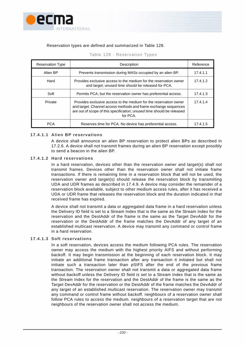
Reservation types are defined and summarized in Table 128.
17.4.1.1 Alien BP reservationsA device shall announce an alien BP reservation to protect alien BPs as described in17.2.6. A device shall not transmit frames during an alien BP reservation except possiblyto send a beacon in the alien BP.
17.4.1.2 Hard reservationsIn a hard reservation, devices other than the reservation owner and target(s) shall nottransmit frames. Devices other than the reservation owner shall not initiate frametransactions. If there is remaining time in a reservation block that will not be used, thereservation owner and target(s) should release the reservation block by transmittingUDA and UDR frames as described in 17.4.9. A device may consider the remainder of areservation block available, subject to other medium access rules, after it has received aUDA or UDR frame that releases the reservation block and the duration indicated in thatreceived frame has expired.
A device shall not transmit a data or aggregated data frame in a hard reservation unlessthe Delivery ID field is set to a Stream Index that is the same as the Stream Index for thereservation and the DestAddr of the frame is the same as the Target DevAddr for thereservation or the DestAddr of the frame matches the DevAddr of any target of anestablished multicast reservation. A device may transmit any command or control framein a hard reservation.
17.4.1.3 Soft reservationsIn a soft reservation, devices access the medium following PCA rules. The reservationowner may access the medium with the highest priority AIFS and without performingbackoff. It may begin transmission at the beginning of each reservation block. It mayinitiate an additional frame transaction after any transaction it initiated but shall notinitiate such a transaction later than pSIFS after the end of the previous frametransaction. The reservation owner shall not transmit a data or aggregated data framewithout backoff unless the Delivery ID field is set to a Stream Index that is the same asthe Stream Index for the reservation and the DestAddr of the frame is the same as theTarget DevAddr for the reservation or the DestAddr of the frame matches the DevAddr ofany target of an established multicast reservation. The reservation owner may transmitany command or control frame without backoff. neighbours of a reservation owner shallfollow PCA rules to access the medium. neighbours of a reservation target that are notneighbours of the reservation owner shall not access the medium.
Table 128 - Reservat ion Types
Reservation Type Description Reference
Alien BP Prevents transmission during MASs occupied by an alien BP. 17.4.1.1
Hard Provides exclusive access to the medium for the reservation owner and target; unused time should be released for PCA.
17.4.1.2
Soft Permits PCA, but the reservation owner has preferential access. 17.4.1.3
Private Provides exclusive access to the medium for the reservation owner and target. Channel access methods and frame exchange sequences are out of scope of this specification; unused time should be released
for PCA.
17.4.1.4
PCA Reserves time for PCA. No device has preferential access. 17.4.1.5
- 220 -

17.4.1.4 Private reservationsThe channel access method and frame exchange sequences used during a privatereservation are out of the scope of this Standard. A device shall use standard frameformats and frame type and frame subtype field values in frames transmitted within aprivate reservation. In a private reservation, devices other than the reservation ownerand target(s) shall not transmit frames. If there is remaining time unused during areservation block, the reservation owner and target(s) should release the reservationblock by transmitting UDA and UDR frames. A device may consider the remainder of thereservation block available, subject to other medium access rules, after it has received aUDA or UDR frame that releases the reservation block and the duration indicated in thatreceived frame has expired, as described in 17.4.9.
17.4.1.5 PCA reservationsDuring a PCA reservation, any device may access the medium using PCA rules.
17.4.2 Medium accessA device shall not transmit a unicast frame within a reserved MAS in a hard, soft, or privatereservation in the current superframe unless:
• it included a DRP IE with the Reservation Status bit set to ONE that included that MAS in itsbeacon in the previous superframe;
• the destination device is a neighbour; and
• the most-recently received beacon from the destination device included a DRP IE with theReservation Status bit set to ONE that included that MAS.
A device shall not transmit a multicast frame within a reserved MAS in a hard, soft, orprivate reservation in the current superframe unless:
• it included a DRP IE with the Reservation Status bit set to ONE that included that MAS in itsbeacon in the previous superframe;
17.4.3 DRP availabil i ty IEThe DRP Availability IE identifies the MASs where a device is able to establish a new DRPreservation.
The combination of information from DRP Availability IEs and DRP IEs allows an owner todetermine an appropriate time for a new DRP reservation. In order to facilitate the DRPnegotiation process, devices that are aware of existing neighbours' DRP reservationsshould mark the reserved MASs as unavailable.
A device should mark a MAS unavailable if the device includes it in a DRP IE with theReservation Status bit set to ONE. It should mark a MAS unavailable if a neighbourincludes it in a DRP IE with a target other than the device, whether the Reservation Statusbit is ZERO or ONE. It shall mark a MAS unavailable if any BP occupies any portion of thatMAS, based on information in any beacon received in the latest mMaxLostBeacons+1superframes.
17.4.4 DRP reservation negotiationThere are two mechanisms used to negotiate a reservation: explicit and implicit. Forexplicit negotiation, the reservation owner and target use DRP Reservation Request andDRP Reservation Response command frames to negotiate the desired reservation. Forimplicit negotiation, the reservation owner and target use DRP IEs transmitted in theirbeacons. For either negotiation mechanism, the reservation owner completes thenegotiation by including an appropriate DRP IE in its beacon.
A device shall not negotiate for MASs that are included in a DRP IE received from aneighbour or any other DRP IE included in the device's beacon, unless the MASs arereferenced only in a DRP IE with Reason Code set to Denied.
- 221 -
A device shall announce in the MAC Capabilities IE in its beacon whether it is capable ofexplicit DRP negotiation. A device shall not initiate an explicit DRP negotiation withdevices that do not support it.
A device shall only initiate negotiation for a reservation as the reservation owner.
For reservations of type Alien BP, there is no negotiation with neighbours. A device shallinclude the appropriate DRP IE with Reservation Status set to ONE on detection of an alienBP, as specified in 17.2.6.
For reservations of type PCA, there is no negotiation with neighbours. A device may selectany available MAS to include in a reservation of type PCA. The device shall not set theReservation Status bit to ONE in a PCA reservation unless it included a DRP IE in itsbeacon in the previous superframe that identified the same MASs, with Reservation Typeset to PCA and Reservation Status set to ZERO or ONE.
17.4.4.1 Negotiat ionWhen negotiating a reservation, the reservation owner shall set the Target/OwnerDevAddr field of the DRP IE to the DevAddr of the reservation target. It shall set theReservation Status bit to ZERO and the Reason Code to Accepted in the DRP IE. Fornew streams, the Stream Index shall be set to a value that is currently not used with thisTarget DevAddr and has not been used as such for mMaxLostBeacons+1 superframes.To negotiate additional MASs for an existing stream, the Stream Index shall be set to thevalue used for the existing stream.
When negotiating a reservation, a reservation target shall set the Target/Owner DevAddrfield of the DRP IE to the DevAddr of the reservation owner. If a unicast reservation isgranted, it shall set the Reservation Status bit to ONE and the Reason Code toAccepted. If a multicast reservation is granted, it shall set the Reservation Status bit tothe same value included in the DRP IE by the reservation owner, and shall set theReason Code to Accepted. If the reservation is not granted, it shall set the ReservationStatus bit to ZERO. If the reservation cannot be granted due to a conflict with its own orits neighbours' reservations, the reservation target shall set the Reason Code toConflict. If the reservation is not granted, it shall set the Reason Code to Denied. If thereservation target cannot grant the reservation immediately, it may set the Reason Codeto Pending, and deliver a final response later. For a unicast reservation, the reservationtarget shall set the DRP Allocation fields to match those in the request. For a multicastreservation, it shall set the DRP Allocation fields to match the request, or to include asubset of the MASs included in the request.
17.4.4.2 Explicit negotiat ionTo start explicit DRP negotiation, the reservation owner shall send a DRP ReservationRequest command frame to the target device, as defined in 16.5.1.
On reception of a DRP Reservation Request command the reservation target shall senda DRP Reservation Response command, as defined in 16.5.2, to the reservation owner.The fields in the DRP IE shall be set according to 17.4.4.1. If the reservation cannot begranted due to a conflict with its own or its neighbours' reservations, the reservationtarget shall include a DRP Availability IE in the DRP Reservation Response commandframe.
In a DRP Reservation Response command frame for a multicast reservation, thereservation target shall include a DRP Availability IE for a Reason Code other thanDenied. Final multicast reservations are established implicitly, as described in 17.4.4.3.
17.4.4.3 Implicit negotiat ionImplicit negotiation is carried out by transmitting DRP IE(s) in beacon frames. A devicethat supports the DRP shall parse all beacons received from neighbours for DRP IE(s)whose Target/Owner DevAddr field matches either the device's DevAddr or a multicast
- 222 -

DevAddr for which the device has activated multicast reception. From this initialselection, the device shall process the DRP IE(s) that are new with respect to DRP IE(s)included in the most recently received beacon from the same device as a DRPreservation request or a DRP reservation response.
To start implicit negotiation, a reservation owner shall include a DRP IE that describesthe proposed reservation in its beacon. The device should continue to include the DRPIE for at least mMaxLostBeacons+1 consecutive superframes or until a response isreceived.
On reception of a unicast DRP reservation request in a beacon, the reservation targetshall include a DRP reservation response in its beacon no later than the nextsuperframe, with fields set as described in 17.4.4.1. If the Reason Code indicatesConflict, the reservation target shall include a DRP Availability IE in its beacon.
As long as the reservation owner includes a unicast DRP reservation request in itsbeacon, the reservation target shall continue to include the DRP reservation response inits beacon. The reservation target shall not change the Reservation Status bit to ONE ifthere is a reservation conflict with its neighbours.
On reception of a multicast DRP reservation request, a reservation target shall include areservation response DRP IE in its beacon no later than the next superframe if it is amember of the targeted multicast group. The fields in the DRP IE shall be set accordingto 17.4.4.1. If the Reservation Status bit in the response is ZERO, the reservation targetshall include a DRP Availability IE in its beacon unless the Reason Code is set toDenied.
A device that elects to receive traffic in an already established multicast reservationdoes not negotiate the reservation. To join an established multicast reservation thatdoes not conflict with other existing reservations, a device shall include correspondingDRP IE(s) in its beacon with Reservation Status bit set to ONE and Reason Code set toAccepted.
A device that cannot join an established multicast reservation because of an availabilityconflict may inform the source by including the corresponding DRP IE(s) in its beaconwith Reservation Status bit set to ZERO, and the Reason Code set to Conflict. Thedevice shall also include the DRP Availability IE in the beacon.
17.4.4.4 Negotiat ion conclusionTo conclude negotiation for a unicast reservation, the reservation owner shall setReservation Status to ONE in the DRP IE in its beacon after receiving a beacon from thereservation target that contains a corresponding DRP IE with Reservation Status set toONE. To conclude negotiation for a multicast reservation, the reservation owner may setReservation Status to ONE in a DRP IE in its beacon in the next superframe aftertransmitting the same DRP IE with Reservation Status set to ZERO, regardless ofresponses from potential multicast recipients. If a reservation conflict exists, thereservation owner shall not set the Reservation Status bit to ONE except as specified in17.4.6.
17.4.5 DRP reservation announcementsOnce negotiation for a reservation successfully completes, the reservation owner andtarget shall include DRP IE(s) in their beacons that describe the reservation. Within eachDRP IE, the Reason Code shall be set to Accepted and the Reservation Status bit shall beset to ONE. The devices shall include the DRP IEs in each beacon transmitted until thereservation is modified or terminated.
17.4.6 Resolution of DRP reservat ion confl ictsDevices engaged in independent DRP negotiation could attempt to reserve the same MAS,or due to mobility, devices could have reserved the same MAS. A conflict exists between
- 223 -

DRP reservations if a MAS is included in both reservations. A device might detect a conflictduring a DRP negotiation or after a reservation has been established. Reservations of typeAlien BP never conflict with other reservations of type Alien BP. Reservations of type PCAnever conflict with other reservations of type PCA.
A device shall apply the following rules to a conflict between a DRP IE included in itsbeacon and another DRP IE included by a neighbour, unless the neighbour's DRP IEOwner/Target DevAddr field identifies the device, or the neighbour's DRP IE has the sameStream Index, Reservation Type, Owner, and Owner/Target DevAddr fields as the device'sDRP IE and the device's DRP IE is in response to a multicast reservation:
1) If the device's reservation is of type Alien BP, the device shall maintain the reservation.
2) If the neighbour’s reservation is of type Alien BP, the device shall not transmit framesin conflicting MASs in the following superframe. If the device is the reservation target,it shall also set the Reason Code in its DRP IE to Conflict in its beacon in the followingsuperframe.
3) If the device's DRP IE has the Reservation Status bit set to ZERO and the neighbour’sDRP IE has the Reservation Status bit set to ONE, the device shall not set theReservation Status bit to ONE and shall not transmit frames in conflicting MASs. If thedevice is the reservation target, it shall also set the Reason Code in its DRP IE toConflict.
4) If the device's DRP IE has the Reservation Status bit set to ONE and the neighbour’sDRP IE has the Reservation Status bit set to ZERO, the device may maintain thereservation.
5) If the device's DRP IE and neighbour’s DRP IE have the Reservation Status bit set tothe same value and one of the following conditions is true, the device may maintain thereservation.
a) The device's DRP IE and neighbour’s DRP IE have the Conflict Tie-breaker bit setto the same value and the device's occupied beacon slot number is lower than thebeacon slot number of the neighbour; or
b) The device's DRP IE and neighbour’s DRP IE have the Conflict Tie-breaker bit setto different values and the device's occupied beacon slot number is higher thanthe beacon slot number of the neighbour.
6) If the device's DRP IE and neighbour’s DRP IE have the Reservation Status bit set toZERO and one of the following conditions is true, the device shall not set theReservation Status bit to ONE. If the device is the reservation target, it shall set theReason Code in its DRP IE to Conflict.
a) The device's DRP IE and neighbour’s DRP IE have the Conflict Tie-breaker bit setto the same value and the device's occupied beacon slot number is higher thanthe beacon slot number of the neighbour; or
b) The device's DRP IE and neighbour’s DRP IE have the Conflict Tie-breaker bit setto different values and the device's occupied beacon slot number is lower than thebeacon slot number of the neighbour.
7) If the device's DRP IE and neighbour’s DRP IE have the Reservation Status bit set toONE and one of the following conditions is true, the device shall not transmit frames inconflicting MASs in the following superframe. It shall remove the conflicting MASs fromthe reservation or set the Reservation Status to ZERO in its beacon in the followingsuperframe. If the device is the reservation target, it shall also set the Reason Code inits DRP IE to Conflict.
- 224 -

a) The device's DRP IE and neighbour’s DRP IE have the Conflict Tie-breaker bit setto the same value and the device's occupied beacon slot number is higher thanthe beacon slot number of the neighbour; or
b) The device's DRP IE and neighbour’s DRP IE have the Conflict Tie-breaker bit setto different values and the device's occupied beacon slot number is lower than thebeacon slot number of the neighbour.
When a reservation owner withdraws a reservation or part of a reservation due to aconflict, it shall invoke a backoff procedure prior to requesting additional MASs in anyreservation. The device shall initialize the backoff window BackoffWin tomDRPBackoffWinMin. When the backoff algorithm is invoked, the device shall select arandom number N uniformly from [0, BackoffWin-1]. The device shall not request additionalMASs for N superframes. If a further negotiation fails due to a conflict, the device shalldouble BackoffWin, up to a maximum of mDRPBackoffWinMax. After a negotiationcompletes, the device shall generate a new backoff N. If a device does not request anyMASs for 4×BackoffWin superframes, the device may terminate this backoff procedure andrequest MASs at any time unless another conflict occurs.
If a reservation target sets Reason Code to Conflict in any DRP IE in its beacon, it shallinclude a DRP Availability IE in the same beacon.
17.4.7 BPST realignment and existing DRP reservationsA device that realigns its BPST as described in 17.2.6 may assert new DRP reservationswith Reservation Status bits set to ONE in the new beacon so long as they are equivalentto its old DRP reservations with the Reservation Status bit set to ONE in the prior BP. Forthis purpose, two DRP reservations are equivalent if their target and owner are the same,their corresponding Stream Index and Reservation Type fields are the same and thenumber of MASs claimed by the new reservation is less than or equal to the numberclaimed by the old reservation.
A device that realigns its BPST shall not assert DRP reservations with MASs that conflictwith any BP it announced or detected. The device shall not assert DRP reservations withMASs that conflict with reservations with Reservation Status equal to one announced in thenew BP unless no other MASs are available. Any conflict with existing reservations shallbe resolved according to the procedures specified in 17.4.6.
17.4.8 Modif ication and termination of exist ing DRP reservat ionsA reservation owner may reserve additional MASs for a stream by negotiating an additionto the reservation using a DRP IE with the same Target/Owner DevAddr, Stream Index, andReservation Type. Once negotiation has completed successfully, the reservation ownershould combine the DRP IEs. When combining DRP IEs, the reservation owner shall setthe Reason Code to Modified until a DRP IE is received from the reservation target thatdescribes the combined reservation.
A reservation owner may remove MASs from an established reservation without changingthe Reservation Status bit in the DRP IE. If a reservation owner removes some MASs froman established reservation, it shall set the Reason Code in its DRP IE to Modified until thereservation target has changed its DRP IE to match.
A reservation target may remove MASs from an established reservation without changingthe Reservation Status bit in the DRP IE due to a conflict, as described in 17.4.6 or due toreception of a Relinquish Request IE. If the reservation target is unicast, the reservationowner shall remove the same MASs from the reservation or terminate the reservation inthe current or following superframe.
To terminate a reservation, the reservation owner shall remove the DRP IE from itsbeacon.
- 225 -

If a reservation owner changes or removes a DRP IE, the reservation targets shall updateor remove the corresponding DRP IE from their beacons in the current or followingsuperframe. This also permits a reservation owner and target that decide to modify or dropa reservation through other means to modify or remove the relevant DRP IEs from theirbeacons in the same superframe.
To terminate a reservation, a reservation target shall set the Reservation Status bit toZERO and the Reason Code to an appropriate value, as if responding to an initialreservation request. The reservation owner shall terminate the corresponding reservationor set the corresponding Reservation Status bit to ZERO in the current or followingsuperframe.
If a reservation owner or target does not receive a beacon or any other frame from theother participant in the reservation for more than mMaxLostBeacons superframes, it shallconsider the reservation terminated, and shall remove the corresponding DRP IE(s) fromits beacon.
17.4.9 Release of hard or private DRP reservation blocksIf time remains in a hard or private DRP reservation block after a reservation ownercompletes transmission of associated buffered traffic, it should release the reservationblock by sending a UDA frame. If the remaining time in the reservation block is notsufficient for the exchange of UDA and UDR control frames, no action should be taken.The transmitter of the UDA control frame shall include a list of device(s) that shall respondto this announcement. The list should consist of those devices that have previouslyincluded the corresponding DRP IE(s) in their beacons. The order in which the DevAddrsof the devices are mentioned in the list is the order in which they shall respond with a UDRcontrol frame. This allows devices around the transmitter as well as the devices in the listto be informed about the early end of the reservation block.
On reception of a UDA control frame that includes its DevAddr in the device list, a deviceshould respond with a UDR control frame. A device shall transmit a UDR control frameafter a delay given by:
Time to send Response = pSIFS + pSlotTime + (Position_in_list_in_UDA) × (UDR_control_frame_duration + pSIFS)
Time to send Response is calculated from the end of reception of the UDA control frame.Possible values of Position_in_list_in_UDA are in the range [0, N-1], inclusive.
UDA and UDR control frames release the time between the end of PLCP header of the lastUDR control frame, as indicated by the Duration value in the MAC header of UDA and UDRcontrol frames, and the end of the reservation block. Other MASs described by thereservation that do not belong to the current reservation block, either in the samesuperframe or following superframes, are not released.
The Duration value in the UDA control frame shall cover the UDA control as well as allexpected UDR control frames. The Duration value in the UDR control frames shall be setto the Duration value in the UDA control frame minus the time between the end of thePLCP header of the UDA control frame and the end of the respective UDR control frame.This value is given by the following equation:
Duration value in UDR = Duration value in UDA - (UDA_frame_body_transmission_time + pSIFS + pSlotTime + (Position_in_list_in_UDA) × (UDR_control_frame_transmission_time + pSIFS)) - UDR_control_frame_transmission_time.
17.4.10 Retransmit procedures in DRP reservationsIn a hard DRP reservation block, if the reservation owner transmits a frame with ACKPolicy set to Imm-ACK or B-ACK, but does not receive the expected acknowledgement
- 226 -

frame, it may retransmit the frame within the same reservation block if the reservationblock has not been released.
In a soft DRP reservation block, the reservation owner may retransmit a frame with nobackoff, as described in 17.4.1.3. Devices other than the reservation owner that retransmitframes in a soft DRP reservation block shall follow the PCA rules defined in 17.3.
A device shall not retransmit a frame earlier than pSIFS after the end of an expectedacknowledgement or CTS frame, whether or not it receives the expected frame. A deviceshall not retransmit a frame in the current reservation block if there is not enough timeremaining in the reservation block for the entire frame transaction.
17.5 Synchronization of devicesEach device shall maintain a beacon period start time (BPST). The device shall derive alltimes for communication with its neighbours based on the current BPST. The device shalladjust its BPST in order to maintain superframe synchronization with its slowest neighbour. Adevice shall synchronize with such a device before it sends its first beacon.
When a device receives a beacon from a neighbour, the device determines the differencebetween the beacon's actual reception time and the expected reception time. The beacon'sactual reception time is an estimate of the time that the start of the beacon preamble arrivedat the receiving device's antenna. The expected reception time is determined from theBeacon Slot Number field of the received beacon and the receiving device's BPST. If thedifference is positive, then the neighbour is slower. In order to maintain superframesynchronization with a slower neighbour, the device shall delay its BPST by the difference,but shall limit the adjustment to a maximum of mMaxSynchronizationAdjustment persuperframe. This might require adjustment of its BPST in multiple superframes, based on thelatest BPST observed via any beacon received from a neighbour in the lastmMaxLostBeacons+1 superframes. A device must consider its own sampling and round-offerror in calculating the BPST difference, and shall ensure that the BPST it indicates via itsbeacon is not later than the known or estimated BPST of its slowest neighbour in theprevious superframe. The adjustment to BPST may occur at any time following the detectionof a slower device, but shall be done before the end of the superframe.
A device shall not use a beacon with the Signaling Slot bit set for synchronization.
If a device does not receive a beacon from a neighbour, the device may use historicalmeasurements to estimate the impact on superframe synchronization and increment its BPSTaccordingly. This estimate may be applied for up to mMaxLostBeacons consecutivesuperframes.
Beacon transmit time and measured beacon receive time shall be accurate to at leastmClockResolution.
17.5.1 Clock accuracyMAC sublayers shall maintain a clock at least as accurate as mClockAccuracy. All timemeasurements, such as MAS boundary and frame reception time measurements, shall bemeasured with a minimum resolution of mClockResolution.
17.5.2 Synchronizat ion for devices in hibernation modeDevices in hibernation mode may become unsynchronized beyond the mGuardTime valueduring hibernation. Prior to returning to active mode and sending a beacon, a device inhibernation mode shall wake up at least one superframe plus the maximum possible driftduring its hibernation, and shall realign its BPST to its slowest neighbour without regard tothe mMaxSynchronizationLimit.
17.5.3 Guard t imesDue to inaccuracies in superframe synchronization and drift between synchronizationevents, MAS start times for different devices are not synchronized perfectly. To ensure a
- 227 -

full SIFS interval between transmissions in adjacent MASs, the devices shall maintain atleast a SIFS interval and guard interval at the end of a reservation block. Guard timesapply to all boundaries of DRP reservation blocks and BPs.
Figure 105 is an illustration of how a device uses the guard interval to maintain a SIFSinterval between transmissions in adjacent reservation blocks.
The length of the guard interval, mGuardTime, depends on the maximum differencebetween devices' MAS boundary times. The difference arises from synchronization errorand drift. The guard time is determined as follows:
mGuardTime = MaxSynchronizationError + MaxDrift,
where MaxSynchronizationError is the worst case error in superframe synchronization andMaxDrift is the worst case drift.
Synchronization is achieved during the BP as described in 17.5. For purposes ofdetermining guard time, MaxSynchronizationError is calculated as twicemClockResolution.
Drift is a function of the clock accuracy and the time elapsed (SynchronizationInterval)since a synchronization event. The maximum drift, MaxDrift, is calculated using the worstcase value for clock accuracy, mClockAccuracy, and the longest SynchronizationInterval:
MaxDrift = 2 × mClockAccuracy (ppm) × 1E-6 × SynchronizationInterval,
where
SynchronizationInterval = (mMaxLostBeacons+1) × mSuperframeLength.
Propagation delay will also affect timing uncertainty, but in a short-range networkpropagation delays are small. At 10 m range, the propagation delay is around 33 ns. Thisis much smaller than mClockResolution and it is ignored in calculating the length of theguard interval.
A device transmitting in a reservation block may start transmission of the preamble for thefirst frame at the point where it calculates the start of the reservation block to be based onits local clock. For frames that use No-ACK or B-ACK acknowledgement policy, thetransmitting device shall ensure that there is enough time remaining in the reservation
Slower DEV TX SIFS Guard
Faster DEV TX
Faster DEV MAS boundary
Slower DEV MAS boundary
Figure 105 - Guard Time
- 228 -

block to transmit the frame and allow for a SIFS plus mGuardTime before the end of thereservation block as calculated by that device.
If Imm-ACK is used, or a B-ACK is requested by the last frame, the transmitting deviceshall also ensure there is enough time for a SIFS interval, the ACK, another SIFS interval,and the guard time, as defined in Figure 107.
A device shall be able to receive a frame that is transmitted within the bounds of allowabletransmission, accounting for the worst case drift. A device shall begin listeningmGuardTime prior to the start of a DRP reservation block, the start of a BP, or the start of aMAS in which the device announced it would be available.
17.6 Fragmentation and reassemblyA source device may fragment each MSDU/MCDU.
A device shall not fragment any MSDU/MCDU to more than mMaxFragmentCount fragments.Fragments may be of varying sizes. Once a device transmits a frame containing a wholeMSDU/MCDU or a fragment thereof, the device shall not fragment or refragment the frame.The device shall not create frame fragments smaller than mMinFragmentSize.
The device shall set the Fragment Number field in the first fragment to zero. It shall set eachsubsequent fragment to the Fragment Number field in the previous fragment plus one. Thedevice shall not increment the Fragment Number field when a fragment is retransmitted.
A device shall assign the same Sequence Number to all fragments of an MSDU/MCDU.
The device shall completely reassemble an MSDU/MCDU in the correct order before deliveryto the MAC client. The device shall discard any MSDU/MCDU with missing fragments. If theNo-ACK policy is used, the recipient device shall discard an MSDU/MCDU immediately if afragment is missing. Otherwise, a recipient device shall discard the fragments of an MSDU ifthe MSDU is not completely received within an implementation-dependent timeout.
If B-ACK is used, unacknowledged fragments from multiple MSDUs belonging to the samestream may be retransmitted in the same sequence. In this case it is the responsibility of therecipient device to deliver the MSDUs in the correct order to the MAC client.
If a source device discards a fragment of an MSDU/MCDU, the device shall discard allfragments of the MSDU/MCDU.
FrameSIFS
or MIFS
FrameSIFS
or MIFS
Frame SIFS Guard
End of reservation block
Start of reservation block
Figure 106 - SIFS and guard time in a DRP reservation block - No-ACK
Frame SIFSACKSIFS Frame SIFSACKSIFS Frame SIFSACKSIFS Guard
End of reservation block
Start of reservation block
Figure 107 - SIFS and Guard Time in a DRP reservation block - Imm-ACK
- 229 -

17.7 AggregationA transmitter may aggregate multiple MSDUs with identical Delivery ID into a single framepayload. A device shall aggregate no more than mAggregationLimit MSDUs into anaggregated data frame.
A single MAC header is associated with an aggregated payload and it shall apply equally toeach MSDU in the aggregated payload. In terms of acknowledgement and retransmission,both the transmitter and receiver shall treat the aggregated payload as a single indivisibleentity. On receiving an aggregated data frame, the recipient shall deliver MSDUs from theaggregated payload to its MAC client maintaining the ordering from the payload.
The aggregated MSDUs shall be aligned on 4-octet boundaries. Prior to each MSDU, 0 to 3pad octets shall be inserted such that the MSDU starts on a 4-octet boundary.
17.8 Acknowledgement policiesThis Clause defines three acknowledgement policies: no acknowledgement (No-ACK),immediate acknowledgement (Imm-ACK) and block acknowledgement (B-ACK).
A device shall acknowledge all received unicast frames with the ACK Policy field set to Imm-ACK, B-ACK or B-ACK Request and the DestAddr field set to the DevAddr of this device. Thedevice shall acknowledge the reception without regard to security validation. A device thatreceives a frame with a higher Protocol Version than it supports shall discard the framewithout acknowledgement.
17.8.1 No-ACKA frame with ACK policy set to No-ACK, as defined in 16.2.1.3, shall not be acknowledgedby the recipient. The transmitting device MAC sublayer assumes the frame has beensuccessfully transmitted and proceeds to the next frame upon completion of current frame.All broadcast and multicast frames shall have ACK Policy set to No-ACK.
17.8.2 Immediate ACKOn reception of a frame with ACK Policy set to Imm-ACK, a device shall respond with anImm-ACK frame, as defined in 16.4.1, transmitted pSIFS after the end of the receivedframe.
17.8.3 Block ACKThe B-ACK mechanism allows a source device to transmit multiple frames and to receive asingle acknowledgement frame from the recipient indicating which frames were receivedand which need to be retransmitted.
A source device initiates the use of the B-ACK mechanism with a recipient device forframes either from the same stream or of the same user priority. If the recipient deviceaccepts use of the B-ACK mechanism, it indicates the maximum number and size of theframes it can buffer. The source device transmits a sequence of frames to the recipient,each from the same stream or of the same user priority, limited by the announced buffersize and maximum number of frames. The initial frames in the sequence are all transmittedwith ACK Policy set to B-ACK. The final frame in the sequence is transmitted with ACKPolicy set to B-ACK Request. On receipt of such a frame, the recipient device returns a B-ACK frame giving feedback on the frames received and indicating the buffer spaceavailable for the next B-ACK sequence.
A source device may invoke multiple instances of the B-ACK mechanism with the samerecipient device, each for a different stream or user priority. A source device may alsoinvoke the B-ACK mechanism with multiple recipient devices.
17.8.3.1 Init iat ionA source device may activate the B-ACK mechanism independently for any stream oruser priority traffic to any potential recipient device advertising B-ACK capability in its
- 230 -

MAC Capabilities IE. A source device shall initiate use of the B-ACK mechanism bytransmitting a frame with ACK Policy set to B-ACK Request to the recipient device. Asource device shall use a dedicated Sequence Number counter for each stream or userpriority traffic using the B-ACK mechanism with a recipient. After transmitting the frame,the source device shall follow the rules of operation as described in 17.8.3.2.
When receiving a frame with ACK Policy set to B-ACK Request from a source device fora stream or user priority traffic not currently using the B-ACK mechanism, the recipientdevice shall respond as follows:
- To acknowledge receipt of the frame but reject the request for starting a new instanceof B-ACK mechanism, the recipient device shall respond with a B-ACK frame with noframe payload.
- To accept the request for starting a new instance of B-ACK mechanism, the recipientdevice shall respond with a B-ACK frame with a frame payload indicating the allowedmaximum size (in frames and octets) for the next B-ACK sequence. The recipientshall acknowledge the received frame by indicating its reception in theacknowledgement window.
A recipient device may also accept a request to use the B-ACK mechanism even if therequest frame has an invalid FCS. To accomplish this, the recipient device shall respondwith a B-ACK frame with a frame payload that indicates the allowed maximum size forthe next B-ACK sequence, but without acknowledgement of the frame with the invalidFCS.
A recipient device, even though it advertises B-ACK capability in its MAC Capabilities IE,may reject a request to use the B-ACK mechanism for any reason, including a temporaryunavailability of resources or a lengthy setup process requiring a delayed start time.Thus, after being rejected, a source device may keep trying to initiate use of the B-ACKmechanism by sending the next frame with ACK Policy set to B-ACK Request.
17.8.3.2 OperationAfter transmitting a frame with ACK Policy set to B-ACK Request, the source deviceexpects to receive a B-ACK frame in response and takes one of the following actions:
• If the source device does not receive a B-ACK frame, it shall assume that the recipientdevice did not receive the request frame. To continue B-ACK operation, the source deviceshall retransmit the request frame with the same ACK Policy using applicable mediumaccess rules as described in 17.3 and 17.4.
• If the source device receives a B-ACK frame with no frame payload, it shall treat thetransmitted frame as received and consider this use of the B-ACK mechanism to beterminated. The B-ACK provides no acknowledgement of any other frames.
• If the source device receives a B-ACK frame with a frame payload and with either FrameCount or Buffer Size set to zero, it shall process the acknowledgement as describedbelow. To continue the B-ACK operation, the source device shall retransmit therequesting frame with the same ACK Policy, independently of whether the frame wasindicated as received or not. If the requesting frame was indicated as received, thesource device alternatively may transmit a zero-length payload frame with the sameSequence Control and Delivery ID to the recipient device.
• If the source device receives a B-ACK frame with a frame payload containing non-zerovalues for both Frame Count and Buffer Size, then it shall process the acknowledgementas described below. To continue the B-ACK operation, the source device shall sendframes with ACK Policy set to B-ACK or B-ACK Request as described below.
- 231 -

The source device processes the B-ACK frame acknowledgement as follows:
• Frames being held for retransmission with a sequence number earlier than the oneindicated by the Sequence Control field were not received in the last B-ACK sequence,but shall not be retransmitted.
• Frames being held for retransmission with sequence and fragment number within theacknowledgement window (specified by the Sequence Control field and the FrameBitmap field) with corresponding bit set to ONE were received and shall not beretransmitted.
• Other frames being held for retransmission shall be retransmitted within the nextmMaxBlockACKSequences sequences, ordered by increasing sequence and fragmentnumbers, unless the frames will never be retransmitted.
After receiving a B-ACK frame with non-zero values for Frame Count and Buffer Size,the source device may transmit a sequence of frames. Each sequence of frames shallconsist of zero or more frames with ACK Policy set to B-ACK followed by a single framewith ACK Policy set to B-ACK Request. The total number of frames must not exceed theFrame Count value specified in the B-ACK frame and the sum of the lengths of the framepayloads shall not exceed the Buffer Size value specified in the B-ACK frame. Thesequence of frames may be transmitted in multiple PCA TXOPs or DRP reservationblocks and may be interleaved with frames to other recipients or of other streams or userpriorities, subject to all the medium access rules. Within a sequence, the frames shall beordered by increasing sequence and fragment numbers. Due to retransmissions, thisordering might not hold from one sequence to the next and frames transmitted within asequence might not have consecutive sequence and fragment numbers.
When the recipient device receives a frame with ACK Policy set to B-ACK Request, itshall respond using SIFS with a B-ACK frame. To continue operation, the B-ACK frameshall contain a frame payload. If the recipient device receives a frame with a valid HCSbut an invalid FCS and with ACK Policy set to B-ACK Request, the device shall alsorespond with a B-ACK frame with a frame payload. Within the B-ACK frame payload, therecipient device shall set the Frame Count and Buffer Size fields to limit the size of thenext sequence of frames. It shall also set the Sequence Control and Frame Bitmap fieldsto indicate to the source device which frames should be retransmitted.
A recipient device may implement a timeout that indicates when to stop waiting formissing frames, allowing some MSDUs to be released to the MAC client and B-ACKbuffer resources to be freed. A recipient device may also implement a timeout to expirean instance of the B-ACK mechanism that appears to be inactive.
17.8.3.3 TerminationTo terminate use of the B-ACK mechanism, the source device shall transmit a framefrom the appropriate stream or of the appropriate user priority to the recipient devicewith ACK Policy set to anything other than B-ACK or B-ACK Request.
The recipient device may terminate use of the B-ACK mechanism by responding to aframe with ACK Policy set to B-ACK Request with a B-ACK frame with no frame payload.To terminate cleanly, a recipient device should send one or more B-ACK frames with theFrame Count field set to one, so that the sending device can transmit remainingunacknowledged frames and receive acknowledgements for them.
17.9 ProbeThe Probe IE and Application-specific Probe IE may be used in beacons and probecommands to request one or more IEs from the target device identified in the probe IE. Targetdevices are not required to respond with all requested IEs. If a target device supports theProbe command frame for one or more IEs, it shall set the Probe bit in its MAC CapabilitiesIE to ONE, or otherwise it shall set the bit to ZERO.
- 232 -

A device shall include a MAC Capabilities IE or a PHY Capabilities IE in its beacon if it is thetarget of a Probe IE received in a beacon that includes the MAC Capabilities IE Element ID orthe PHY Capabilities IE Element ID, respectively.
On reception of either probe IE in a beacon, a target device shall include a response in itsbeacon for the next mMaxLostBeacons superframes.
On reception of either probe IE in a Probe command frame, a target device should respondwith a Probe command frame addressed to the sender within one superframe or include aresponse in its beacon for the next mMaxLostBeacons superframes.
In the Probe command frame or beacon, the target device shall include:
• A Probe IE, with Target DevAddr set to the DevAddr of the requestor, that includes noRequested Element IEs to reject the probe; or
• One or more requested IEs.
17.10 Dynamic channel selectionDynamic channel selection is a process that allows a group of devices to change channels ina coordinated manner.
A device may initiate dynamic channel selection after it has performed a channel scan, asdescribed in 17.2.3. If a device initiates dynamic channel selection, it shall include a ChannelChange IE in its beacon sent in the current channel, as described in 16.8.5.
In a Channel Change IE, the device shall set the New Channel Number field to the number ofthe new channel. It shall set the Change Channel Count field to the remaining number ofsuperframes before the device will move to another channel. In successive superframes, theChange Channel Count field should be decremented.
If the value set in the Change Channel Count field is zero, the device shall move to the newchannel at the end of the current superframe.
On reception of the Channel Change IE, a device that also intends to change channels in acoordinated manner should include a Channel Change IE with the same field values in itsbeacon.
17.11 Multi-rate supportA device shall transmit beacons at pBeaconTransmitRate.
Devices shall transmit non-beacon frames only at data rates supported by the intendedrecipient, based on information from the recipient's PHY Capabilities IE.
A recipient device may use the Link Feedback IE to suggest the optimal data rate to be usedby a source device, for example, to increase throughput and/or to reduce the frame errorrate. The data rate in the Link Feedback IE should be interpreted as the maximum data ratethat the source device should use for this particular link, for an acceptable frame error rate.The source device is not required to follow the recommendation. The method to determinethe optimal data rate in the recipient is beyond the scope of this Standard.
17.12 Transmit power controlA device shall not transmit frames at a higher transmit power level than that used for its most-recently transmitted beacon.
A recipient device may recommend a transmit power level change to be used by a sourcedevice by including a Link Feedback IE in its beacon. A device that receives a Link FeedbackIE is not required to change its transmit power level. The method to determine transmit powerrecommendations is out of the scope of this Standard, but the recipient device might use thesignal to noise ratio, received signal strength, frame error ratio or other parameters todetermine the transmit power change to recommend to the source device.
- 233 -

17.13 Power management mechanisms17.13.1 Power management modes
A device may be in one of two power management modes in each superframe:
• Active mode: the device will send and receive beacon(s) in the current superframe.
• Hibernation mode: the device will not send a beacon or other frames in the currentsuperframe.
Before entering hibernation mode, a device shall announce in previous superframe(s) thatit is entering hibernation mode.
17.13.2 Device power statesActive mode devices may be in one of two power states within a superframe:
• Awake: device is able to transmit and receive.
• Sleep: device does not transmit or receive.
A device that is changing from Sleep to Awake state and has a frame in queue to transmitusing PCA shall perform CCA for mAccessDelay time, or until a frame header is received,before determining the medium state.
The value of mAccessDelay is equal to the time required to transmit one maximum lengthframe, transmitted at the lowest mandatory data rate, plus the time to transmit an Imm-ACK plus pSIFS.
17.13.3 Power state transit ionsActive mode devices shall transition between Awake and Sleep states according to thefollowing rules:
1) A device shall be in the Awake state mGuardTime prior to its BPST in everysuperframe to participate in the transmission and reception of beacons.
2) If a device has data traffic pending to be transmitted in DRP reservations in the currentsuperframe, it shall be in Awake state prior to the start of each relevant DRPreservation block to start its transmission. The device may go into Sleep state for therest of the reservation block if all the pending transmissions completed successfully.The device should release the DRP reservation block before entering Sleep state. Adevice shall set the More Frames bit to ZERO in the last frame it transmits during areservation block.
3) If a device has data traffic pending to be transmitted via PCA in the currentsuperframe, it shall signal its intent with a relevant TIM IE in its beacon. Once all of itstransmissions are completed, the device may go into Sleep state for the rest of thesuperframe, subject to other rules in this Clause. A device shall set the More Framesbit to ZERO in the last frame it transmits to a particular recipient using PCA during asuperframe.
4) If a device is expecting to receive transmissions from other devices in a DRPreservation block, as indicated in the beacons of those devices, it shall be in Awakestate mGuardTime prior to the start of the reservation block for the reception of theplanned transmission. It may go into Sleep state either at the end of the reservationblock or when all the pending data has been received, as indicated by the MoreFrames bit. If the device receives a UDA frame, it shall not go into Sleep state untilafter transmitting a corresponding UDR frame.
5) If a device is expecting to receive transmissions from other devices via PCA, it mayinclude a PCA Availability IE in its beacon and shall be in Awake state mGuardTimeprior to the announced MASs. A device that does not include a PCA Availability IE inits beacon shall be in Awake state in all MASs available for PCA in the current
- 234 -

superframe. Once all pending data has been received, as indicated by the MoreFrames bit, the device may go into Sleep state for the rest of the superframe.
Figure 108 illustrates the power state transition for devices in active mode.
• DEV A is a device that has data traffic pending to be transmitted in a DRP reservation blockin the current superframe.
• DEV B is a device that is expecting to receive a planned transmission from DEV A in a DRPreservation block in the current superframe.
• DEV C is a device that has data traffic pending to be transmitted via PCA in the currentsuperframe.
• DEV D is a device that is expecting to receive a planned transmission from DEV C via PCAin the current superframe.
• DEV E is a device that does not have any traffic pending in its transmission queues, and isnot expecting any planned transmission from other devices.
17.13.4 Hibernation mode operationA device using hibernation mode shall operate according to the following rules:
• A device shall signal its intent to go into hibernation mode by including a Hibernation ModeIE in its beacon, as defined in 16.8.9. The Hibernation Duration field in the Hibernation ModeIE shall contain a non-zero value that specifies the duration of the hibernation period.
A device may signal its intent to go into hibernation mode in several superframes. Thevalue of the Hibernation Countdown field in the Hibernation Mode IE shall be set toindicate the number of remaining superframes before the device enters hibernation mode.In each successive superframe, the device shall reduce the value of the Hibernation
Figure 108 - Power state transition for devices in active mode
Beaconperiod
BPSTDRPAB
DEV A
DEV B
transmit beacon
DEV C
DEV D
DEV E
BPST
transmit beacontransmit frame
receive ACK
receive frametransmit ACK
transmit beacontransmit frames
receive ACK
transmit beaconreceive frames
transmit ACK
transmit beacon
- 235 -

Countdown field by one. If this field is set to zero, the device enters hibernation mode atthe start of the next superframe.
• When in hibernation mode, the device shall not send a beacon or other traffic. The deviceshould terminate all established DRP reservations before entering hibernation.
• A device may leave hibernation mode prior to the end of its announced hibernation period bysending its beacon.
• A device in hibernation mode shall scan for beacons during the BP for one or moresuperframes immediately prior to the end of its hibernation period, in order to re-establishsynchronization.
• If a device exiting hibernation mode finds that its former beacon slot is neither occupied (perTable 127) nor encoded as occupied (per Table 127) with a DevAddr not its own in theBPOIE of any beacon received by the device in the last superframe, the device may transmita beacon in that beacon slot. Otherwise, the device shall transmit a beacon as if it weredoing so for the first time.
Active mode devices in the presence of hibernation mode devices shall operate as follows:
• If an active mode device receives a neighbour’s beacon that includes a Hibernation Mode IE,the device shall consider all DRP reservations with that neighbour to be terminated at thestart of its hibernation period. An active mode device shall not commence anycommunication with a hibernation mode device until that device leaves hibernation mode.After receiving a beacon that includes a Hibernation Mode IE with Hibernation Countdownless than or equal to mMaxLostBeacons, an active mode device that misses the remainingexpected beacons shall consider the device to be in hibernation mode as indicated in theHibernation Mode IE.
• If a device does not receive a beacon from a neighbour at the end of the hibernation durationindicated in the neighbour’s Hibernation Mode IE, it shall treat the neighbour’s beacon slot asoccupied, but shall not indicate it as occupied in its BPOIE, for up tomMaxHibernationProtection after the neighbour entered hibernation or until any beacon isreceived in the neighbour’s beacon slot.
During a neighbour’s hibernation period an active mode device shall continue to mark thehibernation mode device's beacon slot as occupied and non-movable in its BPOIE. If theactive mode device receives another neighbour’s beacon in the hibernation mode device'sbeacon slot, the device shall still advertise the hibernation mode device's DevAddr in itsBPOIE.
• If an active mode device has unicast traffic for a hibernation mode device, it should buffer itstraffic until the hibernation mode device enters active mode.
• If an active mode device has multicast or broadcast traffic it should not delay transmission ofthe traffic, even if it is aware that some intended recipients are in hibernation mode. It maybuffer its multicast traffic for a hibernation mode device until the intended recipient entersactive mode, and then deliver the buffered multicast data.
17.13.5 Hibernation anchor operat ionActive mode devices that are capable of acting as a hibernation anchor should indicatehibernation anchor capability in its MAC Capabilities IE. A device that indicates suchcapability should include a Hibernation Anchor IE in its beacon to convey information aboutneighbours in hibernation mode. A device may terminate its role as a hibernation anchor atany time, but at that time it should remove indication of the capability from its MACCapabilities IE.
Devices, such as those that were recently off or in hibernation mode, may not haveinformation about the hibernation state of their neighbours. These devices may use the
- 236 -

information provided by Hibernation Anchor IEs for scheduling communication withneighbours in hibernation mode.
Upon reception of a beacon containing a Hibernation Mode IE in which the HibernationCountdown is set to zero, a hibernation anchor should include a Hibernation Anchor IE. Itshall set the Wakeup Countdown field in the Hibernation Anchor IE based on theHibernation Duration field in the received Hibernation Mode IE. It shall decrement theWakeup Countdown field in each successive superframe until the field reaches zero. Afterit transmits a beacon with a Hibernation Anchor IE that contains a Hibernation ModeDevice Information field with Wakeup Countdown set to zero, it shall remove thecorresponding Hibernation Mode Device Information field from the Hibernation Anchor IE.It shall not include a Hibernation Anchor IE if there are no Hibernation Mode DeviceInformation fields in the IE.
If the hibernation anchor receives a beacon from a hibernation mode device prior to theend of the announced hibernation duration, the hibernation anchor shall remove thecorresponding Hibernation Mode Device Information field from the Hibernation Anchor IEin the next beacon.
After receiving a neighbour’s beacon that includes a Hibernation Mode IE with HibernationCountdown less than or equal to mMaxLostBeacons, a hibernation anchor device thatmisses the remaining beacons from the neighbour shall consider the device to be inhibernation mode as indicated in the Hibernation Mode IE and should include that device inthe Hibernation Anchor IE.
17.14 ASIE operationZero or more ASIEs may be included in each beacon. ASIEs may appear within the IE area ina beacon as defined in 17.1.10. Unrecognized ASIEs shall be ignored. The format of theASIE payload is defined by the owner of the value in the Specifier ID field (See Annex C) andis outside the scope of this document.
17.15 Range measurement operationThis Clause describes the support for cooperative two-way time transfer measurements.
The support of range measurement is optional. A device that is capable of initiating andparticipating in range measurements shall declare Range Measurement capability in its MACCapabilities IE. A device shall not initiate a range measurement with a neighbour that doesnot declare it is capable of range measurement.
If the MAC sublayer is instructed to initiate one or more consecutive ranging measurementswith a specified remote device, it shall use Range Measurement command frames asdescribed in 16.5.6.
In order to perform a range measurement, the initiator device shall turn on the PHY rangetimer and send a Range command frame of type Range Measurement Request to therecipient device. The ACK Policy field shall be set to Imm-ACK in the Range commandframes of type Range Measurement Request. The request contains the number of rangemeasurements to be performed in the Requested Measurement Number field. Uponacknowledgement of the request, the initiator shall send the Range command frame of typeRange Measurement to the recipient device with the ACK Policy field set to Imm-ACK.
For each Range command frame of type Range Measurement the initiator device shall:
1) Capture the PHY range timer value at the time of transmission of the Range commandframe of type Range Measurement, T1, and add the calibration constant:
T1c = T1 + pRangingTransmitDelay.
- 237 -
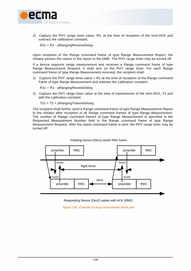
2) Capture the PHY range timer value, R2, at the time of reception of the Imm-ACK andsubtract the calibration constant:
R2c = R2 - pRangingReceiveDelay.
Upon reception of the Range command frame of type Range Measurement Report, theinitiator passes the values in the report to the DME. The PHY range timer may be turned off.
If a device supports range measurement and receives a Range command frame of typeRange Measurement Request, it shall turn on the PHY range timer. For each Rangecommand frame of type Range Measurement received, the recipient shall:
1) Capture the PHY range timer value = R1 at the time of reception of the Range commandframe of type Range Measurement and subtract the calibration constant:
R1c = R1 - pRangingReceiveDelay.
2) Capture the PHY range timer value at the time of transmission of the Imm-ACK, T2 andadd the calibration constant:
T2c = T2 + pRangingTransmitDelay.
The recipient shall further send a Range command frame of type Range Measurement Reportto the initiator after reception of all Range command frames of type Range Measurement.The number of Range command frames of type Range Measurement is specified in theRequested Measurement Number field in the Range command frame of type RangeMeasurement Request. After the report command frame is sent, the PHY range timer may beturned off.
Initiating Device (Dev1) sends RM1 frame
preamble
preamble preamble
Responding Device (Dev2) replies with ACK (RM2)
SIFS
preambleRM1
RM1 RM2
RM2
flight times
Sest[0]Sest[0]
Sest[0] Sest[0]
Figure 109 - Example of range measurement frame pair
- 238 -

DEV1DME
DEV1MAC
DEV1PHY
DEV2PHY
DEV2MAC
RangeMeasurement
set request
Send RRQ
turn on range timer
IMM-ACKto RRQ
turn on range timer
Send RM1to DEV2
Read T1 Read R1IMM-ACKto RM1
Send RM1
Read R2 Read T2
Compute:T1c = T1+TRDR2c = R2-RRD
Compute:R1c = R1-RRDT2c = T2-TRD
Send RMR
IMM-ACKto RMR
turn off range timer
turn off range timer
RangeMeasurement
set confirm
Figure 110 - Single pair range measurement transaction
- 239 -
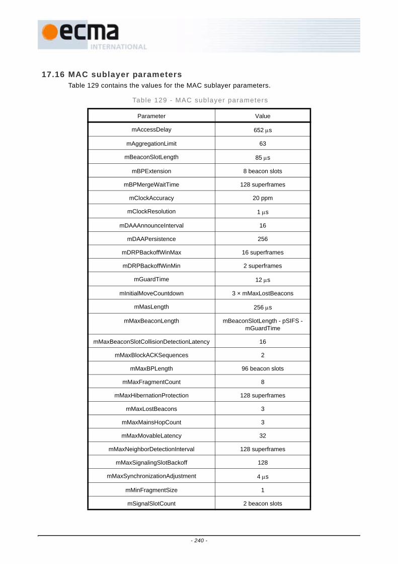
17.16 MAC sublayer parametersTable 129 contains the values for the MAC sublayer parameters.
Table 129 - MAC sublayer parameters
Parameter Value
mAccessDelay 652 μs
mAggregationLimit 63
mBeaconSlotLength 85 μs
mBPExtension 8 beacon slots
mBPMergeWaitTime 128 superframes
mClockAccuracy 20 ppm
mClockResolution 1 μs
mDAAAnnounceInterval 16
mDAAPersistence 256
mDRPBackoffWinMax 16 superframes
mDRPBackoffWinMin 2 superframes
mGuardTime 12 μs
mInitialMoveCountdown 3 × mMaxLostBeacons
mMasLength 256 μs
mMaxBeaconLength mBeaconSlotLength - pSIFS - mGuardTime
mMaxBeaconSlotCollisionDetectionLatency 16
mMaxBlockACKSequences 2
mMaxBPLength 96 beacon slots
mMaxFragmentCount 8
mMaxHibernationProtection 128 superframes
mMaxLostBeacons 3
mMaxMainsHopCount 3
mMaxMovableLatency 32
mMaxNeighborDetectionInterval 128 superframes
mMaxSignalingSlotBackoff 128
mMaxSynchronizationAdjustment 4 μs
mMinFragmentSize 1
mSignalSlotCount 2 beacon slots
- 240 -

Table 130 contains the values of the PHY dependent parameters used by the MAC sublayerfor the PHY.
18 Security
This Clause specifies available security mechanisms. 18.1 reviews these security mechanisms.18.2 defines security modes that govern the security operation of devices. 18.3 specifies the
mSuperframeLength 256 × mMasLength
mCWMin[AC_BK]
mCWMin[AC_BE]
mCWMin[AC_VI]
mCWMin[AC_VO]
15
15
7
3
mCWMax[AC_BK]
mCWMax[AC_BE]
mCWMax[AC_VI]
mCWMax[AC_VO]
1 023
1 023
511
255
mAIFSN[AC_BK]
mAIFSN[AC_BE]
mAIFSN[AC_VI]
mAIFSN[AC_VO]
7
4
2
1
mTXOPLimit[AC_BK]
mTXOPLimit[AC_BE]
mTXOPLimit[AC_VI]
mTXOPLimit[AC_VO]
512 μs
512 μs
1 024 μs
256 μs
Table 130 - PHY-dependent MAC sublayer parameters for the PHY
Parameter Value
pBeaconTransmitRate 53,3 Mbps
pCCADetectTime 5,625 μs
pClockAccuracy 20 ppm
pMaxFramePayloadSize 4 095 octets
pMIFS 1,875 μs
pRangingReceiveDelay Implementation-dependent
pRangingTransmitDelay Implementation-dependent
pSIFS 10 μs
pSlotTime 9 μs
Table 129 - MAC sublayer parameters (concluded)
Parameter Value
- 241 -

4-way handshake procedure for two devices to establish pair-wise temporal keys (PTKs) and asecure relationship. This Clause also describes how a device may solicit or distribute grouptemporal keys (GTKs) within a secure relationship. 18.4 describes the procedures for framereception and replay prevention. 18.5 provides the parameters needed in applying the AES-128CCM cryptography to compute the message integrity code (MIC) and encrypt the securepayload for secure frames.
18.1 Security mechanismsThe security mechanisms specified in this Standard control the security operation of devicesby setting appropriate security modes. They allow devices to authenticate each other, toderive PTKs, and to establish secure relationships. They also enable devices to solicit ordistribute GTKs within established secure relationships. In addition, the security mechanismsprovide replay attack prevention measures through the use of secure frame counters (SFCs)and replay counters. The security mechanisms specify the parameters needed in applyingthe AES-128 CCM to protect the privacy and integrity of unicast and broadcast/multicasttraffic using PTKs and GTKs, respectively. Privacy is protected by encrypting the securepayload, while integrity is protected by including a MIC.
Two devices use a shared master key to establish a secure relationship. The establishmentand management of master keys are additional security facilities that need to be providedoutside the MAC sublayer.
18.1.1 Security operationSecurity modes are defined to control the level of security required of a device in itscommunications with other devices. Three security modes are provided. Mode 0 allows adevice to communicate without security protection. Mode 1 allows a device to use bothsecure and non-secure frames for data exchanges. Mode 2 restricts a device to usesecurity facilities in transmitting and receiving certain frames.
A device announces its selected security mode in the Beacon Parameters field in itsbeacons.
18.1.2 4-way handshakeThe 4-way handshake mechanism enables two devices to use a shared master key toauthenticate the identity of each other and to establish a new PTK for protecting certainframes exchanged between the two devices. By way of a successful 4-way handshake, thetwo devices establish a secure relationship with each other.
A device initiates a 4-way handshake with another device only if it has determined that itshares a master key with that device. The master key is not exposed in the 4-wayhandshake; it is specified by a master key identifier (MKID).
18.1.3 Key transportTwo devices establish a new PTK via a 4-way handshake. The PTK is derived from ashared master key and two new random numbers generated by the two devices. A PTK isnever transmitted directly in any frame, encrypted or not.
Two devices, after establishing a secure relationship via a successful 4-way handshake,distribute their respective GTKs for protecting their broadcast traffic to each other, ifapplicable. Additionally, a device may distribute GTKs for protecting certain multicast trafficaddressed to those devices with which the device has a valid secure relationship. A devicemay also request, or solicit, GTKs used to protect multicast traffic from the multicastsource devices.
A GTK is sent in encrypted form.
- 242 -
18.1.4 Freshness protectionFreshness protection insures that no parties can successfully replay previously capturedmessages as an attack. This Standard defines secure frame counters and replay counterson a per-temporal key basis to provide freshness protection.
18.1.5 Data encryptionData encryption uses a symmetric cipher to protect data from access by parties notpossessing the encryption key. This key is a PTK for unicast traffic transmitted betweentwo devices and a GTK for broadcast/multicast traffic transmitted from a sender to a groupof recipients.
AES-128 counter mode is used for data encryption in this Standard.
18.1.6 Frame integrity protectionFrames are protected from modification by other parties by message authentication usinga MIC. The MIC also provides assurance that the sender of the frame possesses thecorrect temporal key. This key is shared among a group of devices or only between twodevices. The MIC is a cryptographic checksum of the message to be protected.
AES-128 cipher block chaining - message authentication code (CBC-MAC) is used for MICcalculation in this Standard.
18.2 Security modesThe security mode indicates whether a device is permitted or required to establish a securerelationship with another device for data communications.
Two devices establish a secure relationship by a 4-way handshake based on a shared masterkey as described in 18.3.
Once two devices establish a secure relationship, they shall use secure frames for frametransfers between them as specified in Table 131 and Table 132. Either device shall discard areceived frame from the other device if the frame is required to be a secure frame but wastransmitted as a non-secure frame.
Data and aggregated data frames shall be transmitted using the temporal key specified bythe TKID passed through the MAC SAP along with the corresponding MSDU. Command andcontrol frames, when transmitted as secure frames in a secure relationship, shall employ atemporal key currently possessed in that secure relationship.
- 243 -

In Table 131, "N" indicates a non-secure frame, and "S" indicates a secure frame.
Table 131 - Frame protect ion in a secure relat ionship
Frame type or subtype Frame protection Meaning
Beacon frame N Beacon frames shall be sent as non-secure frames.
Imm-ACK control frame N Imm-ACK frames shall be sent as non-secure frames.
B-ACK control frame N B-ACK frames shall be sent as non-secure frames.
RTS control frame N RTS frames shall be sent as non-secure frames.
CTS control frame N CTS frames shall be sent as non-secure frames.
UDA control frame N UDA frames shall be sent as non-secure frames.
UDR control frame N UDR frames shall be sent as non-secure frames.
Application-specific control frame
N, S Application-specific control frames may be sent as secure or non-secure frames.
DRP Reservation Request command frame
N, S DRP Reservation Request frames may be sent as secure or non-secure frames.
DRP Reservation Response command frame
N,S DRP Reservation Response frames may be sent as secure or non-secure frames.
Probe command frame N, S Probe frames may be sent as secure or non-secure frames.
PTK command frame N, S PTK frames may be sent as secure or non-secure frames.
GTK command frame S GTK frames shall be sent as secure frames.
Range Measurement command frame
N, S Range Measurement frames may be sent as secure or non-secure frames.
Probe command frame N, S Probe frames may be sent as secure or non-secure frames.
Application-specific command frame
N, S Application-specific command frames may be sent as secure or non-secure frames.
Data frame S Data frames shall be sent as secure frames.
Aggregated data frame S Aggregated data frames shall be sent as secure frames.
- 244 -

Table 132 specifies the values of the Encryption Offset (EO) field in secure frames
18.2.1 Security mode 0A device operating in security mode 0 shall use non-secure frames to communicate withother devices. Such a device shall not establish a secure relationship with any otherdevice.
If a device operating in this mode receives a secure frame, the MAC sublayer shall discardthe frame.
18.2.2 Security mode 1A device operating in security mode 1 shall use non-secure frames to communicate withdevices operating in security mode 0. The device shall also use non-secure frames tocommunicate with devices operating in security mode 1 with which it does not have securerelationships. The device shall use secure frames according to Table 131 and Table 132 tocommunicate with another device operating in security mode 1 with which it has a securerelationship. It shall not establish secure relationships with other devices unless thosedevices are also operating in security mode 1.
A device operating in security mode 1 may or may not respond to command framesreceived from other devices with which it does not have a secure relationship.
If a device operating in security mode 1 receives a secure frame from a device with whichit does not have a secure relationship, the MAC sublayer shall discard the frame.
If a device operating in mode 1 receives a non-secure frame from a device with which ithas a secure relationship, but the frame is required to be a secure frame per Table 131, theMAC sublayer shall discard the frame.
18.2.3 Security mode 2A device operating in security mode 2 shall not establish a secure relationship with devicesoperating in either security mode 0 or security mode 1. The device shall use secure framesbased on Table 131 and Table 132 to communicate with another device operating insecurity mode 2 and having a secure relationship with it. A device operating in security
Table 132 - EO values in secure f rames
Frame type or subtype EO value
Application-specific control frame Application defined
DRP Reservation Request command frame
Length of Secure Payload
DRP Reservation Response command frame
Length of Secure Payload
PTK command frame 0
GTK command frame 0
Range Measurement command frame Length of Secure Payload
Probe command frame Variable
Application-specific command frame Application defined
Data frame Variable
Aggregated data frame Length of (Aggregation Header + Aggregation Header Pad octets)
- 245 -

mode 2 shall establish a secure relationship with another device operating in the samesecurity mode by a 4-way handshake prior to data exchanges.
If a device operating in mode 2 receives a secure frame from a device with which it doesnot have a secure relationship, the MAC sublayer shall discard the frame.
If a device operating in mode 2 receives a non-secure frame that is required to have frameprotection per Table 131, regardless of whether the device has a secure relationship withthe device transmitting the frame, the MAC sublayer shall discard the frame.
18.3 Temporal keysTwo devices establish a secure relationship based on a shared master key by employing a 4-way handshake to derive a PTK as described in this Clause. They may establish a PTK foreach master key they share. Two devices have a secure relationship as long as they possessa currently installed PTK. A device's DevAddr is part of the information used in deriving aPTK. Once a PTK is established, it shall not be changed due to a change in the device'sDevAddr.
A device solicits a GTK from, or distributes a GTK to, another device sharing a PTK as alsodescribed in this Clause.
Master keys are identified by MKIDs. A device is not required to include an MKID IE in itsbeacon, nor is it required to advertise every MKID it possesses in the MKID IE included in itsbeacon. It may advertise some or all of the MKIDs it possesses in an MKID IE in its beacon.A device may probe another device for the MKIDs possessed by that device by addressing anappropriate Probe IE in a beacon or Probe command to that device. If a device responds to aProbe request for MKIDs, it shall report all the MKIDs it possesses.
18.3.1 Mutual authentication and PTK derivationThis Standard uses a 4-way handshake to provide mutual authentication and PTKgeneration for two devices sharing a master key. To perform a 4-way handshake, the twodevices assume the roles of "initiator" and "responder", respectively. A 4-way handshakeconsists of four messages, called message 1, message 2, message 3, and message 4, thatare sent back and forth between the two devices. The device sending message 1 becomesthe initiator. The other device becomes the responder.
18.3.1.1 4-way handshake message 1The initiator shall begin a 4-way handshake by composing and sending message 1 in aPTK command to the responder. In this command, the initiator shall specify the MKID foruse in the 4-way handshake, propose a TKID for the PTK to be derived, and include aunique 128-bit cryptographic random number, I-Nonce. The proposed TKID shall bedifferent from any TKID currently installed in the initiator's local MAC sublayer or beingused in an in-progress 4-way handshake involving this initiator device. The I-Nonce shallbe generated anew each time the initiator starts a new 4-way handshake.
On reception of message 1, the responder shall verify that the requested TKID is unique(i.e., not currently installed for an active temporal key or requested by an in-process 4-way handshake exchange). The responder shall perform the following steps:
1. Generate a new 128-bit cryptographic random number, R-Nonce.
2. Derive the PTK and KCK as specified in 18.3.4.
3. Construct and send message 2 in a PTK command.
18.3.1.2 4-way handshake message 2The responder shall send message 2 to the initiator as specified in 18.3.1.1. In thiscommand, the responder shall include an appropriate Status Code, the newly generatedR-Nonce, and the PTK MIC value computed for the message using the newly derived
- 246 -

KCK according to 18.3.5. If the proposed TKID in message 1 is not unique, theresponder shall so indicate in the Status Code.
On reception of message 2, the initiator shall perform the following steps:
1. Derive the PTK and KCK as specified in 18.3.4.
2. Recalculate the PTK MIC for the received message using the KCK according to18.3.5. If the recalculated PTK MIC does not match the PTK MIC field from thismessage, discard and disregard message 2 and abort the 4-way handshake.Otherwise, consider this message a proof that the responder holds the correctmaster key, and proceed to the next step.
3. Check the Status Code returned in the received message. If the Status Codeindicates an abortion of the 4-way handshake by the responder, stop the 4-wayhandshake as well. If the Status Code indicates a conflict of the proposed TKID atthe responder, restart the 4-way handshake with a different TKID. If the Status Codeindicates a normal status, proceed to the next step.
4. Construct and send message 3 in a PTK command.
18.3.1.3 4-way handshake message 3The initiator shall send message 3 to the responder as specified in 18.3.1.2. In thiscommand, the initiator shall include the same I-Nonce as contained in message 1 and aPTK MIC computed for this message using the newly derived KCK according to 18.3.5.
On reception of message 3, the responder shall perform the following steps:
1. Verify the PTK MIC for this message using the KCK according to 18.3.5. If thecalculated PTK MIC does not match the PTK MIC field from this message, discardand disregard message 3 and abort the 4-way handshake. Otherwise, consider thismessage a proof that the initiator holds the correct master key, and proceed to thenext two steps.
2. Construct and send message 4 in a PTK command.
3. Save the PTK for future use with this secure relationship.
18.3.1.4 4-way handshake message 4The responder shall send message 4 to the initiator as specified in 18.3.1.3. In thiscommand, the responder shall include the same R-Nonce as contained in message 2and a PTK MIC computed for this message using the KCK according to 18.3.5.
On reception of message 4, the initiator shall perform the following step:
1. Verify the PTK MIC for this message using the KCK according to 18.3.5. If thecalculated PTK MIC does not match the PTK MIC field from this message, discardand disregard message 4 and abort the 4-way handshake. Otherwise, save the PTKfor future use with this secure relationship.
18.3.2 GTK exchangeUpon successful completion of a 4-way handshake and installation of the resulting PTK,the initiator and responder each shall use GTK command frames (with Message Numberset to 1) to distribute their respective GTKs for broadcast traffic to each other. Each mayalso use a GTK command to distribute a GTK for protecting certain multicast traffic to anintended recipient with which it holds a valid PTK.
On reception of a valid GTK command frame marked as Message Number 1, a device shallverify that the GTKID is a unique TKID. The device shall then respond with a GTKcommand frame with Message Number set to 2 and Status Code set to the appropriatevalue.
- 247 -

A recipient may request a GTK for certain multicast traffic in the form of a GTK command(with Message Number set to 0) from the source device if it holds a valid PTK with thesource.
On reception of a valid GTK command marked as Message Number 0, the multicast sourcedevice shall respond with a GTK command marked as Message Number 1, which may ormay not contain the requested GTK. The requesting device, upon receiving this GTKcommand and verifying the uniqueness of the proposed TKID, shall further return a GTKcommand with Message Number set to 2 and Status Code set to the appropriate value.
A source device distributing a GTK shall check the Status Code indicated in the returnedGTK command (Message Number set to 2). If the Status Code indicates a conflict of theproposed TKID at the recipient device, the source device shall propose a new TKID and re-distribute the GTK to the recipient. After receiving a returned GTK command from therecipient with the Status Code indicating a normal status, the source device shall use thenew TKID to re-distribute the GTK to each of the devices to which it has previouslydistributed the GTK and with which it maintains a secure relationship.
A GTK shall be a 128-bit cryptographic-grade random number. A fresh GTK shall begenerated when the distributing device establishes a new group relationship. 18.3.6provides an example means of generating a fresh GTK.
18.3.3 Pseudo-random function (PRF) definit ionA PRF is used in several places in the security specification. Depending on the use, thePRF may need to output values of 64 bits, 128 bits, and 256 bits. This Clause defines threePRF variants:
• PRF-64, which outputs 64 bits,
• PRF-128, which outputs 128 bits, and
• PRF-256, which outputs 256 bits.
In the following, K denotes a 128-bit symmetric key, N denotes a 13-octet nonce value, Adenotes a unique 14-octet ASCII text label for each different use of the PRF, B denotes theinput data stream, Blen specifies the length of this data stream, and || denotesconcatenation. Blocks are each 16 octets long, and are defined as inputs to the AES-128CCM for the MIC generation as specified in 18.5.
CCM-MAC-FUNCTION(K, N, A, B, Blen)
begin
Form authentication block B_0 from flags = 0x59, N, and l(m) = 0
Form authentication block B_1 from l(a) = 14 + Blen and A
Form additional authentication blocks from B
(with last block zero padded as needed)
Form encryption block A_0 from flags = 0x01, N, and Counter_0 = 0
R ← MIC (K, B_0, B_1, ..., A_0)
return R
PRF(K, N, A, B, Blen, Len)
for i ← 1 to (Len + 63)/64 do
R ← R || CCM-MAC-FUNCTION(K, N, A, B, Blen)
- 248 -

N ← N + 1
return L(R, 0, Len) = Len most-significant bits of R
PRF-64(K, N, A, B, Blen) = PRF(K, N, A, B, Blen, 64)
PRF-128(K, N, A, B, Blen) = PRF(K, N, A, B, Blen, 128)
PRF-256(K, N, A, B, Blen) = PRF(K, N, A, B, Blen, 256)
18.3.4 PTK and KCK derivationPRF-256 shall be employed to generate the PTK and KCK associated with a 4-wayhandshake as used in 18.3.1 based on the following parameters as defined in Table 133.
K - The PMK
N - B12-11= InitiatorDevAddr, B10-9= ResponderDevAddr, B8-6 = PTKID, B5-0 = zero
A - "Pair-wise keys"
B - I-Nonce || R-Nonce
Blen - 32
The PRF-256 is called with these parameters to compute a 256-bit key stream:
KeyStream ← PRF-256(K, N, A, B, Blen)
This key stream is then split to form the desired PTK and KCK. The least-significant 16octets of KeyStream become the KCK while the most-significant 16 octets become thePTK, as defined in Table 134.
Table 133 - PTK and KCK generat ion parameters
Name Size (octets) Description
InitiatorDevAddr 2 DevAddr of device with role of initiator
ResponderDevAddr 2 DevAddr of device with role of responder
I-Nonce 16 Random number selected by initiator (in message 1)
R- Nonce 16 Random number selected by responder (in message 2)
PTKID 3 Negotiated TKID value for the PTK to be derived (in message 1)
PMK 16 A pre-shared pair-wise master key identified by the MKID (in message 1)
Table 134 - KCK and PTK Source
Key Source
KCK KeyStream octets 0 through 15
PTK KeyStream octets 16 through 31
- 249 -

18.3.5 PTK MIC generationThe 4-way handshake uses an "out-of-band MIC" calculation for the PTK MIC field inhandshake messages 2-4. PRF-64 shall be used to provide the PTK MIC calculation. ThePRF-64 parameters shall be defined as follows based on Table 133:
K - The KCK
N - B12-11 = InitiatorDevAddr, B10-9 = ResponderDevAddr, B8-6 = PTKID, B5-0 = zero
A - "out-of-bandMIC"
B - Fields from Message Number to I-Nonce/R-Nonce contained in the PTK command
Blen - Length in octets of B = 48
PTK MIC ← PRF-64(K, N, A, B, Blen)
18.3.6 Random number generationTo implement the cryptographic mechanisms outlined in this Standard, devices need togenerate cryptographic grade random numbers. RFC 4086 [4] gives a detailed explanationof the notion of cryptographic grade random numbers and provides guidance for collectingsuitable randomness. It recommends collecting random samples from multiple sourcesfollowed by conditioning with PRF. This method can provide a means for animplementation to create an unpredictable seed for a pseudo-random generation function.The example below shows how to distill such a seed using random samples and PRF-128.
LoopCounter = 0
Nonce = 0
while LoopCounter < 32 begin
result = PRF-128(0, Nonce, "InitRandomSeed", DevAddr || Time || result ||LoopCounter, dataLen)
Nonce ← Nonce + 1
result ← result || <randomness samples>
end
GlobalSeed = PRF-128(0, Nonce, "InitRandomSeed", DevAddr || Time || result ||LoopCounter, dataLen)
Once the seed has been distilled, it can be used as a key for further random numbergeneration. The 4-way handshake requires each party to supply a 128-bit random number.This number can be generated using the seed and PRF-128.
GenerateRandomNonce
begin
N = DevAddr || DevAddr || zero
Collect randomness samples
result = PRF-128(Global Seed, N, "Random Numbers", <randomness samples>,length of samples)
return result
18.4 Frame reception steps and replay prevention measuresA recipient device shall carry out the reception steps and replay prevention measures asspecified in this Clause.
- 250 -

18.4.1 Frame receptionThe MAC sublayer shall perform the following validation steps when receiving frames:
1. Validate the FCS. If this validation fails, discard the frame. Otherwise, acknowledgethe received frame using the appropriate acknowledgment rules, and proceed to thenext step.
2. Validate the Secure bit setting in the MAC Header and take the appropriate actionsaccording to its security mode as specified in 18.2. If the frame is not discarded andthe Secure bit is set to ONE, proceed to the next step.
3. Validate the TKID. If the TKID does not identify a currently installed PTK or GTK,discard the frame. Otherwise, proceed to the next step.
4. Validate the MIC using the identified PTK or GTK as specified in 18.5. If this validationfails, discard the frame. Otherwise, proceed to the next step.
5. Detect frame replay as specified in 18.4.2. If replay is detected, discard the frame.Otherwise, update the replay counter that was set up for the PTK or GTK used for thisframe as also specified in 18.4.2, and proceed to the next step.
6. Process the frame as specified in Clause 17, including duplicate frame filtering. If theframe was already received, discard it. Otherwise, proceed to the next step.
7. Decrypt the frame. This step may be taken in parallel with the MIC validation step.
18.4.2 Replay preventionEach transmitting MAC sublayer shall set up a 48-bit SFC and initialize it to zero when atemporal key, PTK or GTK, is installed to it. The MAC sublayer shall increment the SFC byone before transmitting a secure frame - whether a new frame or a retry - that uses thetemporal key, and shall set the SFN in that secure frame to the value of the SFC after theincrement.
Each recipient MAC sublayer shall set up a 48-bit replay counter when a temporal key,PTK or GTK, is installed to it. The MAC sublayer shall initialize the replay counter to zerofor an installed PTK, and to the GTK SFC for an installed GTK which was contained in theGTK command distributing the GTK.
Upon receipt of a secure frame with valid FCS and MIC, the recipient shall perform replayattack detection and protection as follows:
The recipient shall compare the SFN extracted from the received frame with the reading ofthe replay counter for the temporal key used by the frame. If the extracted SFN is smallerthan or equal to the replay counter reading, the recipient MAC sublayer shall discard theframe. Otherwise, the recipient shall set the corresponding replay counter to the receivedSFN.
The recipient shall insure that the frame passes FCS validation, replay prevention, andMIC verification before using the SFN to update its replay counter.
18.4.3 Implications on GTKsBecause a recipient maintains only one replay counter per installed temporal key, thatrecipient can receive traffic from only one source using a given temporal key. A schemethat allows multiple source devices to use the same GTK will result in frames sent fromsome of those sources being seen as replay attacks. To avoid this problem, each sourcedevice in a group is required to distribute a unique GTK to the recipients in the group.
18.5 AES-128 CCM InputsAES-128 CCM provides confidentiality, authentication, and integrity for secure framesdefined in this Standard. This Clause specifies the various fields required for AES-128 CCMoperation.
- 251 -

18.5.1 OverviewAES, the Advanced Encryption Standard, is specified in FIPS PUB 197. AES-128 defines asymmetric block cipher that processes 128-bit data blocks using 128-bit cipher keys. CCM,counter with CBC-MAC, is specified in RFC 3610. CCM employs counter mode forencryption and cipher block chaining for authentication. AES-128 CCM combines AES-128with CCM to encrypt and authenticate messages.
Encryption is done on part or all of the Secure Payload, while authentication is provided bya message integrity code (MIC) that is included in each secure frame. MIC also protectsthe integrity of the MAC Header and Frame Payload in a secure frame.
CCM has two input parameters - M (number of octets in authentication field) and L (numberof octets in length field). For this Standard, M = 8 and L = 2.
CCM requires the use of a temporal key and a unique Nonce for each transmitted frame tobe protected. The SFN is combined with frame addressing and temporal key identificationinformation to provide a unique Nonce for every secure frame. Since every frameprotection with a key requires a unique Nonce, temporal keys have a known lifetime. Eachtemporal key can be used to protect up to n frames, where n is the maximum value of theSFN. All security guarantees are void if a nonce value is used more than once with thesame temporal key.
In the following figures in this Clause defining the format of Nonce and CCM blocks, themost-significant octet is represented to the left of the other octets.
18.5.2 NonceThe CCM Nonce is a 13-octet field, consisting of the 2-octet SrcAddr, 2-octet DestAddr,3-octet TKID, and 6-octet SFN for the current frame. The Nonce is used as a component ofauthentication block B_0, an input to CBC-MAC. It is also used as a component of inputblock A_i for CCM encryption. It provides the uniqueness that CCM requires for eachinstance of authentication/encryption. The CCM Nonce shall be formatted as defined inFigure 111. In this figure, each component of the Nonce is represented with the most-significant octet on the left and the least-significant octet on the right.
18.5.3 CCM blocksThe CCM authentication blocks shall be formatted as defined in Figure 112 and furtherdescribed below.
octets: 2 2 3 6
SrcAddr DestAddr TKID SFN
Figure 111 - Nonce input to the CCM algorithm
- 252 -

18.5.3.1 Authentication block B_0Authentication block B_0 is the first input block to the CBC-MAC algorithm. It shall beformatted as defined in Figure 113. The component l(m) is represented with the most-significant octet on the left and the least-significant octet on the right. The Noncecomponent is represented with the least-significant octet on the left and the most-significant octet on the right.
18.5.3.2 Authentication block B_1Authentication block B_1 is the second input block to the CBC-MAC algorithm. It shall beformatted as defined in Figure 114. In this block, the l(a) component is represented withthe most-significant octet on the left and the least-significant octet on the right. The EOand MAC Header components are represented with the first octet transmitted into thewireless medium on the left and the last transmitted octet on the right.
18.5.3.3 Authentication blocks B_2, …, B_NAuthentication blocks B_2, …, B_(M-1) and B_M, …, B_N, if any, are additional inputblocks to the CBC-MAC algorithm. They shall be formatted as defined in Figure 115.They are formed by breaking the Secure Payload portion not to be encrypted into16-octet blocks and the Secure Payload portion to be encrypted into 16-octet blocks.The last block constructed from the Secure Payload portion not to be encrypted ispadded with zero values as needed to insure 16-octet block length. Likewise, the lastblock constructed from the Secure Payload portion to be encrypted is padded with zero
octets: 1 13 2 2 10 2 1 1 EO 0-15 P – EO 0-15
Flags ( = 0x59)
Nonce Encrypted data length l(m) = P –
EO
Additional authenticated data length l(a) = 14 +
EO
MAC Header
Encryption Offset (EO)
Security Reserved
0 Secure Payload
portion not to be
encrypted
Zero padding
Secure Payload portion to
be encrypted
Zero padding
B_0 B_1 B_2, …, B_(M-1) B_M, …, B_N
Figure 112 - Input to CCM authentication blocks
octets: 1 13 2
Flags = 0x59 Nonce l(m)
Figure 113 - Format of authentication block B_0
octets: 2 10 2 1 1
l(a) MAC Header EO Security Reserved 0
Figure 114 - Format of authentication block B_1
- 253 -

values as needed to insure 16-octet block length. The padding octets are not transmittedonto the wireless medium.
In each of the blocks B_2, …, B_(M-1) or B_M, …, B_N, the Secure Payload portion notto be, or to be, encrypted shall be represented with the earliest octet transmitted into thewireless medium on the left and the latest transmitted octet on the right. When needed,B_(M-1) and B_N are padded with zeros to the right.
18.5.3.4 Encryption blocks A_0, A_1, …, A_mCCM uses encryption blocks A_0, A_1, …, A_m to generate key stream blocks that areused to encrypt the CBC-MAC and the Secure Payload portion to be encrypted. Theseblocks shall be formed as defined in Figure 116. In this figure, Counter i is a 2-octetmonotonically incrementing counter that shall be initialized to 0 for each secure frame. Itshall be incremented by one for each successive encryption block. The Counter icomponent of A_i shall be represented with the most-significant octet on the left and theleast-significant octet on the right. The Nonce component shall be represented with theleast-significant octet on the left and the most-significant octet on the right.
octets: EO 0-15 P – EO 0-15
Secure Payload portion not to be
encrypted
Zero padding
Secure Payload portion to be
encrypted
Zero padding
B_2, …, B_(M-1) B_M, …, B_N
Figure 115 - Format of authentication blocks beginning from B_2
octets: 1 13 2
Flags = 0x01 Nonce Counter i
Figure 116 - Format of A_i blocks
- 254 -

Annex A(normative)
MUX sublayer
The MUX sublayer is the MAC client as depicted in Figure 31 and routes data between the MAC sublayer andMUX clients.
A.1 MUX service
The MUX sublayer is expressed in terms of the MUX SAP, the MUX service, and the MUX client.Each MUX client is associated with a unique protocol. Service data units presented at the MUXSAP by the MUX client are therefore associated with that protocol.
The protocol is encoded in a MUX header as either:
• A protocol identifier and an OUI; or
• An IEEE Ethertype value [H2].
The MUX service adds a MUX header to the MUX service data unit to construct a MUX protocoldata unit. The MUX sublayer makes use of the service provided by the MAC sublayer for thetransfer of its protocol data units.
On receipt of a MUX protocol data unit from the MAC sublayer, the MUX service removes theMUX header and delivers the transported service data unit to the appropriate MUX client basedon the identified protocol.
A.2 MUX protocol data unit format
A MUX protocol data unit consists of a MUX Header and a MUX Payload and is defined inFigure A.1.
The MUX Payload field contains the MUX service data unit that is a payload data unit of theprotocol identified in the MUX Header.
The first two octets of the MUX Header are encoded as unsigned binary values, and aredelivered to the MAC sublayer in order from the octet containing the most-significant bits to theoctet containing the least-significant bits. The octet order for this field is the reverse of that formost fields in this specification.
The MUX Payload is a sequence of octets labelled as MUX Payload[0] through MUX Payload[M-1]. Octets are passed to the MAC sublayer in ascending index-value order.
The MUX Header and MUX Payload together form the payload of the MAC sublayer, whichappears to the MAC as a sequence of octets labelled as payload[0] through payload[P-1], asspecified in 16.2.
octets: 2 or 5 N
MUX Header MUX Payload
Figure A.1 - MUX protocol data unit format
- 255 -

There are three versions of the MUX Header, which are distinguished based on the value of thefirst two octets of the header.
A.2.1 MUX Header - OUI version
The first version has a length of five octets and is defined in Figure A.2.
The Protocol ID field is restricted to values from 0 through 255 and is set to a value thatidentifies a protocol defined by the owner of the OUI specified in the OUI field. The OUI is asequence of 3 octets, labelled as oui[0] through oui[2]. Octets of the OUI are passed to the MACsublayer in ascending index-value order.
A.2.2 MUX Header - reserved version
The second version of the MUX Header has a length of two octets and is defined in Figure A.3.
The protocol ID field has values between 256 and 1 535 as defined in Table A.1.
Table A.1 - Protocol ID in the MUX Header
Value Description
0 - 255 Defined by the OUI owner
256 Protocol ID value for WiMedia Logical Link Control Protocol
257 Protocol ID value for Bluetooth
258 - 1 535 Reserved for future use
octets: 2
Protocol ID
(0x0100 - 0x05FF)
Figure A.3 - Format of second version of MUX Header
octets: 2 3
Protocol ID
(0x0000 - 0x00FF)
OUI
Figure A.2 - Format of first version of MUX Header
- 256 -

A.2.3 MUX Header - Ethernet type version
The third version of the MUX Header has a length of two octets and is defined in Figure A.4.
The Ethernet Type field is restricted to values from 1 536 through 65 535 and is set to the valueof an Ethernet type [H2] identifying a protocol.
octets: 2
Ethernet Type
(0x0600 - 0xFFFF)
Figure A.4 - Format of third version of MUX Header
- 257 -

- 258 -

Annex B(normative)
MAC policies
B.1 Beacon slot selection
When a device selects an initial beacon slot after scanning for beacons as described in 17.2.3,the device shall transmit a beacon only if it selected a slot within mMaxBPLength/2 after theBPST.
B.2 Reservation limits
A reservation consists of a row component and a column component.
Row component: A portion of a reservation that includes an equal number of MASs at the sameoffset(s) within every zone, optionally excluding zone zero, as indicated in the DRP IEs.
Column component: The portion of the reservation that is not a row component.
Rules stated in this Clause apply independently to a device whether it is a reservation owner ora reservation target. They do not apply to DRP IEs with Reservation Type set to Alien BP.
A device may consider contiguous reservation blocks from multiple column components in thesame zone as if they were a single reservation block in a single column component.
A device shall not allocate more channel time than necessary for its optimal operation.
A device shall set the Unsafe bit of the DRP Control field of a DRP IE according to the followingrules:
A) A device shall not identify more than mTotalMASLimit MASs in DRP IEs with the Unsafe bitset to ZERO.
B) A device shall not identify more than Y consecutive MAS in the same zone within a columncomponent in DRP IEs with the Unsafe bit set to ZERO, where Y is a function of the MASnumber within the zone (counting from zero) of the earliest reserved MAS within the set ofconsecutive MASs, as defined in Table B.1.
- 259 -

C) A device shall not set the Unsafe bit to ONE in DRP IEs except to comply with A) or B).
A device shall not include MASs in zone zero in the column component of a reservation.
A device may at any time send a Relinquish Request IE in its beacon where the Target DevAddridentifies a device transmitting its beacon with one or more DRP IEs with the Unsafe bit of theDRP IE Control field set to ONE (unsafe DRP IEs). The device shall not set the Target DevAddrfield to identify a device if that device does not include any unsafe DRP IEs in its beacon,unless forwarding a received Relinquish Request IE to its reservation owner, as specified in17.1.10.19.
The Allocation fields of the Relinquish Request IE should identify MASs in one or more unsafeDRP IEs.
The Reason Code of the Relinquish Request Control field should be set to a valid Reason Codeindicating the reason for requesting the identified MASs.
If a device receives a beacon that contains a Relinquish Request IE with Target DevAddr set toits own DevAddr that identifies MASs it includes in an unsafe DRP IE, it shall:
• Modify its DRP IEs to remove the identified MASs; or
• Modify its DRP IEs such that the Unsafe bit in any DRP IE that includes one or more identifiedMAS is set to ZERO per the previous rules in this Clause.
Table B.1 - Reservat ion block s ize l imi ts
First MAS number Y
0 8
1 7
2 6
3 5
4 4
5 4
6 4
7 4
8 4
9 4
10 4
11 4
12 4
13 3
14 2
15 1
- 260 -

The device shall make this adjustment within mUnsafeReleaseLimit superframes after firstreceiving the Relinquish Request IE.
If a device requests a neighbour to release MASs in an unsafe DRP IE, the device shall notinclude a new unsafe DRP IE in its beacon or change a DRP IE to set the Unsafe bit to ONEuntil mOwnerUnsafeHoldoff has passed.
If a device includes an unsafe DRP IE in its beacon and it receives a Relinquish Request IE thatidentifies MASs included in the DRP IE, it shall not include a new unsafe DRP IE in its beaconor change a DRP IE to set the Unsafe bit to ONE until the neighbour requesting releaseestablishes a new DRP IE or mTargetUnsafeHoldoff has passed.
B.3 PCA reservations
If a device initiates frame transactions in PCA reservations established by its neighbours, itshould also establish PCA reservations that include the MASs it uses. A device shall not initiateframe transactions in more than mTotalMASLimit MASs that are included in DRP IEs with theUnsafe bit set to ZERO and Reservation Type set to PCA included in beacons by the device orany neighbour.
B.4 Reservation locations
As referenced in this Clause, a reservation owner shall select MASs based on a minimumlatency requirement of not less than 4 milliseconds, or on a medium utilization efficiency orpower consumption requirement for a minimum reservation block length.
In the row component of a reservation, the reservation owner shall select reservation blockssuch that the lowest MAS number selected within a zone is maximized, except that thereservation owner is not required to use more than one reservation block per zone.
In the column component of a reservation, the reservation owner shall select reservation blocksthat meet its requirements such that each block is located within the first eight MASs of its zone,if possible. If not possible, the reservation owner shall select reservation blocks that meet itsrequirements and that minimize the highest MAS number selected in any zone.
If multiple potential zone locations meet the previous requirements, the reservation owner shallselect reservation blocks in zones such that the latest used set in the following ordered list ofsets is as early as possible:
[{8}, {4 or 12}, {2, 6, 10, or 14}, {1, 3, 5, 7, 9, 11, 13, or 15}].
If there are multiple possible zone locations that use the same latest set, the reservation ownershould minimize the highest MAS number selected within the zones. The reservation ownershall place each reservation block at the earliest available location within its zone.
If the MASs available for reservation by the reservation owner change, it shall determine if itsreservations would still meet the reservation location rules listed in B.4. If not, the reservationowner shall change its reservations within mCompactionLimit superframes such that they meetthe reservation location rules.
A reservation owner may disregard the reservation location rules for MASs identified in DRPIEs with the Unsafe bit set to ONE according to the Y limit stated in B.2.
B.5 Transmit power control
A device shall support transmit power control and use the lowest possible transmit power withwhich it can maintain its links.
- 261 -

B.6 MAC policies parameters
Table B.2 contains the values for the MAC policies parameters.
Table B.2 - MAC pol ic ies parameters
Parameter Value
mCompactionLimit 32 superframes
mOwnerUnsafeHoldoff 32 superframes
mTargetUnsafeHoldoff 2×mMaxLostBeacons superframes
mTotalMASLimit 112 MASs
mUnsafeReleaseLimit 4 superframes
- 262 -

Annex C(normative)
Specifier ID Assigned numbers
The Specifier ID identifies a company or organization that is responsible for the definition of theapplication-specific control frames, command frames, IEs and Probe IEs. The Specifier ID isrepresented by a 16-bit value that is associated with a company or organization. Use the link athttp://www.ecma-international.org/publications/standards/Ecma-368.htm for the Specifier IDRegister.
Implementors can request their own Specifier ID from the same URL.
These assigned numbers are referred to in 15.6.13, 16.4.7, 16.5.7, 16.8.1 and 16.8.2.
- 263 -

- 264 -
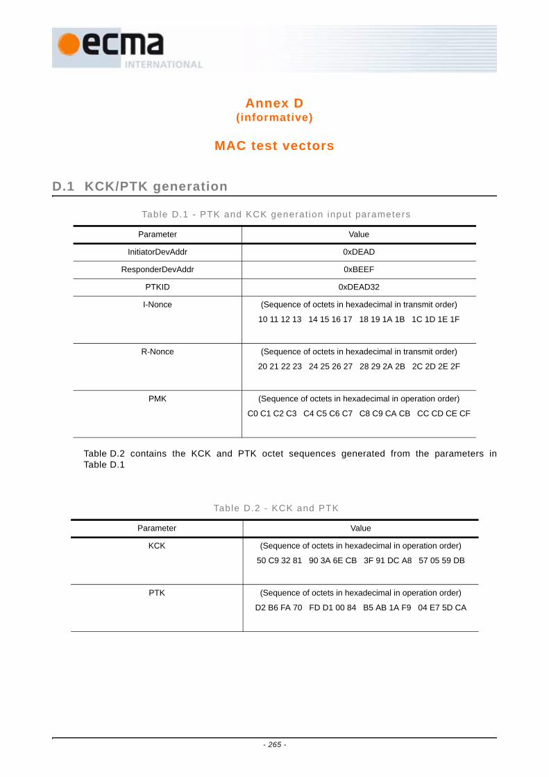
Annex D(informative)
MAC test vectors
D.1 KCK/PTK generation
Table D.2 contains the KCK and PTK octet sequences generated from the parameters inTable D.1
Table D.1 - PTK and KCK generat ion input parameters
Parameter Value
InitiatorDevAddr 0xDEAD
ResponderDevAddr 0xBEEF
PTKID 0xDEAD32
I-Nonce (Sequence of octets in hexadecimal in transmit order)
10 11 12 13 14 15 16 17 18 19 1A 1B 1C 1D 1E 1F
R-Nonce (Sequence of octets in hexadecimal in transmit order)
20 21 22 23 24 25 26 27 28 29 2A 2B 2C 2D 2E 2F
PMK (Sequence of octets in hexadecimal in operation order)
C0 C1 C2 C3 C4 C5 C6 C7 C8 C9 CA CB CC CD CE CF
Table D.2 - KCK and PTK
Parameter Value
KCK (Sequence of octets in hexadecimal in operation order)
50 C9 32 81 90 3A 6E CB 3F 91 DC A8 57 05 59 DB
PTK (Sequence of octets in hexadecimal in operation order)
D2 B6 FA 70 FD D1 00 84 B5 AB 1A F9 04 E7 5D CA
- 265 -
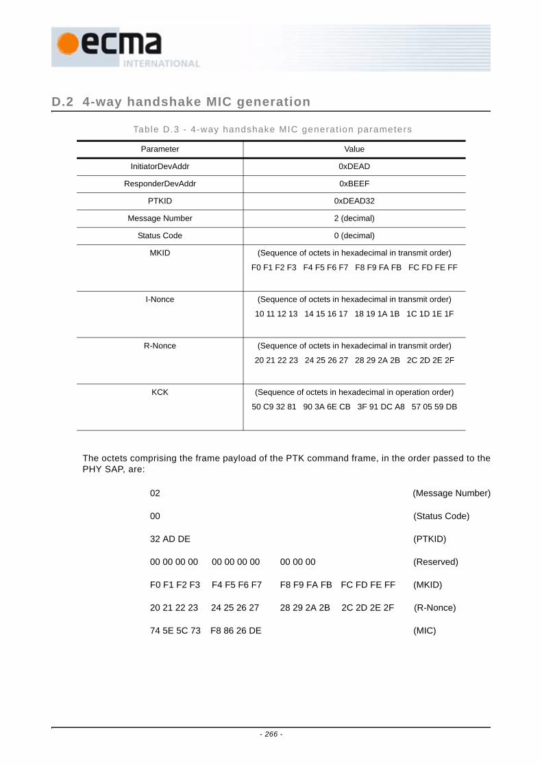
D.2 4-way handshake MIC generation
The octets comprising the frame payload of the PTK command frame, in the order passed to thePHY SAP, are:
02 (Message Number)
00 (Status Code)
32 AD DE (PTKID)
00 00 00 00 00 00 00 00 00 00 00 (Reserved)
F0 F1 F2 F3 F4 F5 F6 F7 F8 F9 FA FB FC FD FE FF (MKID)
20 21 22 23 24 25 26 27 28 29 2A 2B 2C 2D 2E 2F (R-Nonce)
74 5E 5C 73 F8 86 26 DE (MIC)
Table D.3 - 4-way handshake MIC generat ion parameters
Parameter Value
InitiatorDevAddr 0xDEAD
ResponderDevAddr 0xBEEF
PTKID 0xDEAD32
Message Number 2 (decimal)
Status Code 0 (decimal)
MKID (Sequence of octets in hexadecimal in transmit order)
F0 F1 F2 F3 F4 F5 F6 F7 F8 F9 FA FB FC FD FE FF
I-Nonce (Sequence of octets in hexadecimal in transmit order)
10 11 12 13 14 15 16 17 18 19 1A 1B 1C 1D 1E 1F
R-Nonce (Sequence of octets in hexadecimal in transmit order)
20 21 22 23 24 25 26 27 28 29 2A 2B 2C 2D 2E 2F
KCK (Sequence of octets in hexadecimal in operation order)
50 C9 32 81 90 3A 6E CB 3F 91 DC A8 57 05 59 DB
- 266 -

D.3 Non-secure frame example
The octets comprising the MAC Header, the Frame Payload and the FCS are passed to thePHY SAP in the following order:
E0 00 EF BE AD DE 78 01 34 80 (MAC Header)
00 01 02 03 04 05 06 07 08 09 0A 0B (Payload)
0C 0D 0E 0F 10 11 12 13 (Payload)
A4 FF DD 3B (FCS)
Table D.4 - Fie ld values for a non-secure f rame
MAC Fields Value
Frame Control Protocol Version (b2-b0) 0 0x00E0
Secure (b3) 0
ACK Policy (b5-b4) 2 (B-ACK)
Frame Type (b8-b6) 3 (Data)
Frame Subtype / Delivery ID (b12-b9) 0
Retry (b13) 0
Reserved (b15-b14) 0
Dest Addr 0xBEEF
SrcAddr 0xDEAD
Sequence Control
Fragment Number (b2-b0) 0 0x0178
Sequence Number (b13-b3) 47 (decimal)
More Fragments (b14) 0
Reserved (b15) 0
Access Information
Duration (b13-b0) 52 (decimal) 0x8034
More Frames (b14) 0
Access Method (b15) 1
Payload (Sequence of octets in hexadecimal in transmit order)
00 01 02 03 04 05 06 07 08 09 0A 0B
0C 0D 0E 0F 10 11 12 13
- 267 -

D.4 Secure frame example with EO=0
Using the PTK of 1, the octets comprising the MAC Header, the Security Header, the SecurePayload, the MIC and the FCS are passed to the PHY SAP in the following order:
E8 00 EF BE AD DE 78 01 34 80 (MAC Header)
32 AD DE 00 00 00 55 44 33 22 11 00 (Security Header)
BA 68 93 02 EE 86 0E 58 A3 70 74 71 (Secure Payload)
60 E7 B5 95 51 8F F7 B5 (Secure Payload)
2C 89 02 11 F3 B1 37 0B (MIC)
E9 CB AB 31 (FCS)
Table D.5 - Fie ld values for a secure f rame with EO = 0
MAC Fields Value
Frame Control Protocol Version (b2-b0) 0 0x00E8
Secure (b3) 1
ACK Policy (b5-b4) 2 (B-ACK)
Frame Type (b8-b6) 3 (Data)
Frame Subtype / Delivery ID (b12-b9) 0
Retry (b13) 0
Reserved (b15-b14) 0
Dest Addr 0xBEEF
SrcAddr 0xDEAD
Sequence Control
Fragment Number (b2-b0) 0 0x0178
Sequence Number (b13-b3) 47 (decimal)
More Fragments (b14) 0
Reserved (b15) 0
Access Information
Duration (b13-b0) 52 (decimal) 0x8034
More Frames (b14) 0
Access Method (b15) 1
Temporal Key Identifier 0xDEAD32
Encryption Offset 0 0x0000
Secure Frame Number 0x001122334455
Payload (Sequence of octets in hexadecimal in transmit order)
00 01 02 03 04 05 06 07 08 09 0A 0B
0C 0D 0E 0F 10 11 12 13
- 268 -

D.5 Secure frame example with EO = payload length
Using the PTK of 1, the octets comprising the MAC Header, the Security Header, the SecurePayload, the MIC and the FCS are passed to the PHY SAP in the following order:
E8 00 EF BE AD DE 7C 01 34 80 (MAC Header)
32 AD DE 00 14 00 56 44 33 22 11 00 (Security Header)
00 01 02 03 04 05 06 07 08 09 0A 0B (Secure Payload)
0C 0D 0E 0F 10 11 12 13 (Secure Payload)
EE C3 7E 15 3C AD 20 0F (MIC)
EE BF E7 0C (FCS)
Table D.6 - F ie ld values for a secure f rame with EO = payload length
MAC Fields Value
Frame Control
Protocol Version (b2-b0) 0 0x00E8
Secure (b3) 1
ACK Policy (b5-b4) 2 (B-ACK)
Frame Type (b8-b6) 3 (Data)
Frame Subtype / Delivery ID (b12-b9) 0
Retry (b13) 0
Reserved (b15-b14) 0
Dest Addr 0xBEEF
SrcAddr 0xDEAD
Sequence Control
Fragment Number (b2-b0) 4 0x017C
Sequence Number (b13-b3) 47 (decimal)
More Fragments (b14) 0
Reserved (b15) 0
Access Information
Duration (b13-b0) 52 (decimal) 0x8034
More Frames (b14) 0
Access Method (b15) 1
Temporal Key Identifier 0xDEAD32
Encryption Offset 20 (decimal) 0x0014
Secure Frame Number 0x001122334456
Payload (Sequence of octets in hexadecimal in transmit order)
00 01 02 03 04 05 06 07 08 09 0A 0B
0C 0D 0E 0F 10 11 12 13
- 269 -
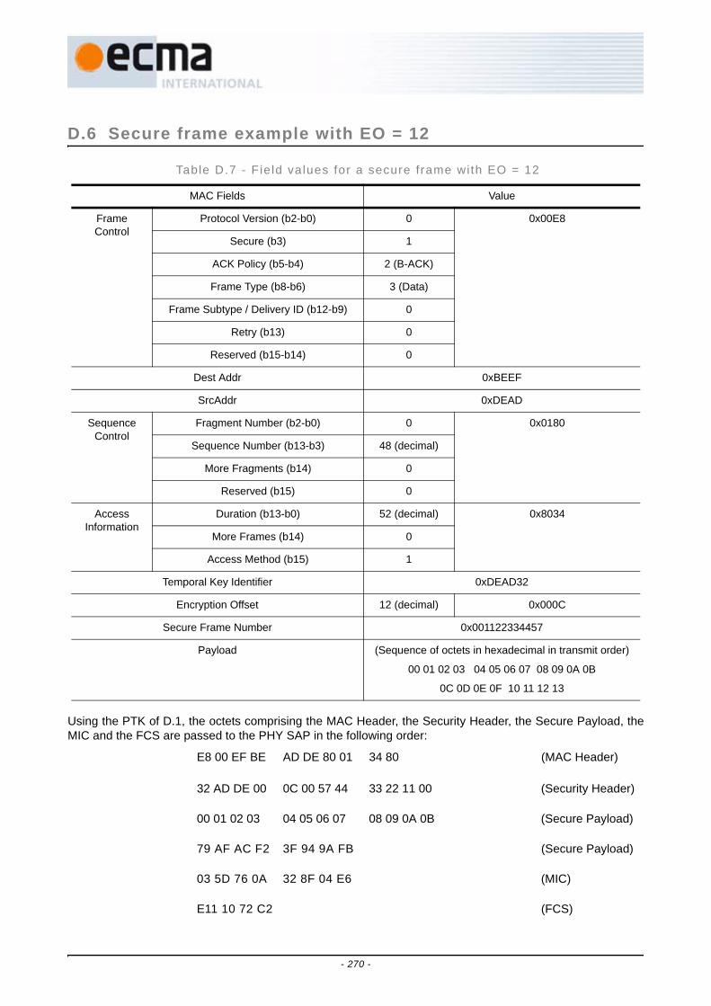
D.6 Secure frame example with EO = 12
Using the PTK of D.1, the octets comprising the MAC Header, the Security Header, the Secure Payload, theMIC and the FCS are passed to the PHY SAP in the following order:
E8 00 EF BE AD DE 80 01 34 80 (MAC Header)
32 AD DE 00 0C 00 57 44 33 22 11 00 (Security Header)
00 01 02 03 04 05 06 07 08 09 0A 0B (Secure Payload)
79 AF AC F2 3F 94 9A FB (Secure Payload)
03 5D 76 0A 32 8F 04 E6 (MIC)
E11 10 72 C2 (FCS)
Table D.7 - Fie ld values for a secure f rame wi th EO = 12
MAC Fields Value
Frame Control
Protocol Version (b2-b0) 0 0x00E8
Secure (b3) 1
ACK Policy (b5-b4) 2 (B-ACK)
Frame Type (b8-b6) 3 (Data)
Frame Subtype / Delivery ID (b12-b9) 0
Retry (b13) 0
Reserved (b15-b14) 0
Dest Addr 0xBEEF
SrcAddr 0xDEAD
Sequence Control
Fragment Number (b2-b0) 0 0x0180
Sequence Number (b13-b3) 48 (decimal)
More Fragments (b14) 0
Reserved (b15) 0
Access Information
Duration (b13-b0) 52 (decimal) 0x8034
More Frames (b14) 0
Access Method (b15) 1
Temporal Key Identifier 0xDEAD32
Encryption Offset 12 (decimal) 0x000C
Secure Frame Number 0x001122334457
Payload (Sequence of octets in hexadecimal in transmit order)
00 01 02 03 04 05 06 07 08 09 0A 0B
0C 0D 0E 0F 10 11 12 13
- 270 -
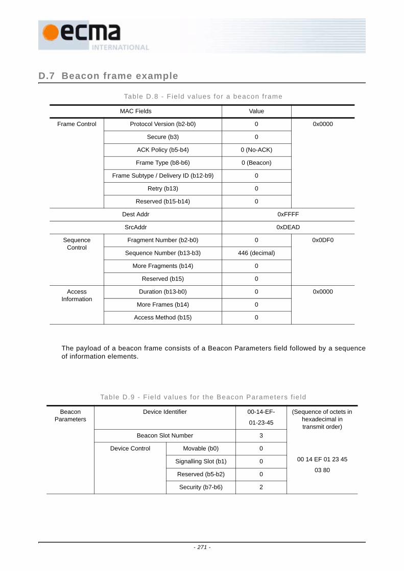
D.7 Beacon frame example
The payload of a beacon frame consists of a Beacon Parameters field followed by a sequenceof information elements.
Table D.8 - Fie ld values for a beacon frame
MAC Fields Value
Frame Control Protocol Version (b2-b0) 0 0x0000
Secure (b3) 0
ACK Policy (b5-b4) 0 (No-ACK)
Frame Type (b8-b6) 0 (Beacon)
Frame Subtype / Delivery ID (b12-b9) 0
Retry (b13) 0
Reserved (b15-b14) 0
Dest Addr 0xFFFF
SrcAddr 0xDEAD
Sequence Control
Fragment Number (b2-b0) 0 0x0DF0
Sequence Number (b13-b3) 446 (decimal)
More Fragments (b14) 0
Reserved (b15) 0
Access Information
Duration (b13-b0) 0 0x0000
More Frames (b14) 0
Access Method (b15) 0
Table D.9 - Fie ld values for the Beacon Parameters f ie ld
Beacon Parameters
Device Identifier 00-14-EF-
01-23-45
(Sequence of octets in hexadecimal in transmit order)
00 14 EF 01 23 45
03 80
Beacon Slot Number 3
Device Control Movable (b0) 0
Signalling Slot (b1) 0
Reserved (b5-b2) 0
Security (b7-b6) 2
- 271 -

Table D.10 - F ie ld values for a BPOIE
BPOIE Element ID 1 (Sequence of octets in hexadecimal in transmit order)
01 0B 0E 10 09 00
00 CE 0A 01 C0 FF
FF
Length 11 (decimal)
BP Length 14 (decimal)
Beacon Slot Info Bitmap
Slot 0: 0
Slot 1: 0
Slot 2: 1
Slot 3: 0
Slot 4: 1
Slot 5: 2
Slots 6-13: 0
Dev Addrs Slot 2: 0x0ACE
Slot 4: 0xC001
Slot 5: 0xFFFF
Table D.11 - Fie ld values for a PCA Avai labi l i ty IE
PCA Availability IE
Element ID 2 (Sequence of octets in hexadecimal in transmit
order)
02 05 01 C0 FF FF 3F
Length 5
Interpretation TIM IE Required (b0) 1
Reserved (b7-b1) 0
PCA Availability Bitmap Slots 0-5: 0
Slots 6-29: 1
Slots 30-255: 0
- 272 -

Table D.12 - Fie ld values for a DRP IE
DRP IE Element ID 9 (Sequence of octets in hexadecimal in
transmit order)
09 08 19 0E CE 0A
FE FF 00 C0
Length 8
DRP Control Reservation Type (b2-b0) 1 (Hard)
Stream Index (b5-b3) 3
Reason Code (b8-b6) 0 (Accepted)
Reservation Status (b9) 1
Owner (b10) 1
Conflict Tiebreaker (b11) 1
Unsafe (b12) 0
Reserved (b15-b13) 0
Target/Owner DevAddr 0x0ACE
DRP Allocation 1 Zone Bitmap Zone 0: 0
Zones 1-15: 1
MAS Bitmap MASs 0-13: 0
MASs 14-15: 1
- 273 -

The octets comprising the MAC Header, the Frame Payload and the FCS are passed to thePHY SAP in the following order:
00 00 FF FF AD DE F0 0D 00 00 (MAC Header)
00 14 EF 01 23 45 03 80 (Payload - Beacon Parameters)
01 0B 0E 10 09 00 00 CE 0A 01 C0 FF (BPOIE)
Table D.13 - Fie ld values for a MAC Capabi l i t ies IE
MAC Capabilities IE
Element ID 12 (decimal) (Sequence of octets in hexadecimal in
transmit order)
0C 02 8B 01
Length 2
MAC Capability Bitmap (octet 0)
PCA (b0) 1
Hard DRP (b1) 1
Soft DRP (b2) 0
Block ACK (b3) 1
Explicit DRP negotiation (b4)
0
Hibernation anchor (b5) 0
Probe (b6) 0
Link feedback (b7) 1
MAC Capability Bitmap (octet 1)
Range measurement (b0) 1
Reserved (b7-b1) 0
Table D.14 - Fie ld values for an Ident i f icat ion IE
MAC Capabilities IE
Element ID 19 (decimal) (Sequence of octets in hexadecimal in
transmit order)
13 13 00 03 00 14
EF 02 0C 4D 00 61
00 63 00 44 00 65
00 76 00
Length 19 (decimal)
Device Information 1 Device Information Type 0 (PHY ID)
Device Information Length 3
Device Information Data 00-14-EF
Device Information 2 Device Information Type 2 (Name String)
Device Information Length 12 (decimal)
Device Information Data "MacDev"
- 274 -

FF
02 05 01 C0 FF FF 3F (PCA Availability IE)
09 08 19 0E CE 0A FE FF 00 C0 (DRP IE)
0C 02 8B 01 (MAC Capabilities IE)
13 13 00 03 00 14 EF 02 0C 4D 00 61 (Identification IE)
00 63 00 44 00 65 00 76 00
4B B5 CA 2F (FCS)
D.8 FCS field example
This Clause provides details of the CRC polynomials in the FCS field calculation described in16.2.7 for the secure frame example in 4.
The frame payload expressed in hexadecimal form, in the order the octets are delivered to thePHY SAP, is:
32 AD DE 00 00 00 55 44 33 22 11 00 BA 68 93 02
EE 86 0E 58 A3 70 74 71 60 E7 B5 95 51 8F F7 B5
2C 89 02 11 F3 B1 37 0B
The coefficients of the terms of the corresponding message polynomial, from the highest-orderto the lowest-order term, are:
0100 1100 1011 0101 0111 1011 0000 0000 … 1100 1111 1000 1101 1110 1100 1101 0000
The message polynomial is:
x318 + x315 + x314 + x311 + x309 + x308 + x306 + x304 + x302 + x301 + x300 + x299 + x297 + x296 + …
+ x31 + x30 + x27 + x26 + x25 + x24 + x23 + x19 + x18 + x16 + x15 + x14 + x13 + x11 + x10 + x7 + x6
+ x4
The CRC calculation results in the following polynomial:
x31 + x28 + x26 + x25 + x24 + x23 + x22 + x20 + x17 + x16 + x15 + x14 + x12 + x10 + x8 + x7 + x3 + x2
The corresponding coefficients are:
1001 0111 1101 0011 1101 0101 1000 1100
The FCS field expressed in hexadecimal form, in the order delivered to the PHY SAP, is:
E9 CB AB 31
- 275 -

- 276 -

Annex E(informative)
Example encoding of a PHY packet
E.1 Introduction
In this Annex, an example test vector for a 40-octet payload transmitted at 200 Mb/s isprovided. Note that in this example some of the intermediate data has been excluded forpurposes of clarity, but the entire packet at the output of the transmitter is shown in E.2.3. Thepacket shall be created as defined in Figure 6, where the Standard PLCP preamble is createdas defined in Figure 7 and Figure 8, the PLCP header is created as defined in Figure 11 andFigure 12, and the PSDU is created as defined in Figure 16 and Figure 17.
E.2 Example device parameters
The device parameters for this example are enumerated in Table E.1.
E.2.1 PHY headerThe PHY header is a non-scrambled 5-octet field as defined in 10.3.1. Based on theparameters listed in Table E.1, the PHY header is described in bits as:
phyHeader = [ 0 0 00 0 1 0 0 (Data Rate)0 0 0 1 0 1 0 0 0 0 0 0 (Length in Octets)0 0 0 1 (Scrambler Seed)0 01 (Burst Mode)0 (Preamble Type)1 0 0 (TX_TFC[T1..T3])1 (BG_LSB)0 00 (TX_TFC[T4])0 0 0 0 0 ], (52)
or, equivalently in octets as 20 28 80 94 00.
Table E.1 - Example PHY Parameters
Parameter Value
Time Frequency Code (TFC) 1
Band Group 1
Preamble Mode Standard
Data Rate 200 Mb/s
Modulation QPSK
Coding Rate 5/8
FDS NO
- 277 -

E.2.1.1 MAC headerThe MAC header is a 10-octet field and for this example is given by:
D3 C2 36 8C 8F 36 0D BB ED BA (53)
The bit representation for the MAC Header is shown in Table E.2.
TDS YES
RATE Bits (R1:R5) 00100
LENGTH 40 octets
SCRAMBLER (S1:S2) 01
Preamble Type (PT) Bit ZERO
Burst Mode (BM) Bit ONE
Table E.1 - Example PHY Parameters (concluded)
Parameter Value
- 278 -
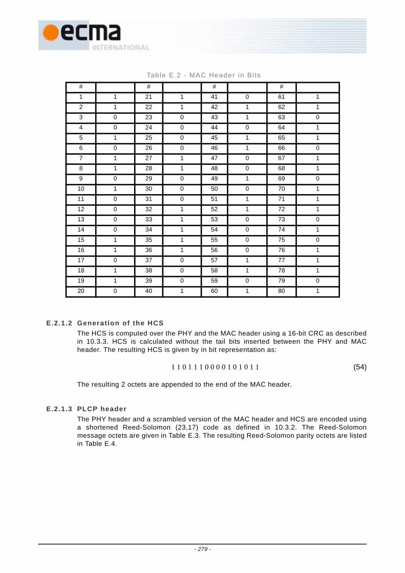
E.2.1.2 Generation of the HCSThe HCS is computed over the PHY and the MAC header using a 16-bit CRC as describedin 10.3.3. HCS is calculated without the tail bits inserted between the PHY and MACheader. The resulting HCS is given by in bit representation as:
1 1 0 1 1 1 0 0 0 0 1 0 1 0 1 1 (54)
The resulting 2 octets are appended to the end of the MAC header.
E.2.1.3 PLCP headerThe PHY header and a scrambled version of the MAC header and HCS are encoded usinga shortened Reed-Solomon (23,17) code as defined in 10.3.2. The Reed-Solomonmessage octets are given in Table E.3. The resulting Reed-Solomon parity octets are listedin Table E.4.
Table E.2 - MAC Header in Bi ts# # # #
1 1 21 1 41 0 61 1
2 1 22 1 42 1 62 1
3 0 23 0 43 1 63 0
4 0 24 0 44 0 64 1
5 1 25 0 45 1 65 1
6 0 26 0 46 1 66 0
7 1 27 1 47 0 67 1
8 1 28 1 48 0 68 1
9 0 29 0 49 1 69 0
10 1 30 0 50 0 70 1
11 0 31 0 51 1 71 1
12 0 32 1 52 1 72 1
13 0 33 1 53 0 73 0
14 0 34 1 54 0 74 1
15 1 35 1 55 0 75 0
16 1 36 1 56 0 76 1
17 0 37 0 57 1 77 1
18 1 38 0 58 1 78 1
19 1 39 0 59 0 79 0
20 0 40 1 60 1 80 1
- 279 -
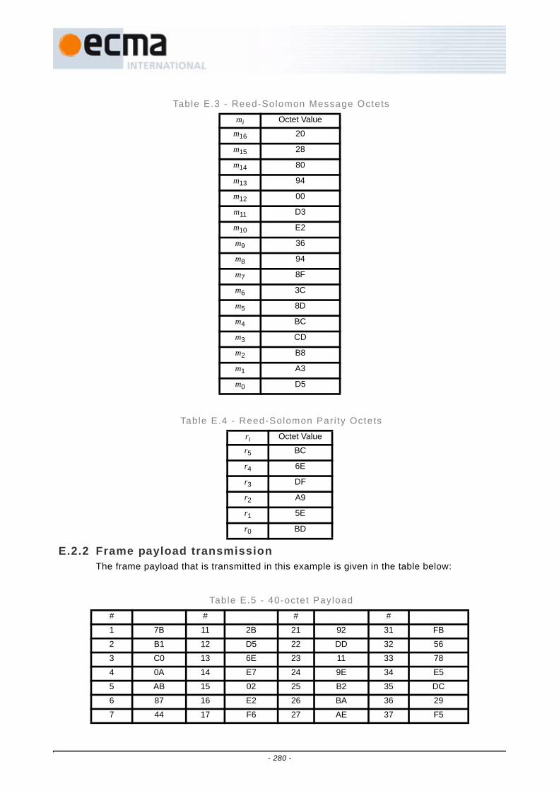
E.2.2 Frame payload transmissionThe frame payload that is transmitted in this example is given in the table below:
Table E.3 - Reed-Solomon Message Octetsmi Octet Value
m16 20
m15 28
m14 80
m13 94
m12 00
m11 D3
m10 E2
m9 36
m8 94
m7 8F
m6 3C
m5 8D
m4 BC
m3 CD
m2 B8
m1 A3
m0 D5
Table E.4 - Reed-Solomon Par i ty Octetsri Octet Value
r5 BC
r4 6E
r3 DF
r2 A9
r1 5E
r0 BD
Table E.5 - 40-octet Payload # # # #
1 7B 11 2B 21 92 31 FB
2 B1 12 D5 22 DD 32 56
3 C0 13 6E 23 11 33 78
4 0A 14 E7 24 9E 34 E5
5 AB 15 02 25 B2 35 DC
6 87 16 E2 26 BA 36 29
7 44 17 F6 27 AE 37 F5
- 280 -

The FCS for the 40-octet message as presented to the PHY SAP is given below in octetformat
DE 89 E6 B2 (55)
The FCS along with tail bits and potentially pad bits are then appended to the frame payloadto create the PSDU.
E.2.3 Complete transmitted packetThe symbol structure for the entire transmitted packet transmission is shown in Table E.6,where selected symbols of the packet are shown in Table E.7 through Table E.26. Each tabledescribes exactly one symbol (165 complex values). Note that the length of this packet isexactly 48 symbols.
8 71 18 EA 28 59 38 CC
9 33 19 0E 29 A4 39 00
10 C1 20 A5 30 08 40 3C
Table E.6 - Symbol structure for ent i re packet
Symbol Number Description
1 1st Packet/Frame Synchronization Sequence (samples 1 – 165)
2:24 Modulated version of Symbol 1: modulation depends on Cover Sequence(symbols not shown)
25 Channel Estimation Sequence (samples 3 961 – 4 125)
26:30 Same as Symbol 25 (symbols not shown)
31:42 PLCP header (samples 4 951 – 6 930)
43:end Payload (samples 6 931 – 7 913)
Table E.5 - 40-octet Payload (concluded)
- 281 -
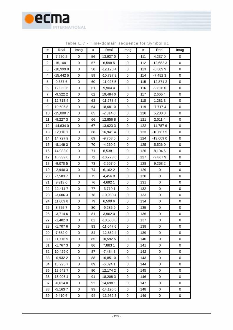
Table E.7 - Time-domain sequence for Symbol #1 # Real Imag # Real Imag # Real Imag
1 7,250 2 0 56 13,937 0 0 111 4,237 0 0
2 -15,100 1 0 57 6,598 5 0 112 -12,682 3 0
3 -10,999 0 0 58 -12,123 4 0 113 -0,389 9 0
4 -15,442 5 0 59 -10,797 9 0 114 -7,452 3 0
5 9,367 6 0 60 -11,025 5 0 115 -12,871 2 0
6 12,030 6 0 61 9,904 4 0 116 -9,826 0 0
7 -9,522 2 0 62 19,484 0 0 117 2,666 4 0
8 12,715 4 0 63 -11,278 4 0 118 1,281 3 0
9 10,605 8 0 64 18,681 0 0 119 -7,717 4 0
10 -15,000 7 0 65 -2,314 0 0 120 5,280 8 0
11 -9,227 3 0 66 12,856 8 0 121 2,011 4 0
12 -14,634 0 0 67 13,623 3 0 122 -11,787 6 0
13 12,110 1 0 68 16,941 4 0 123 -10,687 5 0
14 14,727 9 0 69 -9,768 5 0 124 -13,609 0 0
15 -8,149 3 0 70 -4,260 2 0 125 5,526 0 0
16 14,983 0 0 71 8,538 1 0 126 8,194 6 0
17 10,339 6 0 72 -10,773 6 0 127 -9,867 9 0
18 -9,070 5 0 73 -2,557 0 0 128 9,268 2 0
19 -2,940 3 0 74 6,162 2 0 129 0 0
20 -7,583 7 0 75 4,456 8 0 130 0 0
21 9,319 0 0 76 4,692 1 0 131 0 0
22 12,411 7 0 77 -3,710 1 0 132 0 0
23 -3,606 3 0 78 -10,950 4 0 133 0 0
24 11,609 8 0 79 6,599 6 0 134 0 0
25 8,755 7 0 80 -9,286 9 0 135 0 0
26 -3,714 6 0 81 3,962 0 0 136 0 0
27 -1,482 3 0 82 -10,608 0 0 137 0 0
28 -1,707 6 0 83 -11,047 6 0 138 0 0
29 7,682 0 0 84 -12,852 4 0 139 0 0
30 11,716 9 0 85 10,592 5 0 140 0 0
31 -1,767 3 0 86 7,883 1 0 141 0 0
32 10,429 0 0 87 -7,484 3 0 142 0 0
33 -0,932 2 0 88 10,851 0 0 143 0 0
34 13,225 7 0 89 -6,024 1 0 144 0 0
35 13,542 7 0 90 12,174 2 0 145 0 0
36 15,906 4 0 91 18,208 3 0 146 0 0
37 -6,614 0 0 92 14,698 1 0 147 0 0
38 -5,163 7 0 93 -14,195 5 0 148 0 0
39 9,410 6 0 94 -13,982 3 0 149 0 0
- 282 -

40 -9,854 7 0 95 10,421 3 0 150 0 0
41 -6,188 7 0 96 -18,566 1 0 151 0 0
42 13,128 5 0 97 4,674 4 0 152 0 0
43 12,291 3 0 98 -14,009 9 0 153 0 0
44 11,965 4 0 99 -20,048 4 0 154 0 0
45 -10,021 5 0 100 -16,379 2 0 155 0 0
46 -17,923 3 0 101 11,378 9 0 156 0 0
47 11,059 7 0 102 10,403 6 0 157 0 0
48 -17,746 6 0 103 -12,671 2 0 158 0 0
49 3,711 2 0 104 16,411 2 0 159 0 0
50 -14,509 2 0 105 -7,504 2 0 160 0 0
51 -15,957 2 0 106 10,573 7 0 161 0 0
52 -19,040 0 0 107 11,936 7 0 162 0 0
53 11,362 4 0 108 12,641 4 0 163 0 0
54 6,737 7 0 109 -13,599 0 0 164 0 0
55 -10,202 6 0 110 -7,337 4 0 165 0 0
Table E.7 - Time-domain sequence for Symbol #1 (concluded)
- 283 -

Table E.8 - Time-domain sequence for Symbol #25 # Real Imag # Real Imag # Real Imag
3 961 9,899 5 0 4 016 13,598 6 0 4 071 0,711 6 0
3 962 -7,256 2 0 4 017 3,781 8 0 4 072 12,003 7 0
3 963 -8,497 6 0 4 018 9,404 1 0 4 073 13,171 6 0
3 964 7,025 7 0 4 019 -8,819 7 0 4 074 0,300 3 0
3 965 0,392 8 0 4 020 -2,290 2 0 4 075 5,754 8 0
3 966 17,703 0 0 4 021 19,980 6 0 4 076 12,107 7 0
3 967 -11,790 1 0 4 022 -2,060 4 0 4 077 9,303 4 0
3 968 12,309 1 0 4 023 -6,113 9 0 4 078 -8,281 7 0
3 969 -11,756 3 0 4 024 -10,855 1 0 4 079 14,356 0 0
3 970 5,331 7 0 4 025 -9,899 5 0 4 080 -16,592 1 0
3 971 7,292 3 0 4 026 3,849 9 0 4 081 12,703 5 0
3 972 -2,596 8 0 4 027 5,920 5 0 4 082 -2,242 8 0
3 973 16,749 3 0 4 028 16,248 7 0 4 083 6,758 5 0
3 974 -3,823 5 0 4 029 4,913 2 0 4 084 8,742 2 0
3 975 -2,271 7 0 4 030 -15,280 5 0 4 085 -7,621 5 0
3 976 -0,080 8 0 4 031 11,670 6 0 4 086 -0,099 1 0
3 977 6,000 0 0 4 032 6,578 9 0 4 087 -9,980 5 0
3 978 -12,872 2 0 4 033 4,927 9 0 4 088 13,409 1 0
3 979 -12,999 7 0 4 034 6,795 8 0 4 089 0 0
3 980 -7,554 1 0 4 035 -2,812 9 0 4 090 0 0
3 981 17,424 9 0 4 036 -15,693 9 0 4 091 0 0
3 982 -12,291 5 0 4 037 -18,225 4 0 4 092 0 0
3 983 -3,980 2 0 4 038 -13,465 3 0 4 093 0 0
3 984 17,418 6 0 4 039 -15,821 4 0 4 094 0 0
3 985 0,559 7 0 4 040 -12,971 6 0 4 095 0 0
3 986 -11,305 5 0 4 041 -6,000 0 0 4 096 0 0
3 987 -20,268 7 0 4 042 13,953 8 0 4 097 0 0
3 988 -12,585 2 0 4 043 -4,030 9 0 4 098 0 0
3 989 -0,732 8 0 4 044 -16,536 9 0 4 099 0 0
3 990 18,688 1 0 4 045 9,057 2 0 4 100 0 0
3 991 1,350 8 0 4 046 -7,599 1 0 4 101 0 0
3 992 -10,986 4 0 4 047 7,567 7 0 4 102 0 0
3 993 18,384 8 0 4 048 0,710 3 0 4 103 0 0
3 994 -3,466 2 0 4 049 -0,074 4 0 4 104 0 0
3 995 -0,916 3 0 4 050 15,758 9 0 4 105 0 0
3 996 2,091 1 0 4 051 -16,763 6 0 4 106 0 0
3 997 -13,933 1 0 4 052 -5,454 3 0 4 107 0 0
3 998 -18,009 5 0 4 053 10,030 5 0 4 108 0 0
3 999 5,953 0 0 4 054 13,822 6 0 4 109 0 0
- 284 -

4 000 8,222 1 0 4 055 -1,722 4 0 4 110 0 0
4 001 -15,858 3 0 4 056 16,196 3 0 4 111 0 0
4 002 5,545 9 0 4 057 -1,414 2 0 4 112 0 0
4 003 -14,449 1 0 4 058 -9,248 4 0 4 113 0 0
4 004 -2,293 3 0 4 059 17,304 9 0 4 114 0 0
4 005 -9,606 6 0 4 060 -5,893 1 0 4 115 0 0
4 006 -14,018 8 0 4 061 -17,716 1 0 4 116 0 0
4 007 13,161 2 0 4 062 -11,728 5 0 4 117 0 0
4 008 -8,965 7 0 4 063 1,041 3 0 4 118 0 0
4 009 -18,828 4 0 4 064 14,632 4 0 4 119 0 0
4 010 -10,138 8 0 4 065 17,029 9 0 4 120 0 0
4 011 -4,476 8 0 4 066 4,962 2 0 4 121 0 0
4 012 0,070 5 0 4 067 -16,878 1 0 4 122 0 0
4 013 1,871 3 0 4 068 15,239 3 0 4 123 0 0
4 014 15,928 3 0 4 069 0,739 5 0 4 124 0 0
4 015 18,495 4 0 4 070 -14,111 5 0 4 125 0 0
Table E.8 - Time-domain sequence for Symbol #25 (concluded)
- 285 -

Table E.9 - Time-domain sequence for Symbol #31 # Real Imag # Real Imag # Real Imag
4 951 -24,041 6 0 5 006 4,945 8 0 5 061 5,146 5 0
4 952 17,093 4 0 5 007 -1,372 1 0 5 062 4,055 9 0
4 953 -10,188 5 0 5 008 -0,313 6 0 5 063 2,000 0 0
4 954 -3,791 7 0 5 009 0,829 3 0 5 064 -10,875 7 0
4 955 6,111 3 0 5 010 -21,867 7 0 5 065 26,801 5 0
4 956 3,168 5 0 5 011 23,862 6 0 5 066 11,900 7 0
4 957 -4,379 5 0 5 012 19,146 9 0 5 067 -5,922 4 0
4 958 -18,124 9 0 5 013 -9,953 2 0 5 068 4,835 9 0
4 959 0,865 9 0 5 014 11,044 2 0 5 069 22,865 1 0
4 960 17,061 0 0 5 015 -4,242 6 0 5 070 -5,862 9 0
4 961 5,475 3 0 5 016 -28,150 2 0 5 071 -3,799 5 0
4 962 6,869 4 0 5 017 -10,986 2 0 5 072 -0,738 1 0
4 963 8,705 9 0 5 018 -0,525 7 0 5 073 8,617 4 0
4 964 5,613 9 0 5 019 -9,962 5 0 5 074 -4,699 7 0
4 965 16,472 4 0 5 020 -1,596 8 0 5 075 -11,580 8 0
4 966 -11,353 8 0 5 021 4,790 4 0 5 076 -20,124 2 0
4 967 5,171 6 0 5 022 6,034 4 0 5 077 -13,119 4 0
4 968 0,828 1 0 5 023 -0,664 9 0 5 078 10,039 4 0
4 969 -13,324 3 0 5 024 -16,643 2 0 5 079 0 0
4 970 12,766 5 0 5 025 6,445 8 0 5 080 0 0
4 971 -8,500 5 0 5 026 7,996 1 0 5 081 0 0
4 972 0,235 5 0 5 027 8,193 3 0 5 082 0 0
4 973 14,946 6 0 5 028 -2,774 2 0 5 083 0 0
4 974 1,926 2 0 5 029 -9,291 1 0 5 084 0 0
4 975 -2,742 2 0 5 030 -4,107 4 0 5 085 0 0
4 976 12,660 4 0 5 031 -10,828 4 0 5 086 0 0
4 977 21,444 5 0 5 032 17,594 5 0 5 087 0 0
4 978 14,554 8 0 5 033 -0,206 3 0 5 088 0 0
4 979 23,842 5 0 5 034 3,034 4 0 5 089 0 0
4 980 -7,132 0 0 5 035 4,936 9 0 5 090 0 0
4 981 3,192 8 0 5 036 -23,943 5 0 5 091 0 0
4 982 -11,724 0 0 5 037 1,595 8 0 5 092 0 0
4 983 9,899 5 0 5 038 -4,266 5 0 5 093 0 0
4 984 12,001 2 0 5 039 13,570 6 0 5 094 0 0
4 985 -5,672 2 0 5 040 8,634 2 0 5 095 0 0
4 986 0,851 2 0 5 041 7,341 1 0 5 096 0 0
4 987 -4,405 7 0 5 042 10,494 7 0 5 097 0 0
4 988 -4,256 3 0 5 043 0,160 0 0 5 098 0 0
4 989 12,590 5 0 5 044 -5,029 7 0 5 099 0 0
- 286 -

4 990 15,079 9 0 5 045 -21,820 9 0 5 100 0 0
4 991 -21,747 3 0 5 046 -7,106 5 0 5 101 0 0
4 992 -6,828 7 0 5 047 -9,899 5 0 5 102 0 0
4 993 -10,080 5 0 5 048 9,373 6 0 5 103 0 0
4 994 7,184 9 0 5 049 -2,607 9 0 5 104 0 0
4 995 0,404 1 0 5 050 -5,587 6 0 5 105 0 0
4 996 -6,577 3 0 5 051 -0,713 6 0 5 106 0 0
4 997 8,686 5 0 5 052 8,616 8 0 5 107 0 0
4 998 4,465 9 0 5 053 -4,333 3 0 5 108 0 0
4 999 -2,000 0 0 5 054 -4,418 3 0 5 109 0 0
5 000 -13,178 6 0 5 055 -18,051 7 0 5 110 0 0
5 001 -4,502 4 0 5 056 -9,145 7 0 5 111 0 0
5 002 8,665 9 0 5 057 3,240 9 0 5 112 0 0
5 003 -15,484 6 0 5 058 6,781 2 0 5 113 0 0
5 004 -14,373 8 0 5 059 2,981 0 0 5 114 0 0
5 005 -4,761 9 0 5 060 -10,437 2 0 5 115 0 0
Table E.9 - Time-domain sequence for Symbol #31 (concluded)
- 287 -

Table E.10 - Time-domain sequence for Symbol #32 # Real Imag # Real Imag # Real Imag
5 116 24,041 6 0 5 171 -4,945 8 0 5 226 -5,146 5 0
5 117 -17,093 4 0 5 172 1,372 1 0 5 227 -4,055 9 0
5 118 10,188 5 0 5 173 0,313 6 0 5 228 -2,000 0 0
5 119 3,791 7 0 5 174 -0,829 3 0 5 229 10,875 7 0
5 120 -6,111 3 0 5 175 21,867 7 0 5 230 -26,801 5 0
5 121 -3,168 5 0 5 176 -23,862 6 0 5 231 -11,900 7 0
5 122 4,379 5 0 5 177 -19,146 9 0 5 232 5,922 4 0
5 123 18,124 9 0 5 178 9,953 2 0 5 233 -4,835 9 0
5 124 -0,865 9 0 5 179 -11,044 2 0 5 234 -22,865 1 0
5 125 -17,061 0 0 5 180 4,242 6 0 5 235 5,862 9 0
5 126 -5,475 3 0 5 181 28,150 2 0 5 236 3,799 5 0
5 127 -6,869 4 0 5 182 10,986 2 0 5 237 0,738 1 0
5 128 -8,705 9 0 5 183 0,525 7 0 5 238 -8,617 4 0
5 129 -5,613 9 0 5 184 9,962 5 0 5 239 4,699 7 0
5 130 -16,472 4 0 5 185 1,596 8 0 5 240 11,580 8 0
5 131 11,353 8 0 5 186 -4,790 4 0 5 241 20,124 2 0
5 132 -5,171 6 0 5 187 -6,034 4 0 5 242 13,119 4 0
5 133 -0,828 1 0 5 188 0,664 9 0 5 243 -10,039 4 0
5 134 13,324 3 0 5 189 16,643 2 0 5 244 0 0
5 135 -12,766 5 0 5 190 -6,445 8 0 5 245 0 0
5 136 8,500 5 0 5 191 -7,996 1 0 5 246 0 0
5 137 -0,235 5 0 5 192 -8,193 3 0 5 247 0 0
5 138 -14,946 6 0 5 193 2,774 2 0 5 248 0 0
5 139 -1,926 2 0 5 194 9,291 1 0 5 249 0 0
5 140 2,742 2 0 5 195 4,107 4 0 5 250 0 0
5 141 -12,660 4 0 5 196 10,828 4 0 5 251 0 0
5 142 -21,444 5 0 5 197 -17,594 5 0 5 252 0 0
5 143 -14,554 8 0 5 198 0,206 3 0 5 253 0 0
5 144 -23,842 5 0 5 199 -3,034 4 0 5 254 0 0
5 145 7,132 0 0 5 200 -4,936 9 0 5 255 0 0
5 146 -3,192 8 0 5 201 23,943 5 0 5 256 0 0
5 147 11,724 0 0 5 202 -1,595 8 0 5 257 0 0
5 148 -9,899 5 0 5 203 4,266 5 0 5 258 0 0
5 149 -12,001 2 0 5 204 -13,570 6 0 5 259 0 0
5 150 5,672 2 0 5 205 -8,634 2 0 5 260 0 0
5 151 -0,851 2 0 5 206 -7,341 1 0 5 261 0 0
5 152 4,405 7 0 5 207 -10,494 7 0 5 262 0 0
5 153 4,256 3 0 5 208 -0,160 0 0 5 263 0 0
5 154 -12,590 5 0 5 209 5,029 7 0 5 264 0 0
- 288 -

5 155 -15,079 9 0 5 210 21,820 9 0 5 265 0 0
5 156 21,747 3 0 5 211 7,106 5 0 5 266 0 0
5 157 6,828 7 0 5 212 9,899 5 0 5 267 0 0
5 158 10,080 5 0 5 213 -9,373 6 0 5 268 0 0
5 159 -7,184 9 0 5 214 2,607 9 0 5 269 0 0
5 160 -0,404 1 0 5 215 5,587 6 0 5 270 0 0
5 161 6,577 3 0 5 216 0,713 6 0 5 271 0 0
5 162 -8,686 5 0 5 217 -8,616 8 0 5 272 0 0
5 163 -4,465 9 0 5 218 4,333 3 0 5 273 0 0
5 164 2,000 0 0 5 219 4,418 3 0 5 274 0 0
5 165 13,178 6 0 5 220 18,051 7 0 5 275 0 0
5 166 4,502 4 0 5 221 9,145 7 0 5 276 0 0
5 167 -8,665 9 0 5 222 -3,240 9 0 5 277 0 0
5 168 15,484 6 0 5 223 -6,781 2 0 5 278 0 0
5 169 14,373 8 0 5 224 -2,981 0 0 5 279 0 0
5 170 4,761 9 0 5 225 10,437 2 0 5 280 0 0
Table E.10 - Time-domain sequence for Symbol #32 (concluded)
- 289 -

Table E.11 - Time-domain sequence for Symbol #33 # Real Imag # Real Imag # Real Imag
5 281 4,242 6 0 5 336 18,538 8 0 5 391 5,960 4 0
5 282 -13,153 7 0 5 337 1,982 0 0 5 392 -7,186 9 0
5 283 -17,180 2 0 5 338 3,489 2 0 5 393 4,000 0 0
5 284 -10,909 2 0 5 339 22,160 0 0 5 394 -6,247 9 0
5 285 -0,136 6 0 5 340 9,917 9 0 5 395 -6,493 6 0
5 286 -2,759 0 0 5 341 18,886 5 0 5 396 5,762 5 0
5 287 -0,554 0 0 5 342 32,017 0 0 5 397 2,823 9 0
5 288 11,196 9 0 5 343 -5,268 3 0 5 398 -12,927 6 0
5 289 -5,262 0 0 5 344 -3,507 8 0 5 399 -2,592 2 0
5 290 -15,181 7 0 5 345 -9,899 5 0 5 400 -1,383 5 0
5 291 -3,261 5 0 5 346 -3,544 4 0 5 401 -16,124 2 0
5 292 14,676 5 0 5 347 14,876 3 0 5 402 -16,635 3 0
5 293 12,501 6 0 5 348 0,405 4 0 5 403 3,083 5 0
5 294 1,357 5 0 5 349 6,660 6 0 5 404 20,504 1 0
5 295 -4,818 0 0 5 350 -9,721 3 0 5 405 3,925 1 0
5 296 -4,870 1 0 5 351 4,619 9 0 5 406 3,525 9 0
5 297 -0,142 1 0 5 352 27,441 9 0 5 407 22,777 9 0
5 298 -7,981 5 0 5 353 -1,566 5 0 5 408 2,100 0 0
5 299 0,534 1 0 5 354 -7,072 2 0 5 409 0 0
5 300 -3,771 7 0 5 355 -12,816 2 0 5 410 0 0
5 301 17,360 7 0 5 356 -19,555 0 0 5 411 0 0
5 302 12,664 4 0 5 357 -9,648 1 0 5 412 0 0
5 303 -15,240 6 0 5 358 -6,791 7 0 5 413 0 0
5 304 -2,965 5 0 5 359 -2,163 2 0 5 414 0 0
5 305 -18,474 6 0 5 360 3,540 9 0 5 415 0 0
5 306 6,036 0 0 5 361 -28,142 1 0 5 416 0 0
5 307 7,115 0 0 5 362 18,397 5 0 5 417 0 0
5 308 0,931 9 0 5 363 0,684 0 0 5 418 0 0
5 309 -0,973 4 0 5 364 -16,201 5 0 5 419 0 0
5 310 -2,415 4 0 5 365 -13,001 5 0 5 420 0 0
5 311 -1,135 5 0 5 366 11,111 9 0 5 421 0 0
5 312 0,405 7 0 5 367 11,847 8 0 5 422 0 0
5 313 -4,242 6 0 5 368 -8,790 4 0 5 423 0 0
5 314 -3,306 4 0 5 369 4,332 5 0 5 424 0 0
5 315 13,880 5 0 5 370 -4,857 4 0 5 425 0 0
5 316 -4,796 1 0 5 371 23,767 5 0 5 426 0 0
5 317 -8,511 5 0 5 372 -11,332 7 0 5 427 0 0
5 318 7,299 5 0 5 373 -0,181 5 0 5 428 0 0
5 319 13,512 4 0 5 374 -13,402 5 0 5 429 0 0
- 290 -

5320 -1,774 1 0 5 375 -10,717 2 0 5 430 0 0
5 321 -0,179 6 0 5 376 6,491 4 0 5 431 0 0
5 322 6,215 4 0 5 377 4,242 6 0 5 432 0 0
5 323 -16,889 9 0 5 378 -2,145 1 0 5 433 0 0
5 324 11,916 2 0 5 379 -2,332 9 0 5 434 0 0
5 325 1,722 1 0 5 380 -21,418 1 0 5 435 0 0
5 326 -14,080 9 0 5 381 7,644 4 0 5 436 0 0
5 327 6,677 7 0 5 382 -4,090 2 0 5 437 0 0
5 328 5,848 8 0 5 383 -11,921 4 0 5 438 0 0
5 329 -4,000 0 0 5 384 9,541 3 0 5 439 0 0
5 330 -9,332 1 0 5 385 1,351 2 0 5 440 0 0
5 331 7,345 6 0 5 386 0,692 3 0 5 441 0 0
5 332 -12,885 9 0 5 387 -11,844 8 0 5 442 0 0
5 333 -1,526 2 0 5 388 27,383 1 0 5 443 0 0
5 334 3,108 7 0 5 389 -14,918 8 0 5 444 0 0
5 335 11,641 9 0 5 390 4,476 4 0 5 445 0 0
Table E.11 - Time-domain sequence for Symbol #33 (concluded)
- 291 -
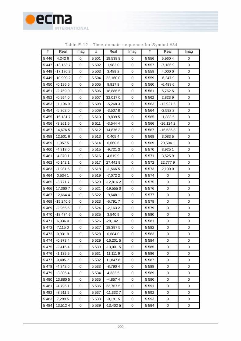
Table E.12 - Time-domain sequence for Symbol #34 # Real Imag # Real Imag # Real Imag
5 446 4,242 6 0 5 501 18,538 8 0 5 556 5,960 4 0
5 447 -13,153 7 0 5 502 1,982 0 0 5 557 -7,186 9 0
5 448 -17,180 2 0 5 503 3,489 2 0 5 558 4,000 0 0
5 449 -10,909 2 0 5 504 22,160 0 0 5 559 -6,247 9 0
5 450 -0,136 6 0 5 505 9,917 9 0 5 560 -6,493 6 0
5 451 -2,759 0 0 5 506 18,886 5 0 5 561 5,762 5 0
5 452 -0,554 0 0 5 507 32,017 0 0 5 562 2,823 9 0
5 453 11,196 9 0 5 508 -5,268 3 0 5 563 -12,927 6 0
5 454 -5,262 0 0 5 509 -3,507 8 0 5 564 -2,592 2 0
5 455 -15,181 7 0 5 510 -9,899 5 0 5 565 -1,383 5 0
5 456 -3,261 5 0 5 511 -3,544 4 0 5 566 -16,124 2 0
5 457 14,676 5 0 5 512 14,876 3 0 5 567 -16,635 3 0
5 458 12,501 6 0 5 513 0,405 4 0 5 568 3,083 5 0
5 459 1,357 5 0 5 514 6,660 6 0 5 569 20,504 1 0
5 460 -4,818 0 0 5 515 -9,721 3 0 5 570 3,925 1 0
5 461 -4,870 1 0 5 516 4,619 9 0 5 571 3,525 9 0
5 462 -0,142 1 0 5 517 27,441 9 0 5 572 22,777 9 0
5 463 -7,981 5 0 5 518 -1,566 5 0 5 573 2,100 0 0
5 464 0,534 1 0 5 519 -7,072 2 0 5 574 0 0
5 465 -3,771 7 0 5 520 -12,816 2 0 5 575 0 0
5 466 17,360 7 0 5 521 -19,555 0 0 5 576 0 0
5 467 12,664 4 0 5 522 -9,648 1 0 5 577 0 0
5 468 -15,240 6 0 5 523 -6,791 7 0 5 578 0 0
5 469 -2,965 5 0 5 524 -2,163 2 0 5 579 0 0
5 470 -18,474 6 0 5 525 3,540 9 0 5 580 0 0
5 471 6,036 0 0 5 526 -28,142 1 0 5 581 0 0
5 472 7,115 0 0 5 527 18,397 5 0 5 582 0 0
5 473 0,931 9 0 5 528 0,684 0 0 5 583 0 0
5 474 -0,973 4 0 5 529 -16,201 5 0 5 584 0 0
5 475 -2,415 4 0 5 530 -13,001 5 0 5 585 0 0
5 476 -1,135 5 0 5 531 11,111 9 0 5 586 0 0
5 477 0,405 7 0 5 532 11,847 8 0 5 587 0 0
5 478 -4,242 6 0 5 533 -8,790 4 0 5 588 0 0
5 479 -3,306 4 0 5 534 4,332 5 0 5 589 0 0
5 480 13,880 5 0 5 535 -4,857 4 0 5 590 0 0
5 481 -4,796 1 0 5 536 23,767 5 0 5 591 0 0
5 482 -8,511 5 0 5 537 -11,332 7 0 5 592 0 0
5 483 7,299 5 0 5 538 -0,181 5 0 5 593 0 0
5 484 13,512 4 0 5 539 -13,402 5 0 5 594 0 0
- 292 -

5 485 -1,774 1 0 5 540 -10,717 2 0 5 595 0 0
5 486 -0,179 6 0 5 541 6,491 4 0 5 596 0 0
5 487 6,215 4 0 5 542 4,242 6 0 5 597 0 0
5 488 -16,889 9 0 5 543 -2,145 1 0 5 598 0 0
5 489 11,916 2 0 5 544 -2,332 9 0 5 599 0 0
5 490 1,722 1 0 5 545 -21,418 1 0 5 600 0 0
5 491 -14,080 9 0 5 546 7,644 4 0 5 601 0 0
5 492 6,677 7 0 5 547 -4,090 2 0 5 602 0 0
5 493 5,848 8 0 5 548 -11,921 4 0 5 603 0 0
5 494 -4,000 0 0 5 549 9,541 3 0 5 604 0 0
5 495 -9,332 1 0 5 550 1,351 2 0 5 605 0 0
5 496 7,345 6 0 5 551 0,692 3 0 5 606 0 0
5 497 -12,885 9 0 5 552 -11,844 8 0 5 607 0 0
5 498 -1,526 2 0 5 553 27,383 1 0 5 608 0 0
5 499 3,108 7 0 5 554 -14,918 8 0 5 609 0 0
5 500 11,641 9 0 5 555 4,476 4 0 5 610 0 0
Table E.12 - Time-domain sequence for Symbol #34 (concluded)
- 293 -

Table E.13 - Time-domain sequence for Symbol #35 # Real Imag # Real Imag # Real Imag
5 611 -24,041 6 0 5 666 -2,905 0 0 5 721 -17,716 7 0
5 612 1,228 5 0 5 667 22,453 7 0 5 722 12,159 0 0
5 613 6,228 1 0 5 668 -1,779 1 0 5 723 6,828 4 0
5 614 -2,440 5 0 5 669 1,393 2 0 5 724 -8,110 8 0
5 615 -16,692 2 0 5 670 5,204 1 0 5 725 7,932 9 0
5 616 12,587 6 0 5 671 4,591 9 0 5 726 7,108 7 0
5 617 -2,784 8 0 5 672 7,875 0 0 5 727 9,181 0 0
5 618 20,561 9 0 5 673 14,463 7 0 5 728 2,526 2 0
5 619 -6,776 7 0 5 674 3,692 8 0 5 729 0,147 7 0
5 620 -5,367 2 0 5 675 -15,556 3 0 5 730 -0,462 9 0
5 621 1,393 1 0 5 676 -18,453 5 0 5 731 -4,311 6 0
5 622 -8,722 2 0 5 677 -17,890 8 0 5 732 -3,914 4 0
5 623 5,541 2 0 5 678 -4,724 7 0 5 733 5,042 7 0
5 624 8,274 2 0 5 679 2,676 1 0 5 734 -14,041 5 0
5 625 -11,132 6 0 5 680 5,205 0 0 5 735 5,323 1 0
5 626 13,655 3 0 5 681 -16,375 1 0 5 736 -10,845 6 0
5 627 14,970 6 0 5 682 -20,123 9 0 5 737 21,948 3 0
5 628 -7,353 9 0 5 683 -3,081 2 0 5 738 14,281 3 0
5 629 4,312 9 0 5 684 -22,418 2 0 5 739 0 0
5 630 3,561 5 0 5 685 -12,550 4 0 5 740 0 0
5 631 12,579 0 0 5 686 -12,916 3 0 5 741 0 0
5 632 -5,137 7 0 5 687 -3,305 0 0 5 742 0 0
5 633 -0,951 6 0 5 688 -4,287 9 0 5 743 0 0
5 634 -11,666 6 0 5 689 -16,996 8 0 5 744 0 0
5 635 4,120 0 0 5 690 0,918 9 0 5 745 0 0
5 636 -6,594 1 0 5 691 18,970 6 0 5 746 0 0
5 637 -1,081 1 0 5 692 19,664 7 0 5 747 0 0
5 638 -4,568 0 0 5 693 9,996 3 0 5 748 0 0
5 639 -4,964 3 0 5 694 -8,369 3 0 5 749 0 0
5 640 12,156 9 0 5 695 -13,368 8 0 5 750 0 0
5 641 19,514 6 0 5 696 -4,593 3 0 5 751 0 0
5 642 -0,942 9 0 5 697 15,297 3 0 5 752 0 0
5 643 1,414 2 0 5 698 -9,813 0 0 5 753 0 0
5 644 -7,056 7 0 5 699 6,022 1 0 5 754 0 0
5 645 -8,059 3 0 5 700 16,230 0 0 5 755 0 0
5 646 5,036 2 0 5 701 -9,218 3 0 5 756 0 0
5 647 -4,148 2 0 5 702 2,185 8 0 5 757 0 0
5 648 16,504 3 0 5 703 -7,293 8 0 5 758 0 0
5 649 -20,034 7 0 5 704 6,677 7 0 5 759 0 0
- 294 -

5 650 -9,187 6 0 5 705 -11,689 8 0 5 760 0 0
5 651 18,305 7 0 5 706 -3,190 0 0 5 761 0 0
5 652 22,876 2 0 5 707 9,899 5 0 5 762 0 0
5 653 -8,894 1 0 5 708 12,531 5 0 5 763 0 0
5 654 -2,753 2 0 5 709 -11,169 5 0 5 764 0 0
5 655 18,475 3 0 5 710 -0,661 5 0 5 765 0 0
5 656 2,080 6 0 5 711 -6,806 3 0 5 766 0 0
5 657 22,295 5 0 5 712 -9,543 8 0 5 767 0 0
5 658 5,922 1 0 5 713 -5,160 7 0 5 768 0 0
5 659 -1,171 6 0 5 714 -3,526 7 0 5 769 0 0
5 660 2,863 9 0 5 715 19,836 4 0 5 770 0 0
5 661 -2,664 4 0 5 716 -3,719 4 0 5 771 0 0
5 662 -9,505 8 0 5 717 12,601 1 0 5 772 0 0
5 663 -17,361 8 0 5 718 -9,020 6 0 5 773 0 0
5 664 9,765 3 0 5 719 -7,054 7 0 5 774 0 0
5 665 -13,451 9 0 5 720 5,382 8 0 5 775 0 0
Table E.13 - Time-domain sequence for Symbol #35 (concluded)
- 295 -

Table E.14 - Time-domain sequence for Symbol #36 # Real Imag # Real Imag # Real Imag
5 776 24,041 6 0 5 831 2,905 0 0 5 886 17,716 7 0
5 777 -1,228 5 0 5 832 -22,453 7 0 5 887 -12,159 0 0
5 778 -6,228 1 0 5 833 1,779 1 0 5 888 -6,828 4 0
5 779 2,440 5 0 5 834 -1,393 2 0 5 889 8,110 8 0
5 780 16,692 2 0 5 835 -5,204 1 0 5 890 -7,932 9 0
5 781 -12,587 6 0 5 836 -4,591 9 0 5 891 -7,108 7 0
5 782 2,784 8 0 5 837 -7,875 0 0 5 892 -9,181 0 0
5 783 -20,561 9 0 5 838 -14,463 7 0 5 893 -2,526 2 0
5 784 6,776 7 0 5 839 -3,692 8 0 5 894 -0,147 7 0
5 785 5,367 2 0 5 840 15,556 3 0 5 895 0,462 9 0
5 786 -1,393 1 0 5 841 18,453 5 0 5 896 4,311 6 0
5 787 8,722 2 0 5 842 17,890 8 0 5 897 3,914 4 0
5 788 -5,541 2 0 5 843 4,724 7 0 5 898 -5,042 7 0
5 789 -8,274 2 0 5 844 -2,676 1 0 5 899 14,041 5 0
5 790 11,132 6 0 5 845 -5,205 0 0 5 900 -5,323 1 0
5 791 -13,655 3 0 5 846 16,375 1 0 5 901 10,845 6 0
5 792 -14,970 6 0 5 847 20,123 9 0 5 902 -21,948 3 0
5 793 7,353 9 0 5 848 3,081 2 0 5 903 -14,281 3 0
5 794 -4,312 9 0 5 849 22,418 2 0 5 904 0 0
5 795 -3,561 5 0 5 850 12,550 4 0 5 905 0 0
5 796 -12,579 0 0 5 851 12,916 3 0 5 906 0 0
5 797 5,137 7 0 5 852 3,305 0 0 5 907 0 0
5 798 0,951 6 0 5 853 4,287 9 0 5 908 0 0
5 799 11,666 6 0 5 854 16,996 8 0 5 909 0 0
5 800 -4,120 0 0 5 855 -0,918 9 0 5 910 0 0
5 801 6,594 1 0 5 856 -18,970 6 0 5 911 0 0
5 802 1,081 1 0 5 857 -19,664 7 0 5 912 0 0
5 803 4,568 0 0 5 858 -9,996 3 0 5 913 0 0
5 804 4,964 3 0 5 859 8,369 3 0 5 914 0 0
5 805 -12,156 9 0 5 860 13,368 8 0 5 915 0 0
5 806 -19,514 6 0 5 861 4,593 3 0 5 916 0 0
5 807 0,942 9 0 5 862 -15,297 3 0 5 917 0 0
5 808 -1,414 2 0 5 863 9,813 0 0 5 918 0 0
5 809 7,056 7 0 5 864 -6,022 1 0 5 919 0 0
5 810 8,059 3 0 5 865 -16,230 0 0 5 920 0 0
5 811 -5,036 2 0 5 866 9,218 3 0 5 921 0 0
5 812 4,148 2 0 5 867 -2,185 8 0 5 922 0 0
5 813 -16,504 3 0 5 868 7,293 8 0 5 923 0 0
5 814 20,034 7 0 5 869 -6,677 7 0 5 924 0 0
- 296 -
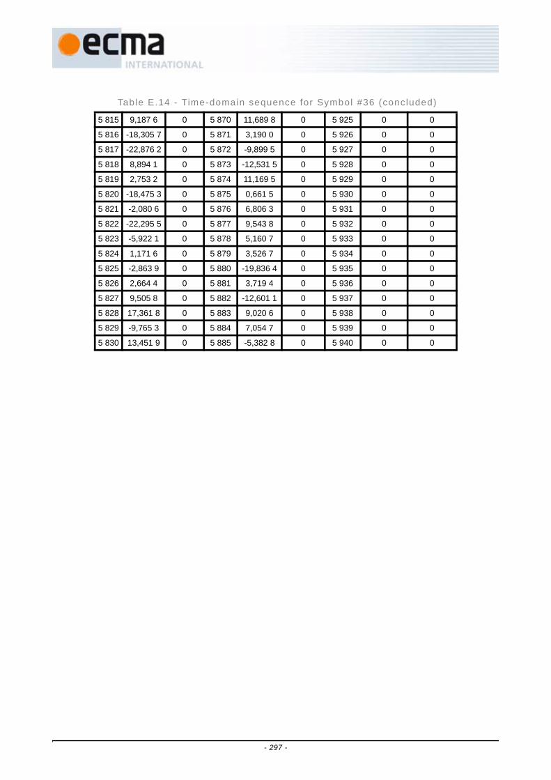
5 815 9,187 6 0 5 870 11,689 8 0 5 925 0 0
5 816 -18,305 7 0 5 871 3,190 0 0 5 926 0 0
5 817 -22,876 2 0 5 872 -9,899 5 0 5 927 0 0
5 818 8,894 1 0 5 873 -12,531 5 0 5 928 0 0
5 819 2,753 2 0 5 874 11,169 5 0 5 929 0 0
5 820 -18,475 3 0 5 875 0,661 5 0 5 930 0 0
5 821 -2,080 6 0 5 876 6,806 3 0 5 931 0 0
5 822 -22,295 5 0 5 877 9,543 8 0 5 932 0 0
5 823 -5,922 1 0 5 878 5,160 7 0 5 933 0 0
5 824 1,171 6 0 5 879 3,526 7 0 5 934 0 0
5 825 -2,863 9 0 5 880 -19,836 4 0 5 935 0 0
5 826 2,664 4 0 5 881 3,719 4 0 5 936 0 0
5 827 9,505 8 0 5 882 -12,601 1 0 5 937 0 0
5 828 17,361 8 0 5 883 9,020 6 0 5 938 0 0
5 829 -9,765 3 0 5 884 7,054 7 0 5 939 0 0
5 830 13,451 9 0 5 885 -5,382 8 0 5 940 0 0
Table E.14 - Time-domain sequence for Symbol #36 (concluded)
- 297 -

Table E.15 - Time-domain sequence for Symbol #37 # Real Imag # Real Imag # Real Imag
5 941 4,242 6 0 5 996 -4,308 9 0 6 051 -13,579 6 0
5 942 -1,846 8 0 5 997 10,856 5 0 6 052 19,335 3 0
5 943 -15,106 1 0 5 998 -11,090 5 0 6 053 -8,828 4 0
5 944 2,741 3 0 5 999 -14,078 8 0 6 054 -10,115 3 0
5 945 12,470 4 0 6 000 20,292 9 0 6 055 -16,265 9 0
5 946 10,358 6 0 6 001 11,948 1 0 6 056 0,832 9 0
5 947 20,588 8 0 6 002 4,304 8 0 6 057 5,777 4 0
5 948 10,983 0 0 6 003 -5,709 3 0 6 058 0,651 0 0
5 949 -3,211 5 0 6 004 -7,306 6 0 6 059 23,253 0 0
5 950 6,570 8 0 6 005 18,384 8 0 6 060 9,742 3 0
5 951 17,327 5 0 6 006 1,979 0 0 6 061 -19,341 7 0
5 952 23,297 3 0 6 007 4,562 3 0 6 062 5,850 9 0
5 953 -3,036 9 0 6 008 9,525 9 0 6 063 -0,610 5 0
5 954 -8,283 6 0 6 009 6,519 6 0 6 064 8,761 1 0
5 955 13,502 1 0 6 010 -19,152 1 0 6 065 -0,586 6 0
5 956 -4,238 1 0 6 011 -7,644 0 0 6 066 -18,059 7 0
5 957 -15,313 7 0 6 012 -0,076 9 0 6 067 -0,386 0 0
5 958 -10,092 6 0 6 013 10,039 9 0 6 068 -9,098 8 0
5 959 8,850 8 0 6 014 -1,611 9 0 6 069 0 0
5 960 -1,596 5 0 6 015 -5,491 4 0 6 070 0 0
5 961 -7,539 1 0 6 016 -6,553 8 0 6 071 0 0
5 962 -1,377 2 0 6 017 -21,001 0 0 6 072 0 0
5 963 -5,089 5 0 6 018 9,380 4 0 6 073 0 0
5 964 -6,773 7 0 6 019 2,276 2 0 6 074 0 0
5 965 6,341 2 0 6 020 -16,033 9 0 6 075 0 0
5 966 -10,355 0 0 6 021 -7,313 7 0 6 076 0 0
5 967 -1,263 4 0 6 022 13,085 8 0 6 077 0 0
5 968 18,016 8 0 6 023 -13,897 8 0 6 078 0 0
5 969 3,493 0 0 6 024 -14,068 8 0 6 079 0 0
5 970 8,535 6 0 6 025 -20,540 7 0 6 080 0 0
5 971 6,127 8 0 6 026 -16,748 4 0 6 081 0 0
5 972 -4,488 6 0 6 027 9,833 4 0 6 082 0 0
5 973 -7,071 1 0 6 028 6,034 5 0 6 083 0 0
5 974 -11,101 3 0 6 029 -14,826 5 0 6 084 0 0
5 975 -1,002 0 0 6 030 -3,270 9 0 6 085 0 0
5 976 11,818 8 0 6 031 -5,061 7 0 6 086 0 0
5 977 -11,358 6 0 6 032 -3,457 2 0 6 087 0 0
5 978 3,548 4 0 6 033 -12,511 3 0 6 088 0 0
5 979 8,084 4 0 6 034 -0,366 0 0 6 089 0 0
- 298 -

5 980 3,398 1 0 6 035 5,267 8 0 6 090 0 0
5 981 -5,495 0 0 6 036 7,831 7 0 6 091 0 0
5 982 -1,081 8 0 6 037 1,414 2 0 6 092 0 0
5 983 7,661 2 0 6 038 8,031 4 0 6 093 0 0
5 984 -9,313 4 0 6 039 2,877 7 0 6 094 0 0
5 985 5,287 9 0 6 040 -2,500 7 0 6 095 0 0
5 986 10,778 2 0 6 041 10,711 7 0 6 096 0 0
5 987 -5,557 6 0 6 042 -22,368 5 0 6 097 0 0
5 988 -2,933 1 0 6 043 1,488 8 0 6 098 0 0
5 989 3,171 6 0 6 044 -11,438 7 0 6 099 0 0
5 990 -5,008 0 0 6 045 4,323 4 0 6 100 0 0
5 991 -13,332 6 0 6 046 -24,571 2 0 6 101 0 0
5 992 -9,003 4 0 6 047 22,203 3 0 6 102 0 0
5 993 -7,354 5 0 6 048 5,834 1 0 6 103 0 0
5 994 20,210 3 0 6 049 5,093 2 0 6 104 0 0
5 995 15,426 2 0 6 050 27,960 7 0 6 105 0 0
Table E.15 - Time-domain sequence for Symbol #37 (concluded)
- 299 -

Table E.16 - Time-domain sequence for Symbol #38 # Real Imag # Real Imag # Real Imag
6 106 -4,242 6 0 6 161 4,308 9 0 6 216 13,579 6 0
6 107 1,846 8 0 6 162 -10,856 5 0 6 217 -19,335 3 0
6 108 15,106 1 0 6 163 11,090 5 0 6 218 8,828 4 0
6 109 -2,741 3 0 6 164 14,078 8 0 6 219 10,115 3 0
6 110 -12,470 4 0 6 165 -20,292 9 0 6 220 16,265 9 0
6 111 -10,358 6 0 6 166 -11,948 1 0 6 221 -0,832 9 0
6 112 -20,588 8 0 6 167 -4,304 8 0 6 222 -5,777 4 0
6 113 -10,983 0 0 6 168 5,709 3 0 6 223 -0,651 0 0
6 114 3,211 5 0 6 169 7,306 6 0 6 224 -23,253 0 0
6 115 -6,570 8 0 6 170 -18,384 8 0 6 225 -9,742 3 0
6 116 -17,327 5 0 6 171 -1,979 0 0 6 226 19,341 7 0
6 117 -23,297 3 0 6 172 -4,562 3 0 6 227 -5,850 9 0
6 118 3,036 9 0 6 173 -9,525 9 0 6 228 0,610 5 0
6 119 8,283 6 0 6 174 -6,519 6 0 6 229 -8,761 1 0
6 120 -13,502 1 0 6 175 19,152 1 0 6 230 0,586 6 0
6 121 4,238 1 0 6 176 7,644 0 0 6 231 18,059 7 0
6 122 15,313 7 0 6 177 0,076 9 0 6 232 0,386 0 0
6 123 10,092 6 0 6 178 -10,039 9 0 6 233 9,098 8 0
6 124 -8,850 8 0 6 179 1,611 9 0 6 234 0 0
6 125 1,596 5 0 6 180 5,491 4 0 6 235 0 0
6 126 7,539 1 0 6 181 6,553 8 0 6 236 0 0
6 127 1,377 2 0 6 182 21,001 0 0 6 237 0 0
6 128 5,089 5 0 6 183 -9,3804 0 6 238 0 0
6 129 6,773 7 0 6 184 -2,276 2 0 6 239 0 0
6 130 -6,341 2 0 6 185 16,033 9 0 6 240 0 0
6 131 10,355 0 0 6 186 7,313 7 0 6 241 0 0
6 132 1,263 4 0 6 187 -13,085 8 0 6 242 0 0
6 133 -18,016 8 0 6 188 13,897 8 0 6 243 0 0
6 134 -3,493 0 0 6 189 14,068 8 0 6 244 0 0
6 135 -8,535 6 0 6 190 20,540 7 0 6 245 0 0
6 136 -6,127 8 0 6 191 16,748 4 0 6 246 0 0
6 137 4,488 6 0 6 192 -9,833 4 0 6 247 0 0
6 138 7,071 1 0 6 193 -6,034 5 0 6 248 0 0
6 139 11,101 3 0 6 194 14,826 5 0 6 249 0 0
6 140 1,002 0 0 6 195 3,270 9 0 6 250 0 0
6 141 -11,818 8 0 6 196 5,061 7 0 6 251 0 0
6 142 11,358 6 0 6 197 3,457 2 0 6 252 0 0
6 143 -3,548 4 0 6 198 12,511 3 0 6 253 0 0
6 144 -8,084 4 0 6 199 0,366 0 0 6 254 0 0
- 300 -

6 145 -3,398 1 0 6 200 -5,267 8 0 6 255 0 0
6 146 5,495 0 0 6 201 -7,831 7 0 6 256 0 0
6 147 1,081 8 0 6 202 -1,414 2 0 6 257 0 0
6 148 -7,661 2 0 6 203 -8,031 4 0 6 258 0 0
6 149 9,313 4 0 6 204 -2,877 7 0 6 259 0 0
6 150 -5,287 9 0 6 205 2,500 7 0 6 260 0 0
6 151 -10,778 2 0 6 206 -10,711 7 0 6 261 0 0
6 152 5,557 6 0 6 207 22,368 5 0 6 262 0 0
6 153 2,933 1 0 6 208 -1,488 8 0 6 263 0 0
6 154 -3,171 6 0 6 209 11,438 7 0 6 264 0 0
6 155 5,008 0 0 6 210 -4,323 4 0 6 265 0 0
6 156 13,332 6 0 6 211 24,571 2 0 6 266 0 0
6 157 9,003 4 0 6 212 -22,203 3 0 6 267 0 0
6 158 7,354 5 0 6 213 -5,834 1 0 6 268 0 0
6 159 -20,210 3 0 6 214 -5,093 2 0 6 269 0 0
6 160 -15,426 2 0 6 215 -27,960 7 0 6 270 0 0
Table E.16 - Time-domain sequence for Symbol #38 (concluded)
- 301 -

Table E.17 - Time-domain sequence for Symbol #39 # Real Imag # Real Imag # Real Imag
6 271 26,870 1 0 6 326 -8,368 8 0 6 381 9,161 4 0
6 272 -10,743 1 0 6 327 -3,600 2 0 6 382 -5,940 4 0
6 273 -18,389 4 0 6 328 18,757 6 0 6 383 -2,828 4 0
6 274 -7,075 4 0 6 329 10,784 8 0 6 384 14,491 3 0
6 275 -1,520 3 0 6 330 15,380 8 0 6 385 -7,618 4 0
6 276 1,448 9 0 6 331 -3,456 1 0 6 386 1,414 8 0
6 277 0,068 1 0 6 332 -12,766 2 0 6 387 -8,146 4 0
6 278 13,371 9 0 6 333 0,434 6 0 6 388 -7,379 0 0
6 279 0,792 7 0 6 334 5,109 0 0 6 389 -4,662 3 0
6 280 5,352 8 0 6 335 -9,899 5 0 6 390 4,085 9 0
6 281 -8,204 5 0 6 336 -14,910 1 0 6 391 7,114 9 0
6 282 -7,086 1 0 6 337 -0,669 2 0 6 392 8,867 7 0
6 283 -9,690 1 0 6 338 9,263 5 0 6 393 -6,019 7 0
6 284 -4,419 0 0 6 339 11,691 0 0 6 394 2,679 3 0
6 285 -1,905 2 0 6 340 -2,716 8 0 6 395 25,228 2 0
6 286 -10,948 9 0 6 341 3,476 3 0 6 396 14,328 3 0
6 287 -27,656 9 0 6 342 6,251 2 0 6 397 12,688 8 0
6 288 10,500 7 0 6 343 -5,964 3 0 6 398 -17,774 2 0
6 289 -1,516 4 0 6 344 14,614 5 0 6 399 0 0
6 290 -14,348 7 0 6 345 16,925 3 0 6 400 0 0
6 291 -7,796 7 0 6 346 3,901 7 0 6 401 0 0
6 292 -14,370 2 0 6 347 13,990 1 0 6 402 0 0
6 293 3,917 0 0 6 348 0,478 7 0 6 403 0 0
6 294 8,809 9 0 6 349 9,245 1 0 6 404 0 0
6 295 2,691 7 0 6 350 -7,425 3 0 6 405 0 0
6 296 -5,942 4 0 6 351 16,343 1 0 6 406 0 0
6 297 -5,832 6 0 6 352 -0,661 9 0 6 407 0 0
6 298 -1,831 8 0 6 353 -2,185 4 0 6 408 0 0
6 299 -21,304 9 0 6 354 -3,977 1 0 6 409 0 0
6 300 -8,606 5 0 6 355 -11,918 0 0 6 410 0 0
6 301 -8,287 3 0 6 356 1,845 3 0 6 411 0 0
6 302 1,641 4 0 6 357 -10,058 6 0 6 412 0 0
6 303 18,384 8 0 6 358 13,542 1 0 6 413 0 0
6 304 -8,505 5 0 6 359 -23,177 0 0 6 414 0 0
6 305 -10,074 0 0 6 360 -23,261 5 0 6 415 0 0
6 306 3,655 0 0 6 361 2,751 5 0 6 416 0 0
6 307 -6,432 4 0 6 362 15,469 6 0 6 417 0 0
6 308 5,841 7 0 6 363 -6,124 0 0 6 418 0 0
6 309 26,897 4 0 6 364 -5,812 3 0 6 419 0 0
- 302 -

6 310 7,234 9 0 6 365 24,380 4 0 6 420 0 0
6 311 2,484 1 0 6 366 -2,535 0 0 6 421 0 0
6 312 -25,295 5 0 6 367 15,556 3 0 6 422 0 0
6 313 12,419 9 0 6 368 7,998 5 0 6 423 0 0
6 314 0,851 6 0 6 369 -13,429 2 0 6 424 0 0
6 315 5,046 5 0 6 370 2,768 8 0 6 425 0 0
6 316 7,516 7 0 6 371 -16,022 5 0 6 426 0 0
6 317 -11,776 6 0 6 372 -5,419 9 0 6 427 0 0
6 318 7,377 2 0 6 373 16,092 9 0 6 428 0 0
6 319 -2,828 4 0 6 374 8,196 6 0 6 429 0 0
6 320 -9,483 6 0 6 375 8,344 4 0 6 430 0 0
6 321 10,568 4 0 6 376 -4,407 0 0 6 431 0 0
6 322 2,294 6 0 6 377 -2,138 4 0 6 432 0 0
6 323 -16,423 2 0 6 378 -0,733 0 0 6 433 0 0
6 324 9,436 3 0 6 379 -15,003 3 0 6 434 0 0
6 325 -1,789 7 0 6 380 -2,033 4 0 6 435 0 0
Table E.17 - Time-domain sequence for Symbol #39 (concluded)
- 303 -

Table E.18 - Time-domain sequence for Symbol #40 # Real Imag # Real Imag # Real Imag
6 436 -26,870 1 0 6 491 8,368 8 0 6 546 -9,161 4 0
6 437 10,743 1 0 6 492 3,600 2 0 6 547 5,940 4 0
6 438 18,389 4 0 6 493 -18,757 6 0 6 548 2,828 4 0
6 439 7,075 4 0 6 494 -10,784 8 0 6 549 -14,491 3 0
6 440 1,520 3 0 6 495 -15,380 8 0 6 550 7,618 4 0
6 441 -1,448 9 0 6 496 3,456 1 0 6 551 -1,414 8 0
6 442 -0,068 1 0 6 497 12,766 2 0 6 552 8,146 4 0
6 443 -13,371 9 0 6 498 -0,434 6 0 6 553 7,379 0 0
6 444 -0,792 7 0 6 499 -5,109 0 0 6 554 4,662 3 0
6 445 -5,352 8 0 6 500 9,899 5 0 6 555 -4,085 9 0
6 446 8,204 5 0 6 501 14,910 1 0 6 556 -7,114 9 0
6 447 7,086 1 0 6 502 0,669 2 0 6 557 -8,867 7 0
6 448 9,690 1 0 6 503 -9,263 5 0 6 558 6,019 7 0
6 449 4,419 0 0 6 504 -11,691 0 0 6 559 -2,679 3 0
6 450 1,905 2 0 6 505 2,716 8 0 6 560 -25,228 2 0
6 451 10,948 9 0 6 506 -3,476 3 0 6 561 -14,328 3 0
6 452 27,656 9 0 6 507 -6,251 2 0 6 562 -12,688 8 0
6 453 -10,500 7 0 6 508 5,964 3 0 6 563 17,774 2 0
6 454 1,516 4 0 6 509 -14,614 5 0 6 564 0 0
6 455 14,348 7 0 6 510 -16,925 3 0 6 565 0 0
6 456 7,796 7 0 6 511 -3,901 7 0 6 566 0 0
6 457 14,370 2 0 6 512 -13,990 1 0 6 567 0 0
6 458 -3,917 0 0 6 513 -0,478 7 0 6 568 0 0
6 459 -8,809 9 0 6 514 -9,245 1 0 6 569 0 0
6 460 -2,691 7 0 6 515 7,425 3 0 6 570 0 0
6 461 5,942 4 0 6 516 -16,343 1 0 6 571 0 0
6 462 5,832 6 0 6 517 0,661 9 0 6 572 0 0
6 463 1,831 8 0 6 518 2,185 4 0 6 573 0 0
6 464 21,304 9 0 6 519 3,977 1 0 6 574 0 0
6 465 8,606 5 0 6 520 11,918 0 0 6 575 0 0
6 466 8,287 3 0 6 521 -1,845 3 0 6 576 0 0
6 467 -1,641 4 0 6 522 10,058 6 0 6 577 0 0
6 468 -18,384 8 0 6 523 -13,542 1 0 6 578 0 0
6 469 8,505 5 0 6 524 23,177 0 0 6 579 0 0
6 470 10,074 0 0 6 525 23,261 5 0 6 580 0 0
6 471 -3,655 0 0 6 526 -2,751 5 0 6 581 0 0
6 472 6,432 4 0 6 527 -15,469 6 0 6 582 0 0
6 473 -5,841 7 0 6 528 6,124 0 0 6 583 0 0
6 474 -26,897 4 0 6 529 5,812 3 0 6 584 0 0
- 304 -

6 475 -7,234 9 0 6 530 -24,380 4 0 6 585 0 0
6 476 -2,484 1 0 6 531 2,535 0 0 6 586 0 0
6 477 25,295 5 0 6 532 -15,556 3 0 6 587 0 0
6 478 -12,419 9 0 6 533 -7,998 5 0 6 588 0 0
6 479 -0,851 6 0 6 534 13,429 2 0 6 589 0 0
6 480 -5,046 5 0 6 535 -2,768 8 0 6 590 0 0
6 481 -7,516 7 0 6 536 16,022 5 0 6 591 0 0
6 482 11,776 6 0 6 537 5,419 9 0 6 592 0 0
6 483 -7,377 2 0 6 538 -16,092 9 0 6 593 0 0
6 484 2,828 4 0 6 539 -8,196 6 0 6 594 0 0
6 485 9,483 6 0 6 540 -8,344 4 0 6 595 0 0
6 486 -10,568 4 0 6 541 4,407 0 0 6 596 0 0
6 487 -2,294 6 0 6 542 2,138 4 0 6 597 0 0
6 488 16,423 2 0 6 543 0,733 0 0 6 598 0 0
6 489 -9,436 3 0 6 544 15,003 3 0 6 599 0 0
6 490 1,789 7 0 6 545 2,033 4 0 6 600 0 0
Table E.18 - Time-domain sequence for Symbol #40 (concluded)
- 305 -

Table E.19 - Time-domain sequence for Symbol #41 # Real Imag # Real Imag # Real Imag
6 601 21,213 2 0 6 656 -29,117 6 0 6 711 13,483 4 0
6 602 -19,275 9 0 6 657 -17,481 4 0 6 712 8,045 0 0
6 603 -13,017 8 0 6 658 4,450 9 0 6 713 -16,828 4 0
6 604 11,370 5 0 6 659 9,329 5 0 6 714 1,374 8 0
6 605 10,183 8 0 6 660 -0,322 6 0 6 715 -19,321 5 0
6 606 17,785 4 0 6 661 -6,376 1 0 6 716 -16,336 4 0
6 607 9,193 8 0 6 662 8,412 2 0 6 717 -1,730 5 0
6 608 6,652 8 0 6 663 27,295 9 0 6 718 3,244 2 0
6 609 7,749 0 0 6 664 -7,408 8 0 6 719 -0,065 3 0
6 610 -5,039 8 0 6 665 -21,213 2 0 6 720 10,731 0 0
6 611 2,368 7 0 6 666 -4,954 7 0 6 721 0,996 2 0
6 612 4,646 6 0 6 667 -26,675 7 0 6 722 8,185 4 0
6 613 12,014 7 0 6 668 1,537 7 0 6 723 3,458 5 0
6 614 13,612 6 0 6 669 8,806 2 0 6 724 -5,070 8 0
6 615 -8,424 6 0 6 670 1,462 5 0 6 725 7,201 4 0
6 616 6,036 7 0 6 671 -11,557 9 0 6 726 2,585 1 0
6 617 15,313 7 0 6 672 -8,068 4 0 6 727 2,691 4 0
6 618 9,286 0 0 6 673 -4,234 3 0 6 728 -7,998 2 0
6 619 13,295 7 0 6 674 1,895 1 0 6 729 0 0
6 620 -8,057 0 0 6 675 -6,513 6 0 6 730 0 0
6 621 -18,775 5 0 6 676 19,254 3 0 6 731 0 0
6 622 11,897 6 0 6 677 7,634 4 0 6 732 0 0
6 623 6,211 7 0 6 678 7,219 1 0 6 733 0 0
6 624 9,943 0 0 6 679 9,473 9 0 6 734 0 0
6 625 -4,069 5 0 6 680 5,743 8 0 6 735 0 0
6 626 -5,846 5 0 6 681 7,313 7 0 6 736 0 0
6 627 -0,057 4 0 6 682 -6,695 6 0 6 737 0 0
6 628 -14,067 6 0 6 683 6,543 4 0 6 738 0 0
6 629 -9,371 8 0 6 684 -7,811 0 0 6 739 0 0
6 630 11,056 0 0 6 685 -9,304 2 0 6 740 0 0
6 631 3,237 4 0 6 686 8,826 9 0 6 741 0 0
6 632 -4,220 6 0 6 687 -8,073 3 0 6 742 0 0
6 633 -12,727 9 0 6 688 -25,496 3 0 6 743 0 0
6 634 -3,315 6 0 6 689 3,584 2 0 6 744 0 0
6 635 13,565 7 0 6 690 -0,887 7 0 6 745 0 0
6 636 -7,589 7 0 6 691 -9,812 0 0 6 746 0 0
6 637 0,136 8 0 6 692 8,865 6 0 6 747 0 0
6 638 -12,363 8 0 6 693 -5,110 3 0 6 748 0 0
6 639 11,964 0 0 6 694 -22,133 0 0 6 749 0 0
- 306 -

6 640 -12,886 5 0 6 695 2,198 4 0 6 750 0 0
6 641 -14,255 2 0 6 696 -2,999 5 0 6 751 0 0
6 642 9,361 0 0 6 697 7,071 1 0 6 752 0 0
6 643 -10,175 9 0 6 698 3,654 2 0 6 753 0 0
6 644 30,096 9 0 6 699 9,359 3 0 6 754 0 0
6 645 -9,411 9 0 6 700 5,805 9 0 6 755 0 0
6 646 -0,178 4 0 6 701 -0,783 7 0 6 756 0 0
6 647 -0,014 7 0 6 702 4,816 8 0 6 757 0 0
6 648 13,711 2 0 6 703 3,700 3 0 6 758 0 0
6 649 11,171 6 0 6 704 -17,294 9 0 6 759 0 0
6 650 -5,664 6 0 6 705 -6,230 1 0 6 760 0 0
6 651 20,937 2 0 6 706 4,100 3 0 6 761 0 0
6 652 -7,384 6 0 6 707 -15,911 5 0 6 762 0 0
6 653 0,153 4 0 6 708 -5,565 2 0 6 763 0 0
6 654 0,303 3 0 6 709 -7,894 1 0 6 764 0 0
6 655 6,567 9 0 6 710 -1,919 0 0 6 765 0 0
Table E.19 - Time-domain sequence for Symbol #41 (concluded)
- 307 -

Table E.20 - Time-domain sequence for Symbol #42 # Real Imag # Real Imag # Real Imag
6 766 -21,213 2 0 6 821 29,117 6 0 6 876 -13,483 4 0
6 767 19,275 9 0 6 822 17,481 4 0 6 877 -8,045 0 0
6 768 13,017 8 0 6 823 -4,450 9 0 6 878 16,828 4 0
6 769 -11,370 5 0 6 824 -9,329 5 0 6 879 -1,374 8 0
6 770 -10,183 8 0 6 825 0,322 6 0 6 880 19,321 5 0
6 771 -17,785 4 0 6 826 6,376 1 0 6 881 16,336 4 0
6 772 -9,193 8 0 6 827 -8,412 2 0 6 882 1,730 5 0
6 773 -6,652 8 0 6 828 -27,295 9 0 6 883 -3,244 2 0
6 774 -7,749 0 0 6 829 7,408 8 0 6 884 0,065 3 0
6 775 5,039 8 0 6 830 21,213 2 0 6 885 -10,731 0 0
6 776 -2,368 7 0 6 831 4,954 7 0 6 886 -0,996 2 0
6 777 -4,646 6 0 6 832 26,675 7 0 6 887 -8,185 4 0
6 778 -12,014 7 0 6 833 -1,537 7 0 6 888 -3,458 5 0
6 779 -13,612 6 0 6 834 -8,806 2 0 6 889 5,070 8 0
6 780 8,424 6 0 6 835 -1,462 5 0 6 890 -7,201 4 0
6 781 -6,036 7 0 6 836 11,557 9 0 6 891 -2,585 1 0
6 782 -15,313 7 0 6 837 8,068 4 0 6 892 -2,691 4 0
6 783 -9,286 0 0 6 838 4,234 3 0 6 893 7,998 2 0
6 784 -13,295 7 0 6 839 -1,895 1 0 6 894 0 0
6 785 8,057 0 0 6 840 6,513 6 0 6 895 0 0
6 786 18,775 5 0 6 841 -19,254 3 0 6 896 0 0
6 787 -11,897 6 0 6 842 -7,634 4 0 6 897 0 0
6 788 -6,211 7 0 6 843 -7,219 1 0 6 898 0 0
6 789 -9,943 0 0 6 844 -9,473 9 0 6 899 0 0
6 790 4,069 5 0 6 845 -5,743 8 0 6 900 0 0
6 791 5,846 5 0 6 846 -7,313 7 0 6 901 0 0
6 792 0,057 4 0 6 847 6,695 6 0 6 902 0 0
6 793 14,067 6 0 6 848 -6,543 4 0 6 903 0 0
6 794 9,371 8 0 6 849 7,811 0 0 6 904 0 0
6 795 -11,056 0 0 6 850 9,304 2 0 6 905 0 0
6 796 -3,237 4 0 6 851 -8,826 9 0 6 906 0 0
6 797 4,220 6 0 6 852 8,073 3 0 6 907 0 0
6 798 12,727 9 0 6 853 25,496 3 0 6 908 0 0
6 799 3,315 6 0 6 854 -3,584 2 0 6 909 0 0
6 800 -13,565 7 0 6 855 0,887 7 0 6 910 0 0
6 801 7,589 7 0 6 856 9,812 0 0 6 911 0 0
6 802 -0,136 8 0 6 857 -8,865 6 0 6 912 0 0
6 803 12,363 8 0 6 858 5,110 3 0 6 913 0 0
6 804 -11,964 0 0 6 859 22,133 0 0 6 914 0 0
- 308 -

6 805 12,886 5 0 6 860 -2,198 4 0 6 915 0 0
6 806 14,255 2 0 6 861 2,999 5 0 6 916 0 0
6 807 -9,361 0 0 6 862 -7,071 1 0 6 917 0 0
6 808 10,175 9 0 6 863 -3,654 2 0 6 918 0 0
6 809 -30,096 9 0 6 864 -9,359 3 0 6 919 0 0
6 810 9,411 9 0 6 865 -5,805 9 0 6 920 0 0
6 811 0,178 4 0 6 866 0,783 7 0 6 921 0 0
6 812 0,014 7 0 6 867 -4,816 8 0 6 922 0 0
6 813 -13,711 2 0 6 868 -3,700 3 0 6 923 0 0
6 814 -11,171 6 0 6 869 17,294 9 0 6 924 0 0
6 815 5,664 6 0 6 870 6,230 1 0 6 925 0 0
6 816 -20,937 2 0 6 871 -4,100 3 0 6 926 0 0
6 817 7,384 6 0 6 872 15,911 5 0 6 927 0 0
6 818 -0,153 4 0 6 873 5,565 2 0 6 928 0 0
6 819 -0,303 3 0 6 874 7,894 1 0 6 929 0 0
6 820 -6,567 9 0 6 875 1,919 0 0 6 930 0 0
Table E.20 - Time-domain sequence for Symbol #42 (concluded)
- 309 -

Table E.21 - Time-domain sequence for Symbol #43 # Real Imag # Real Imag # Real Imag
6 931 5,656 9 -15,556 3 6 986 4,597 2 9,283 9 7 041 8,137 8 4,878 4
6 932 -7,325 6 -5,885 9 6 987 10,096 8 2,711 9 7 042 1,787 0 -1,694 2
6 933 -3,456 2 8,037 5 6 988 8,549 9 7,928 3 7 043 0,000 0 -5,171 6
6 934 -2,172 9 -3,483 9 6 989 -7,970 8 -5,945 3 7 044 8,982 9 14,194 7
6 935 3,176 5 0,675 3 6 990 -2,413 5 12,952 6 7 045 5,436 2 -1,903 9
6 936 0,295 9 6,364 1 6 991 -13,791 0 -2,240 8 7 046 2,194 0 -16,114 5
6 937 4,736 8 9,758 2 6 992 7,330 9 -2,788 1 7 047 -8,602 5 -3,129 6
6 938 -4,981 5 7,427 2 6 993 -5,775 8 17,887 2 7 048 1,627 2 -4,723 0
6 939 10,879 6 2,027 3 6 994 -4,985 6 1,308 4 7 049 -0,759 8 -5,326 0
6 940 -0,925 3 -1,427 6 6 995 5,656 9 -12,727 9 7 050 -9,410 5 10,118 8
6 941 -11,783 0 -1,955 3 6 996 -24,512 6 -11,927 4 7 051 -2,783 1 5,773 4
6 942 -8,651 2 -8,490 5 6 997 3,301 9 14,119 1 7 052 6,069 4 -2,926 2
6 943 -7,618 0 3,878 4 6 998 -14,672 6 -6,685 5 7 053 -1,638 0 -1,187 2
6 944 -3,135 9 -2,107 0 6 999 -4,402 7 12,910 1 7 054 -11,337 3 -2,024 1
6 945 2,504 4 -9,518 2 7 000 4,433 0 -0,394 8 7 055 -4,483 1 10,929 5
6 946 -5,566 1 3,736 2 7 001 -1,501 7 -9,094 9 7 056 17,682 7 0,590 2
6 947 -5,656 9 -3,656 9 7 002 10,053 8 6,378 4 7 057 1,513 7 -4,964 2
6 948 5,286 5 -0,226 8 7 003 -4,536 5 -3,198 9 7 058 -10,454 5 3,211 2
6 949 10,533 4 19,412 0 7 004 9,052 7 -3,248 7 7 059 0 0
6 950 0,199 6 16,898 5 7 005 -0,968 6 -0,851 4 7 060 0 0
6 951 -7,801 4 -1,160 1 7 006 2,348 1 1,403 1 7 061 0 0
6 952 4,236 2 6,459 1 7 007 2,857 8 -7,807 0 7 062 0 0
6 953 -7,948 5 2,132 1 7 008 3,128 7 -6,308 0 7 063 0 0
6 954 0,099 4 13,272 8 7 009 4,305 7 -0,187 2 7 064 0 0
6 955 -2,664 3 7,938 2 7 010 14,785 6 -2,728 7 7 065 0 0
6 956 7,205 9 3,694 7 7 011 -5,656 9 -7,656 9 7 066 0 0
6 957 -0,624 6 2,353 4 7 012 2,856 0 6,998 3 7 067 0 0
6 958 2,081 0 -5,073 6 7 013 -9,584 1 -6,747 3 7 068 0 0
6 959 -1,536 7 2,502 8 7 014 -8,930 1 13,590 3 7 069 0 0
6 960 -2,022 7 -6,061 5 7 015 5,966 2 -5,871 8 7 070 0 0
6 961 -5,293 6 -7,008 4 7 016 7,428 2 1,333 2 7 071 0 0
6 962 3,644 7 -1,785 7 7 017 -2,777 9 11,306 0 7 072 0 0
6 963 8,485 3 -4,242 6 7 018 -0,244 5 -8,311 9 7 073 0 0
6 964 4,045 8 -3,677 0 7 019 17,978 0 0,547 1 7 074 0 0
6 965 6,385 7 -0,758 4 7 020 -19,658 1 -18,247 1 7 075 0 0
6 966 -7,842 0 -12,396 5 7 021 -7,423 5 -2,425 3 7 076 0 0
6 967 -4,967 1 -3,845 4 7 022 2,093 1 0,480 3 7 077 0 0
6 968 -4,223 2 -7,561 2 7 023 8,497 1 -5,534 7 7 078 0 0
6 969 2,426 6 4,141 3 7 024 3,843 9 -8,978 9 7 079 0 0
- 310 -

6 970 -5,320 1 4,908 2 7 025 14,883 0 10,524 4 7 080 0 0
6 971 -1,306 1 2,331 8 7 026 -2,254 5 4,393 0 7 081 0 0
6 972 -9,210 8 -6,174 1 7 027 2,828 4 -7,071 1 7 082 0 0
6 973 -5,805 0 -23,626 0 7 028 8,130 3 -11,196 1 7 083 0 0
6 974 27,173 5 -0,413 1 7 029 0,111 8 -19,384 6 7 084 0 0
6 975 0,429 4 11,300 2 7 030 -0,954 5 -6,514 2 7 085 0 0
6 976 -6,505 3 7,578 4 7 031 14,193 4 3,916 9 7 086 0 0
6 977 -0,961 5 -8,298 2 7 032 13,953 4 1,725 6 7 087 0 0
6 978 -10,063 6 -4,361 0 7 033 6,447 6 -1,270 8 7 088 0 0
6 979 0,000 0 10,828 4 7 034 -4,314 3 9,471 0 7 089 0 0
6 980 -12,602 2 4,736 0 7 035 -16,350 8 4,496 6 7 090 0 0
6 981 -0,042 3 -0,088 2 7 036 4,682 6 4,757 4 7 091 0 0
6 982 -4,369 8 11,812 8 7 037 0,899 7 -1,676 6 7 092 0 0
6 983 2,437 7 7,818 4 7 038 2,627 2 -5,314 3 7 093 0 0
6 984 3,892 6 -4,064 3 7 039 -6,983 0 -1,714 8 7 094 0 0
6 985 2,690 5 7,667 7 7 040 2,661 9 -3,691 3 7 095 0 0
Table E.21 - Time-domain sequence for Symbol #43 (concluded)
- 311 -

Table E.22 - Time-domain sequence for Symbol #44 # Real Imag # Real Imag # Real Imag
7 096 -15,556 3 5,656 9 7 151 9,283 9 4,597 2 7 206 4,878 4 8,137 8
7 097 -5,885 9 -7,325 6 7 152 2,711 9 10,096 8 7 207 -1,694 2 1,787 0
7 098 8,037 5 -3,456 2 7 153 7,928 3 8,549 9 7 208 -5,171 6 0,000 0
7 099 -3,483 9 -2,172 9 7 154 -5,945 3 -7,970 8 7 209 14,194 7 8,982 9
7 100 0,675 3 3,176 5 7 155 12,952 6 -2,413 5 7 210 -1,903 9 5,436 2
7 101 6,364 1 0,295 9 7 156 -2,240 8 -13,791 0 7 211 -16,114 5 2,194 0
7 102 9,758 2 4,736 8 7 157 -2,788 1 7,330 9 7 212 -3,129 6 -8,602 5
7 103 7,427 2 -4,981 5 7 158 17,887 2 -5,775 8 7 213 -4,723 0 1,627 2
7 104 2,027 3 10,879 6 7 159 1,308 4 -4,985 6 7 214 -5,326 0 -0,759 8
7 105 -1,427 6 -0,925 3 7 160 -12,727 9 5,656 9 7 215 10,118 8 -9,410 5
7 106 -1,955 3 -11,783 0 7 161 -11,927 4 -24,512 6 7 216 5,773 4 -2,783 1
7 107 -8,490 5 -8,651 2 7 162 14,119 1 3,301 9 7 217 -2,926 2 6,069 4
7 108 3,878 4 -7,618 0 7 163 -6,685 5 -14,672 6 7 218 -1,187 2 -1,638 0
7 109 -2,107 0 -3,135 9 7 164 12,910 1 -4,402 7 7 219 -2,024 1 -11,337 3
7 110 -9,518 2 2,504 4 7 165 -0,394 8 4,433 0 7 220 10,929 5 -4,483 1
7 111 3,736 2 -5,566 1 7 166 -9,094 9 -1,501 7 7 221 0,590 2 17,682 7
7 112 -3,656 9 -5,656 9 7 167 6,378 4 10,053 8 7 222 -4,964 2 1,513 7
7 113 -0,226 8 5,286 5 7 168 -3,198 9 -4,536 5 7 223 3,211 2 -10,454 5
7 114 19,412 0 10,533 4 7 169 -3,248 7 9,052 7 7 224 0 0
7 115 16,898 5 0,199 6 7 170 -0,851 4 -0,968 6 7 225 0 0
7 116 -1,160 1 -7,801 4 7 171 1,403 1 2,348 1 7 226 0 0
7 117 6,459 1 4,236 2 7 172 -7,807 0 2,857 8 7 227 0 0
7 118 2,132 1 -7,948 5 7 173 -6,308 0 3,128 7 7 228 0 0
7 119 13,272 8 0,099 4 7 174 -0,187 2 4,305 7 7 229 0 0
7 120 7,938 2 -2,664 3 7 175 -2,728 7 14,785 6 7 230 0 0
7 121 3,694 7 7,205 9 7 176 -7,656 9 -5,656 9 7 231 0 0
7 122 2,353 4 -0,624 6 7 177 6,998 3 2,856 0 7 232 0 0
7 123 -5,073 6 2,081 0 7 178 -6,747 3 -9,584 1 7 233 0 0
7 124 2,502 8 -1,536 7 7 179 13,590 3 -8,930 1 7 234 0 0
7 125 -6,061 5 -2,022 7 7 180 -5,871 8 5,966 2 7 235 0 0
7 126 -7,008 4 -5,293 6 7 181 1,333 2 7,428 2 7 236 0 0
7 127 -1,785 7 3,644 7 7 182 11,306 0 -2,777 9 7 237 0 0
7 128 -4,242 6 8,485 3 7 183 -8,311 9 -0,244 5 7 238 0 0
7 129 -3,677 0 4,045 8 7 184 0,547 1 17,978 0 7 239 0 0
7 130 -0,758 4 6,385 7 7 185 -18,247 1 -19,658 1 7 240 0 0
7 131 -12,396 5 -7,842 0 7 186 -2,425 3 -7,423 5 7 241 0 0
7 132 -3,845 4 -4,967 1 7 187 0,480 3 2,093 1 7 242 0 0
7 133 -7,561 2 -4,223 2 7 188 -5,534 7 8,497 1 7 243 0 0
7 134 4,141 3 2,426 6 7 189 -8,978 9 3,843 9 7 244 0 0
- 312 -

7 135 4,908 2 -5,320 1 7 190 10,524 4 14,883 0 7 245 0 0
7 136 2,331 8 -1,306 1 7 191 4,393 0 -2,254 5 7 246 0 0
7 137 -6,174 1 -9,210 8 7 192 -7,071 1 2,828 4 7 247 0 0
7 138 -23,626 0 -5,805 0 7 193 -11,196 1 8,130 3 7 248 0 0
7 139 -0,413 1 27,173 5 7 194 -19,384 6 0,111 8 7 249 0 0
7 140 11,300 2 0,429 4 7 195 -6,514 2 -0,954 5 7 250 0 0
7 141 7,578 4 -6,505 3 7 196 3,916 9 14,193 4 7 251 0 0
7 142 -8,298 2 -0,961 5 7 197 1,725 6 13,953 4 7 252 0 0
7 143 -4,361 0 -10,063 6 7 198 -1,270 8 6,447 6 7 253 0 0
7 144 10,828 4 0,000 0 7 199 9,471 0 -4,314 3 7 254 0 0
7 145 4,736 0 -12,602 2 7 200 4,496 6 -16,350 8 7 255 0 0
7 146 -0,088 2 -0,042 3 7 201 4,757 4 4,682 6 7 256 0 0
7 147 11,812 8 -4,369 8 7 202 -1,676 6 0,899 7 7 257 0 0
7 148 7,818 4 2,437 7 7 203 -5,314 3 2,627 2 7 258 0 0
7 149 -4,064 3 3,892 6 7 204 -1,714 8 -6,983 0 7 259 0 0
7 150 7,667 7 2,690 5 7 205 -3,691 3 2,661 9 7 260 0 0
Table E.22 - Time-domain sequence for Symbol #44 (concluded)
- 313 -

Table E.23 - Time-domain sequence for Symbol #45 # Real Imag # Real Imag # Real Imag
7 261 4,242 6 1,414 2 7 316 -3,796 5 -3,834 8 7 371 1,027 2 9,755 2
7 262 -9,028 4 -6,435 8 7 317 10,047 9 1,074 4 7 372 -6,019 2 8,871 6
7 263 9,932 9 5,495 5 7 318 5,845 6 -5,357 4 7 373 0,585 8 6,000 0
7 264 -15,610 0 -19,194 0 7 319 5,677 3 8,084 4 7 374 1,377 0 -8,063 4
7 265 6,426 2 -3,981 1 7 320 -4,531 4 -9,459 4 7 375 -10,625 4 -0,109 1
7 266 8,677 6 2,761 1 7 321 4,137 8 -11,239 5 7 376 8,684 4 12,721 2
7 267 1,615 6 8,698 3 7 322 11,943 3 9,880 1 7 377 -5,083 9 -0,301 2
7 268 0,680 4 11,938 7 7 323 -8,914 4 -2,326 7 7 378 -20,526 5 3,328 7
7 269 -2,386 9 6,262 0 7 324 -5,206 3 1,566 9 7 379 -4,707 8 7,884 4
7 270 -9,205 5 0,501 3 7 325 1,414 2 -4,242 6 7 380 5,264 3 -1,026 7
7 271 -5,979 9 12,076 9 7 326 -5,185 0 7,314 6 7 381 -4,734 2 0,440 3
7 272 8,642 4 12,281 4 7 327 -4,743 1 -5,569 1 7 382 5,228 4 5,437 5
7 273 11,032 5 5,905 8 7 328 1,903 6 2,351 9 7 383 -15,966 4 -9,197 0
7 274 0,869 5 -3,433 7 7 329 -2,946 0 -2,428 6 7 384 2,517 2 16,165 3
7 275 3,348 8 2,528 0 7 330 9,462 1 -16,457 9 7 385 -2,570 1 0,930 9
7 276 13,941 2 9,155 5 7 331 19,658 2 -3,206 5 7 386 10,175 6 -1,661 1
7 277 1,414 2 4,828 4 7 332 -0,993 1 -1,087 8 7 387 -6,448 3 -20,493 3
7 278 -1,330 3 -4,853 5 7 333 -7,613 1 2,566 5 7 388 -11,027 3 0,305 1
7 279 -1,944 1 2,773 1 7 334 -3,672 4 -7,234 1 7 389 0 0
7 280 2,807 1 -8,257 9 7 335 -16,209 1 -2,978 9 7 390 0 0
7 281 1,112 2 13,072 4 7 336 -4,610 8 9,234 6 7 391 0 0
7 282 2,512 6 -4,393 6 7 337 2,839 7 -1,457 4 7 392 0 0
7 283 -7,298 0 0,467 6 7 338 10,557 1 -1,259 9 7 393 0 0
7 284 -2,086 3 13,910 7 7 339 -3,159 8 11,255 1 7 394 0 0
7 285 11,718 3 -4,781 8 7 340 6,820 4 8,555 5 7 395 0 0
7 286 -15,161 4 5,256 2 7 341 1,414 2 0,828 4 7 396 0 0
7 287 -4,996 3 -5,857 3 7 342 6,405 3 4,549 3 7 397 0 0
7 288 -8,705 9 -0,755 8 7 343 14,528 6 7,140 5 7 398 0 0
7 289 -6,063 7 -6,811 6 7 344 5,088 7 -4,886 2 7 399 0 0
7 290 8,926 1 1,482 9 7 345 -3,492 2 -6,889 8 7 400 0 0
7 291 -1,114 2 3,699 0 7 346 -10,258 0 -4,581 5 7 401 0 0
7 292 5,370 7 8,590 4 7 347 16,549 2 2,719 0 7 402 0 0
7 293 -1,414 2 -4,242 6 7 348 -1,532 0 -5,992 5 7 403 0 0
7 294 -15,766 6 0,587 2 7 349 5,595 4 -13,703 5 7 404 0 0
7 295 -6,906 8 -7,358 5 7 350 11,552 9 16,832 1 7 405 0 0
7 296 3,602 5 -0,998 7 7 351 5,019 6 1,235 8 7 406 0 0
7 297 -3,636 4 -6,472 5 7 352 13,414 4 -1,696 3 7 407 0 0
7 298 -1,675 2 -1,596 0 7 353 5,466 5 9,120 2 7 408 0 0
7 299 -13,814 4 3,882 6 7 354 7,299 9 2,032 0 7 409 0 0
- 314 -
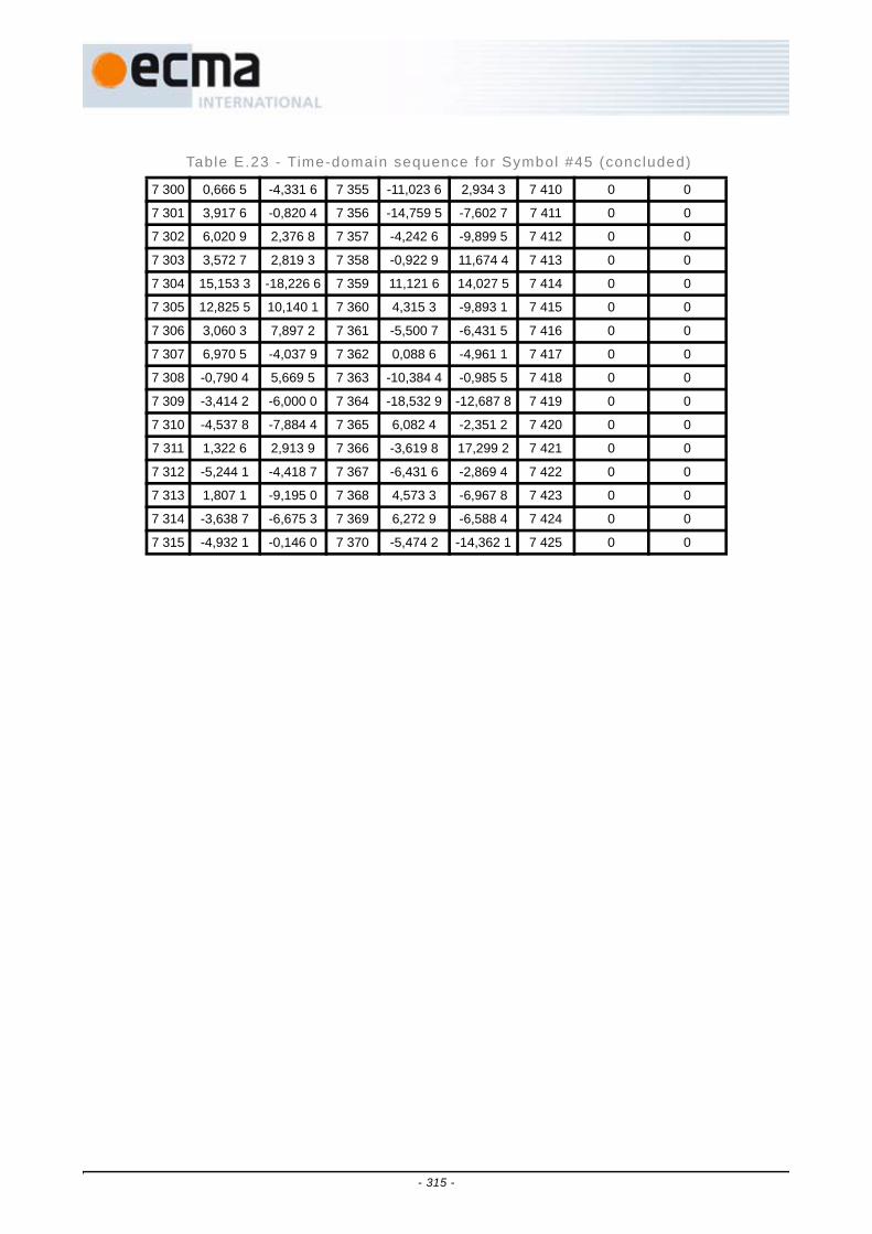
7 300 0,666 5 -4,331 6 7 355 -11,023 6 2,934 3 7 410 0 0
7 301 3,917 6 -0,820 4 7 356 -14,759 5 -7,602 7 7 411 0 0
7 302 6,020 9 2,376 8 7 357 -4,242 6 -9,899 5 7 412 0 0
7 303 3,572 7 2,819 3 7 358 -0,922 9 11,674 4 7 413 0 0
7 304 15,153 3 -18,226 6 7 359 11,121 6 14,027 5 7 414 0 0
7 305 12,825 5 10,140 1 7 360 4,315 3 -9,893 1 7 415 0 0
7 306 3,060 3 7,897 2 7 361 -5,500 7 -6,431 5 7 416 0 0
7 307 6,970 5 -4,037 9 7 362 0,088 6 -4,961 1 7 417 0 0
7 308 -0,790 4 5,669 5 7 363 -10,384 4 -0,985 5 7 418 0 0
7 309 -3,414 2 -6,000 0 7 364 -18,532 9 -12,687 8 7 419 0 0
7 310 -4,537 8 -7,884 4 7 365 6,082 4 -2,351 2 7 420 0 0
7 311 1,322 6 2,913 9 7 366 -3,619 8 17,299 2 7 421 0 0
7 312 -5,244 1 -4,418 7 7 367 -6,431 6 -2,869 4 7 422 0 0
7 313 1,807 1 -9,195 0 7 368 4,573 3 -6,967 8 7 423 0 0
7 314 -3,638 7 -6,675 3 7 369 6,272 9 -6,588 4 7 424 0 0
7 315 -4,932 1 -0,146 0 7 370 -5,474 2 -14,362 1 7 425 0 0
Table E.23 - Time-domain sequence for Symbol #45 (concluded)
- 315 -

Table E.24 - Time-domain sequence for Symbol #46 # Real Imag # Real Imag # Real Imag
7 426 1,414 2 4,242 6 7 481 -3,834 8 -3,796 5 7 536 9,755 2 1,027 2
7 427 -6,435 8 -9,028 4 7 482 1,074 4 10,047 9 7 537 8,871 6 -6,019 2
7 428 5,495 5 9,932 9 7 483 -5,357 4 5,845 6 7 538 6,000 0 0,585 8
7 429 -19,194 0 -15,610 0 7 484 8,084 4 5,677 3 7 539 -8,063 4 1,377 0
7 430 -3,981 1 6,426 2 7 485 -9,459 4 -4,531 4 7 540 -0,109 1 -10,625 4
7 431 2,761 1 8,677 6 7 486 -11,239 5 4,137 8 7 541 12,721 2 8,684 4
7 432 8,698 3 1,615 6 7 487 9,880 1 11,943 3 7 542 -0,301 2 -5,083 9
7 433 11,938 7 0,680 4 7 488 -2,326 7 -8,914 4 7 543 3,328 7 -20,526 5
7 434 6,262 0 -2,386 9 7 489 1,566 9 -5,206 3 7 544 7,884 4 -4,707 8
7 435 0,501 3 -9,205 5 7 490 -4,242 6 1,414 2 7 545 -1,026 7 5,264 3
7 436 12,076 9 -5,979 9 7 491 7,314 6 -5,185 0 7 546 0,440 3 -4,734 2
7 437 12,281 4 8,642 4 7 492 -5,569 1 -4,743 1 7 547 5,437 5 5,228 4
7 438 5,905 8 11,032 5 7 493 2,351 9 1,903 6 7 548 -9,197 0 -15,966 4
7 439 -3,433 7 0,869 5 7 494 -2,428 6 -2,946 0 7 549 16,165 3 2,517 2
7 440 2,528 0 3,348 8 7 495 -16,457 9 9,462 1 7 550 0,930 9 -2,570 1
7 441 9,155 5 13,941 2 7 496 -3,206 5 19,658 2 7 551 -1,661 1 10,175 6
7 442 4,828 4 1,414 2 7 497 -1,087 8 -0,993 1 7 552 -20,493 3 -6,448 3
7 443 -4,853 5 -1,330 3 7 498 2,566 5 -7,613 1 7 553 0,305 1 -11,027 3
7 444 2,773 1 -1,944 1 7 499 -7,234 1 -3,672 4 7 554 0 0
7 445 -8,257 9 2,807 1 7 500 -2,978 9 -16,209 1 7 555 0 0
7 446 13,072 4 1,112 2 7 501 9,234 6 -4,610 8 7 556 0 0
7 447 -4,393 6 2,512 6 7 502 -1,457 4 2,839 7 7 557 0 0
7 448 0,467 6 -7,298 0 7 503 -1,259 9 10,557 1 7 558 0 0
7 449 13,910 7 -2,086 3 7 504 11,255 1 -3,159 8 7 559 0 0
7 450 -4,781 8 11,718 3 7 505 8,555 5 6,820 4 7 560 0 0
7 451 5,256 2 -15,161 4 7 506 0,828 4 1,414 2 7 561 0 0
7 452 -5,857 3 -4,996 3 7 507 4,549 3 6,405 3 7 562 0 0
7 453 -0,755 8 -8,705 9 7 508 7,140 5 14,528 6 7 563 0 0
7 454 -6,811 6 -6,063 7 7 509 -4,886 2 5,088 7 7 564 0 0
7 455 1,482 9 8,926 1 7 510 -6,889 8 -3,492 2 7 565 0 0
7 456 3,699 0 -1,114 2 7 511 -4,581 5 -10,258 0 7 566 0 0
7 457 8,590 4 5,370 7 7 512 2,719 0 16,549 2 7 567 0 0
7 458 -4,242 6 -1,414 2 7 513 -5,992 5 -1,532 0 7 568 0 0
7 459 0,587 2 -15,766 6 7 514 -13,703 5 5,595 4 7 569 0 0
7 460 -7,358 5 -6,906 8 7 515 16,832 1 11,552 9 7 570 0 0
7 461 -0,998 7 3,602 5 7 516 1,235 8 5,019 6 7 571 0 0
7 462 -6,472 5 -3,636 4 7 517 -1,696 3 13,414 4 7 572 0 0
7 463 -1,596 0 -1,675 2 7 518 9,120 2 5,466 5 7 573 0 0
7 464 3,882 6 -13,814 4 7 519 2,032 0 7,299 9 7 574 0 0
- 316 -

7 465 -4,331 6 0,666 5 7 520 2,934 3 -11,023 6 7 575 0 0
7 466 -0,820 4 3,917 6 7 521 -7,602 7 -14,759 5 7 576 0 0
7 467 2,376 8 6,020 9 7 522 -9,899 5 -4,242 6 7 577 0 0
7 468 2,819 3 3,572 7 7 523 11,674 4 -0,922 9 7 578 0 0
7 469 -18,226 6 15,153 3 7 524 14,027 5 11,121 6 7 579 0 0
7 470 10,140 1 12,825 5 7 525 -9,893 1 4,315 3 7 580 0 0
7 471 7,897 2 3,060 3 7 526 -6,431 5 -5,500 7 7 581 0 0
7 472 -4,037 9 6,970 5 7 527 -4,961 1 0,088 6 7 582 0 0
7 473 5,669 5 -0,790 4 7 528 -0,985 5 -10,384 4 7 583 0 0
7 474 -6,000 0 -3,414 2 7 529 -12,687 8 -18,532 9 7 584 0 0
7 475 -7,884 4 -4,537 8 7 530 -2,351 2 6,082 4 7 585 0 0
7 476 2,913 9 1,322 6 7 531 17,299 2 -3,619 8 7 586 0 0
7 477 -4,418 7 -5,244 1 7 532 -2,869 4 -6,431 6 7 587 0 0
7 478 -9,195 0 1,807 1 7 533 -6,967 8 4,573 3 7 588 0 0
7 479 -6,675 3 -3,638 7 7 534 -6,588 4 6,272 9 7 589 0 0
7 480 -0,146 0 -4,932 1 7 535 -14,362 1 -5,474 2 7 590 0 0
Table E.24 - Time-domain sequence for Symbol #46 (concluded)
- 317 -

Table E.25 - Time-domain sequence for Symbol #47 # Real Imag # Real Imag # Real Imag
7 591 -2,828 4 7,071 1 7 646 9,412 6 -3,001 5 7 701 2,792 3 6,664 4
7 592 13,942 1 15,995 9 7 647 -3,826 8 -13,274 5 7 702 -2,690 3 3,685 6
7 593 -3,770 3 7,247 1 7 648 10,311 4 4,988 3 7 703 -2,828 4 -7,656 9
7 594 -8,667 5 4,394 4 7 649 4,213 7 0,698 8 7 704 5,801 3 -7,785 2
7 595 1,018 2 -8,417 5 7 650 -3,321 9 -0,654 9 7 705 -3,265 8 -6,050 7
7 596 -15,391 4 -10,500 5 7 651 -0,003 2 -0,150 0 7 706 -5,786 8 -7,789 5
7 597 -6,892 7 -1,794 0 7 652 -8,007 1 -16,095 5 7 707 6,347 7 -4,899 1
7 598 7,855 7 -13,852 8 7 653 0,146 0 -0,432 0 7 708 0,130 1 4,234 4
7 599 0,600 6 0,927 2 7 654 -4,996 5 -9,681 3 7 709 3,551 6 5,145 0
7 600 -2,168 3 -5,875 6 7 655 -8,485 3 4,242 6 7 710 -1,367 9 -3,590 6
7 601 6,929 2 -10,323 7 7 656 -6,264 9 1,440 3 7 711 3,826 8 -1,553 9
7 602 8,901 0 4,398 6 7 657 3,330 3 -0,053 7 7 712 1,223 9 -1,936 5
7 603 -8,311 2 -4,383 9 7 658 -22,469 8 4,935 2 7 713 -7,759 0 1,625 4
7 604 -11,837 7 -14,374 7 7 659 -14,176 2 -0,358 7 7 714 -15,778 3 -9,688 9
7 605 2,692 7 -3,480 3 7 660 19,165 1 1,181 0 7 715 1,339 6 -1,169 6
7 606 1,182 3 -13,477 7 7 661 -9,318 6 6,860 8 7 716 -9,434 5 0,693 8
7 607 -8,000 0 -6,343 1 7 662 -2,012 3 15,253 2 7 717 -3,131 5 -3,700 0
7 608 12,714 8 -4,106 5 7 663 3,399 4 9,214 9 7 718 11,143 9 6,910 9
7 609 -1,397 7 4,705 8 7 664 -4,153 5 -0,388 8 7 719 0 0
7 610 6,065 9 6,603 0 7 665 14,636 4 -1,210 4 7 720 0 0
7 611 -6,854 3 -27,578 2 7 666 6,210 9 -5,901 8 7 721 0 0
7 612 -14,104 0 -5,184 3 7 667 -1,743 5 -5,586 5 7 722 0 0
7 613 8,104 4 -9,183 7 7 668 -4,628 2 -11,018 4 7 723 0 0
7 614 8,977 7 15,276 2 7 669 1,643 4 3,752 4 7 724 0 0
7 615 9,238 8 -2,171 2 7 670 -0,879 3 6,644 8 7 725 0 0
7 616 4,299 0 1,141 5 7 671 8,000 0 17,656 9 7 726 0 0
7 617 6,518 8 1,177 8 7 672 -1,048 1 -5,358 8 7 727 0 0
7 618 -8,830 6 -7,269 0 7 673 9,241 6 -2,598 5 7 728 0 0
7 619 0,253 8 10,925 3 7 674 -3,872 4 9,982 1 7 729 0 0
7 620 13,031 1 12,952 5 7 675 -0,426 7 -1,485 7 7 730 0 0
7 621 9,576 4 6,168 2 7 676 13,886 0 16,638 4 7 731 0 0
7 622 -4,710 8 -6,844 4 7 677 -7,503 2 -3,576 7 7 732 0 0
7 623 -2,828 4 7,071 1 7 678 -7,224 4 0,391 5 7 733 0 0
7 624 -3,486 8 0,647 4 7 679 -9,238 8 11,342 8 7 734 0 0
76 25 -7,926 9 6,738 8 7 680 6,191 6 5,363 4 7 735 0 0
7 626 -9,678 8 -3,599 7 7 681 2,675 0 -5,337 2 7 736 0 0
7 627 -4,182 9 -0,141 2 7 682 -4,284 1 4,997 4 7 737 0 0
7 628 1,990 7 -8,022 1 7 683 -3,247 0 16,051 1 7 738 0 0
7 629 1,979 4 3,184 3 7 684 1,006 1 5,160 1 7 739 0 0
- 318 -

7 630 1,387 0 -10,543 2 7 685 13,230 7 -5,139 5 7 740 0 0
7 631 -9,074 0 13,849 0 7 686 4,980 1 -6,789 1 7 741 0 0
7 632 2,842 5 -5,627 2 7 687 -2,828 4 4,242 6 7 742 0 0
7 633 24,599 7 1,349 0 7 688 -0,463 3 5,520 2 7 743 0 0
7 634 -1,949 9 12,112 8 7 689 -9,934 4 -4,705 9 7 744 0 0
7 635 -2,915 8 -3,086 3 7 690 1,180 3 -4,362 5 7 745 0 0
7 636 14,100 4 4,527 1 7 691 -0,315 9 -7,366 9 7 746 0 0
7 637 8,363 6 -11,833 2 7 692 -0,394 6 9,453 7 7 747 0 0
7 638 -9,795 6 15,221 6 7 693 2,662 5 8,366 2 7 748 0 0
7 639 -2,828 4 -3,656 9 7 694 -1,889 5 4,396 9 7 749 0 0
7 640 -4,334 0 -2,023 7 7 695 5,074 0 4,293 2 7 750 0 0
7 641 -14,963 1 2,717 1 7 696 19,219 6 -1,994 6 7 751 0 0
7 642 11,585 8 0,289 5 7 697 -0,500 2 4,020 3 7 752 0 0
7 643 7,276 4 -6,321 3 7 698 -3,931 1 -8,446 7 7 753 0 0
7 644 -5,638 6 2,651 9 7 699 3,313 6 -1,286 4 7 754 0 0
7 645 -5,269 7 -1,001 9 7 700 -3,246 1 7,702 6 7 755 0 0
Table E.25 - Time-domain sequence for Symbol #47 (concluded)
- 319 -

Table E.26 - Time-domain sequence for Symbol #48 # Real Imag # Real Imag # Real Imag
7 756 -7,071 1 2,828 4 7 811 3,001 5 -9,412 6 7 866 -6,664 4 -2,792 3
7 757 -15,995 9 -13,942 1 7 812 13,274 5 3,826 8 7 867 -3,685 6 2,690 3
7 758 -7,247 1 3,770 3 7 813 -4,988 3 -10,311 4 7 868 7,656 9 2,828 4
7 759 -4,394 4 8,667 5 7 814 -0,698 8 -4,213 7 7 869 7,785 2 -5,801 3
7 760 8,417 5 -1,018 2 7 815 0,654 9 3,321 9 7 870 6,050 7 3,265 8
7 761 10,500 5 15,391 4 7 816 0,150 0 0,003 2 7 871 7,789 5 5,786 8
7 762 1,794 0 6,892 7 7 817 16,095 5 8,007 1 7 872 4,899 1 -6,347 7
7 763 13,852 8 -7,855 7 7 818 0,432 0 -0,146 0 7 873 -4,234 4 -0,130 1
7 764 -0,927 2 -0,600 6 7 819 9,681 3 4,996 5 7 874 -5,145 0 -3,551 6
7 765 5,875 6 2,168 3 7 820 -4,242 6 8,485 3 7 875 3,590 6 1,367 9
7 766 10,323 7 -6,929 2 7 821 -1,440 3 6,264 9 7 876 1,553 9 -3,826 8
7 767 -4,398 6 -8,901 0 7 822 0,053 7 -3,330 3 7 877 1,936 5 -1,223 9
7 768 4,383 9 8,311 2 7 823 -4,935 2 22,469 8 7 878 -1,625 4 7,759 0
7 769 14,374 7 11,837 7 7 824 0,358 7 14,176 2 7 879 9,688 9 15,778 3
7 770 3,480 3 -2,692 7 7 825 -1,181 0 -19,165 1 7 880 1,169 6 -1,339 6
7 771 13,477 7 -1,182 3 7 826 -6,860 8 9,318 6 7 881 -0,693 8 9,434 5
7 772 6,343 1 8,000 0 7 827 -15,253 2 2,012 3 7 882 3,700 0 3,131 5
7 773 4,106 5 -12,714 8 7 828 -9,214 9 -3,399 4 7 883 -6,910 9 -11,143 9
7 774 -4,705 8 1,397 7 7 829 0,388 8 4,153 5 7 884 0 0
7 775 -6,603 0 -6,065 9 7 830 1,210 4 -14,636 4 7 885 0 0
7 776 27,578 2 6,854 3 7 831 5,901 8 -6,210 9 7 886 0 0
7 777 5,184 3 14,104 0 7 832 5,586 5 1,743 5 7 887 0 0
7 778 9,183 7 -8,104 4 7 833 11,018 4 4,628 2 7 888 0 0
7 779 -15,276 2 -8,977 7 7 834 -3,752 4 -1,643 4 7 889 0 0
7 780 2,171 2 -9,238 8 7 835 -6,644 8 0,879 3 7 890 0 0
7 781 -1,141 5 -4,299 0 7 836 -17,656 9 -8,000 0 7 891 0 0
7 782 -1,177 8 -6,518 8 7 837 5,358 8 1,048 1 7 892 0 0
7 783 7,269 0 8,830 6 7 838 2,598 5 -9,241 6 7 893 0 0
7 784 -10,925 3 -0,253 8 7 839 -9,982 1 3,872 4 7 894 0 0
7 785 -12,952 5 -13,031 1 7 840 1,485 7 0,426 7 7 895 0 0
7 786 -6,168 2 -9,576 4 7 841 -16,638 4 -13,886 0 7 896 0 0
7 787 6,844 4 4,710 8 7 842 3,576 7 7,503 2 7 897 0 0
7 788 -7,071 1 2,828 4 7 843 -0,391 5 7,224 4 7 898 0 0
7 789 -0,647 4 3,486 8 7 844 -11,342 8 9,238 8 7 899 0 0
7 790 -6,738 8 7,926 9 7 845 -5,363 4 -6,191 6 7 900 0 0
7 791 3,599 7 9,678 8 7 846 5,337 2 -2,675 0 7 901 0 0
7 792 0,141 2 4,182 9 7 847 -4,997 4 4,284 1 7 902 0 0
7 793 8,022 1 -1,990 7 7 848 -16,051 1 3,247 0 7 903 0 0
7 794 -3,184 3 -1,979 4 7 849 -5,160 1 -1,006 1 7 904 0 0
- 320 -

7 795 10,543 2 -1,387 0 7 850 5,139 5 -13,230 7 7 905 0 0
7 796 -13,849 0 9,074 0 7 851 6,789 1 -4,980 1 7 906 0 0
7 797 5,627 2 -2,842 5 7 852 -4,242 6 2,828 4 7 907 0 0
7 798 -1,349 0 -24,599 7 7 853 -5,520 2 0,463 3 7 908 0 0
7 799 -12,112 8 1,949 9 7 854 4,705 9 9,934 4 7 909 0 0
7 800 3,086 3 2,915 8 7 855 4,362 5 -1,180 3 7 910 0 0
7 801 -4,527 1 -14,100 4 7 856 7,366 9 0,315 9 7 911 0 0
7 802 11,833 2 -8,363 6 7 857 -9,453 7 0,394 6 7 912 0 0
7 803 -15,221 6 9,795 6 7 858 -8,366 2 -2,662 5 7 913 0 0
7 804 3,656 9 2,828 4 7 859 -4,396 9 1,889 5 7 914 0 0
7 805 2,023 7 4,334 0 7 860 -4,293 2 -5,074 0 7 915 0 0
7 806 -2,717 1 14,963 1 7 861 1,994 6 -19,219 6 7 916 0 0
7 807 -0,289 5 -11,585 8 7 862 -4,020 3 0,500 2 7 917 0 0
7 808 6,321 3 -7,276 4 7 863 8,446 7 3,931 1 7 918 0 0
7 809 -2,651 9 5,638 6 7 864 1,286 4 -3,313 6 7 919 0 0
7 810 1,001 9 5,269 7 7 865 -7,702 6 3,246 1 7 920 0 0
Table E.26 - Time-domain sequence for Symbol #48 (concluded)
- 321 -

- 322 -

Annex F(informative)
Recommended out-of-band emission limitsTable F.1 defines recommended out-of-band emission limits when close proximity between UWB devices andcellular and GPS downlink devices is required. The emission limits are specified for average power andexclude possible narrowband spectrum spikes or spurs. The following parameters were assumed in thederivation of the limits recommended in this Clause:
1. Device separation of 60 cm.
2. Noise figure of 7 dB for cellular and 3,5 dB for GPS, respectively.
3. Allowed noise increase of 1 dB for cellular and 0,5 dB for GPS, respectively.
4. Victim antenna gain of −3 dBi.
5. Free space path loss model (f equals to lower limit of the victim receiver band).
Table F.1 - Recommended out-of-band emission l imi ts
Frequency Band(MHz)
Recommended Emission Limits(dBm/MHz)
869 - 894 -83,3
925 - 960 -82,5
1 570 - 1 581 -84,7
1 805 - 1 880 -76,8
1 930 - 1 990 -76,2
2 110 - 2 170 -75,4
- 323 -

- 324 -

Annex G(informative)
Range measurement calculations
The MAC sublayer and the PHY layer can do two-way time transfer range measurement with remote devices.These measurements result in timing data, which needs further processing. This Annex describes twocalculations that may be performed:
• Distance calculation
• Distance uncertainty
These calculations are shown assuming a 4 224 MHz clock.
G.1 Calculate distance for a single measurement
The MAC entity reports four values per measurement:
• T1c = corrected RM1 send time
• R1c = corrected RM1 receive time
• T2c = corrected RM2 send time
• R2c = corrected RM2 receive time
These are 32-bit numbers, in units of 4 224 MHz clock periods.
T1c and R2c are measured from the same timer in the local DEV1.
R1c and T2c are measured from the same timer in the remote DEV2.
The round trip delay is T1c-R2c. The delay through DEV2 is R1c-T2c.
Subtracting the DEV2 delay from the round trip delay yields two flight times.
Therefore: Flight Time = ½((R2c-T1c)-(T2c-R1c)) in units of 4 224 MHz cycles.
The distance = Flight Time x (c / 4 224 MHz), where c = speed of light.
c / 4 224 MHz = 70,975 4 mm, ~71mm.
G.2 Calculate distance uncertainty
There are several sources of uncertainty or error in range time measurements:
• Noise
• Multipath effects
• Calibration delay constant accuracy (pRangingTtransmitDelay & pRangingReceiveDelay)
• Calibration delay constant precision
- 325 -

• Timer clock resolution
• Timer clock accuracy
• Timer clock differences between the two devices
• Relative motion
G.2.1 Noise effectsThe most likely effects of noise are twofold:
• Cause bit errors that prevent the intact deliver of ranging measurement frames RM1 or RM2(the ACK for RM1).
• Cause variance in the accuracy of the receiving PHYs’ detection of the ranging reference signal.
If frames are not delivered, there will be incomplete sets of range measurement data.
If there are multiple measurements, the DME can use intact measurements to interpolatewhich measurements are missing, and discard the corresponding data. For example, if anRM2 frame was not received intact, there will be a missing R2c value.
Noise can cause jitter in the detection of timing references. This jitter will be reported inmultiples of the receiving PHYs’ timing clock. For example, if noise causes a timing referenceto be detected one clock early, and the timer is running at 1 056 MHz (an optional value), thatwill result in a 14,2 cm error; 1 056 MHz = ¼ of 4 224 MHz, and the error is halved in the 1distance calculation.
The DME can attempt to improve distance measurement accuracy in the presence of noiseby making repeated measurements and averaging the results.
G.2.2 Multipath effectsThe line-of-sight signal will be the first to arrive, yielding the correct range. However, signalswill bounce, and non-line-of-sight signals may exceed the amplitude of the line-of-sightsignal.
To avoid detecting multiple peaks, the PHY should employ some means to respond to the firstpeak, and ignore others shortly after.
If the PHY responds first to a non-line-of-sight signal, that signal will have taken a longerflight path, and will therefore take longer to arrive. The perceived flight time will be longer,and the computed distance will track. Therefore, in the presence of multipath, the calculatedrange distance measurements will be upper bounds on the true distance.
G.2.3 Calibration delay constant accuracy & precisionThe delays in the PHY are defined as:
pRangingTransmitDelay = the time from the generation of the reference signal, whichtriggers the RTIMER capture (e.g. T1 or T2), to the time this signal reaches the deviceantenna. T1c = T1 + pRangingTransmitDelay.
pRangingReceiveDelay = the time from the arrival of the reference signal at the antenna tothe time this signal is first detected in the PHY, triggering the RTIMER clock capture (e.g.R1 or R2). R1c = R1 - pRangingReceiveDelay.
These constants are 16-bit unsigned integer values, in units of 4 224 MHz clock periods.
There are pairs of these constants for each PHY. Therefore, each of these four constants cancontribute two errors:
• Inaccuracy, as specified by the manufacturer
• Quantization error (in the order of one 4 224 MHz cycle, 237 psec)
- 326 -

NOTEThe delays may only be accurately measured and characterized from inside the PHY DSP to the chipleads. The delays from the chip pins to the antenna may vary by a small amount, depending on trace orcable lengths. These external transmission delays may have to be estimated.
Since each delay is uncorrelated with the others, the expected quantization error is the RMSsum of four +/- half bit errors.
G.2.4 Timer clock resolutionThe distance measure is limited by the resolution of the timers used for measuring time offlight. The implemented clock resolution generates simple quantization errors.
The PHY specification allows options in the PHY ranging timer resolution:
• 528 MHz, 56,8 cm, minimum if ranging is implemented
• 1 056 MHz, 28,4 cm, optional
• 2 112 MHz, 14,2 cm, optional
• 4 224 MHz, 7,1 cm, maximum option
The local PHY reports these options to the MAC via a PLME static parameter. The DME canquery these via the PLME-GET.request primitive.
The remote PHY reports this same RangingSupported static parameter to the remote MACsublayer, which delivers it to the local MAC sublayer by the RMR frame. The local MACsublayer in turn reports this value to the DME via the MLME-RANGE-MEASUREMENT.confirm primitive.
Therefore, either PHY can contribute quantization error. The expected value for eithercontribution is half of the quantization distance (e.g. 3,6 – 28,4 cm). The expected value forthe combination of these errors is the RMS sum of the two contributions (e.g. 5 – 40 cm),since the clocks are not synchronized and therefore uncorrelated.
G.2.5 Timer clock accuracyThe PHY specification requires that the clock frequency must be within 20 ppm. Withoutcorrection, deviation by either clock generates time measurement errors. These errors areproportionate to two factors:
• The extent of inaccuracy (for each PHY clock)
• The time taken to perform each two-way time transfer measurement
The local PHY reports the manufacturer-specified timer clock tolerance to the MAC via aPLME static parameter. The units are in ppm (parts per million). The DME can query this viathe PLME-GET.request primitive.
The remote PHY reports this same pClockAccuracy static parameter to the remote MACsublayer, which delivers it to the local MAC sublayer by the RMR frame. The local MACsublayer in turn reports this value to the DME via the MLME-RANGE-MEASUREMENT.confirm primitive. These values do not report the actual clock frequencyerrors; they report tolerances.
Each timer clock inaccuracy contributes error accumulated over the time it runs. The DEV1clock should run approximately 23,4 s + one flight time; the DEV2 clock should runapproximately 23,4 s – one flight time. 23,4 s = 1 preamble (10,0) + frame (~3,4) + SIFS(10,0).
23,4 s = 98 841 cycles of 4 224 MHz. 20 ppm of 98 841 is approximately two clock cycles.Therefore, either PHY clock can generate errors of +/- 2 clocks; the maximum error could bejust under 4 clock cycles. Because these effects are halved in the distance calculation, themaximum possible error would be 14 cm (28/2) if the clocks both err in the same direction.
- 327 -

The expected value of this error depends on the actual statistics of the crystals commonlyused in these devices. If the clock errors are randomly distributed, it will be lower (Gaussianaround zero) because positive and negative errors offset.
G.2.6 Clock frequency differencesIf the two PHY clocks are offset in the same direction, the errors will add, as describedabove. If they are in the opposite directions, they will cancel; the calculated result will be thesame as that resulting from both clocks having the same offset as the average of theiroffsets.
It is possible using repeated measurements to detect and correct for differences between thelocal and the remote clock frequencies. However, the local DEV1 has no way of knowingwhether its own clock or the remote clock is actually more accurate. (It only has thetolerances.) This operation would be useful only if the local clock is very tight (e.g. 5 ppm)and the remote clock is very loose (e.g. 40 ppm).
G.2.7 Clock frequency detectionIf the local device wants to normalize measurements to its own clock, it can detect andcorrect for frequency offset differences between its local clock and the remote clock.
Detection of the clock frequency offset between the local clock and remote clock can besimple if there is little noise induced jitter. Consider the case of executing a set of Nconsecutive ranging measurements (e.g. MLME-RANGE-MEASUREMENT.request(DestAddr, N) ). The MAC sublayer will return N sets of timer valuesusing MLME-RANGE-MEASUREMENT.confirm. Assuming the clock error is constant, thatclock error (in 4 224 MHz cycles) can be approximated by:
[(Nth T1c)-(1st T1c)] – [(Nth R1c)-(1st R1c)]
or
[(Nth T2c)-(1st T2c)] – [(Nth R2c)-(1st R2c)]
Working backwards, the relative error in any one measurement would be:
([(Nth T1c)-(1st T1c)] – [(Nth R1c)-(1st R1c)])/(2(N-1)).
For example, if N = 4, [(4th T1c)-(1st T1c)] should be approximately 2(4-1) x 23,4 s = 140,4 s,or 593 050 4 224 MHz clock periods. If the remote clock differs by 20 ppm, the cumulativeerror over 4 consecutive measurements would be approximately +/- 24 clock periods or 4clocks per measurement, +/- 28,4 cm.
If noise induced jitter is large, the repeated measurements might need to be processed to fitstraight lines through the timing data, then process as shown in the previous paragraph.
G.2.8 Motion effectsIf motion were to effect a single two-way time transfer measurement as described in thisstandard, the relative motion of the two devices would need to meet or exceed a clockwavelength in the measurement time of 23,4 s. Using the most precise clock, 4 224 MHz, therelative motion would have to be (71 mm / 23,4 s) = (71 km / 23,4 s) ~ 3,0 km/s ~ Mach 10!Therefore, for practical purposes, relative motion will have no measurable effect.
- 328 -

Annex H(informative)
Bibliography
[H1] "Guidelines for use of a 48-bit Extended Unique Identifier (EUI-48™)",
http://standards.ieee.org/regauth/oui/tutorials/EUI48.html
[H2] IEEE STD 802.3 -2005 IEEE Standard for Information technology - Telecommunications and informationexchange between systems- Local and metropolitan area networks- Part 3: Carrier sense multiple accesswith collision detection (CSMA/CD) access method and physical layer specifications.
[H3] ISO/IEC 7498-1:1994, Information Technology-Open Systems Interconnection-Basic Reference Model:The Basic Model.
[H4] IETF RFC 4086, Randomness Requirements for Security, June 2005
[H5] IETF RFC 3610, Counter with CBC-MAC (CCM), September 2003
- 329 -

- 330 -


![Resolutions to Comments #120, 123, 124, 125, 135, …...[A PHY and MAC proposal for 802.15.4m] Abstract: [This document presents a proposal on the PHY and MAC system design for 802.15.4m]](https://static.documents.pub/doc/80x56/5f371c4791aa2a2bff69150a/resolutions-to-comments-120-123-124-125-135-a-phy-and-mac-proposal-for.jpg)


