IEEE TRANSACTIONS ON PLASMA SCIENCE, VOL. PS-8, NO. 3, SEPTEMBER 1980 High Repetition Rate Miniature Triggered Spark Switch M. F. ROSE AND M. T. GLANCY Abstract-A miniature triggered spark switch designed to operate at high repetition rates has been constructed. The device, along with asso- ciated triggered circuitry, has been incorporated into a simple LC gen- erator which produces an oscillatory discharge at a frequency of 150 MHz. The switch is operated in the pressure range 760 torr-2.6 X i03 tor using commercial dry nitrogen as the working gas. Both brass (70/30) and aluminum (99.95 percent) electrodes were investigated for repetition frequencies as high as 20 kHz and for gas flow rates as high as 8 cm3/s. The effect of repetition rate on switch jitter and switch breakdown voltage is presented and discussed in terms of gas pressure and flow rate. INTRODUCTION IGH REPETITION rate switching in the region greater than 10 kHz can be accomplished by thyratrons and, in some cases, vacuum gaps. Unfortunately, these techniques often suffer from jitter or inductance problems which are unacceptable in high frequency Hertzian generators. A quenching spark gap, however, appears to be one of the simplest and most efficient devices for this purpose, if fast turn on and low losses are desirable. The general idea of a quenching switch is one which has a large (>10) Ald ratio, and additionally, a small value of d. The quenching action is based upon the fact that small plasma volumes can maintain good electrical conductivity in the small gap spacing very soon after initiation of the switch process. After the driving potential has been removed, the small plasma volume can quickly recover. Excess thermal energy associated with the gap dissipation can be transferred to the switch electrode surfaces or blown from the system with sufficient gas flow. It is difficult, however, to provide an adequate trigger mechanism to take advantage of the high repetition rate in applications which demand precision pulse spacing. Single stage switches of this type have gap spac- ings no more than a few hundred microns which make it diffi- cult to design and implement a "third electrode" trigger of the trigatron-type. The purpose of this paper is to describe the operating characteristics of a simple high repetition rate quenching spark switch under gas flow when configured as part of a small Hertzian generator of the type described by Moran [1] and by Glancy and Rose [2]. In addition, this generator is triggered by superimposing a fast transient on the normal RC-charge waveform. Manuscript received February 4, 1980; revised April 3, 1980. This work was supported in part by the Defense Advance Projects Research Agency through the Naval Air System Command. The authors are with the Naval Surface Weapons Center, Dahlgren, VA 22448. DIELECTRIC Fig. 1. Cross-sectional view of oscillator and switch. Fig. 2. Schematic of the gas pressure and flow system. EXPERIMENTAL Fig. 1 shows a cross-sectional view of the oscillator and the switch. The device has circular symmetry and is held together using several nylon bolts. The pressure collar is made of Plexi- glas and is sealed to the switch electrodes via ORings. The electrodes are 1.02 cm in diameter, giving an Ald ratio of approximately 50. In addition, the electrodes are removable for examination of wear and other electrode effects [21. For our experiments, we have investigated both brass (70/30) and aluminum (99.95 percent) electrodes with 100-,m gap spac- ing. The initial electrode preparation is described in [2]. The electrodes are provided with a gas inlet immediately in the center of one of the switch electrodes, and gas flow outlet holes located around the periphery of the other electrode. Fig. 2 shows a schematic of the gas flow and pressurization scheme. While we realize that the configuration is probably not optimum from a gas dynamic point of view, it offers mini- mum inductance, a desirable characteristic for our application. U.S. Government work not protected by U.S. copyright 139
Transcript
IEEE TRANSACTIONS ON PLASMA SCIENCE, VOL. PS-8, NO. 3, SEPTEMBER 1980
High Repetition Rate Miniature TriggeredSpark Switch
M. F. ROSE AND M. T. GLANCY
Abstract-A miniature triggered spark switch designed to operate athigh repetition rates has been constructed. The device, along with asso-ciated triggered circuitry, has been incorporated into a simple LC gen-erator which produces an oscillatory discharge at a frequency of150 MHz. The switch is operated in the pressure range 760 torr-2.6 Xi03 tor using commercial dry nitrogen as the working gas. Both brass(70/30) and aluminum (99.95 percent) electrodes were investigated forrepetition frequencies as high as 20 kHz and for gas flow rates as highas 8 cm3/s. The effect of repetition rate on switch jitter and switchbreakdown voltage is presented and discussed in terms of gas pressureand flow rate.
INTRODUCTIONIGH REPETITION rate switching in the region greaterthan 10 kHz can be accomplished by thyratrons and, in
some cases, vacuum gaps. Unfortunately, these techniquesoften suffer from jitter or inductance problems which areunacceptable in high frequency Hertzian generators. Aquenching spark gap, however, appears to be one of thesimplest and most efficient devices for this purpose, if fastturn on and low losses are desirable. The general idea of aquenching switch is one which has a large (>10) Ald ratio, andadditionally, a small value of d. The quenching action is basedupon the fact that small plasma volumes can maintain goodelectrical conductivity in the small gap spacing very soon afterinitiation of the switch process. After the driving potential hasbeen removed, the small plasma volume can quickly recover.Excess thermal energy associated with the gap dissipation canbe transferred to the switch electrode surfaces or blown fromthe system with sufficient gas flow. It is difficult, however, toprovide an adequate trigger mechanism to take advantage ofthe high repetition rate in applications which demand precisionpulse spacing. Single stage switches of this type have gap spac-ings no more than a few hundred microns which make it diffi-cult to design and implement a "third electrode" trigger of thetrigatron-type. The purpose of this paper is to describe theoperating characteristics of a simple high repetition ratequenching spark switch under gas flow when configured aspart of a small Hertzian generator of the type described byMoran [1] and by Glancy and Rose [2]. In addition, thisgenerator is triggered by superimposing a fast transient on thenormal RC-charge waveform.
Manuscript received February 4, 1980; revised April 3, 1980. Thiswork was supported in part by the Defense Advance Projects ResearchAgency through the Naval Air System Command.The authors are with the Naval Surface Weapons Center, Dahlgren,
VA 22448.
DIELECTRIC
Fig. 1. Cross-sectional view of oscillator and switch.
Fig. 2. Schematic of the gas pressure and flow system.
EXPERIMENTAL
Fig. 1 shows a cross-sectional view of the oscillator and theswitch. The device has circular symmetry and is held togetherusing several nylon bolts. The pressure collar is made of Plexi-glas and is sealed to the switch electrodes via ORings. Theelectrodes are 1.02 cm in diameter, giving an Ald ratio ofapproximately 50. In addition, the electrodes are removablefor examination of wear and other electrode effects [21. Forour experiments, we have investigated both brass (70/30) andaluminum (99.95 percent) electrodes with 100-,m gap spac-ing. The initial electrode preparation is described in [2].The electrodes are provided with a gas inlet immediately in
the center of one of the switch electrodes, and gas flow outletholes located around the periphery of the other electrode.Fig. 2 shows a schematic of the gas flow and pressurizationscheme. While we realize that the configuration is probablynot optimum from a gas dynamic point of view, it offers mini-mum inductance, a desirable characteristic for our application.
U.S. Government work not protected by U.S. copyright
139
IEEE TRANSACTIONS ON PLASMA SCIENCE, VOL. PS-8, NO. 3, SEPTEMBER 1980
la; t'U
Fig. 3. Schematic diagram of the oscillator charging system and triggerarrangements.
The working gas used is commercial dry nitrogen. The highpressure tubing connecting the various components was con-stant diameter, and all components were placed as close tothe switch as possible. A Heiss pressure gauge was used andcalibrated with an accuracy of ±1 psig (51.7 torr). A RateMaster flow meter was used which provided the capability foraccurately measuring flow rates of 0.4 cm3/s. A bleed valvewas used to flush both the oscillator and gas lines prior tooperation.
Fig. 3 illustrates schematically the system used to chargethe oscillator and to provide a reliable trigger. The oscillatorcapacitance C0 (433 pF) is charged through a variable chargingresistor Rc. When the charging voltage on the oscillatorreaches a preset value, the impulse generator (IMP) sends apulse into the oscillator, rapidly overvolting the gap, and caus-ing it to fire in a time short in comparison to the RC-chargetime. The diodes D (Semtech 12500 SCF) are so arranged toprevent the oscillator from discharging through the secondaryof the IMP transformer, or alternatively through the powersupply, so that no energy is wasted from the trigger pulse.The energy stored in the oscillator is "latched" in and candissipate rapidly by firing switch S or slowly leak off throughthe back resistances of the diodes. A Tektronix high voltageprobe (P-6015) was used with a Tektronix 7904 oscilloscopeto provide nanosecond time resolution.The pulser itself is a Velonix model 350 with the output
transformer modified to provide pulses as high as 12 kV intoa matched load. Prior to running, the oscillator surfaces wereground flat and metallurgically polished as described elsewhere[2]. Fig. 4 summarizes the operating characteristics of theexperiment. Fig. 4(a) shows the voltage-time history as pro-vided by the main power supply (top trace) and the output ofthe IMP (lower trace). Fig. 4(b) illustrates the final impulsecharge provided from the trigger generator. Fig. 4(c) illus-trates the repeatability of the trigger system and shows jitter(20 ns). For our purposes, we define jitter as the maximumspread in switch times as integrated over several seconds orseveral hundred events chosen at random. For this experi-ment, we routinely sampled 400 separate trigger events todetermine the distribution, however, the photo shows some50 events. Fig. 4(d) shows the RF envelope for the oscillatoroutput. The system impedance is about 3 QZ which ensures alarge damping constant (Q ~3) and maximum current in thekiloampere range, with the switch itself being the primaryload.
(c) (d)
Fig. 4. Voltage-time traces for the oscillator and switch. (a) Top traceis normal RC charge for osciBator; 500 V/cm, 2 ms/cm. Bottom traceis trigger pulse from IMP; 1000 V/cm, 2 ms/cm. (b) Bottom trace isnormal RC charge for oscillator; 500 V/cm, 0.2 ms/cm. Top traceshows impulse charging of oscillator and overvoltage which occurs asa result of impulse; 500 V/cm, 200 ns/cm. (c) Superposition of 50pulses to ilustrate jitter; 500 V/cm, 10 ns/cm. (d) Output waveformfor oscillator; 200 V/cm, 20 ns/cm.
The value of the charge resistor RC can be chosen such that,at a given frequency, more than 90 percent of the energy isprovided by the main power supply, thereby placing very littlestrain on the pulse generator. In these experiments, however,we did not always operate in this mode, but held RC constant(1.05 MQ2) for convenience.
DISCUSSION
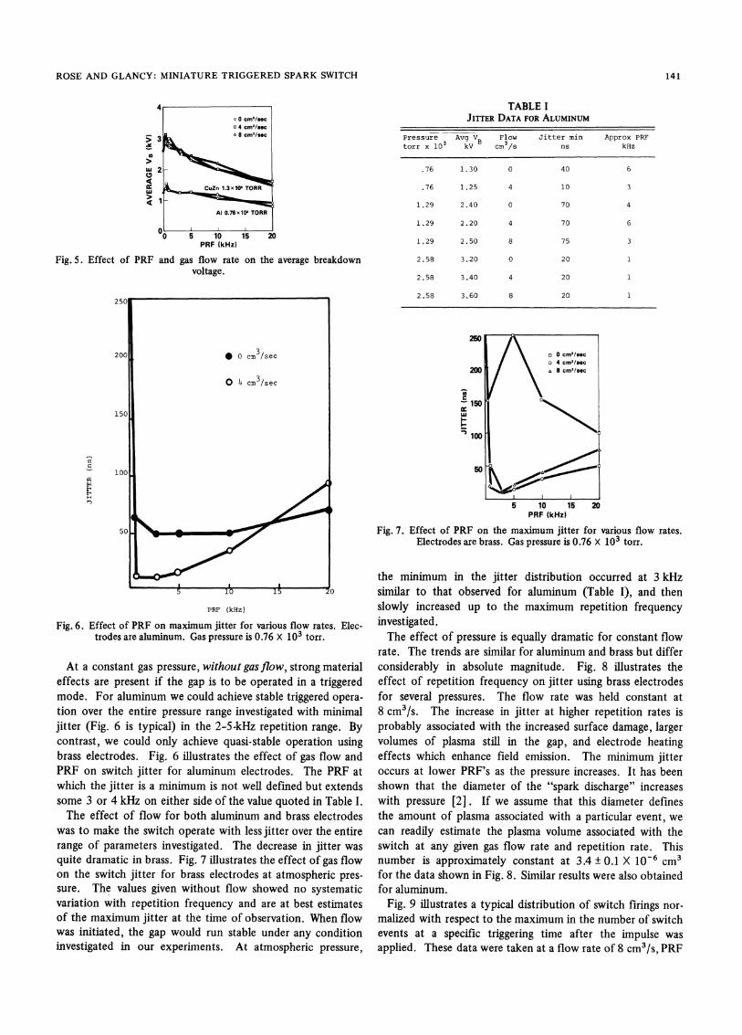
Among the factors which could affect the breakdown volt-age in a system are pulse repetition rate, gas flow rate, gas pres-sure, electrode material, gas species, and time rate of change ofthe trigger pulse. In our experiments, we varied the first fourof these parameters while holding the other factors constant,to a first approximation. For the range of fields investigated(up to 260 kV/cm) varying the electrode material did notappear to influence the breakdown voltage. Slight deviationswere sometimes noted, but these were well within the experi-mental error. The effect of pressure on the static breakdownvoltage is well documented [3] and our results are consistentwith Cookson [4]. However, under impulse charging andflowing gas conditions, the breakdown voltage (typical data inFig. 5) increased up to a value as high as 30 percent greaterthan the static value, and slowly decreases as the pulse repeti-tion frequency (PRF) is increased. At a PRF of 20 kHz, thefiring voltage for the switch has dropped to a value about 23of the static value. The effect of flow was minimal on thebreakdown voltage (over the range investigated) and in generalwas confined to pulse frequencies less than 3 kHz. We attrib-ute this to the multitude of other factors which could beactive in determining the breakdown voltage for the gap (e.g.,particulate matter of a size comparable to the gap spacing,thermal energy deposited in the electrode surface and gas,plasma in the gap due to previous discharge).
140
ROSE AND GLANCY: MINIATURE TRIGGERED SPARK SWITCH
and gas flow rate on the average breakdownvoltage.
PRF (kHz)
Fig. 6. Effect of PRF on maximum jitter for various flow rates. Elec-trodes are aluminum. Gas pressure is 0.76 X 10³ torr.
At a constant gas pressure, without gas flow, strong materialeffects are present if the gap is to be operated in a triggeredmode. For aluminum we could achieve stable triggered opera-tion over the entire pressure range investigated with minimaljitter (Fig. 6 is typical) in the 2-5-kHz repetition range. Bycontrast, we could only achieve quasi-stable operation usingbrass electrodes. Fig. 6 illustrates the effect of gas flow andPRF on switch jitter for aluminum electrodes. The PRF atwhich the jitter is a minimum is not well defined but extendssome 3 or 4 kHz on either side of the value quoted in Table I.
The effect of flow for both aluminum and brass electrodeswas to make the switch operate with less jitter over the entirerange of parameters investigated. The decrease in jitter was
quite dramatic in brass. Fig. 7 illustrates the effect of gas flowon the switch jitter for brass electrodes at atmospheric pres-
sure. The values given without flow showed no systematicvariation with repetition frequency and are at best estimatesof the maximum jitter at the time of observation. When flowwas initiated, the gap would run stable under any conditioninvestigated in our experiments. At atmospheric pressure,
TABLE IJITTER DATA FOR ALUMINUM
Pressure Avg VB Flow Jitter min Approx PRFtorr x 10 3 kV cm3/s ns kHz
.76 1.30 0 40 6
.76 1.25 4 10 3
1.29 2.40 0 70 4
1.29 2.20 4 70 6
1.29 2.50 8 75 3
2.58 3.20 0 20 1
2.58 3.40 4 20 1
2.58 3.60 8 20 1
PRF (kHz)
Fig. 7. Effect of PRF on the maximum jitter for various flow rates.Electrodes are brass. Gas pressure is 0.76 X 10³ torr.
the minimum in the jitter distribution occurred at 3 kHzsimilar to that observed for aluminum (Table I), and thenslowly increased up to the maximum repetition frequencyinvestigated.The effect of pressure is equally dramatic for constant flow
rate. The trends are similar for aluminum and brass but differconsiderably in absolute magnitude. Fig. 8 illustrates theeffect of repetition frequency on jitter using brass electrodesfor several pressures. The flow rate was held constant at8 cm3/s. The increase in jitter at higher repetition rates isprobably associated with the increased surface damage, largervolumes of plasma still in the gap, and electrode heatingeffects which enhance field emission. The minimum jitteroccurs at lower PRF's as the pressure increases. It has beenshown that the diameter of the "spark discharge" increaseswith pressure [2]. If we assume that this diameter definesthe amount of plasma associated with a particular event, wecan readily estimate the plasma volume associated with theswitch at any given gas flow rate and repetition rate. Thisnumber is approximately constant at 3.4 ± 0.1 X 10⁻⁶ cm3for the data shown in Fig. 8. Similar results were also obtainedfor aluminum.
Fig. 9 illustrates a typical distribution of switch firings nor-
malized with respect to the maximum in the number of switchevents at a specific triggering time after the impulse was
applied. These data were taken at a flow rate of 8 cm3/s, PRF
0
wm
F(
Fig. 5. Effect of PRF
141
C_uz
H
IEEE TRANSACTIONS ON PLASMA SCIENCE, VOL. PS-8, NO. 3, SEPTEMBER 1980
II ( ~~~2.6 .10O TORRI
cc 2D 0 uIO
100
0 5 10 15 20PRF (kHz)
Fig. 8. Effect of PRF on maximum switch jitter for constant flow rate(8 cm3/s) for various pressures.
TIME (ns)
Fig. 9. Jitter distribution in brass and aluminum. Pressure 0.76 x 10³torr, flow rate 8 cm3/s, PRF 5 kHz.
of 5 kHz, and atmospheric pressure. The curves representsome 400 individual events, taken at random, over a period ofseveral minutes. The distribution for brass electrodes is ap-
proximately Gaussian, and the extrema agree well with themaximum jitter as observed directly from the oscilloscope.The results for aluminum were complicated, and we attributethis to local defects such as that shown in Fig. 10 which even-
tually grow to such an extent that the gap is effectively shortedout. We did not observe similar failure in brass although run-
ning times of several hours were sometimes involved. In gen-
eral, aluminum failed after some 45 min with a drasticincrease in jitter and a decrease in breakdown voltage, and inall cases a localized damaged area was observed.
Fig. 10. Failure zone on aluminum electrode surface.
SUMMARY
Simple spark switches can be made to operate in a triggeredmode for frequencies as shown as 20 kHz with a maximum of30-percent decrease in the breakdown voltage. In so far as weinvestigated, there is very little effect of materials on the aver-age breakdown voltage of the switch. There are, however,large material effects associated with switch jitter which areprobably due to surface chemistry and contamination of theworking gas by particulate matter, blown from the surfaces.Introduction of gas flow greatly enhances stability and oftenresults in orders of magnitude reduction in switch jitter. Inaddition to the usual effect of gas pressure on the breakdownvoltage, gas pressure also influences switch jitter over theentire range of parameters investigated.
ACKNOWLEDGMENTWe wish to thank C. E. Comford for assistance during the
course of these experiments.
REFERENCES
[1] S. L. Moran, "High repetition rate L-C oscillator," in IEEE Conf.Rec. Thirteenth Pulse Power Modulator Symp., pp. 254-259,1978.
[21 M. T. Glancy and M. F. Rose, "Surface aging in high repetitionrate spark switches with aluminum and brass electrodes," in Proc.Second IEEE Int. Pulsed Power Conf., pp. 301-307, June 1979.
[31 J. D. Cobine, Gaseous Conductors. 1958, pp. 163.[4] A. H. Cookson, "Electrical breakdown for unfform fields in com-
pressed gases," Proc. IEEE, vol. 117, pp. 269-280, Jan. 1970.