19
Before installing and operating this product, please read this manual thoroughly. ENGLISH High Resolution Day & Night IR Camera SCO-2080R User Guide

Before installing and operating this product,please read this manual thoroughly.
ENGLISH
High Resolution Day & Night IR Camera SCO-2080R User Guide

Before operating the camera, confirm the camera model and correct input power voltage. In order to that you can understand this manual thoroughly, we will explain the model description.
nSCO-2080R SERIES •NTSCMODEL •PALMODEL SCO-2080RN SCO-2080RP
nMODEL DESCRIPTION •SCO-2080RX
_
•SIGNALSYSTEM N-->NTSCMODEL P-->PALMODEL
SIGNALSYSTEM
This installation should be made by a qualified service person and should conform to all local codes.
Thelightningflashwithanarrowheadsymbol,withinanequilateraltriangleisintended to alert the user to the presence of uninsulated “dangerous voltage” withintheproduct'senclosurethatmaybeofsufficientmagnitudetoconstitutea risk of electric shock to persons.
Theexclamationpointwithinanequilateraltriangleisintendedtoalerttheuserto the presence of important operating and maintenance (servicing) instructions in the literature accompanying the appliance.
INFORMATION-This equipment has been tested and found to comply with limits for a Class A digital device, pursuant to part 15 of the FCC Rules. These limits are designed to provide reasonable protection against harmful interference when the equipment is operated in a commercial environment. This equipment generates, uses, and can radiate radio frequency energy and, if not installed and used in accordance with the instruction manual, may cause harmful interference to radio communications.Operation of this equipment in a residential area is likely to cause harmful interference in which case the user will be required to correct the interference at his own expense.
WARNING -Changes or modifications not expressly approved by the manufacturer could void the user’s authority to operate the equipment.
WARNING -To prevent electric shock and risk of fire hazards: Do NOT use power sources other than that specified. Do NOT expose this appliance to rain or moisture.

COLOR CCD CAMERA User Guide4 COLOR CCD CAMERA User Guide5
ContentsContents
• Features ……………………………………………………………… 5
• Warnings & cautions ………………………………………………… 6
• Precautions…………………………………………………………… 7
• Components and Accessories ……………………………………… 9
• Overview …………………………………………………………… 9 n Front……………………………………………………………………………… 9…… n Back………………………………………………………………………………10
• Adjust to lens ………………………………………………………… 11 n AjusttoLens’sZOOMandFocus………………………………………………… 11
• Connection …………………………………………………………… 12 n Connectingtoamonitor…………………………………………………………12…… n Connectingtopower… …………………………………………………………13…… n RS-485Communicationcontrol…………………………………………………14… n UsingCoaxialCommunications…………………………………………………15
• Operating Your Camera …………………………………………… 16 n MenuConfiguration………………………………………………………………16…… n MenuSetup………………………………………………………………………16…
•LENS(Adjustingtothebrightnesslevel)…………………………………… 17…… … •EXPOSURE… …………………………………………………………… 18…… … •WhiteBalance(WhiteBal.)………………………………………………… 19…… … •SSDR(SamsungSuperDynamicRange)…………………………………… 20…… … •BACKLIGHT……………………………………………………………… 21…… … •SSNR3…………………………………………………………………… 23…… … •DAY/NIGHT… …………………………………………………………… 24…… … •SPECIAL………………………………………………………………… 26…… … •EXIT……………………………………………………………………… 31
• Troubleshooting ……………………………………………………… 32
• Specifications ………………………………………………………… 33
• Dimension …………………………………………………………… 34
DAY&NIGHT(ICR)
Thiscamerahasa functionthatautomaticallyselectsthemodethatisappropriatefordaytimeornight-timeconditions.TheCOLORmodeoperates indaytimeconditions toprovideoptimumcolors,andBWmodeoperates innight-timeconditions toenhance thedefinitionof theimage.
Outdoor Visibility range 50M
The IR LEDs of the SCO-2080R automaticallyilluminates viewing area in the extreme darkness allowingthecameraalong-rangevisibilityofupto50meters.
IR MODE Function
This functionprevents thesaturationof the imagebytheIRilluminatorsatshortdistance.
IP66 Approved/Dust and RainResistantWithdustandrainresistantdesign,thecameracanbeinstalledoutsideunderbuildingeavesorplaces thatare exposed to the dust and rain.
Ultra High Sensitivity
Thebuilt-inhighsensitivityCOLORCCDproducesaclear imageeven in0Lux(B/W, IR-LEDON)or lowerillumination.
High Resolution
Byadoptingadiagonal6mm(1/3")410,000 (NTSC)pixel, 470,000(PAL)pixelSONYCCD, thecameraproduces clear picturequalitywith ahorizontalresolutionof600TV lines forcolorandahorizontalresolutionof700TVlinesforBWmode.
SSDR (Samsung Super Dynamic Range) ForimageswithhighcontrastbetweenbrightanddarkAreas fromdifficult lighting conditions suchasbacklighting,thiscameraselectivelyilluminatesdarkerAreaswhileretainingthesamelightlevelforbrighterAreastoevenouttheoverallbrightness.
Communication
RS-485, Coaxial communicationmethods aresupported.-RS-485Communications:SAMSUNG-T,SAMSUNG-E,PELCO-P,PELCO-D,VICON,PANASONIC,BOSCH,HONEYWELL
-CoaxialCommunications:PelcoCoaxitron
Miscellaneous Functions
HLC(HighLightCompensation),SENS-UP,FLIP(H/V-REV),D-ZOOM, SHARPNESS,MOTIONDETECTION andPRIVACYfunctionsareprovided.
OSD
Thecamera’sOSDiscomplimentedby18languages.-NTSC:Korean,English,French,Spanish,Japanese,
Portuguese,Taiwanese-PAL :English,French,German,Spanish, Italian,
Chinese,Russian,Czech,Polish,Romanian,Serbian,Swedish,Danish,Turkish,Portuguese
SSNR3 (Samsung Super Noise Reduction) Function
Thehigh-performanceW-VDSPchipeffectivelyremoveslow-lightgainnoiseandghostingtoprovideclear images even in dark environments.
Features

COLOR CCD CAMERA User Guide6 COLOR CCD CAMERA User Guide7
Thisinformationisprovidedtoensureyoursafetyandtopreventanylosses,financialorotherwise.Pleasereaditcarefullyandusetheproductaccordingly.
*Forproductinquiries,pleasecontacttheretailshopwhereyouboughtthecamera.Theuseofequipmentsuchasanaerialladderwhileprovidingafter-salesserviceshallbeatyourexpense.
Ignoring this information may result in deathororseriouspersonalinjuries.
Indicates"NeverAllowed."
Ignoring this information may result in materiallossorpersonalinjuries.
Indicates "NoDisassembling."
SamsungTechwincaresfortheenvironmentatallproductmanufacturingstagestopreservetheenvironment,and is takinganumberof steps toprovidecustomerswithmoreenvironment-friendlyproducts.TheEcomarkrepresentsSamsungTechwin'swill tocreateenvironment-friendlyproducts,andindicatesthattheproductsatisfiestheEURoHSDirective.
Warnings & Cautions
Warning/Attention/Special Mark Messages
Notes•Pleasemakesuretheproductisinstalledappropriateplaceswheresecuredfrom
flood, such as under the eaves, to operate properly.•ThisproductiscertifiedasIP66standard.However,ifthereisanyfloodconcerns,itishighlyrecommendedtouseanoutdoorHousingWhenyouinstallthecamerainsideanoutdoorHousing,pleaseuseoneofthefollowingmethods:
1.RemovethefrontglassofHousingbeforeinstallingthecamera. 2.TokeepthefrontglassofHousing,removethefrontcover,andthenput the
camera close to the front glass.
Precautions
Do not install under extremetemperature conditions.
Use only under temperature conditionsbetween -10°C and +50°C. Provide good ventilation when using in high temperature conditions.
Do not install in high humidity environment.
May lower image quality.
Do not install under unstable lighting conditions.
Severe lighting changes or flickering may hinder normal camera operation.
Avoid touching the camera lens.
The lens is the most important component of the camera. Be careful not to smear it with fingerprints.

COLOR CCD CAMERA User Guide8 COLOR CCD CAMERA User Guide9
Do not drop the camera or subject it to physical shock.
May cause a product malfunction.
Never keep the camera face to strong light directly.
May damage the CCD.
Do not expose the camera to radioactivity.
Radioactivity exposure may damage the CCD.
•Exposuretoaspotlightoranobjectemittingstrong lightmaycausesmearorblooming.
•Ensure that thepowersourcecomplieswithnormalspecificationsbeforesupplying it to the camera.
•IncaseofIRLEDhasbeenlighted,donotlightendirectlyeye.
Notes
Precautions Components and Accessories
Overview
❶ 2
FRONT
❶ Camera Sunshield2 Sunshield adaptor : Fixing the sunshield onto the camera.3 Focus lever : Set focus of lens by turn the focus lever.4 Zoom lever : Set zoom magnification of lens by turn the zoom lever.5 Front cover6 Function Setup Switch :
Display the menu on the screen and move the cursor to four directions to confirm status or after changing a selected item.
➐ Video Output Terminal to Monitor : Used for monitoring of video output When camera installation.
❶SCO-2080R 2Sunshield 3L-typehexagonwrenches (3.0mm) 4SunshieldAdaptor(1EA) 5 TappingScrew(3EA)❻User’sManual ➐ InstallationVideoOutputCable
❹3
➐❻
5
❶
54
6➐
2 3

COLOR CCD CAMERA User Guide10 COLOR CCD CAMERA User Guide11
•WhenyouadjusttotheZOOM&FOCUSofthelens,Pleaseremovethefrontcoverfromthecamera,byturningthecovercounterclockwise.
•Toadjustthezoom&focusloosentheindividualleversbeforetighteningthemagain.•Toensure theweatherproof integrity ismaintained,ensure the frontcover is tightened
correctly.
Notes
Overview
BACK
Adjust to Lens
Adjust the lens's zoom and focus
1. Remove the sunshield from the camera.2. Remove the front cover from the camera by turning it counterclockwise.3. Unlock the Zoom or Focus lever before adjusting the lens.4. Adjust the zoom & focus by moving the lever counterclockwise for (NEAR & TELE)
and clockwise for (WIDE & FAR) position.5. After adjustment, tighten the zoom or focus levers, taking care not to adjust the
zoom/focus position.6. Please, close and tighten the front cover.7. Replace the sunshield.
•Ifthefrontcoveriscrossthreadedornotcorrectlytightenedthecamerahousingwillnotbeweatherproof.
•Whenyoucombine the frontcover,combine the triangleof frontcoverandtriangleofmainbodyconfronteachother.
Notes
Front cover
Focus lever
ZOOMlever
❽ Power input terminal : Connect the power as specified for each model here.9 Video output terminal : Video signals are output through this port. Connect
this port to the Video IN port of a monitor.❿ RS-485 control terminal :
You can control SETUP MENU through this port by using external controllers like a Remote controller that RS-485 Communication is supported. For details, see page 14.
8
9
❿

COLOR CCD CAMERA User Guide12 COLOR CCD CAMERA User Guide13
Connecting to Monitor
Please connect the video output terminal located on the back of the camera to the monitor.
CCDCamera
Monitor
• The connection method varies depending on the type of monitor and accessories.Please refer to the user's manual for each instrument.
• Please turn off the power when connecting.
Connection
The recommended adaptor specification for SCO-2080RN/P is DC 12V/4A, AC 24V/2A over.Please check the standard power requirement before connecting the power.( Recommend AC 24A/2A over adaptor for a long-distance.)
Connecting to Power
Whentheresistancevalueofcopperwireisat[20°C(68°F)]
Copperwiresize(AWG) #24(0.22mm2) #22(0.33mm2) #20(0.52mm2) #18(0.83mm2)
Resistancevalue(Ω/m) 0.078 0.050 0.030 0.018
Voltagedrop(V/m) 0.028 0.018 0.011 0.006
• As shown in the table above, voltage decreases as the wire gets longer. Therefore having an excessively long distance between the power adaptor and the camera may affect the camera's performance.
Standardvoltageforcameraoperation:DC12V±10%/AC24V±10%
Theremaybesomedeviationinvoltagedropdependingonthetypeofwireandthemanufacturer.
•Pleaseuseapoweradaptorthatmeetstherequiredstandards.•Pleaseconnectthepowerafterinstallation.
Notes
COLOR CCD CAMERA User Guide14 COLOR CCD CAMERA User Guide15
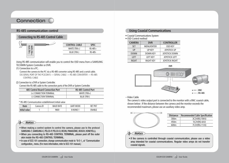
•Whenmakingacontrolsystemtocontrol thecamera,pleaseuse to theprotocolSAMSUNG-T,SAMSUNG-E,PELCO-P,PELCO-D,VICON,PANASONIC,BOSCH,HONEYELL).
•WhenyouconnectingtoRS-485CONTROLTERMINAL,pleasepeelofftheouterskininsidetheRS-485CONTROLTERMINAL.
•IncaseofSCC-101connection,changecommunicationmodeto『8-E-1』at 『Communicationconfiguration』menu.(Formoreinformation,refertoSCC-101manual.)
Notes
Using Coaxial Communications
DVD
• Coaxial Communications System• OSD Control method
DVR
Distance Recommended Cable Specification300m 3C2V(RG-59/U)450m 5C2V(RG-6/U)600m 7C2V(RG-11/U)
– Video Cable The camera's video output port is connected to the monitor with a BNC coaxial cable,
shown below : If the distance between the camera and the monitor exceeds the recommended maximum, please use an auxiliary video amp.
•If thecamera iscontrolled throughcoaxialcommunication,pleaseuseavideoamp intended forcoaxialcommunications.Regularvideoampsdonot transfercoaxial signals.
Notes
Using RS-485 communication will enable you to control the OSD menu from a SAMSUNG TECHWIN System Controller or DVR.(1) Connection to a PC. Connect the camera to the PC via a RS-485 converter using RS-485 and a serial cable. EX) SERIAL PORT OF THE PC(COM1) → SERIAL CABLE → RS-485 CONVERTER → RS-485
CONTROL CABLE
Connecting to RS-485 Control Cable
CONTROL CABLE SPEC WHITE (TRX+) RS-485+ BLUE (TRX-) RS-485-
* RS-485 Communication establishment initial value
485 Control Board Connection Port RS-485 Control Port(+) CONNECTION TERMINAL WHITE (TRX+)(-) CONNECTION TERMINAL BLUE (TRX-)
Item Camera ID BAUD RATE UART MODE RET PKT
Initial value 1 9600 8-NONE-1 ENABLE
(2) Connection to a DVR or System Controller. Connect the RS-485 cable to the connection ports of the DVR or System Controller.
WHITE (TRX+)
BLUE (TRX-)
CAMERA DVR CONTROLLERSET MENU/ENTER OSD KEYUP UP KEY JOYSTICK UP
DOWN DOWN KEY JOYSTICK DOWNLEFT LEFT KEY JOYSTICK LEFT
RIGHT RIGHT KEY JOYSTICK RIGHT
RS-485 communication control
Connection
• :BNC•---- :RS-485

COLOR CCD CAMERA User Guide16 COLOR CCD CAMERA User Guide17
Operating Your Camera
MAIN SETUPLENS DC
EXPOSUREBRIGHTNESS… SHUTTER… AGC………SENS-UP RETURN
WHITE BALATW… OUTDOOR… INDOOR…MANUAL… AWC→SET
SSDR OFF… ON
BACKLIGHT OFF… BLC… HLC
SSNR3 OFF… ON
DAY/NIGHT COLOR… B/W… AUTO
SPECIALIMAGE ADJ.… CAM TITLE… SYNC MOTION DET…PRIVACY DISCOMM ADJ LANGUAGE… RETURN
EXIT SAVE… NOT SAVE… RESET
1. Press the Function Setup switch.• Main setup menu is displayed on the monitor screen.
Use the Function Setup Switch whitin the camera.
2. Select a desired function using the Function Setup switch.• Place the cursor over a desired item.
3. Set up a selected item by using the Function Setup switch.4. To finish the setting, select ‘EXIT’ and press the Function Setup switch.
Change thestatususingtheFunctionSetupswitch.
•Anitemwiththe… iconalsohassubmenus.Toselectasubmenu,selectanitemwiththeiconandpresstheFunctionSetupswitch.
•Anitemwiththe---iconisunavailableduetofunctionsettings.
Notes
Using this function, you can control the screen brightness.1. When the SETUP menu screen is displayed, select‘LENS’by using the Function Setup
switch so that the arrow indicates‘LENS’.2. DC : You can adjust the minimum shutter and maximum value of ESC shutter mode.
LENS
3. THE Lens mode has sub menu items as listed below. - BRIGHTNESS : Adjusts the video brightness.
Menu Configuration
Menu Setup
MAIN SETUP
1.LENS DC 2.EXPOSURE
MAIN SETUP
1.LENS DC 2.EXPOSURE 3.WHITE BAL ATW 4.SSDR OFF 5.BACKLIGHT OFF 6.SSNR3 ON 7.DAY/NIGHT AUTO 8.SPECIAL 9.EXIT SAVE
SelectthefunctionusingtheFunctionSetupswitch.

COLOR CCD CAMERA User Guide18 COLOR CCD CAMERA User Guide19
MAIN SETUP
1.LENS DC 2.EXPOSURE 3.WHITE BAL ATW
•IfcolorrollingoccurswhenusingaDClens,setShuttertoFixed(---).
Notes
EXPOSURE
1. When the SETUP menu screen is displayed, select 'EXPOSURE' by using the Function Setup Switch.
2. Select a desired mode using the Function Setup switch.
•WhentheSHUTTERissettoMANUALorA.FLKmode,SENS-UPwillbedisabled.
Notes
AGC(AUTO GAIN CONTROL) : The higher the gain level, the brighter the screen - but the higher the noise.
- OFF : Deactivates the AGC function. - LOW : Allows automatic gain control from 5.3dB to 32dB. - HIGH : Allows automatic gain control from 5.3dB to 37dB. SENS-UP : When it is night or dark, the camera automatically detects the light level
and maintains a clear picture if this mode is activated. - OFF : Deactivates the SENS-UP function. - AUTO : Activates the SENS-UP function. RETURN : Select this to save the changes in the EXPOSURE menu and return to the
SETUP menu.
SHUTTER : You can select either auto or manual shutter. - --- : Shutter speed is fixed at 1/60sec(1/50sec) - ESC : Select this to control the shutter speed automatically. If ESC is selected, the
shutter speed is automatically controlled depending on the ambient illumination of the subject.
- MANUAL : You can control shutter speed manually. (NTSC MODEL : 1/60~1/120,000, PAL MODEL : 1/50~1/120,000)
- A.FLK : Select this when you see picture flicker, this can happen when the frequency of the local lighting clashes with the camera.
EXPOSURE SETUP
1.BRIGHTNESS 25
2.SHUTTER ---
3.AGC HIGH
4.SENS-UP OFF
5.RETURN Use the White Balance function to adjust the screen color.1. When the SETUP menu screen is displayed, select ‘White Bal’ by using the Function
Setup switch so that the arrow indicates ‘White Bal’.2. Select a desired mode using the Function Setup switch.
White Balance (White Bal)
•IfyoupresstheFunctionSetupswitchto‘AUTO’mode,youcanadjustbrightnessbyincreasingordecreasingtheshutterspeed.(x2~x512)
•Notethatthehigherthezoomlevel,thebrighterthescreen,butthemorelikelytherewillbeaghosting effect.
•It isnormal forNoise,SpotsandWhitishsymptomstoappear inSENS-UPmodewhentheD-ZOOMlevelisincreased.
Notes
- FOCUS ADJ : To adjust the DC lens focus correctly, you must activate the Focus Settings mode under each lens menu. Activate the Focus Settings mode, adjust the lens focus, and then deactivate the settings mode.
MAIN SETUP
1.LENS DC 2.EXPOSURE 3.WHITE BAL ATW 4.SSDR OFF
Operating Your Camera

COLOR CCD CAMERA User Guide20 COLOR CCD CAMERA User Guide21
※ Select one of the following 5 modes, as appropriate for your purpose. ATW : Select this when the color temperature is between 1,700˚K and 11,000˚K. OUTDOOR : Select this when the color temperature is between 1,700˚K and 11,000˚K.
(sodium light inclusion) INDOOR : Select this when the color temperature is between 4,500˚K and 8,500˚K. MANUAL : Select this to fine-tune White Balance manually. Set White Balance first
by using the ATW or AWC mode. After that switch to MANUAL mode, fine-tune the White Balance and then press the Function Setup switch.
AWC→SET : To find the optimal luminance level for the current environment, point the camera towards a sheet of white paper and press the Function Setup switch. If the environment changes, readjust it.
•WhiteBalancemaynotworkproperlyunderthefollowingconditions.InthiscaseselecttheAWCmode.
❶…………Whenthecolortemperatureoftheenvironmentsurroundingthesubjectisoutof the control range (e.g. clear sky or sunset).
2…Whentheambientilluminationofthesubjectisdim. 3……If the camera is directed towards a fluorescent light or is installed in a place
where illuminationchangesdramatically, theWhiteBalanceoperationmaybecomeunstable.
Notes
SSDR (Samsung Super Dynamic Range)
SSDR illuminates darker spots of an image while retaining the same light level for brighter spots to even out the overall brightness of images with high contrast between bright and dark spots.
SSDROFF
1. When the SETUP menu screen is displayed, select ‘SSDR’ by using the switch so that the arrow indicates ‘SSDR’.
2. Use the switch to change the SSDR level according to the contrast between bright and dark areas.
SSDRON
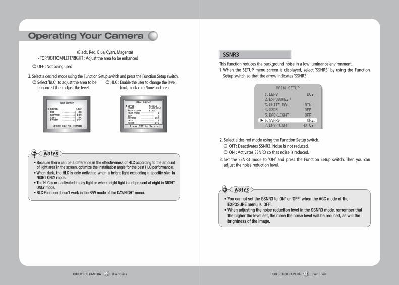
2. Select a desired mode using the Function Setup switch. BLC : Enables a user to directly select a desired area from a picture, and to view the
area more clearly.
BACKLIGHT
Unlike conventional cameras, the SCO-2080R is designed to deliver a distinctive subject and background at the same time, even when the subject is backlight, by using the features of the proprietary W-V DSP chip.1. When the SETUP menu screen is displayed, select ‘BACKLIGHT’ by using the Function
Setup switch so that the arrow indicates ‘BACKLIGHT’.
MAIN SETUP
1.LENS DC 2.EXPOSURE 3.WHITE BAL ATW 4.SSDR OFF 5.BACKLIGHT OFF
MAIN SETUP
1.LENS DC 2.EXPOSURE 3.WHITE BAL ATW 4.SSDR OFF 5.BACKLIGHT OFF 6.SSNR3 ON
Operating Your Camera
HLC (High Light Compensation) : If the scene contains extremely bright light areas such as; from car headlights, the
light can mask out much of the on-screen detail. - LEVEL : Adjust level of the HLC function. - LIMIT : Enable to change the operating condition. - MASK COLOR/TONE : Change the color / transparency of the masking area.
COLOR CCD CAMERA User Guide22 COLOR CCD CAMERA User Guide23
LOW
OFF : Not being used
3. Select a desired mode using the Function Setup switch and press the Function Setup switch. Select ‘BLC’ to adjust the area to be enhanced then adjust the level.
HLC : Enable the user to change the level, limit, mask color/tone and area.
•BecausetherecanbeadifferenceintheeffectivenessofHLCaccordingtotheamountoflightareainthescreen,optimizetheinstallationangleforthebestHLCperformance.
•Whendark,theHLCisonlyactivatedwhenabrightlightexceedingaspecificsizeinNIGHTONLYmode.
•TheHLCisnotactivatedindaylightorwhenbrightlightisnotpresentatnightinNIGHTONLYmode.
•BLCFunctiondoesn'tworkintheB/WmodeoftheDAY/NIGHTmenu.
Notes
This function reduces the background noise in a low luminance environment.1. When the SETUP menu screen is displayed, select ‘SSNR3’ by using the Function
Setup switch so that the arrow indicates ‘SSNR3’.
SSNR3
2. Select a desired mode using the Function Setup switch. OFF : Deactivates SSNR3. Noise is not reduced. ON : Activates SSNR3 so that noise is reduced.
3. Set the SSNR3 mode to ‘ON’ and press the Function Setup switch. Then you can adjust the noise reduction level.
MAIN SETUP
1.LENS DC 2.EXPOSURE 3.WHITE BAL ATW 4.SSDR OFF 5.BACKLIGHT OFF 6.SSNR3 ON 7.DAY/NIGHT AUTO
Operating Your Camera
•YoucannotsettheSSNR3to‘ON’or‘OFF’whentheAGCmodeoftheEXPOSUREmenuis‘OFF’.
•WhenadjustingthenoisereductionlevelintheSSNR3mode,rememberthatthehigherthelevelset,themorethenoiselevelwillbereduced,aswillthebrightnessoftheimage.
Notes
(Black, Red, Blue, Cyan, Magenta) - TOP/BOTTOM/LEFT/RIGHT : Adjust the area to be enhanced

COLOR CCD CAMERA User Guide24 COLOR CCD CAMERA User Guide25
MAIN SETUP
1.LENS DC 2.EXPOSURE 3.WHITE BAL ATW 4.SSDR OFF 5.BACKLIGHT OFF 6.SSNR3 ON 7.DAY/NIGHT AUTO 8.SPECIAL
You can display pictures in color or black and white.1. When the SETUP menu screen is displayed, select ‘DAY/NIGHT’ by using the Function
Setup switch so that the arrow indicates ‘DAY/NIGHT’ .
DAY/NIGHT
2. Select a desired mode using the Function Setup Switch according to the picture display you want.
B/W MODE SETUP
1.BURST MODE ON 2.IR MODE ON 3.IR LEVEL HIGH 4.RETURN
COLOR : The picture is always displayed in color.
B/W : The picture is always displayed in black and white. - BURST MODE : You can turn on or off the burst signal on B/W
mode. - IR MODE : When IR LED is turned on in B/W, the objects
can be clearly identified due to the function that decreases screen saturation of objects within a short distance.
· TOP/BOTTOM/LEFT/RIGHT : Adjust the range according to the location of objects. - IR LEVEL : Select LOW when objects appears within a short distance or select HIGH
when objects appears within a long distance on the screen.
AUTO : The mode is switched to ’Color‘ in a normal environment, but switches to ’B/W‘ mode when ambient illumination is low. To set up the switching time for AUTO mode, press the Function Setup switch. You can turn on or off the burst signal on B/W mode.
* The day/night switching point of the camera can be adjusted.
Color → B/W B/W → ColorFast 2.5 lux 5 luxSlow 1 lux 10 lux
- BURST MODE : You can turn on or off the burst signal on B/W mode.
- DURATION : You can select brightness of illumination about changing the day/night mode.
- DWELL TIME : You can select the duration time about changing the day/night mode. …→3s, 5s, 7s, 10s, 15s, 20s, 30s, 40, 60s
AUTO SETUP…1.BURST MODE ON 2.COLOR→B/W DURATION FAST DWELL TIME 3SEC 3.B/W→COLOR DURATION FAST DWELLTIME 10SEC 4.RETURN
•WhenAGCintheEXPOSUREmenuis'OFF','---'modeoperatesaslikeselecting'COLOR'modeand'AUTO'modecannotbeselected.
Notes
Operating Your Camera
COLOR CCD CAMERA User Guide26 COLOR CCD CAMERA User Guide27
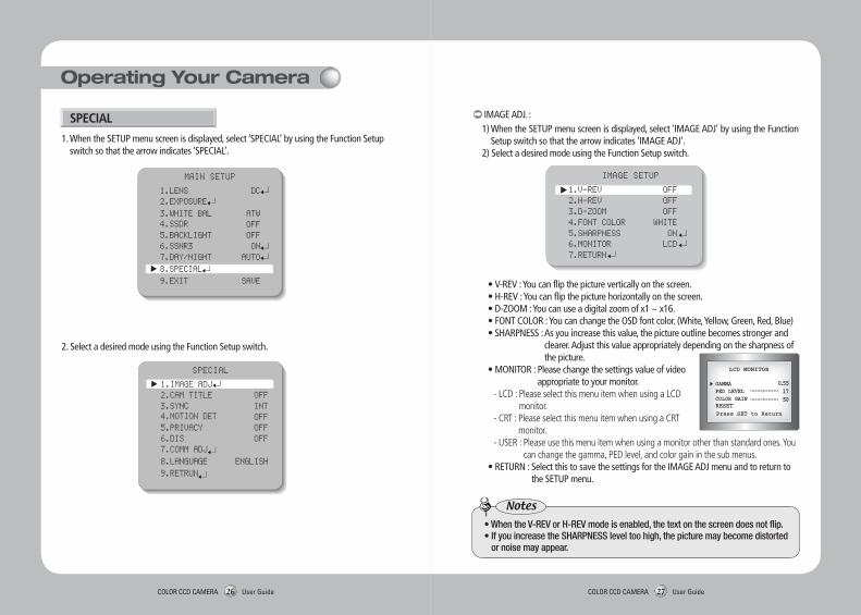
2. Select a desired mode using the Function Setup switch.
IMAGE SETUP
1.V-REV OFF 2.H-REV OFF 3.D-ZOOM OFF 4.FONT COLOR WHITE 5.SHARPNESS ON 6.MONITOR LCD 7.RETURN
IMAGE ADJ. : 1) When the SETUP menu screen is displayed, select ‘IMAGE ADJ’ by using the Function
Setup switch so that the arrow indicates ’IMAGE ADJ‘. 2) Select a desired mode using the Function Setup switch.
•V-REV : You can flip the picture vertically on the screen. •H-REV : You can flip the picture horizontally on the screen. • D-ZOOM : You can use a digital zoom of x1 ~ x16. • FONT COLOR : You can change the OSD font color. (White, Yellow, Green, Red, Blue) •SHARPNESS : As you increase this value, the picture outline becomes stronger and
clearer. Adjust this value appropriately depending on the sharpness of the picture.
•MONITOR : Please change the settings value of video appropriate to your monitor.
- LCD : Please select this menu item when using a LCD monitor.
- CRT : Please select this menu item when using a CRT monitor.
- USER : Please use this menu item when using a monitor other than standard ones. You can change the gamma, PED level, and color gain in the sub menus.
•RETURN : Select this to save the settings for the IMAGE ADJ menu and to return to the SETUP menu.
1. When the SETUP menu screen is displayed, select ‘SPECIAL’ by using the Function Setup switch so that the arrow indicates ‘SPECIAL’.
SPECIAL
•WhentheV-REVorH-REVmodeisenabled,thetextonthescreendoesnotflip.•IfyouincreasetheSHARPNESSleveltoohigh,thepicturemaybecomedistorted
or noise may appear.
Notes
MAIN SETUP
1.LENS DC 2.EXPOSURE 3.WHITE BAL ATW 4.SSDR OFF 5.BACKLIGHT OFF 6.SSNR3 ON 7.DAY/NIGHT AUTO 8.SPECIAL 9.EXIT SAVE
SPECIAL
1.IMAGE ADJ 2.CAM TITLE OFF 3.SYNC INT 4.MOTION DET OFF 5.PRIVACY OFF 6.DIS OFF 7.COMM ADJ 8.LANGUAGE ENGLISH 9.RETRUN
Operating Your Camera

COLOR CCD CAMERA User Guide28 COLOR CCD CAMERA User Guide29
FRONT DOOR
•WhentheCAMTITLEmenuis‘OFF’,notitlewillbedisplayedonthemonitorscreeneven if you enter one.
•OnlyEnglishisavailableinthismode.•IfyoumovethecursortoCLRandpresstheFunctionSetupswitch,allthelettersaredeleted.Toeditaletter,changethecursortothebottomleftarrowandpresstheFunctionSetupswitch.Movethecursoroverthelettertobeedited,movethecursortothelettertobeinsertedandthenpresstheFunctionSetupswitch.
Notes
SYNC : In areas where the supply is at 60Hz(NTSC), 50Hz(PAL), you can synchronize the output phase of multiple cameras using the power synchronization function (Line-Lock) without using a synchronization signal generator.
- INT : Internal Synchronization Type - L/L : Power Synchronization Type, Line-lock • Press the Function Setup switch. • You can select a desired phase from 0 to 359 when select 'phase'.
•WhenusingACpowerat60Hz(NTSC),50Hz(PAL),frequency,youcanusetheL/Ltypesynchronization.
•WhenthepowerisDC12V,theSYNCmenuisfixedtothe‘INT’mode.
Notes
MOTION DET : This product has a feature that allows you to observe
movement of objects in 8 different areas on the screen, and the words 'MOTION DETECTED' appear on the screen when movement is detected. Activity can be monitor more efficiently.
1) When the SPECIAL menu screen is displayed, press the Function Setup switch so that the arrow indicates‘MOTION DET’.
2) Set up the mode using the Function Setup switch.
- SENSITIVITY : You can select up to 8 MD areas. When SENSITIVITY number is high, motion detection sensitivity is increased to recognize even small movement.
- AREA MODE : Determines whether to use the MD area selected in SENSITIVITY. - SEL POS : Determines which of the 4 vertices of each MD area is to be used. - XPOS : Determines the coordinate of the horizontal axis for SEL POS. - YPOS : Determines the coordinate of the vertical axis for SEL POS. - FILL→SET : Fills in a selected MD area. The color of the area can be selected from
brown, orange, blue, cyan, green, yellow, magenta and red. - RETURN : Select this to save the MOTION DET menu settings and return to the SPECIAL menu.
3) Press the Function Setup switch. 4) Use the Function Setup switch to move to
a desired letter and select the letter by pressing the Function Setup switch. Repeat this to enter multiple letters. You can enter up to 15 letters.
5) Enter a title, move the cursor to ‘POS’ and press the Function Setup switch. The entered title appears on the screen. Select the position to display the title on the screen by using the Function Setup switch and press the Function Setup switch. When the position is determined, select ‘END’ and press the Function Setup switch to return to the SPECIAL menu.
CAM TITLE : If you enter a title, the title will appear on the monitor. 1) If the SPECIAL menu screen is displayed, use the Function Setup switch so that the
arrow indicates ‘CAM TITLE’. 2) Set it to ‘ON’ by using the Function Setup switch.
CAMERA TITLE SETUP
A B C D E F G H I J K L MN O P Q R S T U V W X Y Za b c d e f g h i j k l mn o p q r s t u v w x y z- . 0 1 2 3 4 5 6 7 8 9
← → C L R P O S E N D
Operating Your Camera

COLOR CCD CAMERA User Guide30 COLOR CCD CAMERA User Guide31
•AstheDISfunctionusesthedigitalzoomthecamera'sresolutionwilldecrease.•DISdoesn’toperatewhenbackgroundilluminationistoolow.•DISdoesn’toperatewhenobjectpatternismonotonicaslikeskyorwhitewall.
Notes
DIS (Digital Image Stabilizer) : This function mitigates any picture movement due to external factors such as wind.
1) … When the SPECIAL menu screen is displayed, press the Function Setup switch so that the arrow indicates ‘PRIVACY’.
… … … 2) … Set up the mode using the Function Setup switch. - AREA : You can select up to 12 PRIVACY areas. - MODE : Determines whether to use the area selected in the AREA. - MASK COLOR : Determine area color. You can select Green, Red, Blue, Black, White, Gray. - MASK TONE : Adjust the brightness of MASK COLOR. - TOP/BOTTOM/LEFT/RIGHT : Adjust the size and position of the selected area. - RETURN : Select this to save the PRIVACY menu settings and return to the SPECIAL menu.
COMM ADJ (Communication Adjustment) : This function sets up the camera communication status when controlling the camera through an external control device.
… 1) … When the SPECIAL menu screen is displayed, press the Function Setup switch so that the arrow indicates ‘COMM ADJ’.
… … 2) … Set up the mode using the Function Setup witch. - CAM ID : Determines the camera's identification
number (between 0 and 255). - BAUD RATE : You can select 2400/4800/9600/19200
/38400/57600 bps. - UART MODE : You can select NONE, EVEN or ODD
for the parity bits. - RET PKT : Determines whether to send a command
back to the controller device when a communication control command is sent to the camera.
- DISP ID : Display camera title on top left corner of the screen. - PROTOCOL : You can select one of various protocols. SAMSUNG-T, SAMSUNG-E,
PELCO-P, PELCO-D, VICON, PANASONIC, BOSCH, HONEYWELL.
* Initial value of communication adjustment Item Camera ID BAUD RATE UART MODE PET PKT
Initial value 1 9600 8-NONE-1 ENABLE
Select a desired EXIT mode using the Function Setup Switch.- SAVE : Save the current settings and exit the MAIN SETUP menu.- NOT SAVE : Do not save the current settings and exit the MAIN SETUP menu.- RESET : Resets the camera settings to the factory defaults. Language,
Communication and Monitor Settings are not initialized.
LANGUAGE : You can select the menu language according to your requirements.
RETURN : Select this to save the SPECIAL menu settings and return to the MAIN SETUP menu.
EXIT
PRIVACY : Mask an area you want to hide on the screen.
PRIVACY AREA SETUP
1.AREA AREA1 2.MODE OFF 3.MASK COLOR GREEN 4.MASK TONE 1 5.TOP 39 6.BOTTOM 79 7.LEFT 13 8.RIGHT 52 9.RETURN
Operating Your Camera

COLOR CCD CAMERA User Guide32 COLOR CCD CAMERA User Guide33
Troubleshooting
If there are problems in operation, please refer to the items below. If theproblem persists, please contact the agent you purchased this product from.
• Nothing appears on the screen. Check that the power cord and line connection between the camera and monitor are
fixed properly. Check that you have properly connected UTP cable or BNC cable to the camera.
• The image on the screen is dim. Is lens stained with dirt? Clean your lens with soft, clean cloth. Set the monitor to proper condition. If the camera is exposed to too strong light, change the camera position.
• The image on the screen is dark. Adjust the contrast feature of the monitor. If you have an intermediate device, set the 75Ω / Hi-z properly.
• The camera is not working properly, and the surface of the camera is hot. Check that you have properly connected the camera to an appropriate power source.
• The SENS-UP function does not work. Check that AGC of EXPOSURE SETUP menu is ‘OFF’. Check that SHUTTER of EXPOSURE SETUP menu is ‘A.FLK’ or ‘MANUAL’.
• The Motion Detection function does not work. Check that MOTION DET of SPECIAL SETUP menu is ‘OFF’.
• Color is not correct. Check the setting of WHITE BAL SETUP menu.
• The screen flickers continually. Check that direction of camera turns toward the Sun.
• When coaxial communication is not available: Make sure that the camera and monitor are installed within the recommended distance. Use the video amplifier equivalent to coaxitron if the recommended installation distance is
exceeded.
• IR-LED isn’t lighted. Isn’t DAYNIGHT function setting up the color mode? Please change the AUTO or B/W mode.
• The camera is not waterproof. Please check the Front Cover and Main Body by the following Guide Label.
Specifications
※ The specification for this product may change without prior notice for product improvement.
SCO-2080RN SCO-2080RPELECTRICALInput Voltage DC 12V ± 10% / AC 24V ± 10%Power Consumption Max 6.8W / 6.5W (IR-LED ON)VIDEOImaging Device 1/3 inch, Diagonal 6mm Super HAD CCDTotal Pixels 811(H) x 508(V) 795(H) x 596(V)Effective Pixels 768(H) x 494(V) 752(H) x 582(V)Scanning System 2:1 InterlaceSynchronization Internal /Line-LockFrequency H : 15.734KHz V:59.94Hz H: 15.625KHz V: 50.00HzHorizontal Resolution COLOR : 600TV line, B/W : 700TV line
Min. IlluminationLED ON : 0LuxLED OFF : 0.15Lux (Color, F1.2), 0.0003Lux (Color,SENS-UP x512)
Visibility distanse(IR LED) 50m (32EA)S/N (Y Signal) 52dB (Weight On, AGC Off)Video Output CVBS : 1.0Vp-p, 75Ω compositeLENSZoom Ratio 3.6x (Manual)Focus Length 2.8 ~ 10.0mm (F1.2)Angular Field of View H : 94.4°(Wide) ~ 28°(Tele) / V : 69.2°(Wide) ~ 21°(Tele)OPERATIONALElectronic Shutter Speed 1/60 ~ 1/120k sec 1/50 ~ 1/120k secOn Screen Display NTSC : 7 Languages, PAL : 15 LanguagesSSDR On / Off (Level adjustable)Backlight Compensation BLC / HLC / OFFDay & Night COLOR / B/W / AUTO (ICR)Gain Control Low / High / OffWhite Balance ATW / Outdoor / Indoor / Manual / AWC (1,700°K ~ 11,000°K)SENS-UP (frame Integration) Auto / Off (Selectable x2 ~ x512)Motion Detection On / Off (8 Programmable zones)Privacy Masking On / Off (12 Programmable zones)3D Noise Filter (SSNRIII) On / Off (Level adjustable)Digital Zoom On / Off (x1 ~ x16)Digital Image Stabilization(DIS) On / OffCamera Title On / Off (Displayed 15 Characters)Sharpness On / Off (Level adjustable)Flip / Mirror On / OffCommunication Coaxial, RS-485
ProtocolCoaxial(Pelco), RS-485(SAMSUNG-T, SAMSUNG-E, PELCO-P, PELCO-D, VICON, PANASONIC, BOSCH, HONEYWELL)
ENVIRONMENTALOperating Temperature / Humidity -10°C ~ +55°C / Less than 90% RHMECHANICALWater Resistance IP66Dimension Ø77mm(W) x 216mm(H) (BRACKET ANGLE 90°), 284mm (BRACKET ANGLE 180°)Weight 1Kg

COLOR CCD CAMERA User Guide34 COLOR CCD CAMERA User Guide35
DECLARATION OF CONFORMITY
ApplicationofCouncilDirective(s) 2004/108/EC
Manufacturer'sName SAMSUNGTECHWINCO.,LTD
Manufacturer'sAddress SAMSUNGTECHWINCO.,LTD
42,SUNGJU-DONGCHANGWON-CITY,
KYUNGNAM,KOREA,641-716
EuropeanRepresentativeName
EuropeanRepresentativeAddress
EquipmentType/Environment CCTVCamera
ModelName SCO-2080RP
BeginningSerialNO. C5AM6V3Z200001X
YearofManufacture 2010.02.01
Conformanceto EN55022:2006
EN50130-4:2003
We,theundersigned,herebydeclarethattheequipmentspecifiedaboveconforms
totheaboveDirective(s).
Manufacturer SAMSUNGTECHWINCO.,LTD LegalRepresentativeinEurope
Signature Signature
FullName BONJENGGU FullName
Position QUALITYCONTROLMANAGER Position
Place CHANGWON,KOREA Place
Date 2010.02.01 Date
Dimension
86mm
274.7mm
244.7mm
Ø77
Ø79.8
118.5m
m

P/No. : Z6806-1157-01B VAN 10. 04
www.samsungtechwin.comwww.samsungsecurity.com
• SAMSUNG TECHWIN CO., LTD.Samsungtechwin R&D Center, 701, Sampyeong-dong, Bundang-gu, Seongnam-si, Gyeonggi-do, Korea, 463-400TEL : +82-70-7147-8740~60 FAX : +82-31-8018-3745
• SAMSUNG TECHWIN EUROPE LTD. Samsung House, 1000 Hillswood Drive, Hillswood BusinessPark Chertsey, Surrey, UNITED KINGDOM KT16 OPSTEL : +44-1932-45-5300 FAX : +44-1932-45-5325
• SAMSUNG TECHWIN AMERICA Inc.1480 Charles Willard St, Carson, CA 90746, UNITED STATESTol Free : +1-877-213-1222 FAX : +1-310-632-2195www.samsungcctvusa.com
SALES NETWORK


