High-resolution monochromaticx-ray imaging system based on spherically bent crystals
Yefim Aglitskiy, Thomas Lehecka, Stephen Obenschain, Stephen Bodner, Carl Pawley,Kent Gerber, John Sethian, Charles M. Brown, John Seely, Uri Feldman, and Glenn Holland
X-ray diagnostics are powerful tools for the study ofdense laser-produced plasmas. The surface of theseplasmas is hot enough to produce significant quanti-ties of x radiation for emission spectroscopy. How-ever, it is also necessary to diagnose relatively coldand dense portions of targets to determine their massnonuniformity. These cold dense plasmas havebeen diagnosed by absorption of x rays from externalsources,1–14 including x-ray lasers.15–17 These twospectroscopic diagnostics, emission and absorption,have similar requirements of high spectral, spatial,and temporal resolution.
The high-power Nike KrF laser at the Naval Re-search Laboratory ~NRL! is being used to accelerateflat plastic targets and to study methods of mini-mizing the hydrodynamic instabilities that arisefrom this acceleration. The laser focal spot size is;0.75 mm FWHM with a 0.4-mm flattop in the
Y. Aglitskiy and T. Lehecka are with the Science ApplicationsInternational Corporation, McLean, Virginia 22102. S. Oben-schain, S. Bodner, C. Pawley, K. Gerber, and J. Sethian are withthe Plasma Physics Division, Naval Research Laboratory, Wash-ington, D.C. 20375. C. M. Brown, J. Seely, and U. Feldman arewith the Space Science Division, Naval Research Laboratory,Washington, D.C. 20375. G. Holland is with SFA Inc., 1401 Mc-Cormic Drive, Landover, Maryland 20785.
Received 23 December 1997; revised manuscript received 11March 1998.
center. The large spot size is necessary to diag-nose long-wavelength perturbations in the targetand to minimize the edge effects from the acceler-ation process. These experiments therefore re-quire a diagnostic field of view of ;1 mm, so that theentire acceleration region as well as the remainingintact part of the target foil is within the picture.Because of the smoothness of the Nike focal inten-sity distribution, we expect the mass modulationsdue to laser imprint to be small. This means thathigh-contrast imaging is required. Theoreticaltwo-dimensional ~2-D! simulations of the develop-ment of Rayleigh–Taylor ~R–T! instabilities ~see, forexample, Fig. 8! show that seeded mass perturba-tions with relatively long spatial periods developmuch narrower features at the end of the laserpulse. Thus the ability to resolve the objects witha size of 5 mm is highly desired.
We obtained time resolution with a framing cam-ra as a detector. The common drawback of theseevices is a relatively low spatial resolution of0–50 mm that implies that high image magnifica-ion ~at least 203! is required. This high magnifi-ation in turn requires high throughput of theystem. Our experiments with thick plastic targetsapproximately 40–60 mm! also require the diagnos-ics to have high efficiency and the probing radiationo have high energy. This requirement differs fromhe previous experiments with relatively thin targetssee, for example, Ref. 18!.
For any backlighting scheme there are two othereneral requirements: that the backlighter source
1 August 1998 y Vol. 37, No. 22 y APPLIED OPTICS 5253
awcfss
woarifwm
mwtptw
wtitbspcf
olpsTaobtmodoqi
tftpsa
piRRaRll
5
have a small size and that there be filtration of im-aging radiation from the self-emission of the object.If the dimension of the source of backlighting radia-tion is small, the amount of power required to createit can be much smaller than the power driving theobject. If spectral filtration is available, the surfacebrightness of the backlighter must be larger than theobject brightness only in the bandwidth of the spec-tral line being used to image the object.
Among well-known imaging systems such asKirkpatrick–Baez microscopes,19–21 pinhole cameras,Fresnel zone plates, and Bragg–Fresnel structures,22
only spherically bent crystals meet all our require-ments simultaneously.9,23–31 ~A more detailed com-parison of the imaging methods is in Section 5.!
Described below is a high spectral and spatial res-olution instrument based on spherically curved crys-tals. Its applications include the following:
1. One-dimensional ~1-D! imaging with spectralresolution.26
2. 2-D self-imaging in the light of an individualspectral line or in the light of an intense continuumwith a wavelength band as narrow as 0.01 Å.27,28
Initial results with this spherical imaging tech-nique were presented in an earlier paper.28 Here wediscuss results from spherical crystals of much im-proved quality that allowed imaging over larger fieldsof view with higher spatial resolution. We used thisimproved instrument for studying laser imprintingand Rayleigh–Taylor growth of instabilities in plastictargets accelerated by the Nike KrF laser.
2. General Description of the Optical System
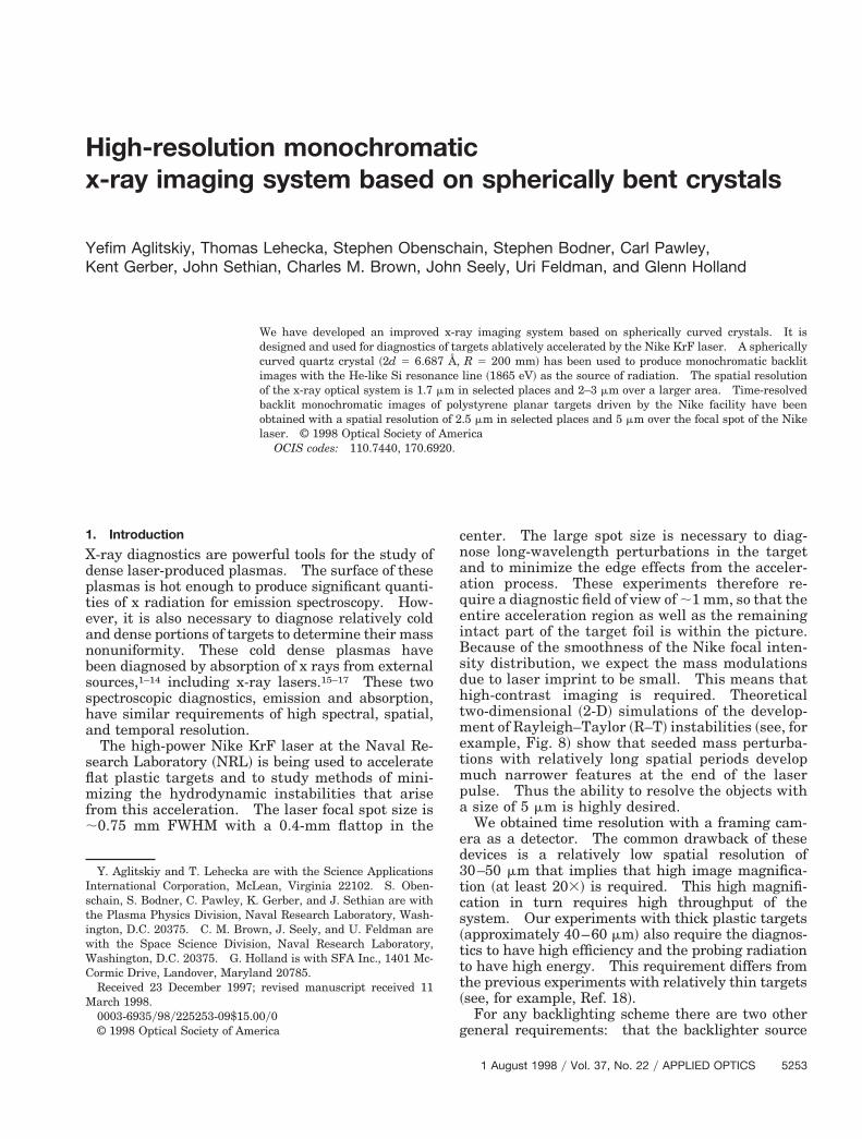
The optical scheme of monochromatic x-raybacklighting9,23–31 is presented in Fig. 1. The im-aging of two principal points of the main target ~top
nd bottom! is shown. For the scheme descriptione use here the familiar Rowland circle, which is a
urve where all x rays with a given wavelength locus to a point. There is no restriction on theource location provided the radiation wavelength latisfies the Bragg equation:
2d sin u 5 ml,
Fig. 1. Principal optical scheme of backlighting with the use ofspherically bent crystals: ~a!, small area of the crystal that isactually involved in the imaging of a single point of the target~shown for two edge points!.
254 APPLIED OPTICS y Vol. 37, No. 22 y 1 August 1998
here d is the crystal interplanar distance, m is therder of reflection, and u is the Bragg angle ~grazingngle!. The use of the Rowland circle is strictly cor-ect only in the meridional plane ~or the plane ofncidence that includes the incident ray and the sur-ace normal!. Actually a Rowland sphere applieshen one considers the Bragg reflection in three di-ensions.The x-ray backlighter source is located between theain target and the Rowland circle of radius Ry2,here R is the radius curvature of the crystal. The
arget ~or a test mesh! to be imaged is placed in theath of the rays between the backlighter source andhe spherically bent crystal at a distance f , a , 2fith
f 5 ~Ry2!sin u 5 cy2,
here f is the focal length of the spherical crystal inhe meridional plane, a is the distance between thenvestigated object and the crystal, and c is the dis-ance between the crystal and the projection of theacklighter source on the Rowland circle. Thehadow image of the object will appear at the imageosition ~detector or film! at a distance b from therystal, where b is determined by the familiar mirrorormula:
1ya 1 1yb 5 1yf.
Spherical Bragg optics is essentially an off-axis usef a spherical mirror, and image resolution is alwaysimited by astigmatism. Thus, even if the object isositioned relatively close to the normal, there aretill different horizontal and vertical focal distances.he best compromise focus is somewhere between,nd the image quality depends on the depth of focusf the optical system. In the case of a small sourceacklighting a specific point of the object, the area ofhe crystal involved in the imaging of this point isuch smaller than the crystal itself ~see Fig. 1!. In
ur case this area is ;0.8 mm in diameter. With aistance to the image of ;2000 mm, good focusing isbtained. A corollary to this observation is that theuality of an image point is affected only by the qual-ty of the crystal bending in this small region.
The choice of spectral line ~or a wavelength band ofhe continuum! depends on the Bragg angle, which,or the practical reason given above, must be kept inhe range of 80–88 deg. With a given energy of therobing radiation, the choices of crystals, backlighterource materials, and suitable plasma parametersre therefore limited.The backlighter source is usually located near the
erpendicular to the crystal center but not necessar-ly on the Rowland circle. If the source lies on theowland circle, the focal distances in the plane of theowland circle and in the plane perpendicular to itre nearly the same and are equal to the radius of theowland circle Ry2. If the source is inside the Row-
and circle, a magnified image of the backlighter isocated outside the Rowland circle.
Owing to the focusing of the backlighter radiation
Fco
mfc
3~hfbr
liftit
m
ps
a
~
xabii
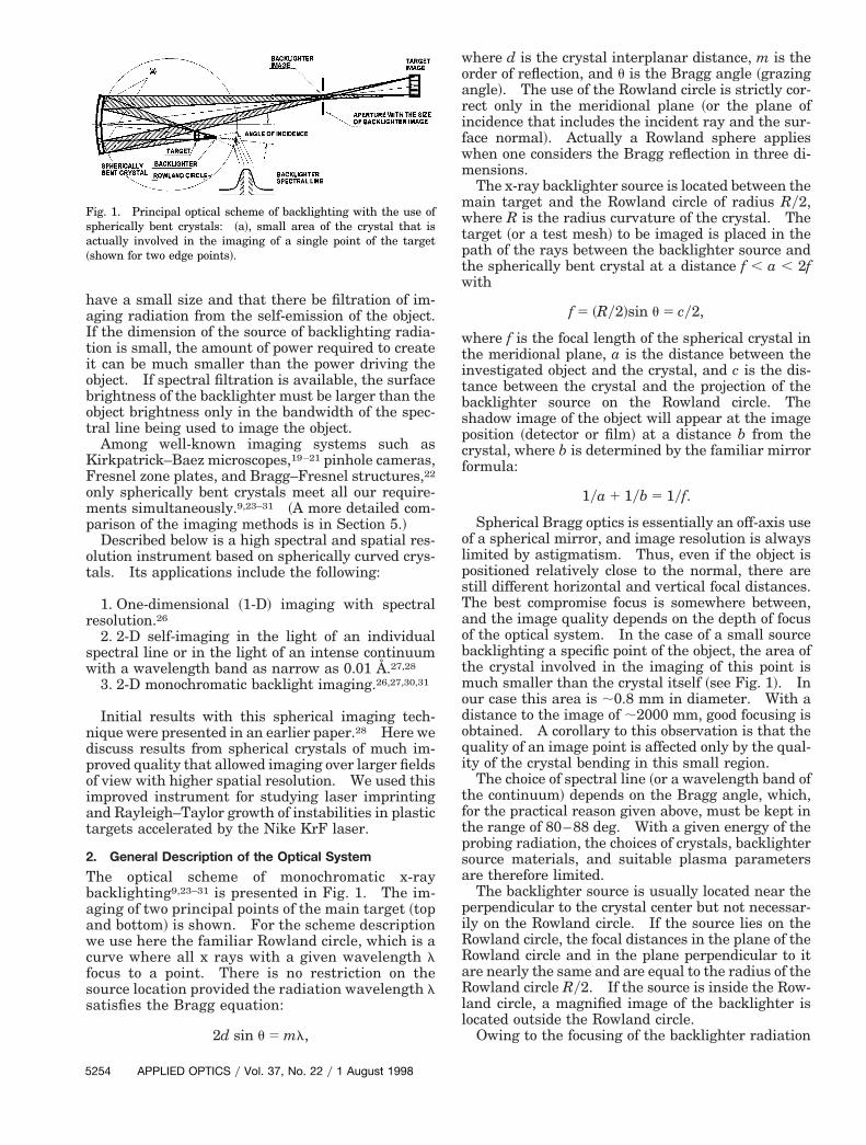
source between the crystal and the object image ~seeig. 2!, it is possible to protect the film or framingamera from a significant portion of the self-radiationf the object being imaged.The backlighter source size Dx and position deter-ine the spectral range of the radiation involved in
orming the image. If the source lies on the Rowlandircle, this range can be estimated with
Dl 5 Dx~lyR!cot u.
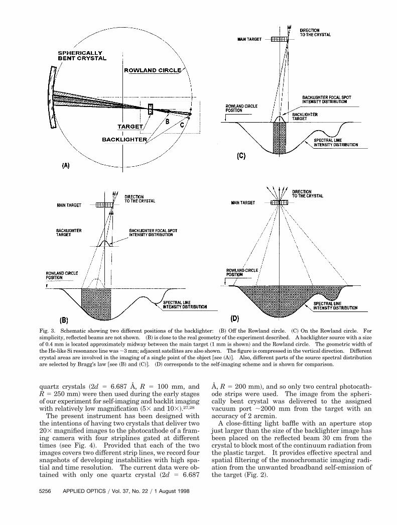
Since u is close to 90 deg, even if the real size of thesource Dx is 1–2 mm, the wavelength range Dl of thediffracted radiation of the crystals used so far ~crystalradii, R 5 100–500 mm! is not larger than ~0.3–2! 31023 l. This range is comparable with or smallerthan the width of a laser-produced soft-x-ray spectralline. For the present experimental setup on Nike,R 5 200 mm, the Bragg angle is 83.9°, the typicalbacklighter diameter is 400 mm, and the predicted Dlis ;0.0014 Å, less than the expected linewidth of;0.01 Å as revealed in Ref. 26 @see Fig. 3~C!#. If thebacklighter source is located between the object andthe Rowland circle, the wavelength range is wider@see Fig. 3~B!#. But owing to the high dispersionencountered at Bragg angles near 90°, it still is of theorder of a spectral linewidth. As seen from Fig. 3, anoff-circle position of the backlighter has the advan-tage of using more of the available radiation from aspectral line. It comes at the price of a larger crystalarea being involved in imaging a single point @Fig.~A!# and therefore of potentially lower resolutionbecause we increase the spherical aberration andave greater optical distortion if the crystal is imper-
ectly bent!. Thus there is an optimal position of theacklighter as a compromise between efficiency andesolution.
The case of self-imaging of the target using theight of a single spectral line is shown for comparisonn Fig. 3~D!. The cone of the x rays involved in theormation of an image of a single point is much widerhan in backlighting; thus astigmatism affects themage quality more severely. The requirements ofhe bending quality must also be higher.
The field of view l is determined by the arrange-ent of the source and the size of the crystal. In
Fig. 2. Spectral and spatial filtration of the backlighter imagingradiation from the self-emission of target plasma. An image ofthe target central point is shown.
articular, it depends on the magnification k of theetup according to
l 5 L@l–fyd~1 1 lyk!#,
where L is the aperture of the crystal, f is the focallength, and d is the distance between a backlighterand a crystal. When k is large and the backlighter ison the Rowland circle ~d close to 2f !, the field of viewis close to Ly2. If the backlighter source is locatedcloser to the target to be imaged, the field of view issmaller. The dimensions of the crystal used in theseexperiments are 5 mm 3 10 mm. The field of view isa few millimeters ~in each direction!.
3. Scheme of the Experiment
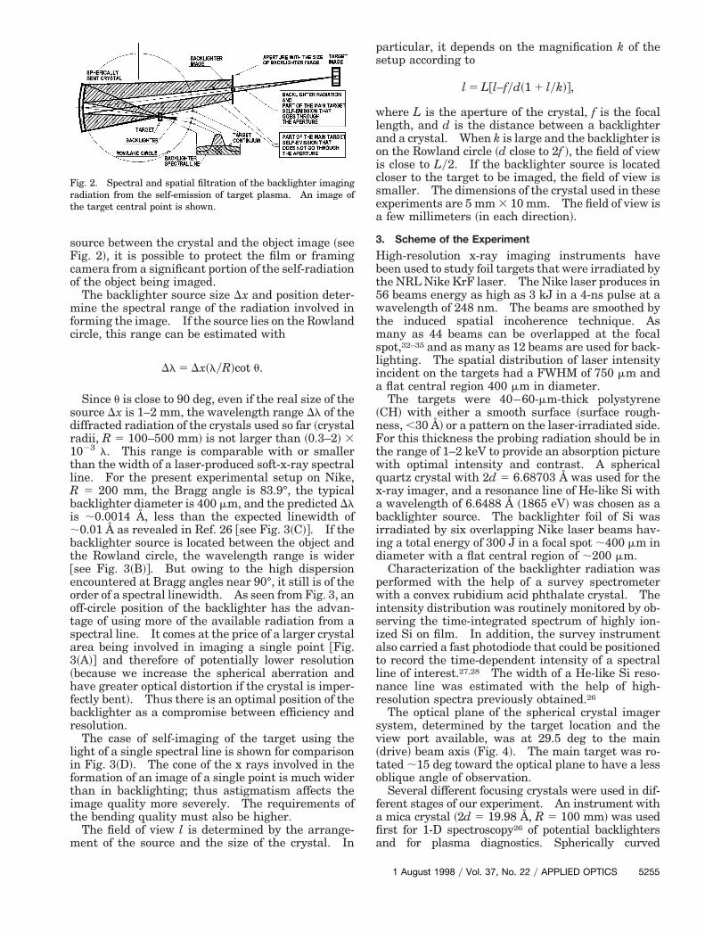
High-resolution x-ray imaging instruments havebeen used to study foil targets that were irradiated bythe NRL Nike KrF laser. The Nike laser produces in56 beams energy as high as 3 kJ in a 4-ns pulse at awavelength of 248 nm. The beams are smoothed bythe induced spatial incoherence technique. Asmany as 44 beams can be overlapped at the focalspot,32–35 and as many as 12 beams are used for back-lighting. The spatial distribution of laser intensityincident on the targets had a FWHM of 750 mm and
flat central region 400 mm in diameter.The targets were 40–60-mm-thick polystyrene
CH! with either a smooth surface ~surface rough-ness, ,30 Å! or a pattern on the laser-irradiated side.For this thickness the probing radiation should be inthe range of 1–2 keV to provide an absorption picturewith optimal intensity and contrast. A sphericalquartz crystal with 2d 5 6.68703 Å was used for the-ray imager, and a resonance line of He-like Si withwavelength of 6.6488 Å ~1865 eV! was chosen as a
acklighter source. The backlighter foil of Si wasrradiated by six overlapping Nike laser beams hav-ng a total energy of 300 J in a focal spot ;400 mm in
diameter with a flat central region of ;200 mm.Characterization of the backlighter radiation was
performed with the help of a survey spectrometerwith a convex rubidium acid phthalate crystal. Theintensity distribution was routinely monitored by ob-serving the time-integrated spectrum of highly ion-ized Si on film. In addition, the survey instrumentalso carried a fast photodiode that could be positionedto record the time-dependent intensity of a spectralline of interest.27,28 The width of a He-like Si reso-nance line was estimated with the help of high-resolution spectra previously obtained.26
The optical plane of the spherical crystal imagersystem, determined by the target location and theview port available, was at 29.5 deg to the main~drive! beam axis ~Fig. 4!. The main target was ro-tated ;15 deg toward the optical plane to have a lessoblique angle of observation.
Several different focusing crystals were used in dif-ferent stages of our experiment. An instrument witha mica crystal ~2d 5 19.98 Å, R 5 100 mm! was usedfirst for 1-D spectroscopy26 of potential backlightersand for plasma diagnostics. Spherically curved
1 August 1998 y Vol. 37, No. 22 y APPLIED OPTICS 5255
R
istt
Åocv
5
quartz crystals ~2d 5 6.687 Å, R 5 100 mm, and5 250 mm! were then used during the early stages
of our experiment for self-imaging and backlit imagingwith relatively low magnification ~53 and 103!.27,28
The present instrument has been designed withthe intentions of having two crystals that deliver two203 magnified images to the photocathode of a fram-ing camera with four striplines gated at differenttimes ~see Fig. 4!. Provided that each of the twomages covers two different strip lines, we record fournapshots of developing instabilities with high spa-ial and time resolution. The current data were ob-ained with only one quartz crystal ~2d 5 6.687
Fig. 3. Schematic showing two different positions of the backligsimplicity, reflected beams are not shown. ~B! is close to the real gof 0.4 mm is located approximately midway between the main tarthe He-like Si resonance line was ;3 mm; adjacent satellites are alscrystal areas are involved in the imaging of a single point of the obare selected by Bragg’s law @see ~B! and ~C!#. ~D! corresponds to
256 APPLIED OPTICS y Vol. 37, No. 22 y 1 August 1998
, R 5 200 mm!, and so only two central photocath-de strips were used. The image from the spheri-ally bent crystal was delivered to the assignedacuum port ;2000 mm from the target with an
accuracy of 2 arcmin.A close-fitting light baffle with an aperture stop
just larger than the size of the backlighter image hasbeen placed on the reflected beam 30 cm from thecrystal to block most of the continuum radiation fromthe plastic target. It provides effective spectral andspatial filtering of the monochromatic imaging radi-ation from the unwanted broadband self-emission ofthe target ~Fig. 2!.
: ~B! Off the Rowland circle. ~C! On the Rowland circle. Fortry of the experiment described. A backlighter source with a size
1 mm is shown! and the Rowland circle. The geometric width ofwn. The figure is compressed in the vertical direction. Different@see ~A!#. Also, different parts of the source spectral distributionelf-imaging scheme and is shown for comparison.
htereomeget ~o shojectthe s
w
1Hclt~stbmTcs2~masi~bTb
A 0.5-mil high-purity Be cover was used to protectthe crystal from debris. Owing to the steep angle ofincidence, it covers the path of the reflected beam aswell. Another Be filter of the same thickness pro-tects the x-ray film or framing camera from the UVand the visible light, making the total thickness of Bein the path 1.5 mil.
Kodak DEF x-ray film was used to make time-integrated test pictures while the alignment was per-formed. A framing camera in the same position wasused for time-resolved imaging of plastic targets andfor test pictures as well. The exposure time of eachof four striplines is ;300 ps and can be timed relativeto the laser pulse to 6200 ps.
Spherically curved crystals underwent optical testsand preliminary x-ray tests with the help of a con-ventional x-ray tube. Visible light tests in which thespherically curved crystal was used as a conventionalmirror provided initial information on crystal qualityand optimal focusing distance at the angle of reflec-tance. This can give only preliminary data on spa-tial resolution since the visible image is morestrongly affected by diffraction. A fine mesh with aperiod of 15–20 mm was used as a test object. ARonchi test allowed us to locate bending defects vi-sually on a fine scale. The small residual angle be-tween the optical surface and the actual crystalplanes can be found only by x-ray tests.
A conventional x-ray tube generally provides anx-ray spectrum with fewer lines compared with atypical multicharged ion plasma source. Thus it isunlikely that one will find a perfect match between aclassic x-ray line wavelength and that of a plasmasource with which to perform tests and exact align-ments of the instrument before it is placed in themain diagnostic chamber. In our case we used theLb line of Sr with a wavelength of 6.6239 Å generatedby an x-ray tube with a source size of ;1 mm. Thiscorresponds to an angle of incidence of 7.88°, which ishigher than the nominal 6.13° for the resonance lineof He-like Si. This means that astigmatism affectsthe Sr Lb test images more severely than the He-likeSi images. Since the good resolution of a 1500-line
per inch ~lpi! test mesh was achieved, better resultsere expected from the nominal backlighter.
4. Results and Discussion
Once installed in the Nike target chamber, and beforeRayleigh–Taylor ~R–T! experiments with the drivenplastic targets, a number of test shots were madewith meshes as test objects to optimize adjustment ofthe optics. High-quality meshes were used with400 lpi ~63.5-mm period and 20-mm width of wire!,000 lpi ~25.4 and 7 mm!, and 1500 lpi ~17 and 5 mm!.igh-resolution x-ray films are superior to framing
ameras for focusing since they can cover a mucharger field and have little effect on the final resolu-ion in the plane of the target at high magnification203 in our case!. Thus the resolution of the opticalystem was evaluated with DEF x-ray film as a de-ector. In the present experimental condition, theacklighter target was positioned ;50 mm from theain target, which was 105 mm from the crystal.he crystal dimensions were 5 mm 3 10 mm, andonsidering the finite size of the backlighter focalpot, we estimate the maximum field of view asmm 3 3.5 mm. In Fig. 5 an area of the target
1000-lpi mesh! is shown with a size of 1.5 mm 3 1.5m. The image of 1500-lpi mesh demonstrates thatvery high resolution of 1.7 mm can be achieved in
elected places ~see Fig. 6!. A resolution of 2–3 mms available within an area of 0.8 mm 3 0.8 mm0.3 mm 3 0.3 mm is shown in the figure!, the sizeeing limited mainly by the quality of the crystal.hese numbers are close to the 1-mm limit predictedy theoretical calculations.29 The rest of the scene
has the same intensity and a lower but usable reso-lution of ;5 mm.
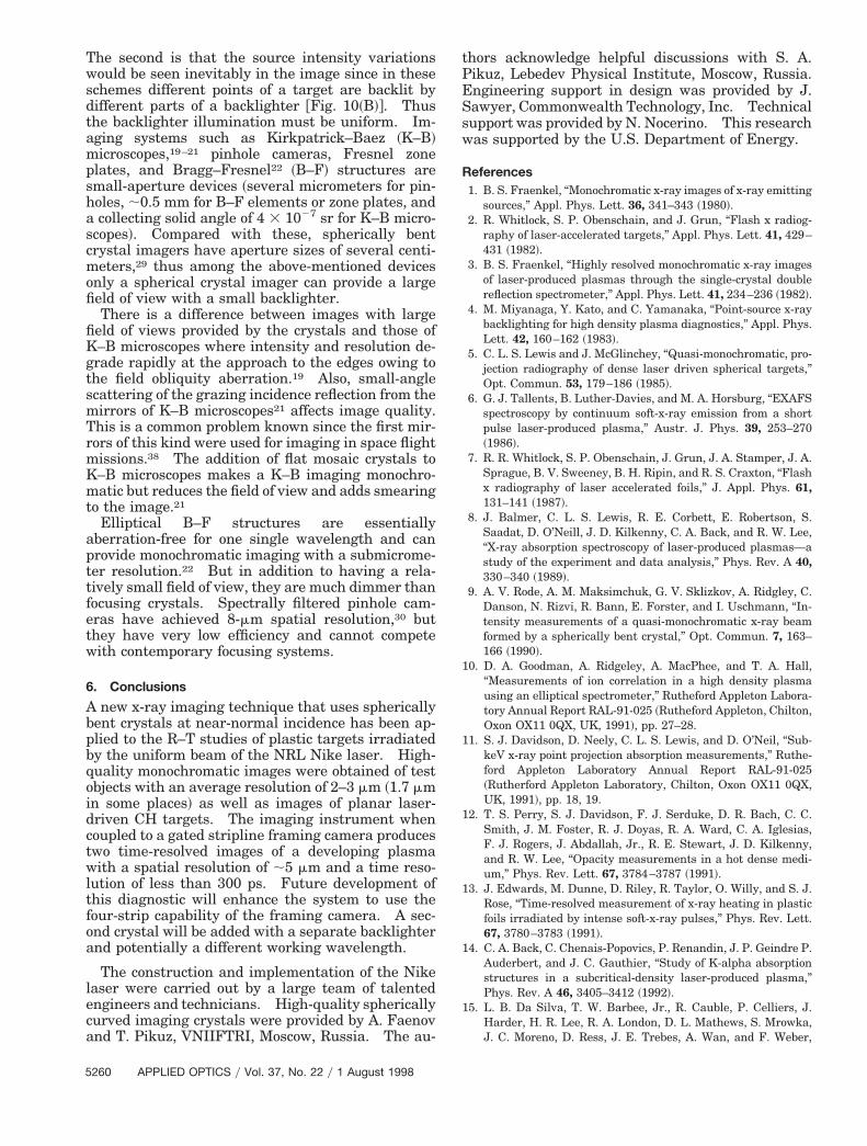
Figure 7 shows the same image as Fig. 6 taken with
Fig. 5. Test result of the large field of view achieved with the1000-lpi gold mesh and He-like Si backlighter ~x-ray film!.
Fig. 4. General scheme of the experiment and two crystal designsof the planned imaging system. Only one channel having twotime slots was used in the present experiment. The main targetis turned to be in a more favorable position for imaging.
1 August 1998 y Vol. 37, No. 22 y APPLIED OPTICS 5257
9sp
5
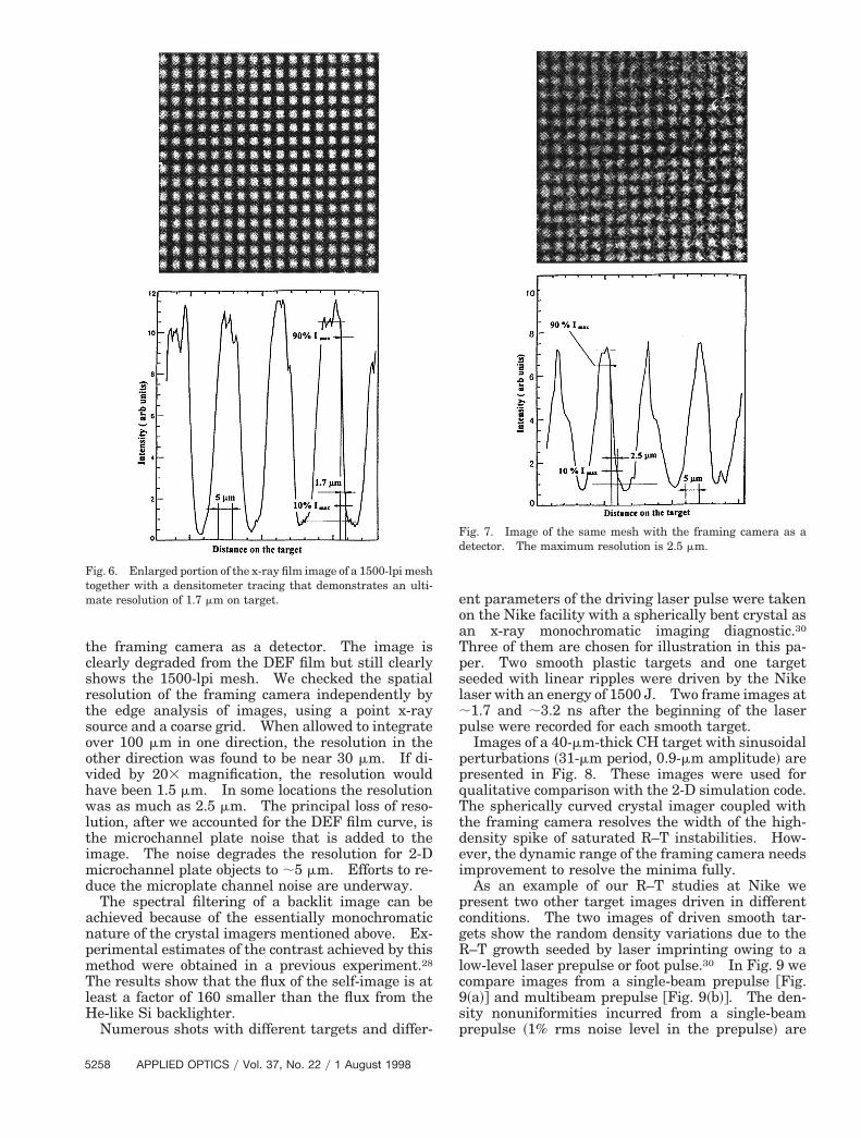
the framing camera as a detector. The image isclearly degraded from the DEF film but still clearlyshows the 1500-lpi mesh. We checked the spatialresolution of the framing camera independently bythe edge analysis of images, using a point x-raysource and a coarse grid. When allowed to integrateover 100 mm in one direction, the resolution in theother direction was found to be near 30 mm. If di-vided by 203 magnification, the resolution wouldhave been 1.5 mm. In some locations the resolutionwas as much as 2.5 mm. The principal loss of reso-lution, after we accounted for the DEF film curve, isthe microchannel plate noise that is added to theimage. The noise degrades the resolution for 2-Dmicrochannel plate objects to ;5 mm. Efforts to re-duce the microplate channel noise are underway.
The spectral filtering of a backlit image can beachieved because of the essentially monochromaticnature of the crystal imagers mentioned above. Ex-perimental estimates of the contrast achieved by thismethod were obtained in a previous experiment.28
The results show that the flux of the self-image is atleast a factor of 160 smaller than the flux from theHe-like Si backlighter.
Numerous shots with different targets and differ-
Fig. 6. Enlarged portion of the x-ray film image of a 1500-lpi meshtogether with a densitometer tracing that demonstrates an ulti-mate resolution of 1.7 mm on target.
258 APPLIED OPTICS y Vol. 37, No. 22 y 1 August 1998
ent parameters of the driving laser pulse were takenon the Nike facility with a spherically bent crystal asan x-ray monochromatic imaging diagnostic.30
Three of them are chosen for illustration in this pa-per. Two smooth plastic targets and one targetseeded with linear ripples were driven by the Nikelaser with an energy of 1500 J. Two frame images at;1.7 and ;3.2 ns after the beginning of the laserpulse were recorded for each smooth target.
Images of a 40-mm-thick CH target with sinusoidalperturbations ~31-mm period, 0.9-mm amplitude! arepresented in Fig. 8. These images were used forqualitative comparison with the 2-D simulation code.The spherically curved crystal imager coupled withthe framing camera resolves the width of the high-density spike of saturated R–T instabilities. How-ever, the dynamic range of the framing camera needsimprovement to resolve the minima fully.
As an example of our R–T studies at Nike wepresent two other target images driven in differentconditions. The two images of driven smooth tar-gets show the random density variations due to theR–T growth seeded by laser imprinting owing to alow-level laser prepulse or foot pulse.30 In Fig. 9 wecompare images from a single-beam prepulse @Fig.~a!# and multibeam prepulse @Fig. 9~b!#. The den-ity nonuniformities incurred from a single-beamrepulse ~1% rms noise level in the prepulse! are
Fig. 7. Image of the same mesh with the framing camera as adetector. The maximum resolution is 2.5 mm.
a
t
clearly visible at both times. The images from themultibeam prepulse case show smaller amplitudedensity variations attributed to the lower initial noiselevel of 0.15%. In the multibeam prepulse case theobserved variation at an earlier time is almost indis-tinguishable above the noise of the camera. A de-tailed analysis of these images and other R–Texperimental studies have been published.30
The spatial resolution of the spherically curvedcrystal imager is determined by the bending qualityand by normal optical aberrations that depend sig-nificantly on the Bragg angle. The image qualityanalysis shows that there are small local variations
Fig. 8. Comparison of the monochromatic ~1865-eV! image of asinusoidal mass perturbation, and the theoretical simulation. Tsinusoidal wavelength with 0.9-mm perturbation amplitude wasmplification of initially wide ripples are shown.
multibeam foot (smoothest foot)
(a)
(b)
Fig. 9. Monochromatic ~1865-eV! image of a driven smooth plasticarget with ~a! one beam prepulse and ~b! multibeam prepulse.
in the radius of curvature across the crystal surface.This was seen as a local difference in the test imagefocusing in two perpendicular directions. The crys-tal quality criterion therefore is the area of the imagewhere resolution meets the requirements of the ex-periment.
5. Comparison with Other Backlighting Imagers
One of the characteristics of any backlighting schemeis that the field of view with a small backlighter isdirectly proportional to the size of the input aperture@Fig. 10~A!#. Small-aperture devices require fairlybig backlighters for a wide field of view @see Fig.10~B!#. There are at least two drawbacks in usingbig-backlighter–small-aperture schemes. The firstis the obvious problem of creating a larger volume ofplasmas with high brightness in the x-ray region.
n plastic target with the initial 0.9-mm amplitude, 31-mm periodcceleration of a 43-mm-thick CH target perturbed with a 31-mmulated by use of FAST2D code.36,37 Significant narrowing and
Fig. 10. Comparison of ~A! the small source–big aperture and ~B!the big source–small aperture backlighting schemes. In ~A! thesource structure does not affect image uniformity since every pointof the target image uses radiation from the entire backlightersource. In ~B! different points of the object are backlit by differentparts of the backlighter source.
drivehe acalc
1 August 1998 y Vol. 37, No. 22 y APPLIED OPTICS 5259
ha
cm
idctwltfoa
leca
tPESsw
5
The second is that the source intensity variationswould be seen inevitably in the image since in theseschemes different points of a target are backlit bydifferent parts of a backlighter @Fig. 10~B!#. Thusthe backlighter illumination must be uniform. Im-aging systems such as Kirkpatrick–Baez ~K–B!microscopes,19–21 pinhole cameras, Fresnel zoneplates, and Bragg–Fresnel22 ~B–F! structures aresmall-aperture devices ~several micrometers for pin-
oles, ;0.5 mm for B–F elements or zone plates, andcollecting solid angle of 4 3 1027 sr for K–B micro-
scopes!. Compared with these, spherically bentrystal imagers have aperture sizes of several centi-eters,29 thus among the above-mentioned devices
only a spherical crystal imager can provide a largefield of view with a small backlighter.
There is a difference between images with largefield of views provided by the crystals and those ofK–B microscopes where intensity and resolution de-grade rapidly at the approach to the edges owing tothe field obliquity aberration.19 Also, small-anglescattering of the grazing incidence reflection from themirrors of K–B microscopes21 affects image quality.This is a common problem known since the first mir-rors of this kind were used for imaging in space flightmissions.38 The addition of flat mosaic crystals toK–B microscopes makes a K–B imaging monochro-matic but reduces the field of view and adds smearingto the image.21
Elliptical B–F structures are essentiallyaberration-free for one single wavelength and canprovide monochromatic imaging with a submicrome-ter resolution.22 But in addition to having a rela-tively small field of view, they are much dimmer thanfocusing crystals. Spectrally filtered pinhole cam-eras have achieved 8-mm spatial resolution,30 butthey have very low efficiency and cannot competewith contemporary focusing systems.
6. Conclusions
A new x-ray imaging technique that uses sphericallybent crystals at near-normal incidence has been ap-plied to the R–T studies of plastic targets irradiatedby the uniform beam of the NRL Nike laser. High-quality monochromatic images were obtained of testobjects with an average resolution of 2–3 mm ~1.7 mmn some places! as well as images of planar laser-riven CH targets. The imaging instrument whenoupled to a gated stripline framing camera produceswo time-resolved images of a developing plasmaith a spatial resolution of ;5 mm and a time reso-
ution of less than 300 ps. Future development ofhis diagnostic will enhance the system to use theour-strip capability of the framing camera. A sec-nd crystal will be added with a separate backlighternd potentially a different working wavelength.
The construction and implementation of the Nikeaser were carried out by a large team of talentedngineers and technicians. High-quality sphericallyurved imaging crystals were provided by A. Faenovnd T. Pikuz, VNIIFTRI, Moscow, Russia. The au-
260 APPLIED OPTICS y Vol. 37, No. 22 y 1 August 1998
hors acknowledge helpful discussions with S. A.ikuz, Lebedev Physical Institute, Moscow, Russia.ngineering support in design was provided by J.awyer, Commonwealth Technology, Inc. Technicalupport was provided by N. Nocerino. This researchas supported by the U.S. Department of Energy.
References1. B. S. Fraenkel, “Monochromatic x-ray images of x-ray emitting
sources,” Appl. Phys. Lett. 36, 341–343 ~1980!.2. R. Whitlock, S. P. Obenschain, and J. Grun, “Flash x radiog-
raphy of laser-accelerated targets,” Appl. Phys. Lett. 41, 429–431 ~1982!.
3. B. S. Fraenkel, “Highly resolved monochromatic x-ray imagesof laser-produced plasmas through the single-crystal doublereflection spectrometer,” Appl. Phys. Lett. 41, 234–236 ~1982!.
4. M. Miyanaga, Y. Kato, and C. Yamanaka, “Point-source x-raybacklighting for high density plasma diagnostics,” Appl. Phys.Lett. 42, 160–162 ~1983!.
5. C. L. S. Lewis and J. McGlinchey, “Quasi-monochromatic, pro-jection radiography of dense laser driven spherical targets,”Opt. Commun. 53, 179–186 ~1985!.
6. G. J. Tallents, B. Luther-Davies, and M. A. Horsburg, “EXAFSspectroscopy by continuum soft-x-ray emission from a shortpulse laser-produced plasma,” Austr. J. Phys. 39, 253–270~1986!.
7. R. R. Whitlock, S. P. Obenschain, J. Grun, J. A. Stamper, J. A.Sprague, B. V. Sweeney, B. H. Ripin, and R. S. Craxton, “Flashx radiography of laser accelerated foils,” J. Appl. Phys. 61,131–141 ~1987!.
8. J. Balmer, C. L. S. Lewis, R. E. Corbett, E. Robertson, S.Saadat, D. O’Neill, J. D. Kilkenny, C. A. Back, and R. W. Lee,“X-ray absorption spectroscopy of laser-produced plasmas—astudy of the experiment and data analysis,” Phys. Rev. A 40,330–340 ~1989!.
9. A. V. Rode, A. M. Maksimchuk, G. V. Sklizkov, A. Ridgley, C.Danson, N. Rizvi, R. Bann, E. Forster, and I. Uschmann, “In-tensity measurements of a quasi-monochromatic x-ray beamformed by a spherically bent crystal,” Opt. Commun. 7, 163–166 ~1990!.
10. D. A. Goodman, A. Ridgeley, A. MacPhee, and T. A. Hall,“Measurements of ion correlation in a high density plasmausing an elliptical spectrometer,” Rutheford Appleton Labora-tory Annual Report RAL-91-025 ~Rutheford Appleton, Chilton,Oxon OX11 0QX, UK, 1991!, pp. 27–28.
11. S. J. Davidson, D. Neely, C. L. S. Lewis, and D. O’Neil, “Sub-keV x-ray point projection absorption measurements,” Ruthe-ford Appleton Laboratory Annual Report RAL-91-025~Rutherford Appleton Laboratory, Chilton, Oxon OX11 0QX,UK, 1991!, pp. 18, 19.
12. T. S. Perry, S. J. Davidson, F. J. Serduke, D. R. Bach, C. C.Smith, J. M. Foster, R. J. Doyas, R. A. Ward, C. A. Iglesias,F. J. Rogers, J. Abdallah, Jr., R. E. Stewart, J. D. Kilkenny,and R. W. Lee, “Opacity measurements in a hot dense medi-um,” Phys. Rev. Lett. 67, 3784–3787 ~1991!.
13. J. Edwards, M. Dunne, D. Riley, R. Taylor, O. Willy, and S. J.Rose, “Time-resolved measurement of x-ray heating in plasticfoils irradiated by intense soft-x-ray pulses,” Phys. Rev. Lett.67, 3780–3783 ~1991!.
14. C. A. Back, C. Chenais-Popovics, P. Renandin, J. P. Geindre P.Auderbert, and J. C. Gauthier, “Study of K-alpha absorptionstructures in a subcritical-density laser-produced plasma,”Phys. Rev. A 46, 3405–3412 ~1992!.
15. L. B. Da Silva, T. W. Barbee, Jr., R. Cauble, P. Celliers, J.Harder, H. R. Lee, R. A. London, D. L. Mathews, S. Mrowka,J. C. Moreno, D. Ress, J. E. Trebes, A. Wan, and F. Weber,
“X-ray lasers for high density plasma diagnostics,” Rev. Sci.
1
1
1
1
28. C. Brown, J. Seely, U. Feldman, S. Obenschain, S. Bodner, C.
Instrum. 66, 574–578 ~1995!.
6. R. Cauble, L. B. Da Silva, T. W. Barbee, Jr., P. Celliers, J. C.Moreno, and A. S. Wan, “Micron resolution radiography oflaser-accelerated and x-ray heated foils with an x-ray laser,”Phys. Rev. Lett. 74, 3816–3819 ~1995!.
7. L. B. Da Silva, T. W. Barbee, Jr., R. Cauble, P. Celliers, D.Ciarlo, S. Libby, R. A. London, D. Mathews, S. Mrowka, J. C.Moreno, D. Ress, J. E. Trebes, A. S. Wan, and F. Weber,“Electron density measurements of high density plasmas us-ing soft-x-ray laser interferometry,” Phys. Rev. Lett. 74, 3991–3994 ~1995!.
8. R. J. Taylor, J. P. Dahlburg, A. Iwase, J. H. Gardner, D. E.Fyfe, and O. Willi, “Measurements and stimulation of laserimprinting and consequent Rayleigh–Taylor growth,” Phys.Rev. Lett. 76, 1643–1646 ~1996!.
9. D. Schirmann, “Advances in laser created plasma diagnostics,”Plasma Phys. Rep. 20, 113–121 ~1994!.
20. F. J. Marshall and O. Su, “Quantitative measurements withx-ray microscopes in laser fusion experiments,” Rev. Sci. In-strum. 66, 725–727 ~1995!.
21. F. J. Marshall and J. A. Oertel, “A framed monochromatic x-raymicroscope for ICF,” Rev. Sci. Instrum. 68, 735–739 ~1997!.
22. A. Erko, Yu. Agafonov, L. A. Panchenko, A. Yakshin, P. Chev-allier, P. Dhez, and F. Legrand, “Elliptical multilayer Bragg–Fresnel lenses with submicrometer spatial resolution for xrays,” Opt. Commun. 106, 146–150 ~1994!.
23. S. A. Pikuz, T. A. Shelkovenko, V. M. Romanova, D. A. Ham-mer, A. Ya. Faenov, V. Dyakin, and T. A. Pikuz, “Monochro-matic x-ray probing of an ultradense plasma,” JETP Lett. 61,638–644 ~1995!.
24. S. A. Pikuz, T. A. Shelkovenko, V. M. Romanova, D. A. Ham-mer, A. Ya. Faenov, V. A. Dyakin, and T. A. Pikuz, “High-luminosity monochromatic x-ray backlighting usingincoherent plasma source to study extremely dense plasmas,”in Soft X-Ray Lasers and Applications, J. J. Rocca and P. L.Hagelstein, eds., Proc. SPIE 2520, 330–341 ~1995!.
25. T. A. Pikuz, A. Ya. Faenov, S. A. Pikuz, V. M. Romanova, andT. A. Shelkovenko, “Bragg x-ray optics for imaging spectros-copy of plasma microsources,” J. X-ray Sci. Technol. 5, 323–340~1995!.
26. Y. Aglitskiy, T. Lehecka, A. Deniz, J. Hardgrove, J. Seely, C.Brown, U. Feldman, C. Pawley, K. Gerber, S. Bodner, S. Oben-schain, R. Lehmerg, E. McLean, M. Pronko, J. Sethian, A.Schmitt, C. Sullivan, G. Holland, and M. Laming, “X-ray emis-sion from plasmas created by smoothed KrF laser irradiation,”Phys. Plasmas 3, 3438–3447 ~1996!.
27. C. Brown, J. Seely, U. Feldman, S. Obenschain, S. Bodner, C.Pawely, K. Gerber, V. Serlin, J. Sethian, Y. Aglitskiy, T. Le-hecka, and G. Holland, “X-ray imaging of targets irradiated bythe Nike KrF laser,” Rev. Sci. Instrum. 68, 1099–1102 ~1997!.
Pawley, K. Gerber, J. Sethian, A. Mostovich, Y. Aglitskiy, T.Lehecka, and G. Holland, “High-resolution x-ray imaging ofplanar foils irradiated by the Nike KrF laser,” Phys. Plasmas4, 1397–1401 ~1997!.
29. M. Sanchez del Rio, A. Ya. Faenov, V. M. Dyakin, T. A. Pikuz,S. A. Pikuz, V. M. Romanova, and T. A. Shelkovenko, “Ray-tracing for a monochromatic x-ray backlighting scheme basedon spherically bent crystal,” Phys. Sci. 55, 735–750 ~1997!.
30. C. J. Pawley, K. Gerber, R. H. Lehmberg, E. A. McLean, A. N.Mostovych, S. P. Obenschain, J. D. Sethian, V. Serlin, J. A.Stamper, C. A. Sullivan, S. E. Bodner, D. Colombant, J. P.Dahlburg, A. J. Schmitt, J. H. Gardner, C. Brown, J. F. Seely,T. Lehecka, Y. Aglitskiy, A. V. Deniz, Y. Chan, N. Metzler, andM. Klapisch, “Measurements of laser-imprinted perturbationsand Rayleigh–Taylor growth with the Nile KrF laser,” Phys.Plasmas 4, 1969–1977 ~1997!.
31. S. A. Pikuz, T. A. Shelkovenko, V. M. Romanova, D. A. Ham-mer, A. Ya. Faenov, V. A. Dyakin, and T. A. Pikuz, “Highluminosity monochromatic x-ray backlighting using an inco-herent plasma source to study extremely dense plasmas,” Rev.Sci. Instrum. 68, 740–744 ~1997!.
32. R. H. Lehmberg and S. P. Obenschain, “Use of induced spatialincoherence for uniform illumination of laser fusion targets,”Opt. Commun. 46, 27–31 ~1983!.
33. R. H. Lehmberg and J. Goldhar, “Use of incoherence to producesmooth and controllable irradiation profiles with KrF fusionlasers,” Fusion Technol. 11, 532–541 ~1987!.
34. T. Lehecka, R. Lehmberg, A. Deniz, K. Gerber, S. Obenschain,C. Pawley, M. Pronko, and C. Sullivan, “Production of highenergy, uniform focal profiles with the Nike laser,” Opt. Com-mun. 117, 485–491 ~1995!.
35. S. P. Obenschain, S. Bodner, D. Colombant, K. Gerber, R.Lehmberg, E. McLean, A. Mostovych, M. Pronko, C. Pawely, A.Schmitt, J. Sethian, V. Serlin, J. Stamper, C. Sullivan, J.Dahlburg, J. Gardner, Y. Chan, A. Deniz, J. Hardgrove, T.Lehecka, and M. Klapisch, “The Nike KrF facility: perfor-mance and initial target experiments,” Phys. Plasmas 3,2098–2107 ~1996!.
36. M. H. Emery, J. H. Gardner, and J. P. Boris, “Nonlinear as-pects of hydrodynamic instabilities in laser ablation,” Appl.Phys. Lett. 41, 808–810 ~1982!.
37. J. P. Dahlburg, M. Klapisch, J. H. Gardner, C. R. DeVore, A. J.Schmitt, and A. Bar-Shalom, “Radiating plasma structures inablating laser-produced plasmas,” J. Quant. Spectrosc. Radiat.Transfer 54, 113–121 ~1995!.
38. S. Tsuneta, L. Acton, M. Bruner, J. Lemen, W. Brown, R.Caravalho, R. Catura, S. Freeland, B. Jurcevich, M. Morrison,Y. Ogawara, T. Hirayama, and J. Owens, “The soft x-ray tele-scope for the SOLAR-A mission,” Sol. Phys. 136, 37–67 ~1991!.
1 August 1998 y Vol. 37, No. 22 y APPLIED OPTICS 5261