A high-resolution spectroscopic facility, consisting of a 6.65-m vertical dispersion off-plane Eagle spectro-graph/monochromator and a unique predisperser system of zero-dispersion type, has been designed and
constructed at the Photon Factory. A description is given of design principle, optical system, mechanicalarrangement, vacuum system, control system, and performance in the spectrograph mode. The resolvingpower was estimated from the separation between two closely lying lines of Ar I at -79 nmin the seventh orderto be >2.5 X 10 5 -the highest resolving power ever demonstrated for this spectral region.
1. Introduction
A new facility has been installed at the Photon Fac-tory (PF) in the National Laboratory for High EnergyPhysics (KEK) located in Tsukuba to provide thespectroscopic community with a very high-resolutionspectroscopic instrument for research in atomic andmolecular science using synchrotron radiation (SR).In early 1980, work was begun by the authors on selec-tion of a mounting suitable for and the means ofachieving a high resolution of -2 X 10⁵ in the 40-200-nm region. These studies were followed by basic de-sign work right after reaching the decision (1) to adopta vertical dispersion-type off-plane Eagle mounting1 2
of 6-m class because of its proven high-resolution capa-bility2 -4 and compatibility with the polarization char-acteristics of SR, (2) to incorporate three modes ofoperation, i.e., spectrograph mode, focal plane scan-
Kenji Ito is with National Laboratory for High Energy Physics,Photon Factory, Oho-machi, Tsukuba-gun, Ibaraki 305, Japan; T.Namioka is with Tohoku University, Research Institute for Scientif-ic Measurements, Katahira, Sendai 980, Japan; T. Sasaki is withOsaka University, Faculty of Engineering Science, Toyonaka, Osaka530, Japan; K. Goto is with Shinshu University, Department ofPrecision Engineering, Wakasato, Nagano 380, Japan; T. Katayamais with Defense Academy, Department of Mathematics & Physics,Hashirimizu, Yokosuka 239, Japan; M. Koike is with ShimadzuCorporation, Nakagyo-ku, Kyoto 604, Japan; and the other authorsare with University of Tsukuba, Sakura-mura, Niihari-gun, Ibaraki305, Japan.
ning mode, and monochromator mode, in the instru-ment, and (3) to utilize high spectral orders because ahigh-quality 6.65-m grating with -4000 grooves/mmwas not available. Basic designs of the 6.65-m verticaldispersion-type off-plane Eagle spectrograph/mono-chromator (denoted 6VOPE), the predisperser systemwhich was devised specifically for the facility to pro-vide a unique zero-dispersion order-sorting capability,and the associated beam lines were completed inSpring 1981.
The instrument was then constructed by ShimadzuCorp. and installed on the beam line 12-B at the PF in1983. After careful adjustments and modifications,the facility became operational and attained in thespectrograph mode a resolving power >2.5 X 10⁵ at-79 nm-the highest resolving power ever demon-strated for this spectral region. While testing of6VOPE is still in progress for the focal plane scanningand monochromator modes, it is anticipated that atleast the former mode will closely approach the resultsalready obtained with the spectrograph mode.
II. Design Criteria and Design Principle
The requirements imposed on the design of the6VOPE facility are (1) to have a resolving power of -2X 10⁵ in high spectral orders of a 1200-groove/mmgrating in the 40-200 nm wavelength region with theaid of an efficient predisperser system, (2) to providethree modes of operation, i.e., spectrograph mode[with one 25.4-cm (10-in.) photographic plate], focalplane scanning mode (with a scanning range of 250 mmon the Rowland cylinder), and monochromator mode(with simultaneous translation and rotation of a first-order grating for a moderate resolution), (3) to have SRacceptance angles of 3.6 mrad in the vertical plane and
Fig.1. Schematic of the optical system for illustrating the principleof the predisperser: M, plane mirror; G1 and G2, foregratings; G3,
main grating.
5 mrad in the horizontal plane, (4) to use optical com-ponents having plane and spherical surfaces only, (5)to provide at least a 1-m long free space in front of themain entrance slit for inserting an experimental devicesuch as a heat pipe, and (6) to meet a number of site-imposed constraints, major ones of which are the mini-mum allowable distance of -11 m between the SRsource point and the first mirror for x-ray cutoff, in-stallation of the main body of 6VOPE on the mezza-nine floor, which is located 2.8 m above the groundfloor and 1.6 m above the SR beam line, the clearancerequired between 6VOPE and other experimental sta-tions, etc.
We examined various optical systems within theframework of the requirements outlined above anddecided to take, as the basic arrangement, a systemconsisting of an x-ray cutoff plane mirror M, a predis-perser with two concave gratings, G and G2, and a6.65-m 1200-groove/mm concave grating G3 in the off-plane Eagle mounting (Fig. 1). The initial design pa-rameters were then determined5 from the first-orderequations, such as the conventional focal equations forG1, G2, and G3, the conditions for coma elimination andzero dispersion for G1 and G2, and simple geometricalrelations for f/No. matching together with the givensite-imposed constraints. By the design parameterswe mean here the distances between the successiveoptical elements in the train, the angles of incidence,reflection, and diffraction, and the ruling parametersand radii of G1 and G2. The preliminary design wasfurther refined by applying a nonlinear optimizationmethod in combination with a ray tracing method to aproperly chosen merit function of the system.5
11. Predisperser System
Two types of grating predisperser have been suc-cessfully used with conventional VUV laboratorysources: use of a coarse plane grating 6 and of a coarseconcave grating,7 both being placed in front of theentrance slit of a spectrograph and used in grazingincidence. However, these predispersers do not havecontrol over the bandpass, and this becomes the deci-sive defect when they are used with a vertical disper-sion-type instrument and horizontal linelike SRsource.
This situation is clearly illustrated in Fig. 2, wherethe predisperser of Douglas and Herzberg7 is taken asan example. In the arrangement of Fig. 2(a) we con-sider the profiles of the +1st-order spectrum of 95, 100,and 105 nm formed on the entrance slit S by the
1 61 .I~366.5mm
G
+1 ORDER D)
611.8mm 1OnmXZ95nmS
(a)
11 lO~n~1 00nm11 100nm E 36 -95nm 105nm
LI In
Z
H ~ ~ ~ ~ H
< 5.5 t 115nm i 16 ii
rX O I kl O
0 6mm a 0 4mmDISTANCE ACROSS S DISTANCE ACROSS S
(b) (C)
Fig. 2. Predisperser of grazing incidence type7 and its expectedperformance: (a) schematic of the predisperser: L, light source; G,concave grating with 135 grooves/mm, 3-m radius of curvature, and aruled area of 30 (H) X 60 (W) mm2 ; S entrance slit of the mainspectrograph; (b), (c) computed line profiles of 95-, 100-, and 105-nmradiation in the plane of the slit S, respectively, for a 4- X 4-mm 2
source and a 0.4- X 4-mm 2 source.
foregrating G with 135 grooves/mm, a radius of curva-ture of 3 m, and ruled area of 30 (H) X 60 (W) mm2.Figure 2(b) shows the spectral images of a 4- X 4-mm 2
light source, and Fig. 2(c) shows those of a 0.4- X 4-mm2 source, whose long side is parallel to the entranceslit. These profiles were all computed from the spotdiagrams in the plane of the entrance slit, and the totalintensity of each spectral image was normalized tounity. Figure 2(b) shows that the images of 95, 100,and 105 nm overlap one another in the slit opening,suggesting that order separation is possible (althoughonly 0.1% of rays pass through the slit of 20 ,m X 10mm). By contrast, the predisperser loses its functioncompletely, as is seen in Fig. 2(c), for a linelike SRsource parallel to the entrance slit.
One possible solution to the problem is to use twovertical dispersion-type monochromators of constantdeviation in the zero-dispersion mode, the first and thesecond monochromator being composed of the SRsource point P the first concave foregrating G, andthe intermediate slit S, and of SI, the second concaveforegrating G2, and the entrance slit S2 of the mainspectrograph, respectively (Fig. 1). With this ar-rangement, a desired wavelength portion of SR can besorted out by simple rotation of G1 and adjustment ofthe width of S, and the properly filtered SR can becounterdispersed to neutralize the dispersion and fo-cused on S2 by simple rotation of G2. This zero-dis-persion scheme would provide (1) a relatively highgeometrical transmission, say 15% or more, (2) thecapability of selecting any center wavelength in the40-200-nm region and a desired bandpass in a simplemanner, and (3) a bandpass wide enough to cover one25.4-cm photographic plate in any spectral order of themain grating G3, from the first through the fourteenthorder.
To realize this scheme it was found to be essential touse 200-groove/mm concave gratings with variable
Fig. 3. Optical system of the 6VOPE facility: P source point; SR,synchrotron radiation; M, SiC plane mirror; G, G2, foregratings inthe predisperser system; Ml M 2, concave mirrors whose radii ofcurvature and dimensions are the same as those of G, and G2; Sl,intermediate slit; S2, entrance slit of 6VOPE; G3 /G3 ', main gratings
of 6VOPE.
spacings and straight grooves for GI and G2. In view ofpractical problems in fabricating a grating blank thathas exactly the same radius of curvature as designed,we further optimized the designed predisperser systemby taking the values of the radii of curvature of manu-facturer's standard mirrors which were the closest tothe designed values for G1 and G2. Finally, the expect-ed performance of the predisperser system thus de-signed was thoroughly examined by constructing spotdiagrams at the individual optical elements and bysimulating the spectral image profiles at the main en-trance slit S2. The result confirmed that the designedsystem possessed all the features required for efficientorder sorting.
IV. Optical System
The optical system of the 6VOPE facility thus de-signed is schematically shown in Fig. 3. SR from thesource point P travels 11,300 mm to the water-cooledx-ray cutoff mirror M, where it is deflected downwardby a 20° angle onto the first foregrating G1. This beamis dispersed upward by GI located 13,500 mm from Pand 801 mm below the plane of the electron orbit.Only the desired wavelength portion of the diffracted
SR is permitted to pass through the intermediate slitSi situated 2042 mm directly above G1 . The filteredSR is counterdispersed and focused onto the mainentrance slit S2 of 6VOPE by the second foregrating G2placed 3751 mm above G1. The beam thus sorted outis finally dispersed by the main grating G3, which isblazed for 550 nm, to form a high-order spectrum alonga photographic plate of 5-cm (2 in.) X 25.4 cm on thefocal plane. This optical system accepts 5 mrad (hori-zontal) X 3.6 mrad (vertical) of SR from the source andmatches all the f/Nos. of the elements.
Table I summarizes the specifications of the opticalelements used in the facility. The foremirror M is aCVD silicon carbide mirror supplied by Toshiba Ce-ramics. A silicon carbide layer several hundred mi-crons thick was formed on a carbon graphite substrateby means of chemical vapor deposition. The blanksfor G1 and G2 and the mirror Ml and M2 were polishedby Nikon. Possible errors in the absolute values oftheir radii of curvature are well within 1%. The fore-gratings G1 amd G2 were ruled on the Nikon's blanksby Hitachi by varying the groove spacing in accordancewith our design parameters. The main gratings G3and G3' (1200 grooves/mm) were supplied by Bausch &Lomb. The main grating G3' (4800 grooves/mm) wasruled by Hyperfine, Inc. on combined commission ofthe KEK, University of Maryland, and National Sci-ence Foundation.8
6VOPE can be operated in the spectrograph, focalplane scanning, or the monochromator mode. Con-version from the spectrograph mode to the focal planescanning mode requires no alteration in the opticalsystem, whereas conversion to the monochromatormode necessitates interchange of the high-order grat-ing G3 with one of the first-order gratings G3' and,usually, interchange of G1 and G2 with M1 and M2.The reasons for these interchanges are that one cannotachieve mechanical accuracies in simultaneous rota-tion and translation of G3 to match the high resolutionexhibited by G3 fixed in position and that one canutilize more SR using mirrors than using zero orders ofthe foregratings.
The centers of P, M, G1, Si, G2, and S2 lie in the samevertical plane. The center of G3 lies in this vertical
Table 1. Optical Elements of the 6VOPE Facility
Optical Dimensions (mm) Radius of Groove density Blaze wavelength/Element Type Material Effective area (mm 2 ) curvature (mm) (grooves/mm) blaze angle
M Plane mirror SiC 100 (W) X 280 (H) X 40 (t) - -80 (W) X 280 (H)
Gla Concave grating Pyrex 110,p X 20 (t) 4321 200 74 nm/0.52'(replica) Pt-coated 70 (W) X 75 (H) Variable spacingb
G2a Concave grating Pyrex 110,p X 20 (t) 2188.5 204 70 nm/0.58o(replica) Pt-coated 70 (W) X 60 (H) Variable spacingb
G3 Concave grating BK7 2101) X 30 (t) 6650 1200 550 nm/19016'(replica) Os-coated 175 (W) X 100 (H)
G3' Concave grating BK7 2101) X 30 (t) 6650 1200 150 nm/510'(replica) Pt-coated 175 (W) X 100 (H)
G3' Concave grating Quartz 180,1 X 30 (t) 6650 4800 90 nm(replica) Os-coated 125 (W) X 110 (H)
a In the monochromator mode, G, and G2 are replaced by concave mirrors Ml and M 2 whose radii of curvature and dimensions are the sameas those of G, and G2-
b Parameters for variable spacings are given in Ref. 5.
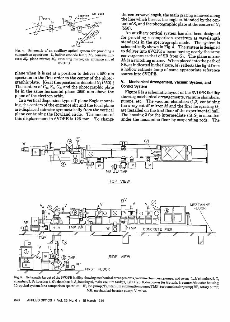
Fig. 4. Schematic of an auxiliary optical system for providing acomparison spectrum: L, hollow cathode lamp; Mc, concave mir-rors; M, plane mirror; M3, switching mirror; S2, entrance slit of
6VOPE.
plane when it is set at a position to deliver a 550-nmspectrum in the first order to the center of the photo-graphic plate. [G3 at this position is denoted G3 (550).]The centers of G2, S2, G3, and the photographic platelie in the same horizontal plane 2950 mm above theplane of the electron orbit.
In a vertical dispersion-type off-plane Eagle mount-ing, the centers of the entrance slit and the focal planeare displaced sidewise symmetrically from the verticalplane containing the Rowland circle. The amount ofthis displacement in 6VOPE is 125 mm. To change
the center wavelength, the main grating is moved alongthe line which bisects the angle subtended by the cen-ters of S2 and the photographic plate at the center of G3(550).
An auxiliary optical system has also been designedfor providing a comparison spectrum as wavelengthstandards in the spectrograph mode. The system isschematically shown in Fig. 4. The system is designedto deliver into 6VOPE a beam having nearly the sameconvergence as that of SR from G2. The plane mirrorM3is a switching mirror. When placed into the path ofSR, as indicated in the figure, M3 reflects the light froma hollow cathode lamp of some appropriate referencesource into 6VOPE.
V. Mechanical Arrangement, Vacuum System, andControl System
Figure 5 is a schematic layout of the 6VOPE facilityshowing mechanical arrangements, vacuum chambers,pumps, etc. The vacuum chambers (1,2) containingthe x-ray cutoff mirror M and the first foregrating G,are installed on the first floor of the experimental hall.The housing 3 for the intermediate slit Si is mountedunder the mezzanine floor by suspending rods. The
RP_ 1R
TOP VIEW
V
V MEZZANINEFLOOR
RP
'MP SIDE VIEW
RP
FIRST FLOOR
Fig.5. Schematic layout of the 6VOPE facility showing mechanical arrangements, vacuum chambers, pumps, and so on: 1, M chamber,2, Gchamber; 3, S housing; 4, G2 chamber; 5, S2 housing; 6, main vacuum tank; 7, light trap; 8, dust cover for G3 tank, 9, camera/detector housing;10, optical system for a comparison spectrum: IP, ion pump; Ti, titanium sublimation pump; TMP, turbomolecular pump; RP, rotary pump;
Fig. 6. G chamber and S, housing on the first floor.
chamber 4 containing the second foregrating G2 andthe body of 6VOPE (5-9) are supported on a massivereinforced concrete pier cast directly on the mezzaninefloor.
The beam line and the predisperser system are ul-trahigh vacuum compatible, but 6VOPE utilizes anumber of Viton 0-rings to facilitate operations ofrather complex mechanisms required for the instru-mentf's function. The system is equipped with ionpumps (IP), a Ti-sublimation pump (Ti), turbomo-lecular pumps (TMP) backed by a mechanical booster(MB), and/or rotary pumps (RP), pneumatic valves(V), and other usual vacuum components.
Adjustments and operations of the foregratings,main grating, cassette tilt, and scanning mechanismsare all under computer control.
A. Mechanical Arrangement
The x-ray cutoff mirror M, made of CVD siliconcarbide, is water-cooled and mounted on a z-O-0 goni-ometer inside chamber 1. Its position can be adjustedfrom the mezzanine floor by means of three steppingmotors remotely controlled. The mechanisms forthree-axis rotation of the foregratings G, and G2 aremounted on the outside of the respective vacuumchambers 2 and 4. G and G2 can be scanned bystepping motors over a +3' angle range around thezeroth-order position with a minimum increment of0.275 s of arc/step. This permits selection of anycenter wavelength in a 0-350-nm range with an accura-cy of -0.05 nm. The width of S, can easily be adjustedmanually from the mezzanine floor to provide a de-sired bandpass up to 15 nm wide. Adjustments of M,G1, G2, and Si can be made without breaking vacuum.In Fig. 6 is shown a view of the G, chamber and the Sihousing on the first floor.
6VOPE consists of the entrance slit box 5, threevacuum tanks 6, main grating tank (inside the dustcover 8), rear bulkhead (also inside 8), and camera/de-tector housing 9. Vacuum feedthroughs are providedon the sidewall of 5 for operations of slit seal, slit tilt,and slit-height-limiting mask. No feedthrough is,however, provided for slit width adjustment becausewe found, in the initial stage of focus adjustment, aslight mechanical interference between the slit mecha-nisms for width and tilt adjustments. Interchange-able fixed slits and an adjustable slit are now in usewithout outside control. The slit box 5 can be separat-ed from the tank 6 and G2 chamber 4, respectively, by agate valve and window valve, which was found conve-nient for optical alignment test. This allows evacua-tion of 5 independently of the other sections. Thebeam line between 4 and 5 provides two ports: onewith a beam-switching plane mirror (M3 in Fig. 4) andthe other with a beam splitter. The former is forintroducing light from a comparison line source 10 into6VOPE and the latter for monitoring the number den-sity in a high-temperature vapor cell experiment.8
The vacuum tanks 6 are separated by bellows sec-tions from all the other sections of 6VOPE and theturbomolecular pumps, which are rigidly supportedfrom the mezzanine floor. A small hornlike structure7 on the tank is a light trap for zeroth-order reflectionfrom the grating set for 550 nm. Light baffles made ofaluminum are also provided inside the tanks to reducethe amount of stray light.
The main grating G3 (or G3') is mounted kinemati-cally in a holder, which is, in turn, placed in gimbals.Alignment of the ruling direction is made manually inair. Rotation of G3 (or G3') is achieved by means of anactuator rod driven by a stepping motor mounted out-side the tank. The angle of incidence at the gratingcan be varied from -1 to 23° at a rate of 0.056 s ofarc/step (or 4 X 10⁻⁴ nm/step in terms of first-orderwavelength). The G3 tank is separated from both themain tanks 6 and the fixed rear bulkhead by identicallarge bellows sections, as is seen in Fig. 7. This tankcan be translated along external (to the vacuum) waysby an external drive mechanism with the forces on thedriven tank produced by vacuum in the bellows sec-tions canceling. The G3 tank can be translated over adistance of -530 mm at a rate of 0.1,gm/step by threehigh-precision ball screws driven simultaneously by astepping motor through a timing belt. This guaran-tees, to a very high degree of accuracy, the movementof the G3 tank without yawing and pitching. Whenneeded, the G3 tank can be translated at high speed byan induction motor. Manual drive is also possible.Simultaneous translation and rotation of G3' requiredin the monochromator mode is realized by softwarelinkage instead of hardware linkage.
The camera/detector housing 9 contains variouscomplex mechanisms for cassette handling, mask con-trol, and focal plane scanning. These mechanismspermit the cassette holder, mask, and exit-slit/absorp-tion-cell/photomultiplier unit (denoted exit-slit unitfor brevity) to translate and rotate. The cassette hold-
Fig. 7. 6VOPE facility from the end of the G3 chamber.
er and the exit-slit unit are rigidly connected in astainless steel frame, so that either one of them can bebrought to the focal position by moving them sidewise(horizontally). This allows conversion of the spectro-graph mode to the focal plane scanning mode or re-verse conversion in a simple manner without breakingvacuum. Figure 8 shows a view of the 6VOPE facilityfrom the G2 chamber end and the camera/detectorhousing.
The daylight loading-type cassette can be insertedfrom the top side of 9 into the cassette holder placedinside the housing. By moving the cassette holdersidewise (horizontally) toward the focus position, acatch automatically pulls the dark slide out of thecassette, making it ready to photograph. The cassetteis rotated by the command of the computer until theplane of photographic plate coincides with the Row-land cylinder. A series of spectra can be taken on oneplate by moving the cassette holder sidewise a properdistance repeatedly after each exposure, while themask limits the height of the spectral lines to be photo-graphed. To put a comparison spectrum along side anabsorption spectrum, the mask is moved sidewise aproper distance while the cassette holder remains un-changed. On finishing exposures, the dark slide canbe put back into the cassette by making the cassetteholder upright and moving it back sidewise to theoriginal position. Tilt of the cassette holder can bevaried with the aid of the computer from vertical direc-tion to a 23° angle at a rate of 1.5 s of arc/step.
Fig. 8. 6VOPE facility from the G2 chamber side.
In the focal plan scanning mode, it is important todirect the exit-slit unit always toward the center of thegrating while the unit moves along the focal curve onthe Rowland cylinder. This is achieved by using anactuator rod for rotation and a lead screw for transla-tion (both driven by stepping motors), both of whichare coupled by software linkage. The exit-slit unit canbe moved over a distance of 260 mm along the focalcurve at a rate of 2um/step (or 2.5 X 10⁻⁴ nm/step interms of first-order wavelength).
All the driving mechanisms are provided with a pairof limit switches as a safety measure against accidentaloverrun.
Working with the PF electron storage ring requiresmaintaining the pressure in the M chamber (1 in Fig. 5)at -5 X 10⁻⁹ Torr under working conditions. To meetthis requirement, the entire beam line from the Mchamber through the G2 chamber (4 in Fig. 5) is madeultrahigh vacuum compatible, provided also withbakeout heaters, and is evacuated by three ion pumps(one 400 liter/s for the M chamber, one 800 liter/s forthe G1 chamber, and one 800 liter/s for the G2 cham-ber), one titanium sublimation pump for the GI cham-ber, and two turbomolecular pumps (one 1500 liter/sfor the GI chamber and one 450 liter/s for the G2chamber)j-s indicated in Fig. 5. The 6VOPE's mainchamber is evacuated by a turbomolecular pump of1500 liter/s and three ion pumps of 400 liter/s. Thebase pressures are 1 X 10⁻⁹ Torr at the chambers forM,G1, and G2 and 1 X 10⁻⁷ Torr at the 6VOPE's maintanks (6 in Fig. 5).
In the spectrograph mode gas is introduced into themain tanks giving a high pumping load to the vacuumsystem. When argon gas of -1 X 10⁻³ Torr is intro-duced into the main tanks, the pressures in the G1 andG2 chambers reach -1 X 10⁻⁸ and -1 X 10⁻⁶ Torr,respectively, and the M chamber barely meets thevacuum requirement. In this case, the G1 and G2chambers are pumped by the turbomolecular pumpstogether with the ion pumps. The pressure differencebetween the main tanks and G2 chamber is maintainedin most part by the 0-ring seal provided on the surfaceof the entrance slit. Reloading of photographic platerequires -1 h pumping time to make the vacuum in thecamera/detector housing ready for the experiment.
The 6VOPE facility is provided with an interlock
IG LIMITSWITCH
I II II I
,ER
Fig. 9. Block diagram of the control system.
system for avoiding damages caused by accidental airleakage in addition to the vacuum protection system9
built in the front end of the beam line 12.
C. Control System
Operations and adjustments of the foregratings GIand G2, the main grating G3 (or G3'), the cassetteholder, and the exit-slit unit are under computer con-trol. These include the spectrograph, focal planescanning, monochromator modes of operations, andadjustments of individual motions. Referring to thesymbols for relevant elements and their motions dis-played on a CRT, one can initiate a certain mode ofoperation by keying in proper input data. Requiredinput data in the case of focal plane scanning, forexample, are a center wavelength for G1 and G2, initialand final positions (in terms of wavelengths) and ascanning speed for the exit-slit unit, and stepping mo-tor speeds for individual motions.
Figure 9 shows a block diagram of the control sys-tem. A minicomputer (Melcom 70/L) controlsthrough three parallel I/O boards and an interface, thefunctions of ten driving systems [six for rotationsabout the three axes of G1 and G2; four for translationsand rotations of G3 (or G3') and the exit-slit unit].Each driving system consists of a stepping motor, anincremental rotary encoder with a zero-point checker,a pair of limit switches, and a mechanical counter.The limit switches are provided as a measure of safetyagainst accidental overrun: the stepping motor driveis interrupted when one of the switches is on. The I/Oboard has 32 bits both for data input and output, atotal of 192 bits with three boards. The stepping
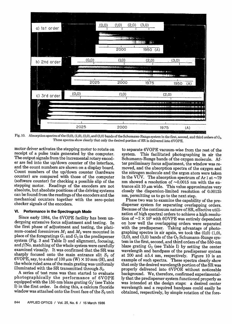
Fig. 10. Absorption spectra of the (0,0), (1,0), (2,0), and (3,0) bands of the Schumann-Runge system in the first, second, and third orders of G3These spectra show clearly that only the desired portion of SR is delivered into 6VOPE.
motor driver activates the stepping motor to rotate onreceipt of a pulse train generated by the computer.The output signals from the incremental rotary encod-er are fed into the up/down counter of the interface,and the count numbers are shown on a display board.Count numbers of the up/down counter (hardwarecounter) are compared with those of the computer(software counter) for checking a possible slip of thestepping motor. Readings of the encoders are notabsolute, but absolute positions of the driving systemscan be found from the readings of the encoders and themechanical counters together with the zero-pointchecker signals of the encoders.
VI. Performance in the Spectrograph Mode
Since early 1984, the 6VOPE facility has been un-dergoing extensive focus adjustment and testing. Inthe first phase of adjustment and testing, the plati-num-coated foremirrors M and M2 were mounted inplace of the foregratings G and G2 in the predispersersystem (Fig. 3 and Table I) and alignment, focusing,and f/No. matching of the whole system were carefullyexamined visually. It was confirmed that the SR wassharply focused onto the main entrance slit S2 of6VOPE, say, to a size of 100 gm (W) X 10 mm (H), andthe whole ruled area of the main grating was uniformlyilluminated with the SR transmitted through S2.
A series of test runs was then started to evaluatephotographically the performance of 6VOPEequipped with the 150-nm blaze grating G3' (see TableI) in the first order. In doing this, a calcium fluoridewindow was attached onto the front face of the 2 unit
to separate 6VOPE vacuum-wise from the rest of thesystem. This facilitated photographing in air theSchumann-Runge bands of the oxygen molecule. Af-ter preliminary focus adjustment, the window was re-moved, and the absorption spectra of the oxygen andthe nitrogen molecule and the argon atom were takenin the VUV. The absorption spectrum of Ar I at -79nm showed a resolution of -0.0015 nm with the en-trance slit 10,gm wide. This value approximates veryclosely the dispersion-limited resolution- of 0.00125nm, permitting us to go to the next step.
Phase two was to examine the capability of the pre-disperser system for separating overlapping orders.Because of the continuum nature of SR, effective utili-zation of high spectral orders to achieve a high resolu-tion of 2 X 10⁵ with 60VPE was entirely dependenton how well the overlapping orders were separatedwith the predisperser. Taking advantage of photo-graphing spectra in air again, we took the (0,0) (1,0),(2,0), and (3,0) bands of the 02 Schumann-Runge sys-tem in the first, second, and third orders of the 550-nmblaze grating G3 (see Table I) by setting the centerwavelength and bandpass of the predisperser systemat 200 and 5.4 nm, respectively. Figure 10 is anexample of such spectra. These spectra clearly showthat only the desired wavelength portion of the SR wasproperly delivered into 6VPOE without noticeablebackground. We, therefore, confirmed experimental-ly that the predisperser system functioned properly aswas intended at the design stage: a desired centerwavelength and a required bandpass could easily beobtained, respectively, by simple rotation of the fore-
}. as tVoilzok!iosti~> #u2ist~-u si e n§k#ah;+x ..... -. ES .
l l l l l l l l l l
789 790 (A)
nd(1/2) 1
nd(3/ 2)'
ns(3/2)
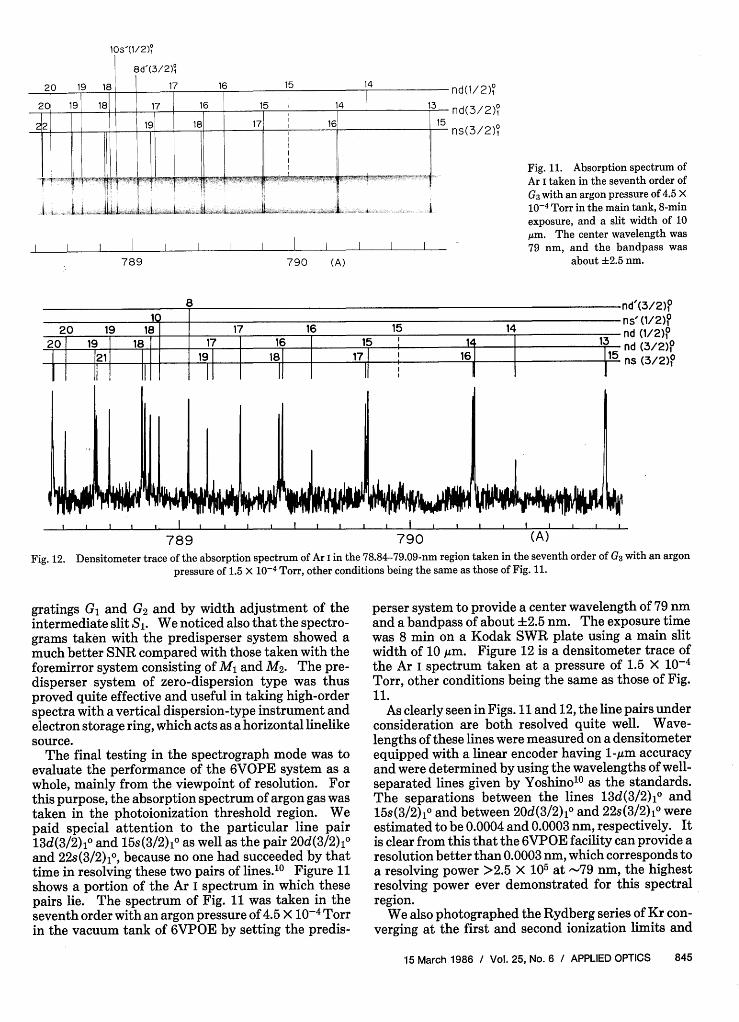
Fig. 11. Absorption spectrum ofAr I taken in the seventh order ofG3 with an argon pressure of 4.5 X
10-4 Torr in the main tank, 8-minexposure, and a slit width of 10kim. The center wavelength was79 nm, and the bandpass was
about +2.5 nm.
r U
IC.I ~~~~~~~~~~~~~~~~~~~~~ns20 19 18 17 16 15 14 nt
20 19 18 1_ 7 16 15 I1 I 13
__ ____ ___21 1 _ 18 17 i 16 115
I ,, I I , ,, I I I '
789 790 (A)
"(3/2)os(1/2)°d (1/2)o1 (3/2)os (3/2)o
Fig. 12. Densitometer trace of the absorption spectrum of Ar I in the 78.84-79.09-nm region taken in the seventh order of G3 with an argonpressure of 1.5 X 10⁻⁴ Torr, other conditions being the same as those of Fig. 11.
gratings G, and G2 and by width adjustment of theintermediate slit S1. We noticed also that the spectro-grams taken with the predisperser system showed amuch better SNR compared with those taken with theforemirror system consisting of Ml and M2. The pre-disperser system of zero-dispersion type was thusproved quite effective and useful in taking high-orderspectra with a vertical dispersion-type instrument andelectron storage ring, which acts as a horizontal linelikesource.
The final testing in the spectrograph mode was toevaluate the performance of the 6VOPE system as awhole, mainly from the viewpoint of resolution. Forthis purpose, the absorption spectrum of argon gas wastaken in the photoionization threshold region. Wepaid special attention to the particular line pair13d(3/2),o and 15s(3/2)10 as well as the pair 20d(3/2)10and 22s(3/2)io, because no one had succeeded by thattime in resolving these two pairs of lines.' 0 Figure 11shows a portion of the Ar I spectrum in which thesepairs lie. The spectrum of Fig. 11 was taken in theseventh order with an argon pressure of 4.5 X 10⁻⁴ Torrin the vacuum tank of 6VPOE by setting the predis-
perser system to provide a center wavelength of 79 niand a bandpass of about 2.5 nm. The exposure timewas 8 min on a Kodak SWR plate using a main slitwidth of 10 gim. Figure 12 is a densitometer trace ofthe Ar I spectrum taken at a pressure of 1.5 X 10⁻⁴
Torr, other conditions being the same as those of Fig.11.
As clearly seen in Figs. 11 and 12, the line pairs underconsideration are both resolved quite well. Wave-lengths of these lines were measured on a densitometerequipped with a linear encoder having 1-gum accuracyand were determined by using the wavelengths of well-separated lines given by Yoshinolo as the standards.The separations between the lines 13d(3/2)10 and15s(3/2)10 and between 20d(3/2) 10 and 22s(3/2)10 wereestimated to be 0.0004 and 0.0003 nm, respectively. Itis clear from this that the 6VPOE facility can provide aresolution better than 0.0003 nm, which corresponds toa resolving power >2.5 X 10⁵ at -79 nm, the highestresolving power ever demonstrated for this spectralregion.
We also photographed the Rydberg series of Kr con-verging at the first and second ionization limits and
5S1FR~~~~~i I ,;r T1- 1-anc, va \+E Al is.. .. $Aby - - I
EL a li ii ilid hJll i l it 11 i t. I w 11Clu. I 4t1i.E . ii i iji I i
I I I I I I I I I I ll
575 576 (A)
observed the members up to n = 69 both for thend(3/2)io and nd'(3/2)10 series. In the case of Ar, weobserved the nd(3/2)10 series up to n = 73. Thesenumbers favorably compare with n = 58 for Ar and n =60 for Kr, both of which were observed by Yoshino. 10 "'1
Figure 13 is a portion of the absorption spectrum ofNe taken in the tenth order, showing the Rydbergseries that converges at the first ionization limit. Itrequired a 40-min exposure time to take this spectrumwith a slit width of 10 m and at a neon pressure of 8 X10⁻⁴ Torr in the spectrograph. Five Rydberg serieswere observed: three series converging at the 2P 3/2limit and two at the 2P1 /2 limit, in accordance with theselection rules, for dipole transition. In the spectrumof Fig. 13, nd(1/2)1o lines are too weak to be seenbecause of their small absorption cross sections.
Recently, Baig and Connerade12 photographed theabsorption spectrum of neon in the 50-70-nm wave-length range using SR and a 3-m off-plane Eagle spec-trograph equipped with high-groove density holo-graphic gratings. In the spectrum taken in the secondorder of a 6000-groove/mm grating with a 10-gm slit,they observed the members of the nd(3/2)10 series upto n = 44. With the 6VOPE facility, the lines58d(3/2)1o and 59d(3/2)1o are well resolved in the tenthorder, as could be seen in Fig. 13.
We calibrated the absorption lines in wavelengthusing some intrnal standards of neon 3 and severalisolated lines measured by Baig and Connerade.12
Our wavelengths thus determined were in good agree-ment with those of Baig and Connerade except for veryclosely lying lines, particularly for the lines 26s(3/2)10and 12s'(3/2)io and for the lines 29d(3/2)1 0 andlld'(3/2) 1 0. The separations of the former pair andthe latter were found to be 0.0006 and 0.0007 nm,respectively. On the other hand, Baig and Conneradegive 0.0003 and 0.0002 nm for these two pairs. Thisdiscrepancy of 0.0003 nm, which corresponds to 24gmon our plate, is too large to be ascribed to errors in ourmeasurement of the line positions relative to one an-other. (Note that we are not dealing with absolutewavelengths but relative wavelengths.)
It should be mentioned in passing in connection withour observation on the neon spectrum that the amountof absorption between the two closely lying linesns'(1/2)1o and (n - )d'(3/2)10 with n 14 is larger thanthe background absorption level which corresponds to
ns'(1/2)0
nd'(3/2)?
nd (3/2)0
ns (3/2)0
Fig. 13. Absorption spectrum ofNe I taken in the tenth order of G3with a center wavelength of 58 nm,a bandpass of about 2 nm, aneon pressure of 8.0 X 10⁻⁴ Torr,40-min exposure, and a slit width
of 10 am.
the continuum due to direct ionization to Ne II2P3/2.Recent theoretical treatment by Johnson and LeDourneuf' 4 does not show this feature. Although weare well aware of the fact that photographic detectionis notorious in the determination of intensities, wethink, on the grounds of the high resolution weachieved, this discrepancy could be real (note that ourinstrumental width is definitely 1 order of magnitudesmaller than that of Radler and Berkowitz 5). Toclarify the situation, it is essential to measure the lineprofiles by means of photoelectric detection. In thissense, the 6VOPE facility will provide a realistic meansto approaching this end when its focal plane scanningmode becomes operational.
Vil. Conclusion
We have designed and constructed the 6VOPE facil-ity at the Photon Factory. The predisperser system ofzero-dispersion type was designed to have the capabili-ty of sp arating the overlapping orders by simple rota-tion dithe two foregratings and adjustment of thewidth of the intermediate slit and was proved quiteeffective and useful for taking high-order spectra witha vertical dispersion-type instrument and SR. Fur-thermore, the resolving power of the 6VOPE facilitywas estimated from the separation of two closely lyinglines in the absorption spectrum of Ar I in the seventhorder to be >2.5 X 10⁵ -the highest resolving powerever reported in this spectral region.
The authors wish to thank K. Ueda, A. Takahashi,T. Akahori, and the staff of the Photon Factory forinvaluable contributions to the 6VOPE project. Theauthors also wish to express their gratitude to Shi-madzu Corp. for dedication and expert workmanshipin the construction of 6VOPE and to T. Harada and T.Kita for ruling the foregratings in the predispersersystem. The authors are indebted to M. Seya, S.Oshio, S. Minami, and H. Kuroda for their interest inthis work.
References
1. T. Namioka, "Theory of the Concave Grating. II. Applicationof the Theory to the Off-Plane Eagle Mounting in a VacuumSpectrograph," J. Opt. Soc. Am. 49, 460 (1959).
2. T. Namioka, "Design of High-Resolution Monochromator forthe Vacuum Ultraviolet. An Application of Off-Plane EagleMounting," J. Opt. Soc. Am. 49, 961 (1959).
3. P. G. Wilkinson, "A High Resolution Spectrograph for the Vacu-um Ultraviolet," J. Mol. Spectrosc. 1, 288 (1957).
4. M. L. Ginter, D. S. Ginter, and C. M. Brown, "Need for HighResolution in VUV Rydberg State Spectroscopy," Appl. Opt. 19,4015 (1980).
5. T. Namioka, H. Noda, K. Goto, and T. Katayama, "Design
Studies of Mirror-Grating Systems for Use with an ElectronStorage Ring Source at the Photon Factory," Nucl. Instrum.Methods 208, 215 (1983).
6. H. E. Blackwell, G. S. Shipp, M. Ogawa, and G. L. Weissler,"Properties of a Plane Grating Predisperser Used with a GrazingIncidence Vacuum Spectrograph," J. Opt. Soc. Am. 56, 665(1966).
7. A. E. Douglas and G. Herzberg, "Separation of OverlappingOrders of a Concave Grating Spectrograph in the Vacuum Ultra-violet Region," J. Opt. Soc. Am. 47, 625 (1957).
8. M. L. Ginter, "New High Resolution [>1.5 X 10⁵] VUV Spectro-scopic Facilities in Japan and the United States," to be pub-lished in Nucl. Instrum. Methods (1986).
Patter continued from page 817
The Fabry-Perot etalons are adjusted to select the oscillation frequency andto provide a single, high-contrast interference-fringe pattern. The pulseduration and cavity length permit about 15 double passes (round trips) of thelight beam through the laser cavity, resulting in a bandwidth of no more than 7X 10⁻⁴ A, as measured by the width and separation of the fringes. The outputpulse duration at this linewidth is about 60 ns and the pulse energy between 5and 10 pJ. The measured beam divergence is 0.2 mrad, which is at thediffraction limit.
This work was done by Thomas J. Pacala, lain Stuart McDermid, and JamesB. Laudenslager of Caltech for NASA's Jet Propulsion Laboratory. Refer toNPO-16410.
Improved waveguide laser arrayAn improved structure for an integrated array of AlGal-_As diode lasers
causes the array to oscillate predominantly in the fundamental supermode(with all units at the same phase), thereby producing an intense, narrow lightbeam. The new structure differs from the older ones in that the gain in thespaces between the laser channels is approximately equal to the gain in thechannels.
In the new structure, the laser/waveguide channels are distinguished fromthe interchannel spaces in refractive index but not in gain. The refractiveindex of each channel is slightly higher than the index of the surroundingstructure. This partially confines the light to the channels. In earlier ver-sions, the spaces between the channels were absorptive. This favored oscilla-tion in supermodes that were least absorbed in the interchannel spaces, that is,in the high-order supermodes. In the new structure, there is no longer amechanism that favors the high-order supermodes, and the fundamentalsupermode can dominate.
Wafers with the improved laser arrays were prepared by liquid-phase epi-taxial growth. First, the layers up to and including the p-Alo.iGao.9 As layercontaining the laser channels (see Fig. 4) were grown on an n+-GaAs substrate.The spaces between the channels were than formed by etching with a 1:8:8mixture of H2 504, H202, and H20. The remaining laser ridges were then 0.5jAm high. Two lateral ridge (channel) spacings were used: ridges 4.5 Mm widewith a 9-Mm period and ridges 2.5 ,m wide with a 5-Mm period.
The ridges were covered with a 4-Am thick layer of Ge-doped p-AIO.4Gao.6As.The ridges thus became buried laser/waveguide channels. The next layer was
Fig. 4. Laser array is formed of layers and channels of AlxGal-,Asdeposited epitaxially. In this structure, the layer, channel, andinterchannel dopings are chosen so that the gain in the interchannel
spaces is the same as the gain in the channels.
9. T. Koide et al., "Mirror System for a VUV Beam Line at thePhoton Factory," to be published in Nucl. Instrum. MethodsA239, 350 (1986).
10. K. Yoshino, "Absorption Spectrum of the Argon Atom in theVacuum-Ultraviolet Region," J. Opt. Soc. Am. 60, 1220 (1970).
11. K. Yoshino and Y. Tanaka, "Absorption Spectrum of Kryptonin the Vacuum UV Region," J. Opt. Soc. Am. 69,159 (1979).
12. M. A. Baig and J. P. Connerade, "Centrifugal Barrier Effects inthe Rydberg States and Autoionising Resonances of Neon," J.Phys. B. 17,1785 (1984).
13. V. Kaufman and B. Edl6n, "Reference Wavelength from AtomicSpectra in the Range 15 A to 25000 A," J. Phys. Chem. Ref. Data3, 825 (1974).
14. E. R. Johnson and M. Le Dourneuf, "Analysis of the Autoionis-ing Resonances in Neon near 575 A," J. Phys. B 13, L13 (1980).
15. K. Radler and J. Berkowitz, "Photoionization Mass Spectrome-try of Neon Using Synchrotron Radiation: Anomalous Varia-tion of Resonance Widths in the Noble Gases," J. Chem. Phys.70, 216 (1979).
9-jan Spacing
A- \ Wr
10 5 0 5 10
Angle (Degrees)
0
0en
I
-c
a:
20 10 0 10 20
Angle (Degrees)
Fig. 5. These far-field radiation patterns show the performances oflaser array like the one in Fig. 4. These measurements are per-formed in the plane of the laser junctions. The angles are measuredwith respect to the forward direction (the direction along the chan-