International Journal of Mechanical Engineering and Technology (IJMET) Volume 9, Issue 13, December 2018, pp. 452–463, Article ID: IJMET_09_13_047 Available online at http://www.iaeme.com/ijmet/issues.asp?JType=IJMET&VType=9&IType=13 ISSN Print: 0976-6340 and ISSN Online: 0976-6359
HIGH REYNOLDS NUMBER SOLUTIONS OF STEADY INCOMPRESSIBLE 2-D FLOW
AROUND A SQUARE CYLINDER CONFINED IN A CHANNEL WITH 1/8 BLOCKAGE RATIO
Ercan Erturk Bahcesehir University, Mechatronics Engineering Department
Besiktas, Istanbul, Turkey
Orhan Gokcol Bahcesehir University, Computer Education and Instructional Technologies Department
Besiktas, Istanbul, Turkey
ABSTRACT Steady incompressible viscous flow past a square cylinder confined in a channel is
numerically simulated. The considered channel has a blockage ratio of 1/8. The governing 2-D steady incompressible Navier–Stokes equations are solved with a very efficient finite difference numerical method using a very large stretched mesh such that the inflow and the outflow boundary is located very far away from the square cylinder. The numerical solutions of steady incompressible viscous flow around a square cylinder confined in a channel with 1/8 blockage ratio is obtained up to Reynolds number of 410. Detailed results of the flow characteristics are presented.
Key words: Flow around confined square cylinder, high Reynolds numbers
Cite this Article: Ercan Erturk and Orhan Gokcol, High Reynolds Number Solutions of Steady Incompressible 2-D Flow Around a Square Cylinder Confined in a Channel with 1/8 Blockage Ratio, International Journal of Mechanical Engineering and Technology, 9(13), 2018, pp. 452–463. http://www.iaeme.com/IJMET/issues.asp?JType=IJMET&VType=9&IType=13
1. INTRODUCTION The flow over bluff bodies is studied extensively in computational fluid dynamics field of study. The flow past a square cylinder is encountered in many engineering applications such as the heat exchangers. In the literature it is possible to find many studies about the subject of the flow around a square cylinder [1-9]. For example, Sen, Mittal and Biswas [1] studied the flow past a square cylinder at low Reynolds numbers. The flow they [1] considered was an external flow such that the square cylinder was not confined in a channel. Kumar and Ray [2] also studied the external flow around a square cylinder. They [2] considered that the inlet velocity
High Reynolds Number Solutions of Steady Incompressible 2-D Flow around a Square Cylinder Confined in a Channel with 1/8 Blockage Ratio
profile had a linear shear. In the literature, Dhiman, Chhabra and Eswaran [3] investigated the effect of the Peclet number on the internal flow across a square cylinder confined in a channel. Sahu, Chhabra and Eswaran [4] studied the flow of a power law fluid across a confined cylinder. Dhiman, Chhabra and Eswaran [5] studied the effect of the blockage ratio as well as the effect of the power-law on the steady flow across a confined square cylinder. Dhiman, Sharma and Kumar [6] investigated the effects of blockage ratio on the combined free and forced convection from a long heated square obstacle confined in a horizontal channel. In the literature also Tezel, Yapici and Uludag [7], Kumar, Dass and Dewan [8] and Breuer, Bernsdorf, Zeiser and Durst [9] presented numerical simulation of the steady incompressible 2-D flow over a square cylinder confined in a channel. However, the steady solutions presented in Tezel, Yapici and Uludag [7], Kumar, Dass and Dewan [8] and Breuer, Bernsdorf, Zeiser and Durst [9] are for very low Reynolds numbers. To the best of our knowledge, in the literature there are no studies that considers the numerical solutions of the 2-D steady incompressible flow past a square cylinder confined in a channel at high Reynolds numbers. High Reynolds number behavior of the confined channel flow over a square cylinder has never been studied.
The aim of this study is then to numerically simulate the 2-D steady incompressible flow around a square cylinder confined in a channel at high Reynolds numbers. In this study, the efficient numerical method that allows numerical solutions at high Reynolds numbers described in Erturk, Corke and Gökçöl [10], Erturk, Haddad and Corke [11] and Erturk [12] is applied to solve to the governing Navier-Stokes equations. With this, the steady flow around a square cylinder confined in a channel is solved up to high Reynolds number of =410 using a very large mesh. Detailed quantitative numerical results are presented for future references.
2. PROBLEM FORMULATION AND NUMERICAL METHOD For the numerical solution of the steady incompressible 2-D flow around a square cylinder confined in a channel, we use the streamfunction ( ) and vorticity ( ) formulation of the Navier-Stokes equations. These equations are given as the following
(1)
(2)
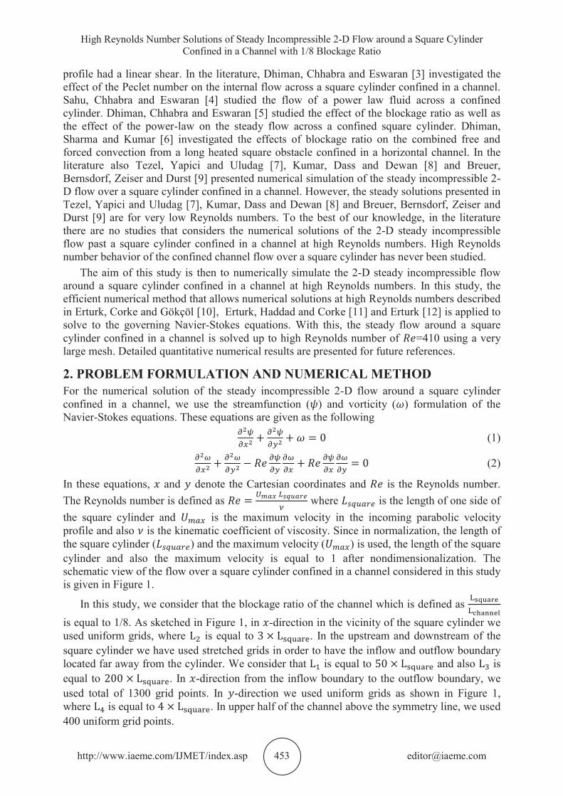
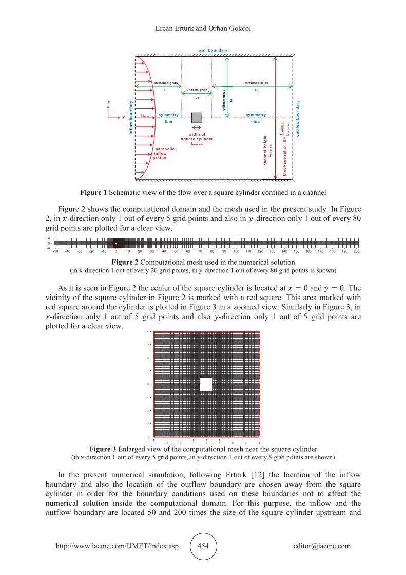
In these equations, and denote the Cartesian coordinates and is the Reynolds number. The Reynolds number is defined as where is the length of one side of the square cylinder and is the maximum velocity in the incoming parabolic velocity profile and also is the kinematic coefficient of viscosity. Since in normalization, the length of the square cylinder ( ) and the maximum velocity ( ) is used, the length of the square cylinder and also the maximum velocity is equal to 1 after nondimensionalization. The schematic view of the flow over a square cylinder confined in a channel considered in this study is given in Figure 1.
In this study, we consider that the blockage ratio of the channel which is defined as is equal to 1/8. As sketched in Figure 1, in -direction in the vicinity of the square cylinder we used uniform grids, where is equal to . In the upstream and downstream of the square cylinder we have used stretched grids in order to have the inflow and outflow boundary located far away from the cylinder. We consider that is equal to and also is equal to . In -direction from the inflow boundary to the outflow boundary, we used total of 1300 grid points. In -direction we used uniform grids as shown in Figure 1, where is equal to . In upper half of the channel above the symmetry line, we used 400 uniform grid points.
Figure 1 Schematic view of the flow over a square cylinder confined in a channel
Figure 2 shows the computational domain and the mesh used in the present study. In Figure 2, in -direction only 1 out of every 5 grid points and also in -direction only 1 out of every 80 grid points are plotted for a clear view.
Figure 2 Computational mesh used in the numerical solution
(in x-direction 1 out of every 20 grid points, in y-direction 1 out of every 80 grid points is shown)
As it is seen in Figure 2 the center of the square cylinder is located at and . The vicinity of the square cylinder in Figure 2 is marked with a red square. This area marked with red square around the cylinder is plotted in Figure 3 in a zoomed view. Similarly in Figure 3, in
-direction only 1 out of 5 grid points and also -direction only 1 out of 5 grid points are plotted for a clear view.
Figure 3 Enlarged view of the computational mesh near the square cylinder
(in x-direction 1 out of every 5 grid points, in y-direction 1 out of every 5 grid points are shown)
In the present numerical simulation, following Erturk [12] the location of the inflow boundary and also the location of the outflow boundary are chosen away from the square cylinder in order for the boundary conditions used on these boundaries not to affect the numerical solution inside the computational domain. For this purpose, the inflow and the outflow boundary are located 50 and 200 times the size of the square cylinder upstream and
uniform grids
L2
symmetry
line
symmetry
line
infl
ow b
ound
ary
outf
low
bou
ndar
y
wall boundary
stretched grids
L1
stretched grids
L3
unifo
rmgr
ids
L4y
x
parabolicinflow
profile
width ofsquare cylinder
Lsqu are
chan
nel h
eigh
tL
chan
nel
bloc
kage
rat
io
B=
L sq
uar
e
Lch
an
ne
l
Um a x
High Reynolds Number Solutions of Steady Incompressible 2-D Flow around a Square Cylinder Confined in a Channel with 1/8 Blockage Ratio
downstream of the cylinder respectively. Therefore, the total length of the channel is equal to 250 times the size of the square cylinder. Such a long channel ensures that the location of the inflow and outflow boundaries do not have any influence on the interior numerical solution.
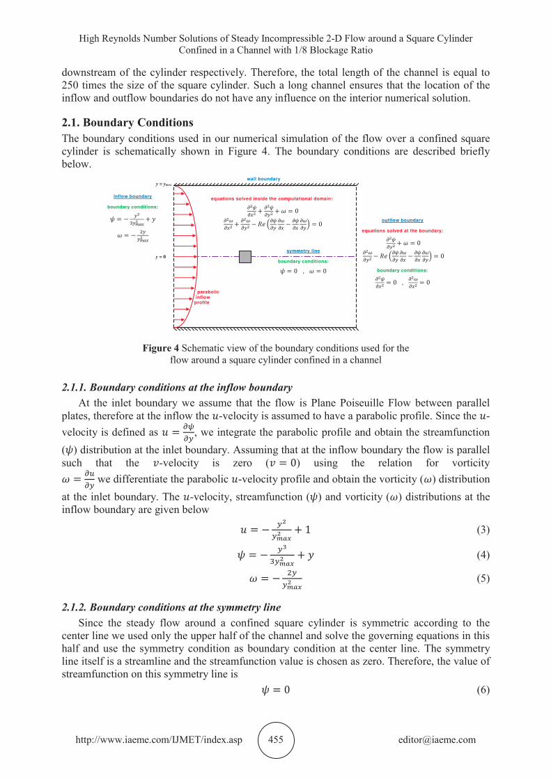
2.1. Boundary Conditions The boundary conditions used in our numerical simulation of the flow over a confined square cylinder is schematically shown in Figure 4. The boundary conditions are described briefly below.
Figure 4 Schematic view of the boundary conditions used for the flow around a square cylinder confined in a channel
2.1.1. Boundary conditions at the inflow boundary At the inlet boundary we assume that the flow is Plane Poiseuille Flow between parallel
plates, therefore at the inflow the -velocity is assumed to have a parabolic profile. Since the -velocity is defined as , we integrate the parabolic profile and obtain the streamfunction ( ) distribution at the inlet boundary. Assuming that at the inflow boundary the flow is parallel such that the -velocity is zero ( ) using the relation for vorticity
we differentiate the parabolic -velocity profile and obtain the vorticity ( ) distribution at the inlet boundary. The -velocity, streamfunction ( ) and vorticity ( ) distributions at the inflow boundary are given below
(3)
(4)
(5)
2.1.2. Boundary conditions at the symmetry line Since the steady flow around a confined square cylinder is symmetric according to the
center line we used only the upper half of the channel and solve the governing equations in this half and use the symmetry condition as boundary condition at the center line. The symmetry line itself is a streamline and the streamfunction value is chosen as zero. Therefore, the value of streamfunction on this symmetry line is (6)
As the same with the streamfunction variable, at the symmetry line the vorticity value is also zero. (7)
2.1.3. Boundary conditions at the outflow boundary At the outflow boundary we used a non-reflecting boundary condition such that any wave
generated in the computational domain could pass through the exit boundary and leave without any reflection back into the computational domain. For details on non-reflecting boundary conditions the reader is referred to the study of Engquist and Majda [13] in which the nonreflecting boundary condition concept is first introduced in the name of “Absorbing Boundary Condition”, and also to Jin and Braza [14] for a review of non-reflecting boundary conditions. Liu and Lin [15] used a buffer region in the physical domain to damp erroneous numerical fluctuations near the outflow boundary. In this region they [15] added a buffer function to the second order streamwise derivatives in the momentum equations such that the reflected outgoing waves from an artificially truncated outlet are thus absorbed. This approach for the exit boundary condition has been used in various similar studies [11,12] successfully. Therefore, at the outflow boundary we solve the streamfunction and vorticity equations (1) and (2) without the elliptic terms, i.e. , such as
(8)
(9)
We note that the discretization of equation (9) requires a ghost grid point outside the computational domain. The value of this ghost grid point is calculated using the fact that on this outflow boundary and such that and change linearly.
In the computational domain near the outflow boundary, in order to have smooth transition from the streamfunction and vorticity equations (1) and (2) used inside the solution domain to the streamfunction and vorticity equations without the elliptic terms (8) and (9) used at the outflow boundary, we used a buffer zone as it was done in [11,12]. In this buffer zone we kill the elliptic terms in the governing equations gradually. To accomplish this, these elliptic terms are multiplied by a weighting factor . At the beginning of the buffer zone, we set =1 and at the end of the buffer zone, it is zero, = 0. In between, the weighting factor changes as
(10)
where
(11)
where is the numerical streamwise index, is the numerical index of the last grid point in streamwise direction and is the index of the first grid point at the beginning of the buffer zone. We used 20 grid points in this buffer zone. Therefore, near the outflow boundary in the computational domain, in this buffer zone we basically solve the following equations
(12)
(13)
High Reynolds Number Solutions of Steady Incompressible 2-D Flow around a Square Cylinder Confined in a Channel with 1/8 Blockage Ratio
where is defined in equation (10). The non-reflecting boundary condition together with a buffer zone provides very smooth solutions. This approach increases the accuracy of the numerical solution used inside the computational domain.
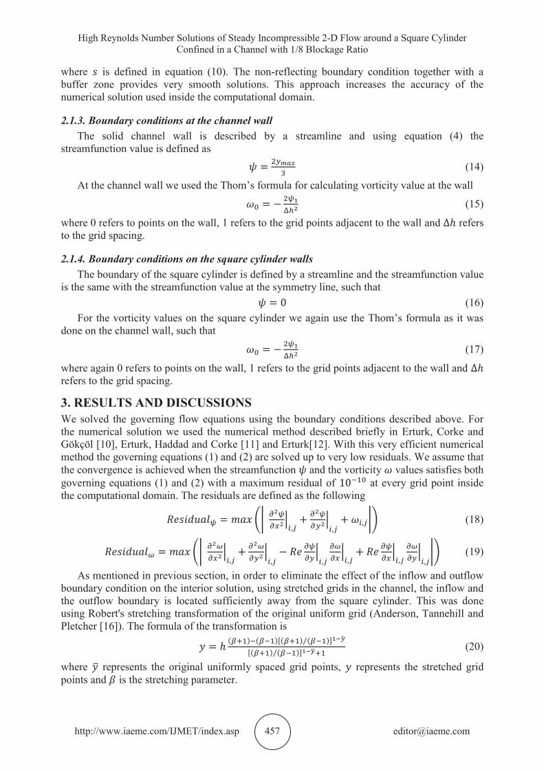
2.1.3. Boundary conditions at the channel wall The solid channel wall is described by a streamline and using equation (4) the
streamfunction value is defined as
(14)
At the channel wall we used the Thom’s formula for calculating vorticity value at the wall
(15)
where 0 refers to points on the wall, 1 refers to the grid points adjacent to the wall and refers to the grid spacing.
2.1.4. Boundary conditions on the square cylinder walls The boundary of the square cylinder is defined by a streamline and the streamfunction value
is the same with the streamfunction value at the symmetry line, such that (16)
For the vorticity values on the square cylinder we again use the Thom’s formula as it was done on the channel wall, such that
(17)
where again 0 refers to points on the wall, 1 refers to the grid points adjacent to the wall and refers to the grid spacing.
3. RESULTS AND DISCUSSIONS We solved the governing flow equations using the boundary conditions described above. For the numerical solution we used the numerical method described briefly in Erturk, Corke and Gökçöl [10], Erturk, Haddad and Corke [11] and Erturk[12]. With this very efficient numerical method the governing equations (1) and (2) are solved up to very low residuals. We assume that the convergence is achieved when the streamfunction and the vorticity values satisfies both governing equations (1) and (2) with a maximum residual of at every grid point inside the computational domain. The residuals are defined as the following
(18)
(19)
As mentioned in previous section, in order to eliminate the effect of the inflow and outflow boundary condition on the interior solution, using stretched grids in the channel, the inflow and the outflow boundary is located sufficiently away from the square cylinder. This was done using Robert's stretching transformation of the original uniform grid (Anderson, Tannehill and Pletcher [16]). The formula of the transformation is
(20)
where represents the original uniformly spaced grid points, represents the stretched grid points and is the stretching parameter.
We believe that with the use of large number of grid points and with having the inflow and the outflow boundary sufficiently away from the square cylinder using a stretching function and also the very low residuals used for convergence criteria our numerical solutions are indeed very accurate.
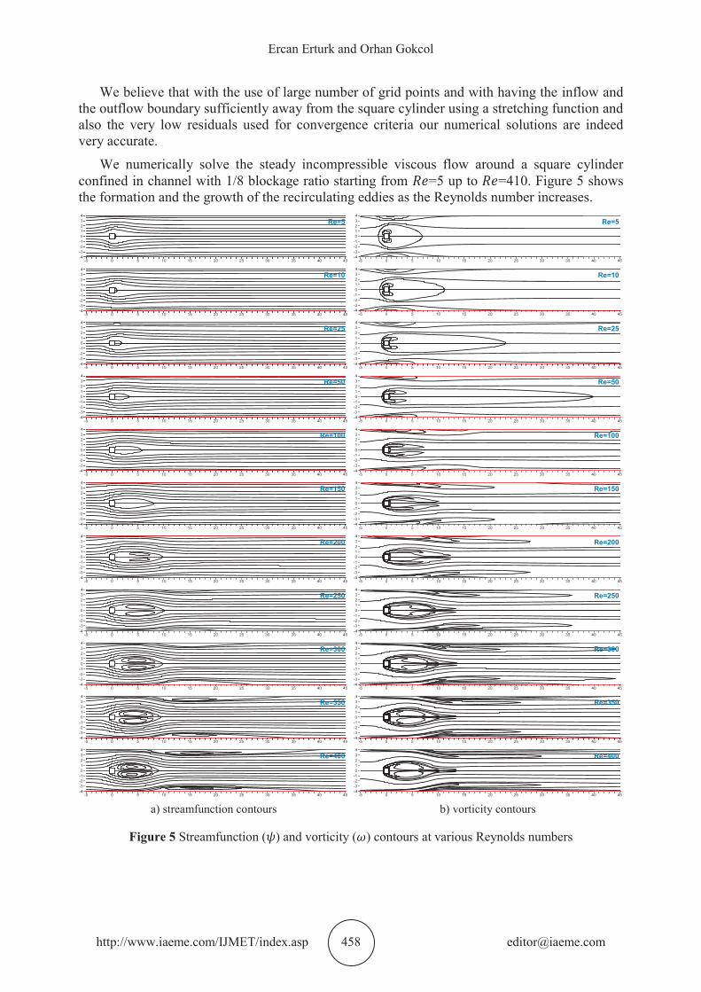
We numerically solve the steady incompressible viscous flow around a square cylinder confined in channel with 1/8 blockage ratio starting from =5 up to =410. Figure 5 shows the formation and the growth of the recirculating eddies as the Reynolds number increases.
Re=5 -
Re=5 -
Re=10 -
Re=10 -
Re=25 -
Re=25 -
Re=50 -
Re=50 -
Re=100 -
Re=100 -
Re=150 -
Re=150 -
Re=200 -
Re=200 -
Re=250 -
Re=250 -
Re=300 -
Re=300 -
Re=350 -
Re=350 -
Re=400 -
Re=400 -
a) streamfunction contours b) vorticity contours
Figure 5 Streamfunction ( ) and vorticity ( ) contours at various Reynolds numbers
High Reynolds Number Solutions of Steady Incompressible 2-D Flow around a Square Cylinder Confined in a Channel with 1/8 Blockage Ratio
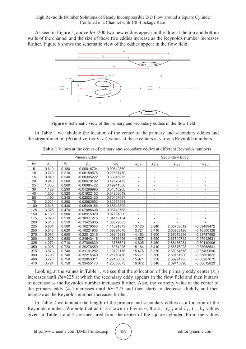
As seen in Figure 5, above =200 two new eddies appear in the flow at the top and bottom walls of the channel and the size of these two eddies increase as the Reynolds number increases further. Figure 6 shows the schematic view of the eddies appear in the flow field.
Figure 6 Schematic view of the primary and secondary eddies in the flow field
In Table 1 we tabulate the location of the center of the primary and secondary eddies and the streamfunction ( ) and vorticity ( ) values at these centers at various Reynolds numbers.
Table 1 Values at the center of primary and secondary eddies at different Reynolds numbers
Looking at the values in Table 1, we see that the -location of the primary eddy center ( ) increases until =225 at which the secondary eddy appears in the flow field and then it starts to decrease as the Reynolds number increases further. Also, the vorticity value at the center of the primary eddy ( ) increases until =225 and then starts to decrease slightly and then increase as the Reynolds number increases further.
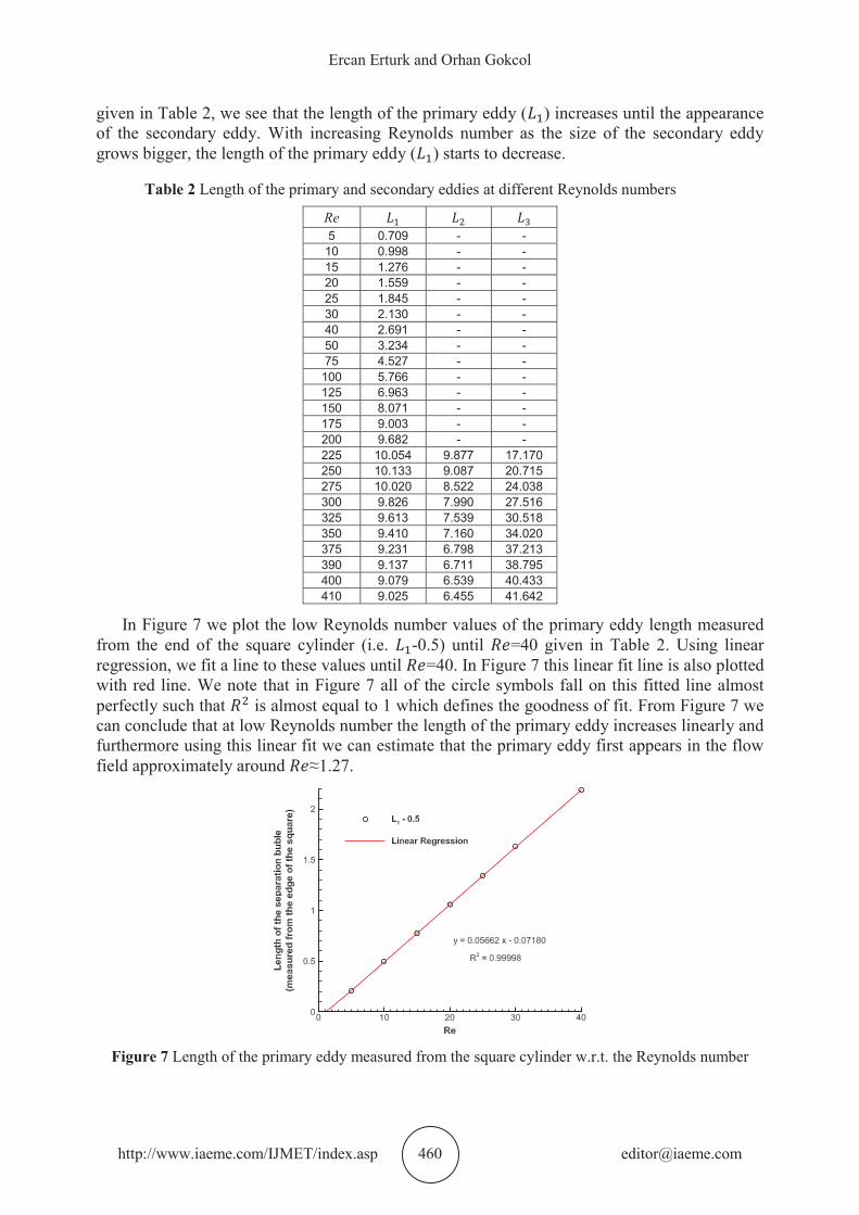
In Table 2 we tabulate the length of the primary and secondary eddies as a function of the Reynolds number. We note that as it is shown in Figure 6, the , and , , values given in Table 1 and 2 are measured from the center of the square cylinder. From the values
given in Table 2, we see that the length of the primary eddy ( ) increases until the appearance of the secondary eddy. With increasing Reynolds number as the size of the secondary eddy grows bigger, the length of the primary eddy ( ) starts to decrease.
In Figure 7 we plot the low Reynolds number values of the primary eddy length measured from the end of the square cylinder (i.e. -0.5) until =40 given in Table 2. Using linear regression, we fit a line to these values until =40. In Figure 7 this linear fit line is also plotted with red line. We note that in Figure 7 all of the circle symbols fall on this fitted line almost perfectly such that is almost equal to 1 which defines the goodness of fit. From Figure 7 we can conclude that at low Reynolds number the length of the primary eddy increases linearly and furthermore using this linear fit we can estimate that the primary eddy first appears in the flow field approximately around ≈1.27.
Figure 7 Length of the primary eddy measured from the square cylinder w.r.t. the Reynolds number
High Reynolds Number Solutions of Steady Incompressible 2-D Flow around a Square Cylinder Confined in a Channel with 1/8 Blockage Ratio
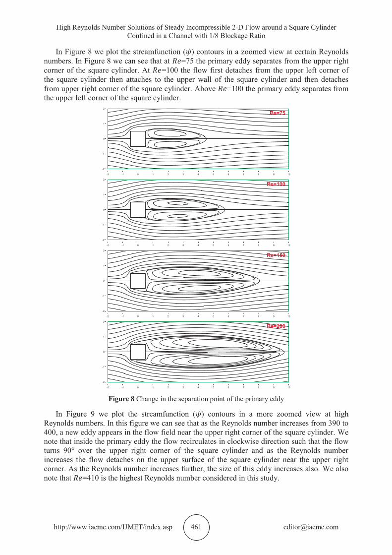
In Figure 8 we plot the streamfunction ( ) contours in a zoomed view at certain Reynolds numbers. In Figure 8 we can see that at =75 the primary eddy separates from the upper right corner of the square cylinder. At =100 the flow first detaches from the upper left corner of the square cylinder then attaches to the upper wall of the square cylinder and then detaches from upper right corner of the square cylinder. Above =100 the primary eddy separates from the upper left corner of the square cylinder.
Re=75 -
Re=100 -
Re=150 -
Re=200 -
Figure 8 Change in the separation point of the primary eddy
In Figure 9 we plot the streamfunction ( ) contours in a more zoomed view at high Reynolds numbers. In this figure we can see that as the Reynolds number increases from 390 to 400, a new eddy appears in the flow field near the upper right corner of the square cylinder. We note that inside the primary eddy the flow recirculates in clockwise direction such that the flow turns 90° over the upper right corner of the square cylinder and as the Reynolds number increases the flow detaches on the upper surface of the square cylinder near the upper right corner. As the Reynolds number increases further, the size of this eddy increases also. We also note that =410 is the highest Reynolds number considered in this study.
Figure 9 Appearance and growth of a new eddy on the upper right corner of the square cylinder
4. CONCLUSIONS In this study the numerical solutions of steady incompressible viscous flow around a square cylinder confined in a channel are presented. With using a very efficient numerical method together with a large number of grid points, highly accurate numerical solutions are obtained at very high Reynolds numbers with very low residuals. Our results indicate the appearance of secondary eddies between =200 and =225 at the top and bottom walls of the channel. Also around =400 a new eddie appear on the upper surface of the square cylinder near the upper right corner.
REFERENCES [1] Sen S, Mittal S, Biswas G. “Flow Past a Square Cylinder at Low Reynolds Numbers”,
International Journal for Numerical Methods in Fluids 2011; 67:1160-1174 [2] Kumar A, Ray RK. “Numerical Study of Shear Flow Past a Square Cylinder at Reynolds
Numbers 100, 200”, Procedia Engineering 2015; 127:102-109 [3] Dhiman AK, Chhabra RP, Eswaran V. “Flow and Heat Transfer Across a Confined Square
Cylinder in the Steady Flow Regime: Effect of Peclet Number”, International Journal of Heat and Mass Transfer 2005; 48:4598-4614
High Reynolds Number Solutions of Steady Incompressible 2-D Flow around a Square Cylinder Confined in a Channel with 1/8 Blockage Ratio
[4] Sahu AK, Chhabra RP, Eswaran V. “Two-Dimensional Laminar Flow of a Power-Law Fluid Across a Confined Square Cylinder”, Journal of Non-Newtonian Fluid Mechanics 2010; 165:752-763
[5] Dhiman AK, Chhabra RP, Eswaran V. “Steady Flow Across a Confined Square Cylinder: Effects of Power-Law Index and Blockage Ratio”, Journal of Non-Newtonian Fluid Mechanics 2008; 148:141-150
[6] Dhiman AK, Sharma N, Kumar S. “Wall Effects on the Cross-Buoyancy Around a Square Cylinder in the Steady Regime”, Brazilian Journal of Chemical Engineering 2012; 29:253-264
[7] Tezel GB, Yapici K, Uludag Y. “Numerical and Experimental Investigation of Newtonian Flow Around a Confined Square Cylinder”, Periodica Polytechnica Chemical Engineering 2019; 63:190-199
[8] Kumar DS, Dass AK, Dewan A. “Numerical Simulation of Viscous Flow Over a Square Cylinder on Graded Cartesian Meshes Using Multigrid Method”, Proceedings of the 37th International & 4th National Conference on Fluid Mechanics and Fluid Power FMFP2010, December 16-18, 2010, IIT Madras, Chennai, India
[9] Breuer M, Bernsdorf J, Zeiser T, Durst F. “Accurate Computations of the Laminar Flow Past a Square Cylinder Based on Two Different Methods: Lattice-Boltzmann and Finite-Volume”, International Journal of Heat and Fluid Flow 2000; 21:186-196
[10] Erturk E, Corke TC, Gökçöl C. “Numerical solutions of 2-D steady incompressible driven cavity flow at high Reynolds numbers”. International Journal for Numerical Methods in Fluids 2005; 48:747-774
[11] Erturk E, Haddad OM, Corke TC. “Laminar Incompressible Flow Past Parabolic Bodies at Angles of Attack”. AIAA Journal 2004; 42:2254-2265
[12] Erturk E. “Numerical solutions of 2-D steady incompressible flow over a backward-facing step, Part I: High Reynolds number solutions”. Computers & Fluids 2008; 37:633-655
[13] Engquist B, Majda A. “Absorbing boundary conditions for the numerical simulation of waves”. Mathematics of Computation 1977;31:629-651.
[14] Jin G, Braza M. “A non-reflecting outlet boundary condition for incompressible unsteady Navier–Stokes calculations”. Journal of Computational Physics 1993;107:239-253
[15] Liu C, Lin Z. “High order finite difference and multigrid methods for spatially-evolving instability”. Journal of Computational Physics 1993;106:92–100.
[16] Anderson DA, Tannehill JC, Pletcher RH. “Computational Fluid Mechanics and Heat Transfer”. McGraw-Hill, 1984