Abstract—The development of new power electronic device
and high performance magnetic materials are the main
technological factors that have led both industries and research
community to focus their attention on high speed electrical
drives. Several papers have already outlined the electrical
machine and/or converter topology choice for certain high
speed application. This choice obviously depends on the
applications under study. This paper aims to identify the most
important high speed applications. For each of them, the main
design challenges are highlighted and an overview of the
already available product on the market is presented.
Keywords—high speed, electrical machine, high speed
applications, high speed drives,
I. INTRODUCTION
The developments of new power-electronic devices, power electronic converters, manufacturing methods and materials have opened up exciting avenues in electrical machines research. One such area, high-speed electrical machines have seen a rapid growth in the last few decades, with a considerable application uptake in the last decade. The design of high speed electrical machine is notoriously more challenging compared to classical ones, often requiring a multi-disciplinary design environment to account for the coupling between different physics aspect. The actual definition of what constitutes ‘high-speed’ and what is actually ‘challenging design’ has also long been debated in technical literature [1]-[2]. High speed machines are mainly classified according to the peripheral speed of the rotating element which translates in mechanical stresses. The main limitation in the rotational speed is therefore determined by the mechanical properties of currently available materials. However, the challenge in designing high speed electrical machine is probably best described by the ‘rpm√kW’ figure-of-merit introduced in [1]. The power electronics has moved towards switching modules with increased capabilities in term of switching frequencies as well as featuring a reduction in the losses. The growth rate of power electronic modules has been enhanced by the introduction of SiC and GaN devices. Thanks to the introduction of high switching frequency devices, mono-directional and regenerative power converter has been adopted to actively control high speed electrical machines aiming high performance drives. The emission regulations and the cost of energy has played an important role in the industrial environment which has become more interested in direct drive solution featuring high power to weight ratio further enhancing the reliability
and efficiency of the system. High speed drives has gained a growing interest in automotive, aerospace, power conversion and recovery, spindles, pump and compressors. High speed drives has become state of the art for some of the aforementioned application while in some niche application, the adopting of high speed drives has enhanced the performances and the capabilities in terms of product quality and product innovation.
TABLE I: POWER-SPEED NODES FOR SELECTED
APPLICATIONS
Application Power Speed
Oil & Gas 3MW to 15MW 5-15 krpm
Spindles 300W to 60kW 15-300 krpm
Turbocharger
(Pass-car/Truck) 1-3kW / 10kW 150krpm / 80krpm
Air Compressor 40kW to 500kW 15-80 krpm
Micro-turbines 30kW to 400kW, 15-120 krpm
Turbo-molecular pumps
50W to 3kW 70-100krpm
Different topologies have been adopted for what concerns the electrical machines. Considering the challenges in achieving high speed, the robustness of the rotating element is a critical factor in the selection of the machine. New materials, improved power electronic devices and the engineered integration process at the design stage are improving the capabilities of high speed drives in the industrial market [1]. In the following sections, the authors present a review on the today application of high speed technology and their role in the industrial environment. Table I summarize the key industrial application that are following detailed focusing in their power-speed node of operation. The machine topologies mainly adopted as well as the power electronics implemented are described focusing on their key aspects to achieve high operational speed.
II. OIL AND GAS APPLICATIONS
Gas compression is needed at many places in the chemical, oil and gas industry, mainly for gathering, transmission and processing the gas downstream. Gas engines and gas turbines are traditionally used as the compressor drives. While gas fired drives are convenient for
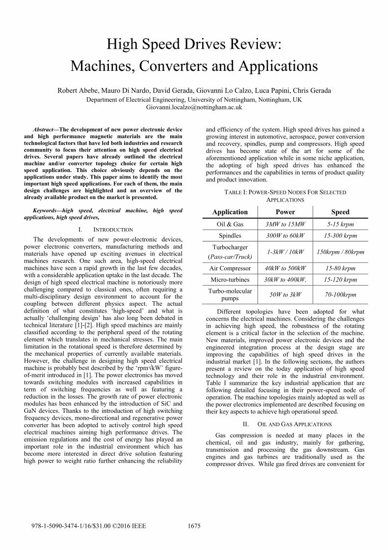
gas companies, they are becoming increasingly difficult to install due to environmental restrictions. The idea of using electric motors to drive compressors to minimize the environmental, regulatory and maintenance issues is not new, but progress in the field of high speed machines have made them more attractive. Oil free compressors have been successfully used for many years but as long as a lubrication system for the oil is still necessary for the drive, or for a gearbox, the benefits of oil-free operation cannot be fully exploited. Electric high speed drives with magnetic bearings allow the elimination of the gearbox and of the entire lubrication oil system, which leads to increased safety, increased efficiency, increased availability as well as to reduced operation and maintenance costs. Thus, the electric high speed drives are the most environmental friendly compressor drives.
Fig. 1. Conventional Compressor (left) and Integrated Compressor (right)
This market is widely dominated by Induction Machines in
the 3MW to 15MW range, with corresponding speeds in the
range 20krpm down to 5krpm [3]. Traditionally solid rotor
machines were considered the most appropriate technology
due to the required high power-speed product [4]. With
special rotor features and high strength electrical steel, the
Laminated Rotor Induction Machine is also becoming
increasingly in this market [5]. While PM machines are
technically capable of achieving some of the power-speed
products for this market, their use is largely disadvantaged
by the amount of magnet required and associated cost and
assembly issues due to the relatively big dimensions of such
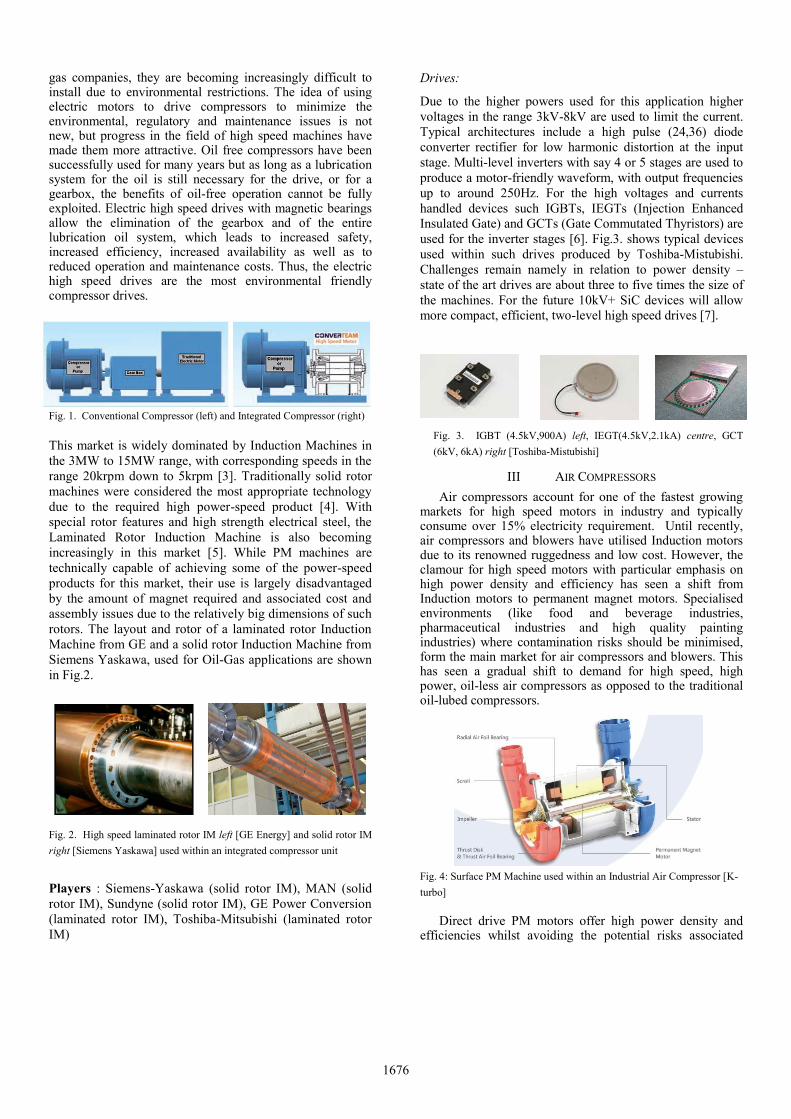
rotors. The layout and rotor of a laminated rotor Induction
Machine from GE and a solid rotor Induction Machine from
Siemens Yaskawa, used for Oil-Gas applications are shown
in Fig.2.
Fig. 2. High speed laminated rotor IM left [GE Energy] and solid rotor IM
right [Siemens Yaskawa] used within an integrated compressor unit
Players : Siemens-Yaskawa (solid rotor IM), MAN (solid
rotor IM), Sundyne (solid rotor IM), GE Power Conversion
Due to the higher powers used for this application higher
voltages in the range 3kV-8kV are used to limit the current.
Typical architectures include a high pulse (24,36) diode
converter rectifier for low harmonic distortion at the input
stage. Multi-level inverters with say 4 or 5 stages are used to
produce a motor-friendly waveform, with output frequencies
up to around 250Hz. For the high voltages and currents
handled devices such IGBTs, IEGTs (Injection Enhanced
Insulated Gate) and GCTs (Gate Commutated Thyristors) are
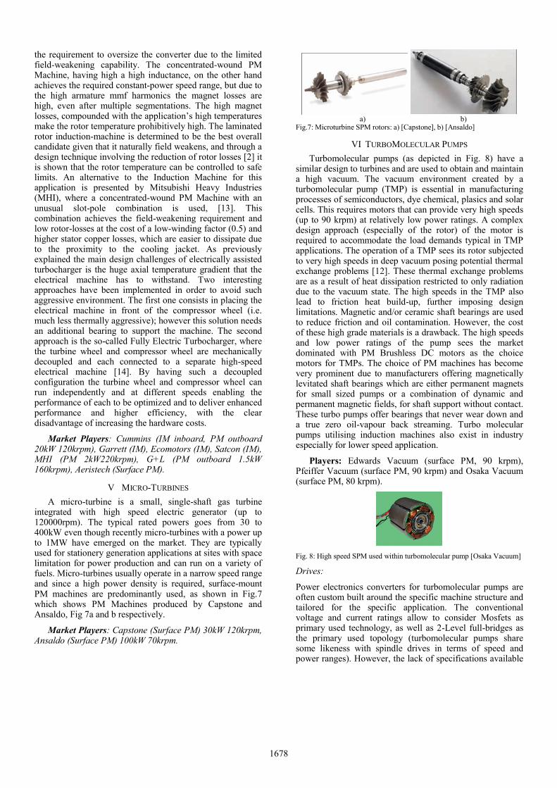
used for the inverter stages [6]. Fig.3. shows typical devices
used within such drives produced by Toshiba-Mistubishi.
Challenges remain namely in relation to power density –
state of the art drives are about three to five times the size of
the machines. For the future 10kV+ SiC devices will allow
more compact, efficient, two-level high speed drives [7].
Fig. 3. IGBT (4.5kV,900A) left, IEGT(4.5kV,2.1kA) centre, GCT
(6kV, 6kA) right [Toshiba-Mistubishi]
III AIR COMPRESSORS
Air compressors account for one of the fastest growing markets for high speed motors in industry and typically consume over 15% electricity requirement. Until recently, air compressors and blowers have utilised Induction motors due to its renowned ruggedness and low cost. However, the clamour for high speed motors with particular emphasis on high power density and efficiency has seen a shift from Induction motors to permanent magnet motors. Specialised environments (like food and beverage industries, pharmaceutical industries and high quality painting industries) where contamination risks should be minimised, form the main market for air compressors and blowers. This has seen a gradual shift to demand for high speed, high power, oil-less air compressors as opposed to the traditional oil-lubed compressors.
Fig. 4: Surface PM Machine used within an Industrial Air Compressor [K-
turbo] Direct drive PM motors offer high power density and
efficiencies whilst avoiding the potential risks associated
1676
with oiled gearboxes and mechanical bearings in induction motors. Figure 4 shows an example of PM air compressor used in industry [8]. The small size requirements for air compressors and blowers also point to PM motors as the choice motors in industry.
Players: K-Turbos (Surface-PM, up to 400kW 65krpm), SKF (Surface-PM, up to 150kW 60krpm, 300kW 30krpm, 70kW 30krpm), Suzler (Surface-PM, 50krpm), Corac (Surface-PM, 150kW 45krpm), CompAir (laminated rotor IM, 300 kW 60krpm), Switch-Yaskawa (solid rotor IM, 300kW 12krpm) and Sundyne (solid rotor IM, 300kW 60krpm).
Although PM motors are more prominent in air compressor and blower applications, some manufacturers use laminated as well as solid rotor Induction Machine technology for this market especially for the higher power ratings.
Drives:
The drive portfolio for compressor applications appears to be quite wide, in particular from the point of view of power electronics topologies. In fact, based on the specific application both conventional 2-Level full-bridge IGBT converters or 3-Level NPC converters using IGBTs or GTOs are used. For higher power levels cascaded 3-Level NPC converter are used to obtain output voltage waveforms with 9 to 17 levels.
IV SPINDLES
Conventional low cost high speed spindles have been historically implemented with belt drives configurations, which are limited in maximum speed. In these applications, high speeds are needed in order to guarantee high volumetric material removal rates, therefore spindles applications have traditionally driven and pushed the research community and industry towards high speed direct drive solutions. Spindle applications can be mainly divided in three areas: milling, grinding and drilling. The maximum rotational speed needed during each of this operation depends on the material under process. Therefore the power range and speed limits in spindle applications are very wide, going from 6000 rpm up to 300000 rpm, with a power approximately from 24 kW down to 200 W [9]. Among the new applications that require very high speed spindles, it is worth to mention the ever increasing speed (up to 1 million rpm) needed for printed-circuit-board (PCB) drilling and the dental surgery tools (up to 400000 rpm, with a power of 10/20 W). The latter have been traditionally implemented through air turbines fed by compressed air; therefore each tool operates at a single speed and several tools with different speeds are needed. By replacing the traditional air turbine tools with electrical drive could reduce the number of tools and add the benefit of having an accurate speed and torque control [10]. Spindle motors typically operate in non-aggressive thermal environments and the main design constraints are high power density, low vibration limit, high dynamic stiffness and the possibility of withstand high axial loads. Most spindle applications require a wide constant power-speed range therefore this market is predominantly IM. For the higher
powers, lower rotational speeds laminated constructions are used, while for the highest rotational speeds, up to 300000rpm copper-coated solid rotor induction machines are typically used (Fig 5) [11]. Due to increasing demands on efficiency and power-density, surface PM are also finding a share of this market especially where the required constant power-speed range is smaller.
Fig 5: Caged solid rotor IM used within high-speed PCB drilling spindle [Westwind]
Players: Mistubishi Electric (laminated IM, 30kW 25krpm, 22kW 30krpm, 7.5kW 60krpm; IPM 7.5kW 60krpm), Air-Bearings Ltd. (solid IM 330W 350krpm, SPM 1.2kW 80krpm), Servax (laminated IM 60kW 27krpm, SPM 53kW 30krpm), Siemens (IM and SPM 18.5 kW 24krpm).
IV ELECTRICALLY ASSISTED TURBOCHARGERS
The concept of placing an electrical machine between the turbine and the compressor wheel (Fig. 6) in a turbocharger is not new. In such configuration the machine can be used as a motor on starting and gear-shift, thus reducing turbo-lag and improving drivability, and as a generator on high engine loads, when there is excess energy in the exhaust gases hence improving efficiencies.
Fig. 6: EAT with electrical machine placed between turbine and compressor [Cummins]
It is well-known that the integration of high speed electrical machines within such an aggressive environment is technically challenging, considering that on engine shutdown the exhaust gas temperatures can be in excess of 800ºC. Another typical design constraint imposed by this application is that the electrical machines needs to achieve a constant power over a wide-speed range.
A number of projects targeting this application have been described in literature. A comprehensive multi-domain topology selection studies for this application is presented in [12] in which the authors compare the suitability of laminated-rotor Induction Machines, distributed-wound surface PM Machine and concentrated-wound surface PM Machines for a 20kW node. The distributed-wound PM Machine achieves highest design-point efficiencies and lowest rotor temperatures, but its application is hindered by
1677
the requirement to oversize the converter due to the limited field-weakening capability. The concentrated-wound PM Machine, having high a high inductance, on the other hand achieves the required constant-power speed range, but due to the high armature mmf harmonics the magnet losses are high, even after multiple segmentations. The high magnet losses, compounded with the application’s high temperatures make the rotor temperature prohibitively high. The laminated rotor induction-machine is determined to be the best overall candidate given that it naturally field weakens, and through a design technique involving the reduction of rotor losses [2] it is shown that the rotor temperature can be controlled to safe limits. An alternative to the Induction Machine for this application is presented by Mitsubishi Heavy Industries (MHI), where a concentrated-wound PM Machine with an unusual slot-pole combination is used, [13]. This combination achieves the field-weakening requirement and low rotor-losses at the cost of a low-winding factor (0.5) and higher stator copper losses, which are easier to dissipate due to the proximity to the cooling jacket. As previously explained the main design challenges of electrically assisted turbocharger is the huge axial temperature gradient that the electrical machine has to withstand. Two interesting approaches have been implemented in order to avoid such aggressive environment. The first one consists in placing the electrical machine in front of the compressor wheel (i.e. much less thermally aggressive); however this solution needs an additional bearing to support the machine. The second approach is the so-called Fully Electric Turbocharger, where the turbine wheel and compressor wheel are mechanically decoupled and each connected to a separate high-speed electrical machine [14]. By having such a decoupled configuration the turbine wheel and compressor wheel can run independently and at different speeds enabling the performance of each to be optimized and to deliver enhanced performance and higher efficiency, with the clear disadvantage of increasing the hardware costs.
A micro-turbine is a small, single-shaft gas turbine integrated with high speed electric generator (up to 120000rpm). The typical rated powers goes from 30 to 400kW even though recently micro-turbines with a power up to 1MW have emerged on the market. They are typically used for stationery generation applications at sites with space limitation for power production and can run on a variety of fuels. Micro-turbines usually operate in a narrow speed range and since a high power density is required, surface-mount PM machines are predominantly used, as shown in Fig.7 which shows PM Machines produced by Capstone and Ansaldo, Fig 7a and b respectively.
a) b) Fig.7: Microturbine SPM rotors: a) [Capstone], b) [Ansaldo]
VI TURBOMOLECULAR PUMPS
Turbomolecular pumps (as depicted in Fig. 8) have a similar design to turbines and are used to obtain and maintain a high vacuum. The vacuum environment created by a turbomolecular pump (TMP) is essential in manufacturing processes of semiconductors, dye chemical, plasics and solar cells. This requires motors that can provide very high speeds (up to 90 krpm) at relatively low power ratings. A complex design approach (especially of the rotor) of the motor is required to accommodate the load demands typical in TMP applications. The operation of a TMP sees its rotor subjected to very high speeds in deep vacuum posing potential thermal exchange problems [12]. These thermal exchange problems are as a result of heat dissipation restricted to only radiation due to the vacuum state. The high speeds in the TMP also lead to friction heat build-up, further imposing design limitations. Magnetic and/or ceramic shaft bearings are used to reduce friction and oil contamination. However, the cost of these high grade materials is a drawback. The high speeds and low power ratings of the pump sees the market dominated with PM Brushless DC motors as the choice motors for TMPs. The choice of PM machines has become very prominent due to manufacturers offering magnetically levitated shaft bearings which are either permanent magnets for small sized pumps or a combination of dynamic and permanent magnetic fields, for shaft support without contact. These turbo pumps offer bearings that never wear down and a true zero oil-vapour back streaming. Turbo molecular pumps utilising induction machines also exist in industry especially for lower speed application.
Fig. 8: High speed SPM used within turbomolecular pump [Osaka Vacuum]
Drives:
Power electronics converters for turbomolecular pumps are often custom built around the specific machine structure and tailored for the specific application. The conventional voltage and current ratings allow to consider Mosfets as primary used technology, as well as 2-Level full-bridges as the primary used topology (turbomolecular pumps share some likeness with spindle drives in terms of speed and power ranges). However, the lack of specifications available
1678
from the producers does not allow to provide something different from a mere consideration.
VII CONCLUSION
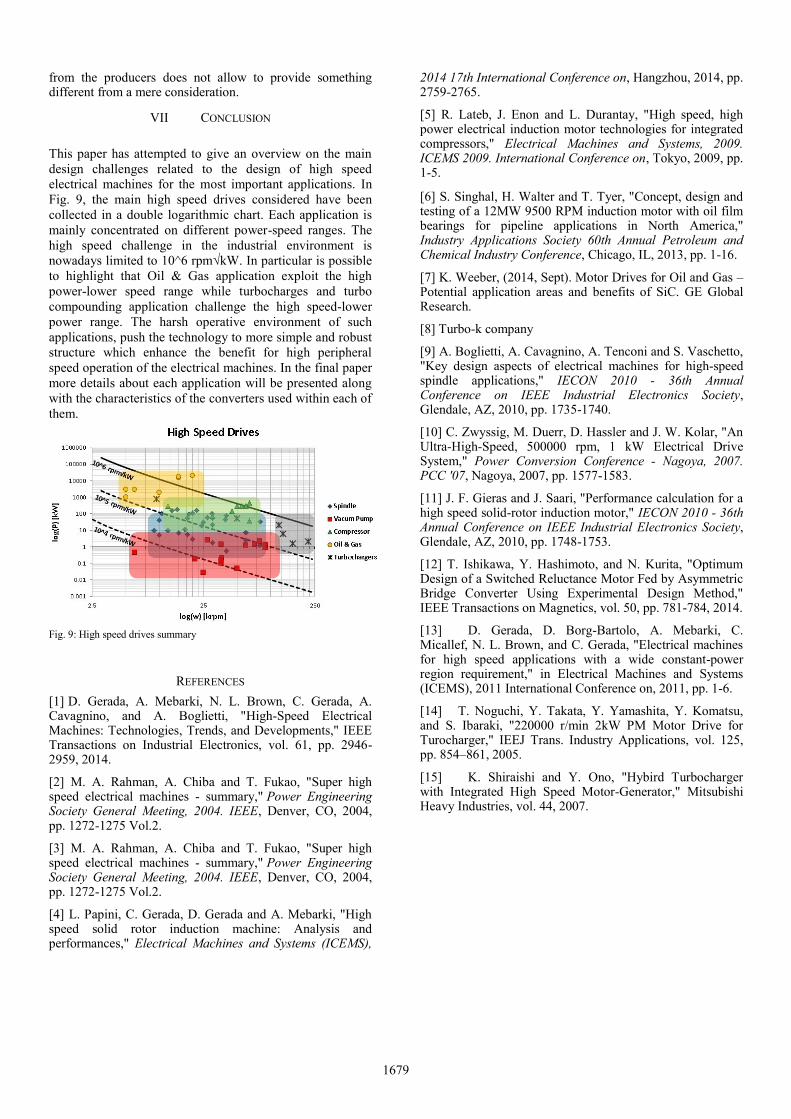
This paper has attempted to give an overview on the main
design challenges related to the design of high speed
electrical machines for the most important applications. In
Fig. 9, the main high speed drives considered have been
collected in a double logarithmic chart. Each application is
mainly concentrated on different power-speed ranges. The
high speed challenge in the industrial environment is
nowadays limited to 10^6 rpm√kW. In particular is possible
to highlight that Oil & Gas application exploit the high
power-lower speed range while turbocharges and turbo
compounding application challenge the high speed-lower
power range. The harsh operative environment of such
applications, push the technology to more simple and robust
structure which enhance the benefit for high peripheral
speed operation of the electrical machines. In the final paper
more details about each application will be presented along
with the characteristics of the converters used within each of
them.
Fig. 9: High speed drives summary
REFERENCES
[1] D. Gerada, A. Mebarki, N. L. Brown, C. Gerada, A. Cavagnino, and A. Boglietti, "High-Speed Electrical Machines: Technologies, Trends, and Developments," IEEE Transactions on Industrial Electronics, vol. 61, pp. 2946-2959, 2014.
[2] M. A. Rahman, A. Chiba and T. Fukao, "Super high speed electrical machines - summary," Power Engineering Society General Meeting, 2004. IEEE, Denver, CO, 2004, pp. 1272-1275 Vol.2.
[3] M. A. Rahman, A. Chiba and T. Fukao, "Super high speed electrical machines - summary," Power Engineering Society General Meeting, 2004. IEEE, Denver, CO, 2004, pp. 1272-1275 Vol.2.
[4] L. Papini, C. Gerada, D. Gerada and A. Mebarki, "High speed solid rotor induction machine: Analysis and performances," Electrical Machines and Systems (ICEMS),
2014 17th International Conference on, Hangzhou, 2014, pp. 2759-2765.
[5] R. Lateb, J. Enon and L. Durantay, "High speed, high power electrical induction motor technologies for integrated compressors," Electrical Machines and Systems, 2009. ICEMS 2009. International Conference on, Tokyo, 2009, pp. 1-5.
[6] S. Singhal, H. Walter and T. Tyer, "Concept, design and testing of a 12MW 9500 RPM induction motor with oil film bearings for pipeline applications in North America," Industry Applications Society 60th Annual Petroleum and Chemical Industry Conference, Chicago, IL, 2013, pp. 1-16.
[7] K. Weeber, (2014, Sept). Motor Drives for Oil and Gas – Potential application areas and benefits of SiC. GE Global Research.
[8] Turbo-k company
[9] A. Boglietti, A. Cavagnino, A. Tenconi and S. Vaschetto, "Key design aspects of electrical machines for high-speed spindle applications," IECON 2010 - 36th Annual Conference on IEEE Industrial Electronics Society, Glendale, AZ, 2010, pp. 1735-1740.
[10] C. Zwyssig, M. Duerr, D. Hassler and J. W. Kolar, "An Ultra-High-Speed, 500000 rpm, 1 kW Electrical Drive System," Power Conversion Conference - Nagoya, 2007. PCC '07, Nagoya, 2007, pp. 1577-1583.
[11] J. F. Gieras and J. Saari, "Performance calculation for a high speed solid-rotor induction motor," IECON 2010 - 36th Annual Conference on IEEE Industrial Electronics Society, Glendale, AZ, 2010, pp. 1748-1753.
[12] T. Ishikawa, Y. Hashimoto, and N. Kurita, "Optimum Design of a Switched Reluctance Motor Fed by Asymmetric Bridge Converter Using Experimental Design Method," IEEE Transactions on Magnetics, vol. 50, pp. 781-784, 2014.
[13] D. Gerada, D. Borg-Bartolo, A. Mebarki, C. Micallef, N. L. Brown, and C. Gerada, "Electrical machines for high speed applications with a wide constant-power region requirement," in Electrical Machines and Systems (ICEMS), 2011 International Conference on, 2011, pp. 1-6.
[14] T. Noguchi, Y. Takata, Y. Yamashita, Y. Komatsu, and S. Ibaraki, "220000 r/min 2kW PM Motor Drive for Turocharger," IEEJ Trans. Industry Applications, vol. 125, pp. 854–861, 2005.
[15] K. Shiraishi and Y. Ono, "Hybird Turbocharger with Integrated High Speed Motor-Generator," Mitsubishi Heavy Industries, vol. 44, 2007.