24
High-speed & high-productivity horizontal machining center

High-speed & high-productivity horizontal machining center

02
The NHP series offers a high level of productivity by a combination of heavy duty cutting
and high speed machining capability. The single-piece bed structure and stepped
guideway for the X-axis enhances rigidity and improves rapid traverse characteristics.
The machines include a best in class specification and a wide variety of features to
optimize performance and provide easy operation.
World-class high-speed & high-productivity horizontal machining center

03
The single piece bed structure is optimized through structural analysis. This provides a high level of stability which guarantees best possible accuracy and heavy duty cutting capability. The reduced mass of the travelling column means that acceleration/ deceleration axis rates are optimized.
Rigid structure1
The machine performance has been improved over the previous model by 8% due to upgraded axis rapid traverse rates and improved ATC/APC times. In addition, many functions have been included to make operating more convenient.
The ATC and APC systems are based on the latest servo technology. This provides a high level of reliability and makes maintenance easier at the customer's site.
High reliability2
3 High productivity & Operator convenience
NHP 5500 / 6300
Previous model
900 s
977 s
77 s77 s
Down
8
•Cycle time
Features
NHP series(Single-piece bed structure)

04
Rigid Structure
NHP 5500/6300/8000
The NHP series includes a one piece bed structure with heavy duty mehanite ribbed castings designed for optimized rigidity and stability.
Rigid Structure
All X, Y, Z axes are designed with roller LMG specification. The front rail of the X axis has LMG roller blocks for maximum rigidity. In addition, the spindle rigidity is optimized by using a stepped X axis guideway which reduces the distance from the spindle to the guideways. The stable structure and reduced column mass provides high axis rapid traverse rates and top class acceleration/deceleration values.
Stepped guide-type rigid bed
Minimum Thermal Displacement for High AccuracyIn
Shaft cooling
Out
Nut cooling
Main units of the X, Y and Z axes are designed to minimize the thermal displacement by applying cooling jackets to ball screw nut and ball screw shaft cooling.
Oil Cooler

05
Travel (X/Y/Z)
NHP 5500
800/750/850 mm(31.5/29.5/33.5 inch)
Previous model
800/700/750 mm(31.5/27.6/29.5 inch)
Previous model
1000/850/850 mm(39.4/33.5/33.5 inch)
1050/900/1000 mm(41.3/35.4/39.4 inch)
NHP 6300
1400/1200/1370 mm(55.1/47.2/53.9 inch)
NHP 8000
Double Wall Structure
The body of the machine is designed to have a double-wall structure to prevent cutting oil from leaking. This helps maintain the machine more easily and enhance productivity.
• New oil leakage prevention mechanism
The short minimum distance from the spindle nose to table means that tool lengths can be optimized for a rigid machining setup.
Spindle Close Reach to Table Center
150 mm(5.9 inch)
NHP 5500/6300
NHP 8000
Previous model
100 mm
150 mm
33 %
Rapid traverse (X/Y/Z)
Previous model
48/48/48 m/min(1889.8/1889.8/1889.8 ipm)
NHP 5500/6300
25%60/60/60 m/min
(2362.2/2362.2/2362.2 ipm)
NHP 8000
50/50/50 m/min(1968.5/1968.5/1968.5 ipm)
(3.9 inch)
(5.9 inch)

06
High Performance Spindle
NHP 5500/6300/8000
High Speed High Performance Spindle
The NHP series is equipped with a 50 taper spindle. The spindle includes a rigid 4 row large diameter angular contact bearing structure permanently supplied by lubricant(grease or oil). The built in motor design includes a dual motor winding system which offers a 2 step virtual gearbox, thereby providing high torque at low spindle speed. In addition, the built in motor design provides a fast acceleration/deceleration rate for spindle start/stop.
The high torque built-in motor type spindle provides a combination of high rigidity and high speed.
Unit Previous model NHP 5500 / 6300 / 8000
Max. spindle speed r/min
10000 10000
6000 6000
12000 15000
Motor power kW (lb)
30 / 22 (40.2 / 29.5) 45 / 25 (60.3 / 33.5) ( 10000 r/min)Motor power enhanced by 50% compared to the previous model
30 / 22 (40.2 / 29.5) 37 / 25 (49.6 / 33.5) ( 6000 r/min)
30 / 25 (40.2 / 33.5) 37 / 30 (49.6 / 40.2) ( 15000 r/min)
Max. torque N·m (ft·lb)
301.8 (222.7) (15% ED) 600 (442.8) (at 45kW, S3 15%)Main spindle torque enhanced by 99% compared to the previous model
599.8 (442.7) (15% min.) 809 (597.0) (at 37kW, S3 15%)
420.4 (310.3) (25% ED) 398 (293.7) (at 37kW, S3 25%)

07
2-Face Locking Tool System
The 2-face locking tool system offers longer tool life, higer power and more precise machining by the dual contact to both of the spindle surface and toolholder flange surface, as well as both the spindle taper and toolholder taper shank. This system is based on the most currently available standards of BT50, DIN50, CAT50 and HSK-A100 flange tooling.
The refrigerated cooling system maintains a uniform spindle temperature required for optimum accuracy. The cooling oil circulates around the bearings and motor windings.
Taper contact
Flange contact
Tool Clamping Spindle Cooling System
• Higher rigidity• Improved ATC repeatability, surface finish and
higher precision• Extending tool life
Key benefits
HSK Holder (optional)High Precision, High Efficiency, High QualityThis holder helps keep productivity and precision at high levels when machining curved surfaces or high value & difficult-to-cut materials (high performance parts). Also, as it disperses cutting heat along with chips, the holder helps minimize deformation of workpiece.
20000 N(4496.0 lbs)
NHP 5500/6300/8000Previous model
24500 N (5507.6 lbs)(10000 r/min, 15000 r/min)
26500 N (5957.2 lbs)(6000 r/min)
08
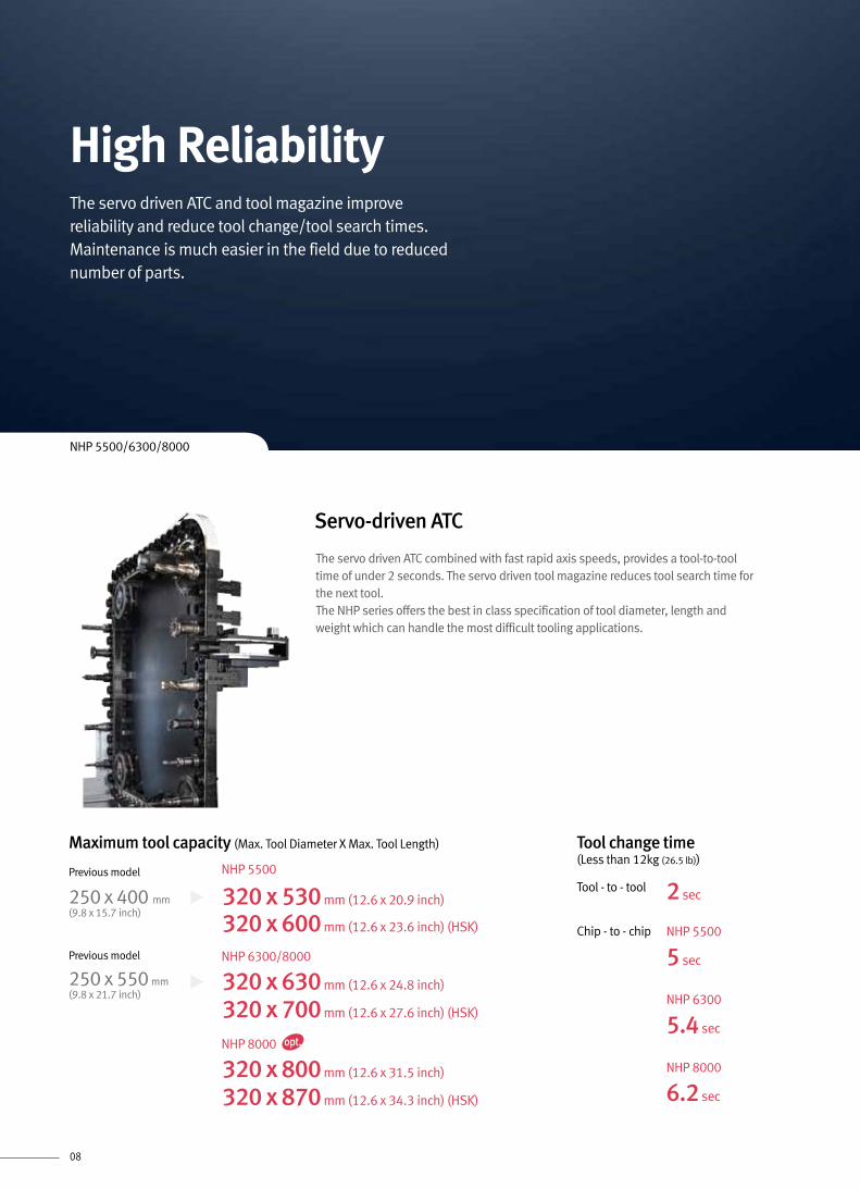
High Reliability
NHP 5500/6300/8000
Servo-driven ATC
2 secTool - to - tool
Chip - to - chip
5.4 sec
NHP 6300
6.2 sec
NHP 8000
5 sec
NHP 5500
Tool change time (Less than 12kg (26.5 lb))
The servo driven ATC combined with fast rapid axis speeds, provides a tool-to-tool time of under 2 seconds. The servo driven tool magazine reduces tool search time for the next tool.The NHP series offers the best in class specification of tool diameter, length and weight which can handle the most difficult tooling applications.
The servo driven ATC and tool magazine improve reliability and reduce tool change/tool search times. Maintenance is much easier in the field due to reduced number of parts.
Maximum tool capacity (Max. Tool Diameter X Max. Tool Length)
Previous model
250 x 400 mm(9.8 x 15.7 inch)
Previous model
250 x 550 mm(9.8 x 21.7 inch)
NHP 5500
320 x 530 mm (12.6 x 20.9 inch)
320 x 600 mm (12.6 x 23.6 inch) (HSK)
NHP 6300/8000
320 x 630 mm (12.6 x 24.8 inch)
320 x 700 mm (12.6 x 27.6 inch) (HSK)
NHP 8000
320 x 800 mm (12.6 x 31.5 inch)
320 x 870 mm (12.6 x 34.3 inch) (HSK)

09
Tool Magazine
The NHP series provide 40 tools in its standard specifications and allow you to use up to 376 tools in optional specifications.
Chain type magazinePot moving type magazine Matrix type magazine
Previous model
90/120 ea
NHP 5500/6300/8000
90/120/150 ea
40/60 ea
Previous model
NHP 5500/6300/8000
40 ea 60 ea
196/256/324 ea
Previous model
NHP 5500/6300/8000
196/256/316/376 ea

10
NHP 5500/6300/8000
The NHP series is equipped with a servo-driven rotary type pallet change system which achieves higher reliability than a hydraulic version. In addition, higher workpiece loads can be handled efficiently.
WH
D
Servo-Driven APC
The NHP series' servo-driven automatic pallet changer offers high productivity by fast pallet changing. The wide door opening allows easy access for the operator to reach the fixture and workpiece. The pallet can be manually indexed to 90 degree positions for access to all sides of the fixture.
NHP 5500 NHP 6300 NHP 8000
Pallet change time 8.5 s 12 s 16 s
Pallet indexing (0->90deg.) 1.7 s 2.4 s 3.2 s
Enhanced APC system and Pallet
Accurate Control of Pallet Position.
Chips may reduce the accuracy of the pallet changing system. A high pressure air blast is used to clean the taper cone location surfaces during the pallet change cycle.
(unit : second)

11
• Oil & air pressure ports
- A/B Line : 2, 4, 6, 8 Pairs
(includes solenoid valve)
- P/T Line : 2, 4, 6, 8 Pairs
(does not include a solenoid valve)
Fixture Features
You can select one of the following oil & air pressure devices that can be easily set up.
Fixture check list (for hydraulic/pneumatic fixtures)
Max. workpiece size (DXH)
Previous model
Ø 800 x 950 mm(Ø 31.5 x 37.4 inch)
Previous model
Ø 1000 x 1150 mm(Ø 39.4 x 45.3 inch)
NHP 5500
Ø 850 x 1100 mm(Ø 33.5 x 43.3 inch)
Ø 1050 x 1350 mm(Ø 41.3 x 53.1 inch)
NHP 6300
Ø 1450 x 1550 mm(Ø 57.1 x 61.0 inch)
NHP 8000
Max. workpiece weight (W)
Previous model
800 kg(1763.7 lb)
Previous model
1200 kg(2645.5 lb)
NHP 5500
800 kg(1763.7 lb)
2000 kg(4409.2 lb)
NHP 8000
1500 kg
NHP 6300
300 kg
• Hydraulic power unit
- 2.2 kW / 7 MPa (3.0 Hp / 1015.0 psi / bar)
- 3.7 kW / 15 MPa (5.0 Hp / 2175.0 psi / bar)
- 5.5 kW / 21 MPa (7.4 Hp / 3045.0 psi / bar)
• Contact Doosan for more information
(3306.9 lb)(661.4 lb)
Hydraulically actuated fixtures remain permanently connected during machine operation and APC cycle. This is achieved by using hydraulic rotary couplings in the central APC mechanism and also on top of both fixtures. A cantilever system supports the hydraulic lines during the machining operation.

12
• Easily extendable up to 3 HMCs, 2 setup stations• Highly efficient use of workpiece area• Quick installation and sufficient time for test operation• Modular rack system that can be adjusted in response to changing production volumes• Stable and efficient system operation• Easy-to-use operation system• Easy to maintain in the field
LPS is designed to provide the most optimized system for the customer.The customer can choose the package solution most suitable for their production requirements and floorspace. System expansion and changes in layout are easy
12 Pallet x 1 set up x 1 Machine 36 Pallet x 2 set up x 3 Machine24 Pallet x 2 set up x 2 Machine
* For further information and more details, contact Doosan.
Number of machines
Number of pallets
Number of setup stations
LPS 630 (Model : NHP 6300)
1
10 20 30
1 1 2 1 2
2
20 30
1 2 1 2
3
30
1 2ea
ea
ea
Number of machines
Number of pallets
Number of setup stations
LPS 800 (Model : NHP 8000)
1
8 16 24
1 1 2 1 2
2
16 24
1 2 1 2
3
24
1 2ea
ea
ea
Number of machines
Number of pallets
Number of setup stations
LPS 500 (Model : NHP 5500)
1
12 24 36
1 1 2 1 2
2
24 36
1 2 1 2
3
36
1 2
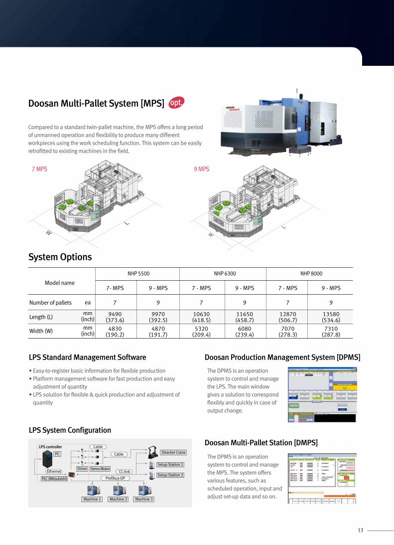
System Options
ea
ea
ea
Unit : mm (inch)
Doosan Linear Pallet System [LPS]
Pallet Expansion System
7050 (277.6)
2945
(115
.9)
3300(129.9)
12900 (507.9)
2945
(115
.9)
3300(129.9)
18780 (739.4)
2945
(115
.9)
3300(129.9)
13
Compared to a standard twin-pallet machine, the MPS offers a long period of unmanned operation and flexibility to produce many different workpieces using the work scheduling function. This system can be easily retrofitted to existing machines in the field.
Doosan Multi-Pallet System [MPS]
LPS Standard Management Software Doosan Production Management System [DPMS]
Doosan Multi-Pallet Station [DMPS]
• Easy-to-register basic information for flexible production• Platform management software for fast production and easy
adjustment of quantity• LPS solution for flexible & quick production and adjustment of
quantity
The DPMS is an operation system to control and manage the LPS. The main window gives a solution to correspond flexibly and quickly in case of output change.
The DPMS is an operation system to control and manage the MPS. The system offers various features, such as scheduled operation, input and adjust set-up data and so on.
LPS System Configuration
Model name
Number of pallets
Length (L)mm
(inch)
mm(inch)
ea
Width (W)
NHP 5500 NHP 6300 NHP 8000
7- MPS 9 - MPS
7 9
9490(373.6)
9970(392.5)
4830(190.2)
4870(191.7)
7 - MPS 9 - MPS
7 9
10630(418.5)
11650(458.7)
5320(209.4)
6080(239.4)
7 - MPS 9 - MPS
7 9
12870(506.7)
13580(534.6)
7070(278.3)
7310(287.8)
System Options
WL
WL
7 MPS 9 MPS
LPS controller
Machine 1 Machine 2 Machine 3
Profibus-DP
Ethernet
Cable
Cable
Driver
PC
Servo Motor
Stracker Crane
Setup Station 1
Setup Station 2CC-link
PLC (Mitsubishi)

14
Machine performance enhanced by 8% compared to the previous model due to reduction in non-cutting time
Enhanced by 8% compared to the previous model
NHP 5500 / 6300
Previous model
900 s
977 s
77 s77 s
Down
8
• Cycle time
• Diesel engine cylinder block
• Material : Casting iron
• Number of used tools : 20ea
Productivity
Machining rate
M42×P4.5Main spindle speed
150 r/minFeed rate675 mm/min(26.6 ipm)
Tap_carbon steel (SM45C) [ø85mm (3.4 inch) U-Drill (2Z)]
Cutting quantity567 cm3/min(34.6 inch3/min)
Main spindle speed
600 r/minFeed rate100 mm/min(3.9 ipm)
Drill_carbon steel (SM45C)
100mm
8mm8mm(0.3inch)(0.3inch)
(3.9inch)
(3.2inch)
(3.4inch)
100mm100mm
100mm
8mm8mm(0.3inch)(0.3inch)
(3.9inch)100mm100mm
80mm80mm
85mm85mm
50mm50mm
50mm50mm
Cutting quantity 440 cm3/min(26.9 inch3/min)
700 cm3/min(42.7 inch3/min)
Main spindle speed 350 r/min 500 r/min
Feed rate 550 mm/min(21.7 ipm)
1400 mm/min(55.1 ipm)
Previous model
(Motor power : 45/25 kW (24.8/20.1 Hp))NHP 5500/6300/8000
[ø125mm (4.9inch) Face mill (8Z)]Face mill_carbon steel (SM45C)
100mm
8mm8mm(0.3inch)(0.3inch)
(3.9inch)
(3.2inch)
(3.4inch)
100mm100mm
100mm
5mm5mm(0.19inch)(0.19inch)
(3.9inch)100mm100mm
80mm80mm
85mm85mm
50mm50mm
50mm50mm
Machining Performance
High Productivity & User Convenience
NHP 5500/6300

15
Easy-to-Use Chip Conveyor
Removing chips is very important in terms of productivity and environmental protection. To achieve these goals, the NHP series use a flushing device to remove chips from the inside of the equipment as a standard and help improve the process of chip removal with a screw conveyor of extended diameter.
Coolant DevicesFlushing coolant Flood coolant
Chip conveyor & coolant tank
Scraper type Drum filter type
Hinge type
Screw conveyor
Large capacity coolant tank
Previous model
630 L(166.4 galon)
NHP 5500
825 L 31 %
Previous model
630 L(166.4 galon)
NHP 6300/8000
925 L 47 %
Flushing for the top of the spindle
Through spindle coolant MQL systemSemi Permanent TSC pump unit
Air+Oil mist Misting device
Coolant gunShower coolant
Measuring Device
Environmentally-friendly equipment
Auto. tool breakage detection l
Auto. tool breakage detection ll
Auto. tool measurement detection
U-axis tool applicationOil mist collectorOil skimmer
(218.0 galon)
(244.4 galon)

16
Improved Usability
Oil skimmer
Utilities in the same place
Anti-lock mechanismInternal footplate for operator safety
The T-S-C mechanism uses semi-permanent cyclone filters to save cost and improve usability.
A coolant flush is installed on the top of the spindle and the slide cover to prevent chips from building up.
New HMC ATC screen panel operation
Centralized service unitThe service units are stored in the same place to make it easier to maintain the machine.
Operator-Friendly DesignTo ensure safety for users, footsteps, anti-lock mechanism, and screen panels are installed

17
90°
Swivelling operating console
The operation panel can be rotated by up to 90 degrees for convenient operator position. The control provides a wide selection of detailed alarm messages which makes fault-finding easier for better usability.
Portable MPG
PCMCIA Card
The portable MPG allows you to set a workpiece more easily.
PCMCIA card input allows the upload/download of NC programs, parameters, tool data and ladder diagrams. It also supports DNC operation.
User-Friendly Operation PanelConsolidate a variety of control panel into unified concept design to provide convenience of operation
Fixture clamp/unclamp button counter, timer or special option buttons can be placed on the panel.
Partitions are placed between all buttons to prevent pushing an unintended button.
Easy-to-Use Operation Panel
USB Ports
With a USB memory stick, you can upload and download NC programs, NC parameters, tool information and ladder programs, but cannot operate the DNC

18
Easy Operation Package
Help
Easy NC parameter• Help topics on main parameters• Display parameter setting values
G code list• Main G CODE list
Calculator• Calculator• Four basic operations• Mathematical functions
M code list• Main M CODE list
Tool Support
Tool management I• Manage tool magazines• Display tool status• Fastems MMS I/F (Tool Add/
Remove Function)
ATC/APC panel• ATC manual• APC manual
Tool management II• Manage tool magazines• Self-manage tool life• Estimate tool life• Manage tool status• Balluff Tool ID
• Detect tool damage• Detect errors during machining• Detect no-load air cutting
Tool load monitor
Doosan’s easy-to-use operation package offers a variety of features, to support tool management, pallet management and operator help functions
Operation
Operation rate• Measure various equipment
operation ratios• Support a three-shift system• Count and keep 30-day
operation ratios• Display specific date ranges
APC setting• Control display for 2 Pallet APC
PMC switch• Optional features on the
operation panel• Substitute for toggle
software• Software for NC options
Pallet Magazine
• Operate the MPS• Display information for MPS
PMG• Set a machining schedule• Auto call• Manual operation and
coordinate adjustment
Multi-pallet System

19
Spindle Power-Torque Diagram
NHP 5500/6300/8000
809 (597.0)746 (550.5)600 (442.8)
421 (310.7)
37 (49.6)30 (40.2)25 (33.5)22 (29.5)18.5 (24.8)15 (20.1)
294 (217.0)239 (176.4)201 (148.3)175 (129.2)
103 (76.0)90.3 (66.6)
66.8 (49.3)
29.4 (21.7)23.9 (17.6)
295
350
420
600
800
865
1200
2000
2500
3000
4000
5000
6000
SPINDLE 6000 r/min(Motor : BiI180L / 6000 AMP : aiSP30)
SPINDLE SPEED (r/min)
S3 15%
S3 25% S3 25%S2 15min. S2 30min.
S2 15min.
S1 Cont.S1 Cont.
S1 Cont.
S3 15%S3 25%
Torque : N·m (ft·lb) Power : kW (Hp)
398 (293.7)
263 (194.1)
191 (141.0)
37 (49.6)30 (40.2)25 (33.5)22 (29.5)20.3 (27.2)
15 (20.8)15 (20.1)168 (124.0)
60 (44.3)
12.9 (9.5)9.9 (7.3)
600
800
1000
1500
2100
3000
2500
6000
1000
0
1300
015
000
SPINDLE 15000 r/min(Motor : BiI160LL / 20000 AMP : aiSP37)
SPINDLE SPEED (r/min)
S3 25% S3 25%
S2 15min.
S1 Cont.
S1 Cont.
S3 25%S2 10min.S1 Cont.
Torque : N·m (ft·lb) Power : kW (Hp)
Torque : N·m (ft·lb) Power : kW (Hp)
600 (442.8)553 (408.1)420 (310.0) 45 (60.3)
37 (49.6)30 (40.2)25 (33.5)22 (29.5)18.5 (24.8)15 (20.1)
305 (225.1)
153 (112.9)126 (93.0)115 (84.9)
95.5 (70.5)88.3 (65.2)71.6 (52.8)
28.6 (21.1)23.9 (17.6)
350
380
500
580
1000
1500
2000
2500
2800
4000
7000
1000
0
SPINDLE 10000 r/min(Motor : BiI160LL / 13000 AMP : aiSP37)
SPINDLE SPEED (r/min)
S3 15%
S3 25% S3 25%S2 15min.
S2 30min.S2 15min.
S2 15min.
S1 Cont.S1 Cont.
S1 Cont.
S3 15%S3 25%

20
NHP 5500
NHP 8000
Unit : mm (inch)
Table Dimension
Standard specification (500×500)
25(1.0)
18(0.7) 36
(1.4)
75 (3.0) 75 (3.0) HOLE FOR M16
24-M16X2 TAP, DP30
50(2.0)
50(2.0)
500 (19.7)
500 (19.7)
100 (3.9)
100 (3.9)
Optional specifications (630×630)
100 (3.9) 100 (3.9) HOLE FOR M16
25(1.0)
18(0.7) (0.7)
18
24-M16X2 TAP, DP30
630 (24.8)
65(2.6)
65(2.6)
630 (24.8)125 (4.9)
125 (4.9)
NHP 6300 Standard specification (630×630)
100 (3.9) 100 (3.9) HOLE FOR M16
24-M16X2 TAP, DP30
65(2.6)
630 (24.8)
125 (4.9)
630 (24.8)
65(2.6)
125 (4.9)
25(1.0)
18(0.7) 36
(1.4)
Optional specifications (800×800)
135 (5.3) 135 (5.3) HOLE FOR M16
25(1.0)
18(0.7) 36
(1.4)
24-M16X2 TAP, DP30
80(3.1)
800 (31.5)
160 (6.3)
800 (31.5)
80(3.1)
160 (6.3)
160 (6.3)
160 (6.3)
80(3.1)
80(3.1)
800 (31.5)
800 (31.5)
135 (5.3) 135 (5.3)40(1.6)
40(1.6)
18 (0.7)36 (1.4)
720 (28.3)Ø25
(1.0)
18(0.7)

21
Unit : mm (inch)
External Dimensions
Maximum Tool & Workpiece diagram
Model A B C C D E F G H I J K L M N O
NHP 5500 Ø850 (33.5)
Ø320(12.6)
130(5.1)
168(6.6)
530(20.9)
400(15.7)
800(31.5)
1100(43.3)
850(33.5)
100(3.9)
5(0.2)
750 (29.5)
75(3.0)
230(9.1)
Ø260(10.2)
Ø320(12.6)
NHP 6300 Ø1050(41.3)
Ø320(12.6)
95(3.7)
168(6.6)
630(24.8)
525(20.7)
1050(41.3)
1350(53.1)
1000(39.4)
100(3.9)
55(2.2)
900(35.4)
75(3.0)
230(9.1)
Ø260(10.2)
Ø320(12.6)
NHP 8000 Ø1450(57.1)
Ø320(12.6)
65(2.6)
168(6.6)
630(24.8)
700(27.6)
1400(55.1)
1550(61.0)
1370(53.9)
150(5.9)
5(0.2)
1200(47.2)
75(3.0)
230(9.1)
Ø260(10.2)
Ø320(12.6)
G
LK
J
H I
N
O
M
EF
B
A A
DC
Y-AX
IS S
TRO
KE
Z-AXIS STROKE
X-AX
IS S
TRO
KE
MAX WORK
DIA.
N
K
G
L
H
J
M
O
I
EF
C D
B
A A
Y-AX
IS S
TRO
KE
Z-AXIS STROKE
X-AX
IS S
TRO
KE
MAX WORK DIA.
G
L
H
O
N
K
M
J
EF
B
A A
Y-AX
IS S
TRO
KE
Z-AXIS STROKE
X-AX
IS S
TRO
KE
MAX WORK DIA.
DCI
GH
I
B C D
615
660
EF
A
(PDP
BO
X DO
OR)
Model A B C D E (40T) F (60T) G (90T) H (120T) I (150T)
NHP 5500 3670(144.5)
5101(200.8)
935(36.8)
776(30.6)
3767(148.3)
5101(200.8)
5723(225.3)
6505(256.1)
7273(286.3)
NHP 6300 3930(154.7)
5571(219.3)
950(37.4)
776(30.6)
4237(166.8)
5143(202.5)
6193(243.8)
6975(274.6)
7743(304.8)
NHP 8000 4375(172.2)
6595(259.6)
950(37.4)
776(30.6)
5262(207.2)
6596(259.7)
7218(284.2)
8000(315.0)
8768(345.2)
Top View

22
• Coolant tank & chip fan
• Equipment status light
• Machine installation parts
• Oil skimmer
• Screw conveyor
• Spindle head cooling system
• Work light
Standard Feature• Air gun
• Auto power cutoff device
• Auto tool length measurement device
• Auto workpiece measurement device
• Chip conveyor / Bucket
• Coolant gun
• Hyd. Fixture Interface
• Linear scale
• Shower Coolant
• Test bar
• 5axis preparation
- Through spindle coolant (In case of water soluble)
Type Frequency(HZ) Flux(L/min) Pressure(MPa)1.9 MPa
T.S.C50 8 1.76 (255.2 psi)60 10 1.91 (277.0 psi)
2.94 MPaT.S.C
50 12 2.74 (397.3 psi)
60 16 2.94 (426.3 psi)
6.86 MPaT.S.C
50 22 6.86 (994.7 psi)60 30.7 6.86 (994.7 psi)
Optional Feature
Machine Specifications
Features Unit NHP5500 NHP6300 NHP8000
Machining Capacity
Travel distance
X-axis mm (inch) 800 (31.5) 1050 (41.3) 1400 (55.1)Y-axis mm (inch) 750 (29.5) 900 (35.4) 1200 (47.2)Z-axis mm (inch) 850 (33.5) 1000 (39.4) 1370 (53.9)
Distance from the spindle center to the top of the table
mm (inch) 75 - 825 (3.0 - 32.5) 75 - 975 (3.0 - 38.4) 75 - 1275 (3.0 - 50.2)
Distance from the spindle nose to the table center
mm (inch) 100 - 950 (3.9 - 37.4) 100 - 1100 (3.9 - 43.3) 150 - 1520 (5.9 - 59.8)
Pallet
Pallet type 24-M16×P2.0Pallet indexing angle deg 1 {0.001}Max. allowable load kg (lb) 800 (1763.7) 1500 (3306.9) 2000 (4409.2)Max. workpiece size mm 850×1100 (33.5×43.3) 1050×1350 (41.3×53.1) 1450×1550 (57.1×61.0)Pallet size mm 500×500 (19.7×19.7) 630×630 (24.8×24.8) 800×800 (31.5×31.5)
Main spindleMax. spindle speed r/min 10000 {6000, 15000}Taper specifications ISO #50, 7/24 TAPERMax. torque N·m (ft·lb) 600 {809, 398} (442.8 {597.0, 293.7})
Feed rate
Rapid Traverse Rate
X-axis m/min (ipm) 60 (2362.2) 50 (1968.5)Y-axis m/min (ipm) 60 (2362.2) 50 (1968.5)Z-axis m/min (ipm) 60 (2362.2) 50 (1968.5)
Cutting feedrate mm/min (ipm) 30000 (1181.1) 25000 (984.3)
Automatic Pallet Changer
Number of pallets ea 2Pallet change method Rotary shuttlesPallet change time s 8.5 12 16Indexing angle when APC rotates deg 90
Automatic Tool Changer
Type of tool shank BT50 {CAT50/DIN50/HSK-A100}Tool storage capa.
Pot moving Type ea 40 {60}Chain Type ea {90/120/150}Matrix Type ea {196/256/316/376}
Max. tool diameter
40/60tools mm (inch) 125 (4.9) (continous.) (40/60 tools), 130 (5.1) (continous.) (90-376 tools)90~376tools mm (inch) 320 (12.6) (adjacent pots empty)
Max. tool length mm (inch)530 (20.9) (BT/CAT/DIN),
600 (23.6) (HSK)630 (24.8) (BT/CAT/DIN),
700 (27.6) (HSK)
630 (800) (24.8 (31.5)) (BT/CAT/DIN),
700 {870)(27.6 {34.3}) (HSK)Max. tool weight kg (lb) 25 (55.1) (40/60 tools), 30 (66.1) (90-376 tools)Tool change time (Tool-to-tool, less than 12kg) s 2Tool change time (Chip-to-chip, less than 12kg) s 5 5.4 6.2
MotorsSpindle motor power kW (Hp) 45/25 {37/25, 37/30} (60.3/33.5 {49.6/33.5, 49.6/40.2})Coolant pump motor power kW (Hp) 1.5 (2.0)
Power sourceElectric power supply (rated capacity) kVA 79 76 112Compressed air supply Mpa (psi) 0.54 (78.3)
Tank capacityCoolant tank capacity L (galon) 825 (218.0) 925 (244.4)Lubrication tank capacity L (galon) 7.2 (1.9)
Machine Dimensions
Height mm (inch) 3270 (128.7) 3420 (134.6) 3760 (148.0)Length mm (inch) 6035 (237.6) 7300 (287.4) 8350 (328.7)Width mm (inch) 3670 (144.5) 3930 (154.7) 4325 (170.3)Weight kg (lb) 16800 (37037.1) 18000 (39682.6) 26000 (57319.3)
{ } : option
• The specifications and information above-mentioned may be changed without prior notice.• For more details, please contact Doosan.

23
NC Unit Specifications
AXES CONTROL- Controlled axes 4 (X,Y,Z,B)- Simultaneous controlled axes 4 axes
Positioning (G00) / Linear interpolation (G01) : 3 axesCircular interpolation (G02, G03) : 2 axes
- Backlash compensation- Emergency stop / overtravel- Follow up- Least command increment 0.001mm (inch) / 0.0001"- Least input increment 0.001mm (inch) / 0.0001"- Machine lock all axes / Z axis- Mirror image Reverse axis movement
(setting screen and M - function)- Stored pitch error compensation Pitch error offset compensation for each axis
Overtravel controlled by software- Stored stroke check 1
SPINDLE & M-CODE FUNCTION- M- code function M 3 digits- Retraction for rigid tapping- Rigid tapping G84, G74- Spindle orientation- Spindle serial output- Spindle speed command S5 digits- Spindle speed override (10% increments) 10 - 150%- Spindle output switching
TOOL FUNCTION- Number of tool offsets 200 ea- Tool length compensation G43, G44, G49- Tool length measurement- Tool life management Geometry / Wear and Length / Radius offset memory- Tool nose radius compensation G40, G41, G42- Tool number command T3 digits- Tool offset memory C
INTERPOLATION & FEED FUNCTION- 2nd reference point return G30- Automatic acceleration/deceleration- Automatic corner deceleration- Circular interpolation G02, G03- DSQ1 (AICC II + Machine condition selection function 200 block preview- Dwell G04- Exact stop check G09, G61(mode)- Feedrate clamp by circular acceleration- Feedrate override (10% increments) 0 - 200%- Feed per minute mm / min(ipm)- Helical interpolation- Jog override (10% increments) 0 - 200%- Linear ACC/DEC after interpolation- Linear ACC/DEC before interpolation (Specify AI Contour control II)- Linear interpolation G01- Manual handle feedrate 0.1/0.01/0.001mm(inch)- Manual handle feed (1 unit)- Override cancel M48 / M49- Positioning G00- Program restart- Rapid traverse bell-shaped acceleration- Rapid traverse override F0 (fine feed), 25 / 50 / 100%- Reference point return G27, G28- Skip function G31- Thread cutting, synchronous cutting
OTHERS FUNCTIONS (Operation, Setting & Display, etc)- Alarm display- Alarm history display- Clock function- Cycle start / Feed hold- Display of PMC alarm message Message display when PMC alarm occurred- Dry run- Ethernet function (Embeded)- External data input- Graphic display Tool path drawing- Help function- Loadmeter display- MDI / DISPLAY unit 10.4" color LCD, Keyboard for data input, soft-keys- Memory card interface- Multi language display- Operation functions Tape / Memory / MDI / Manual- Operation history display- Program restart- Run hour and part number display- Search function Sequence NO. / Program NO.- Self - diagnostic function- Servo setting screen- Single block
OPTIONAL SPECIFICATIONS- 3-dimensional coordinate conversion- 3-dimensional tool compensation- 3rd / 4th reference return- Additional controlled axes max. 12 axes per 1path- Addition of tool pairs for tool life management 1024 pairs- Additional work coordinate system G54.1 P1 - 300 (300 pairs)- Automatic corner override G62- Chopping function G81.1- Cylindrical interpolation G07.1- DSQ 2 200 block preview (AICC II + Machine condition selection function + Data server + 1GB)- DSQ 3 600 block preview (AICC II with High speed processing + Machine condition selection function + Data server + 1GB)- Dynamic graphic display Machining profile drawing- EZ Guide i (Doosan infracore Conversational Programming Solution) with 10.4" Color TFT- Interpolation type pitch error compensation- Part Program Storage512kb/1MB/2MB/4MB/8MB
PROGRAMMING & EDITING FUNCTION- Absolute / Incremental programming G90 / G91- Addition of custom macro common variables- Auto. Coordinate system setting 200 ea- Background editing- Canned cycle G73, G74, G76, G80 - G89, G99- Circular interpolation by radius programming- Custom macro B- Custom size 2MB- Decimal point input- I / O interface RS - 232C- Inch / metric conversion G20 / G21- Label skip- Local / Machine coordinate system G52 / G53- Maximum commandable value ±99999.999mm- No. of Registered programs 500 ea- Optional block skip- Optional stop M01- Part program storage 256kb (640m)- Program number O4-digits- Program protect- Program stop / end M00 / M02, M30- Programmable data input Tool offset and work offset are entered by G10, G11- Sub program Up to 10 nesting- Tape code ISO / EIA Automatic discrimination- Work coordinate system G54 - G59
FANUC 31i
Note : { } are optional.

Head Office Doosan Tower 20th FL., 275, Jangchungdan-Ro(St), Jung-Gu, Seoul Tel : +82-2-3398-8693 / 8671 / 8680 Fax : +82-2-3398-8699
Doosan Infracore America Corp. 19A Chapin Rd., Pine Brook, NJ 07058, U.S.A. Tel : +1-973-618-2500 Fax : +1-973-618-2501
Doosan Infracore Germany GmbH Emdener Strasse 24, D-41540 Dormagen, Germany Tel : +49-2133-5067-100 Fax : +49-2133-5067-001
Doosan Infracore Yantai Co., LTD 13 Building, 140 Tianlin Road, Xuhui District, Shanghai, China (200233) Tel : +86-21-6440-3384 (808, 805) Fax : +86-21-6440-3389
Doosan Infracore India Pvt., Ltd. Technical Center 106 / 10-11-12, Amruthalli, Bellary road, Byatarayanapura, Bagalore 560092, India Tel : +91-80-4266-0100 / 0122 / 0101
Doosan International South East Asia Pte Ltd. 42 Benoi Road, Jurong 629903, Singapore Tel : +65-6499-0200 Fax : +65-6861-3459
- The specifications and information above-mentioned may be changed without prior notice.- For more details, please contact Doosan.
EN 141001SU
http://www.doosaninfracore.com/machinetools/


