1959 IRE TRANSACTIONS ON INSTRUMENTATION High-Speed Low-Level Scanner* KURT ENSLEINt GENERAL METHOD OF SOLUTION ping" mentioned above is actually a simplified explana- 7F HE combination of these objections to existing tion of the real process, as will be shown below. systems dictated the design of a novel approach A few words need be said at this point about the employing a comnbination of crossbar switches,' crossbar switches used in this scanner. Fig. 2 shows a transistor circuitry, and magnetic-beam-switching top view of a 10X1OX6 Type-F crossbar switch and (mbs) tubes.2'3 Fig, 1 shows a simplified block diagram Fig. 3, a bottom view. The switch consists basically of of the system. The system consists of two 10X10X6 10 sets of line plate assemblies; one of these is shown in Type-F Cunningham crossbar switches controlled by Fig. 4. Each line plate assembly contains six line con- three Burroughs magnetic-beam-switching tube dis- ductors These line conductors run through from one tributors. Control pulses are fed to the 17-position dis- end to the other of the line plate. Ten link intersections tributor. Every time this distributor resets to its are provided on each line plate. By actuating one inter- "home" position, it advances the 10-position distributor section it thus becomes possible to bring to a set of link terminals (provided at the bottom of each line plate) all Home six of the inputs connected to such a plate. In other words, each line plate can be considered to be the equivalent of a 6-pole, 10-position switch with com- Contret 10 Stage MBS pletely random access. Pulses Dmslributor The crosspoints are actuated by means of an array of "select" and "hold" magnets. There are ten select and ten hold magnets mounted at right angles to each other. 2etected 0X6 Each select magnet actuates a select tube which moves | rcshbr Crossbar MS5 Distributor m a set of 10 interposers into 10 hold bar slots. The sub- Output '(' t a , } sequent actuation of a hold magnet then pushes on one l l t Strain Gage t of the interposers to actuate a rocker arm which, in turn, pushes an insulating member which actuates one of the crosspoints. Subsequently, the select used in this Endof .3 Position <_instance can be released and the hold magnet alone will maintain the circuit that has been set up. In this man- ner, 20 magnets are capable of actuating 100 sets of Fig. 1-Simplified block diagram of 500-point scanner. 6-pole crosspoints. It is important to emphasize that a select magnet must be operated before a hold magnet by one position. Every time the 10-position distributor can have any effect. Therefore, strictly sequential opera- resets to its home position, it advances the 3-position tion is always necessary in the use of these crossbar distributor by one. This process continues through 500 switches. control pulses. On the 501st pulse, an "end-of-scan" It is evident that since six contacts are closed every signal is generated in the form of a contact closure, at time one of the crosspoints is actuated, some means of the same time that the entire scanner is returned to a selecting one out of the three pairs is desirable in this home position. The end-of-scan closure can be used to instance in order to use a minimum amount of crossbar. interrupt the flow of control pulses. If this is not done, This vertical selection is accomplished in the following the scanner will resume scanning from the home posi- manner (refer to Fig. 5): the inputs are brought in pairs tion. to the bottom (link) contacts of the crossbar switches, The system is thus seen to consist of a 17 (Y) by i.e., to line plates 1-3 in the typical system depicted in 10 (X) by 3 (Z) volumwe of contacts, with the mbs tubes Fig. 5. All the line conductors are then connected to- serving as address-determining counters. The "step- gether horizontally (in levels) as well as to a fourth line plate. Operating onle of the select and hold coordinates * Manuscript received by the PGI, May 5, 1958. The work re- then brings three pairs of inputs to all four line plates. ported here was sponsored by James Cunningham Son & Co., Inc-, Line plate 4 is then used to select one of those three Rochester, N.Y. .... t Brooks Research, Inc.~, Rochester, N.Y. pairs. This iS done by actuating one of the three utilized l Bulletin 55-103, James Cunningham, Son & Co., Inc., Roches- coordinates on line plate 4. Thus to select an input, one 2 "Beam Switchinlg Circuits of the MBS Tubes," Burroughs Corp., crosspoint on line plates 1-3 has to be operated as well Electronic Tube Div., Catalog 57; 1956. a n rspito iepae4 nti anrams 3 S. Kuchinsky, "Criteria for Selection of the MBS Tube as a Cir- as on crspon on liepae4 nti anrams cuit Component," Burroughs Corp., Electronic Tube Div.; 1956. complete utilization of the crossbar switches is provided.
Transcript
1959 IRE TRANSACTIONS ON INSTRUMENTATION
High-Speed Low-Level Scanner*KURT ENSLEINt
GENERAL METHOD OF SOLUTION ping" mentioned above is actually a simplified explana-
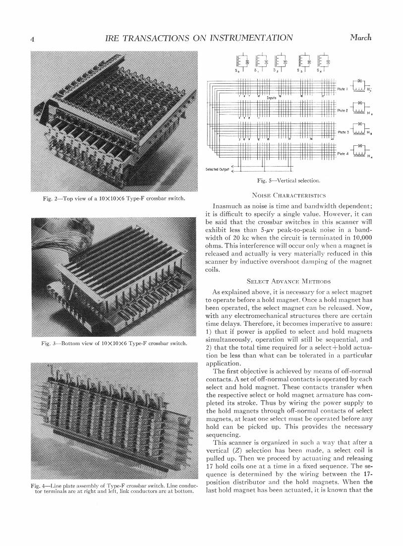
7F HE combination of these objections to existing tion of the real process, as will be shown below.systems dictated the design of a novel approach A few words need be said at this point about theemploying a comnbination of crossbar switches,' crossbar switches used in this scanner. Fig. 2 shows a
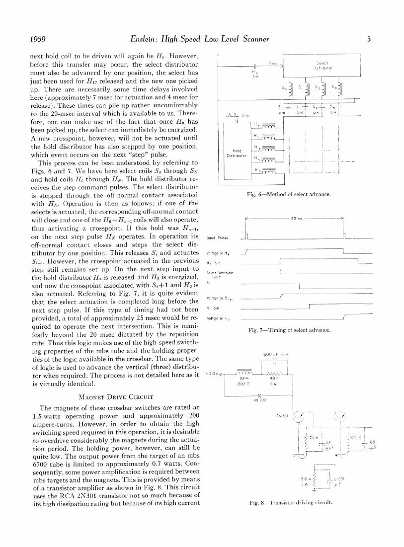
transistor circuitry, and magnetic-beam-switching top view of a 10X1OX6 Type-F crossbar switch and(mbs) tubes.2'3 Fig, 1 shows a simplified block diagram Fig. 3, a bottom view. The switch consists basically ofof the system. The system consists of two 10X10X6 10 sets of line plate assemblies; one of these is shown inType-F Cunningham crossbar switches controlled by Fig. 4. Each line plate assembly contains six line con-three Burroughs magnetic-beam-switching tube dis- ductors These line conductors run through from onetributors. Control pulses are fed to the 17-position dis- end to the other of the line plate. Ten link intersectionstributor. Every time this distributor resets to its are provided on each line plate. By actuating one inter-"home" position, it advances the 10-position distributor section it thus becomes possible to bring to a set of link
terminals (provided at the bottom of each line plate) all
Homesix of the inputs connected to such a plate. In otherwords, each line plate can be considered to be theequivalent of a 6-pole, 10-position switch with com-
Contret 10 Stage MBS pletely random access.Pulses Dmslributor
The crosspoints are actuated by means of an array of"select" and "hold" magnets. There are ten select andten hold magnets mounted at right angles to each other.
2etected 0X6 Each select magnet actuates a select tube which moves
| rcshbr Crossbar MS5 Distributor m a set of 10 interposers into 10 hold bar slots. The sub-Output '(' t a , } sequent actuation of a hold magnet then pushes on one
l l t Strain Gage t of the interposers to actuate a rocker arm which, inturn, pushes an insulating member which actuates oneof the crosspoints. Subsequently, the select used in this
Endof .3 Position <_instance can be released and the hold magnet alone willmaintain the circuit that has been set up. In this man-ner, 20 magnets are capable of actuating 100 sets of
Fig. 1-Simplified block diagram of 500-point scanner. 6-pole crosspoints. It is important to emphasize that a
select magnet must be operated before a hold magnet
by one position. Every time the 10-position distributor can have any effect. Therefore, strictly sequential opera-
resets to its home position, it advances the 3-position tion is always necessary in the use of these crossbardistributor by one. This process continues through 500 switches.control pulses. On the 501st pulse, an "end-of-scan" It is evident that since six contacts are closed every
signal is generated in the form of a contact closure, at time one of the crosspoints is actuated, some means ofthe same time that the entire scanner is returned to a selecting one out of the three pairs is desirable in thishome position. The end-of-scan closure can be used to instance in order to use a minimum amount of crossbar.interrupt the flow of control pulses. If this is not done, This vertical selection is accomplished in the followingthe scanner will resume scanning from the home posi- manner (refer to Fig. 5): the inputs are brought in pairstion. to the bottom (link) contacts of the crossbar switches,The system is thus seen to consist of a 17 (Y) by i.e., to line plates 1-3 in the typical system depicted in
10 (X) by 3 (Z) volumwe of contacts, with the mbs tubes Fig. 5. All the line conductors are then connected to-serving as address-determining counters. The "step- gether horizontally (in levels) as well as to a fourth line
plate. Operating onle of the select and hold coordinates* Manuscript received by the PGI, May 5, 1958. The work re- then brings three pairs of inputs to all four line plates.
ported here was sponsored by James Cunningham Son & Co., Inc-, Line plate 4 is then used to select one of those threeRochester, N.Y. ....
t Brooks Research, Inc.~, Rochester, N.Y. pairs. This iS done by actuating one of the three utilizedl Bulletin 55-103, James Cunningham, Son & Co., Inc., Roches- coordinates on line plate 4. Thus to select an input, one
2 "Beam Switchinlg Circuits of the MBS Tubes," Burroughs Corp., crosspoint on line plates 1-3 has to be operated as wellElectronic Tube Div., Catalog 57; 1956. a n rspito iepae4 nti anrams
3 S. Kuchinsky, "Criteria for Selection of the MBS Tube as a Cir- as on crspon on liepae4 nti anramscuit Component," Burroughs Corp., Electronic Tube Div.; 1956. complete utilization of the crossbar switches is provided.
4 IRE TRANSACTIONS ON INSTRUMENTATION March
Plate I__
- ~~~~~~~~ ~~~~~~~~~~~~plate2_ _
I I p,~~~~~teIi3 J
Se&iled Oulitpu
Fig. 5-Vertical selection.
Fig. 2-Top view of a lOXIOX6 Type-F crossbar switch. NOISE CHARACTERISTICSInasmuch as noise is time and bandwvidth dependent;
it is difficult to specify a single value. However, it canbe said that the crossbar switches in this scanner willexhibit less than 5-/Av peak-to-peak noise in a band-width of 20 kc when the circuit is terminiated in 10,000ohms. This interference will occur only when a magnet isreleased and actually is very materially reduced in thisscanner by inductive overshoot (lam)ping of the magnetCoils.
SELECT ADVANCE IMETIIODSAs explained above, it is necessary for a select miagnet
to operate before a hold magnet. Once a hold magnet hasbeen operated, the select magnet cani be released. Now,with any electromechanical structures there are certaintime delays. Therefore, it becomies imiperative to assure:1) that if power is applied to select and hold magnets
Fig. 3-Bottoni view of IOXIOX6 Type-F crossbar switch. simultaneously, operation will still be sequential, and2) that the total time required for a select+hold actua-tion be less than what can be tolerated in a particularapplication.
Te first objective is achieved by mieans of off-norm-alcontacts. A set of off-normal contacts is operated by eachselect and hold magnet. These contacts transfer whenthe respective select or hold magnet armiature has com-pleted its stroke. Thus by wiring the power supply tothe hold magnets through off-normal contacts of selectmagnets, at least one select must be operated before anyhold can be picked up. This provides the necessarysequencing.
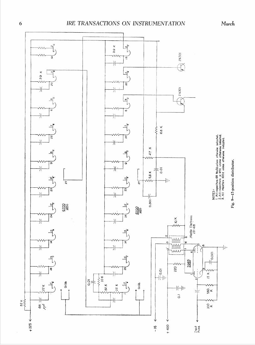
This scanner is organized in such a wav that after avertical (Z) selection has been made, a select coil ispulled up. Then we proceed by actuating and releasing17 hold coils one at a time in a fixed sequence. The se-quence is determined by the wirinig between the 17-
Fig. 4-Line plate assemiibly of Type-F crossbar switch. Line conduc- positioni distributor and the hold magnets. When thetor terminals are at right and( left, link conductors are at bottom. last hold magnet has been actuated, it is klnown that the
1959 Enslein: High-Speed Low-Level Scanner 5
next hold coil to be driveni will again be Ho. However,before this transfer may occur, the select distributor K 5tEpAJeCT
must also be advanced by one position, the select has 4njust been used for Hl17 released and the new one pickedup. There are necessarily some time delays involved I n¾4here (approximately 7 msec for actuation and 4 msec for Erelease). These tinmes can pile up rather uncomfortably iSto the 20-mnsec interval which is available to us. There- |A ee o° 5Iefore, one can make use of the fact that once H. has i___been picked up, the select can immediately be energized. HA new crosspoint, however, will not be actuated untilthe hold distributor has also stepped by one position, H
HolIdwhich event occurs on the next "step" pulse. Distributor H
This process can be best understood by referring toFigs. 6 and 7. We have here select coils So through SN Hand hold coils Ho through HN. The hold distributor re-ceives the step command pulses. The select distributoris stepped through the off-normal contact associated Fig. 6-Method of select advance.with HN. Operation is then as follows: if one of theselects is actuated, the corresponding off-normal contactwill close and one of the H0-H,1 coils will also operate, 20 ns.thus activating a crosspoint. If this hold was H,,-,,on the next step pulse HN operates. In operation its Input Pulsesoff-normal contact closes and steps the select dis-tributor by one position. This releases Si and actuates Voltage on H w
Si+,. However, the crosspoint actuated in the previous I -n
step still remaitns set up. On the next step input toS
the hold distributor H, is released and H0 is energized, Inputand now the crosspoint associated with Si+l and Ho is s' -
also actuated. Referring to Fig. 7, it is quite evident ,. _ _that the select actuation is completed long before the Voltageo S ,next step pulse. If this type of timing had not been Ii I)-n
provided, a total of approximately 25 msec would be re- Voltage on H,quired to operate the next intersection. This is mani-festly beyond the 20 msec dictated by the repetition Frate. Thus this logic makes use of the high-speed switch-inig properties of the mbs tube and the holding proper- -00 2ties of the logic available in the crossbar. The same typeof logic is used to advance the vertical (three) distribu- ___|_tor when required. The process is not detailed here as it 212 V . h_ _4 0 N/V_v_is virtually identical. 1:500T tl
MAGNET DRIVE CIRCUIT 2120HD 2120
The magnets of these crossbar switches are rated at1.5-watts operating power and approximately 200 2NM Aampere-turns. However, in order to obtain the high '-_ _ _switching speed required in this operation, it is desirable rto overdrive considerably the magnets during the actua-tion period. The holding power, however, can still be I, ' -.r1quite low. The output power from the target of an mbsC .6700 tube is limited to approximately 0.7 watts. Con- -_,_sequently, some power amplification is required between K-I--mbs targets and the magnets. This is provided by means v-e0K2C1of a transistor amplifier as shown in Fig. 8. This circuit w ruses the RCA 2N7301 transistor not so much because ofits high dissipation rating but because of its high current Fig. 8-Transistor drivTing circuit.
capability. The initial current from this transistor as This contact closure does not actually occur when thedriven by the nibs tube is approximately 0.6 amperes. last possible positioin is picked up, but eight positionsThis results in a peak currenit in the magnet coil of ap- earlier, due to the fact that this is actually a (17X1OX3)proximately 8 watts. As the 500-gf condenser charges, - 1 = 509-position scann1er. Thus the end-of-scan closurethe voltage on the coil is reduced at an exponential rate is used to actuate a relay which closes the home contactso that eventually the current flowing in the system is to the distributors and resets the scannier to the homedetermined by the series resistance of the magnet coil position. It was also shown in Fig. 6 that an off-normaland the 40-ohm resistor. At this time the current is ap- can be used for signal generation purposes to step theproximately 0.2 amperes which reduces the power dis- select distributor. The same type of operation has beensipated in the magnet coil to approximately 0.9 watts. used to step the 3-positioin distributor. In addition, theThis is well within the dissipation rating of this design. select off-normals of crossbar switch A have been usedThe circuit shown in Fig. 8 has thus the property of to activate the respective select magnets of crossbar B.
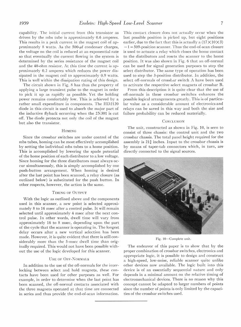
applying a large transient pulse to the magniet in order From this description it is quite clear that the use ofto pick it up as rapidly as possible. Yet the holding off-normals in these crossbar switches enhanices thepower remains comfortably low. This is achieved by a possible logical arrangemenits greatly. This is of particu-rather small expenditure in componients. The HD2120 lar value as a considerable amount of electronicsanddiode in this circuit is used to absorb the major part of relays can be saved in this way and both the size andthe inductive flyback occurring when the 2N301 is cut failure probability can be reduced materially.off. The diode protects not only the coil of the magnet CONCLUSIONbut also the transistor.
The unit, constructed as shown in Fig. 10, is seen toHOMING consist of three chassis: the control uniit and the two
Since the crossbar switches are under control of the crossbar chassis. The total panel height required for thembs tubes, homing can be most effectively accomplished assembly is 214 inches. Input to the crossbar chassis isby setting the individual nibs tubes to a home position. by means of taper-tab connectors which, in turn, areThis is accomplished by lowering the spade potential directly connected to the signal sources.of the home position of each distributor to a low voltage.Since homing for the three distributors must always oc-cur simultaneously, this is simply accomplished by onepush-button arrangement. When homing is desiredafter the last point has been scannied, a relay closure (asoutlined below) is substituted for the push button. Inother respects, however, the action is the same.
TIMING OF OUTPUT
With the logic as outlined above and the componentsused in this scanner, a new point is selected approxi-Emately 8 to 16 msec after a control pulse. It will remainselected until approxiiately 4 msec after the next con-trol pulse. In other words, dwell time will vary fromapproximately 16 to 8 msec, depending upon the partof the cycle that the scanner is operating in. The longestdelay occurs after a new vertical selection has beenmade. However, it is quite evident that there is still con- Fg 0Clilt ntsiderably more thani the 5-msec dwell time than orig- Fg 0Cmlt ntinally required. This would not have been possible with- The endeavor of this paper is to show that by theout the use of the logic developed for this scanner. proper combination of crossbar switches, electronics and
appropriate logic, it is possible to design and constructUSE OF OFF-NORMALS a high-speed, low-noise, reliable scanner quite unlike
In addition to the use of the off-normals for the inter- other devices now available. 'I'he logic built into thislocking between select and hold magnets, these conI- device is of an essentially sequential nature and onlytacts have been used for other purposes as well. For depends in a minimal amount on the relative timing ofexample, in order to determine when the last poinit has electromechanical devices. There is no reason why thisbeen scanned, the off-normal contacts associated with concept cannot be adapted to larger numbers of pointsthe three magnets operated at that time are connected since the number of points is only limited by the capaci-in series and thus provide the end-of-scani information. ties of the crossbar switches used.