Standard Specification for High-strength Steel Bolts, Classes 1 0.9 and 1 0.9.3, for Structural Steel Joints [Metric] AASHTO Designation: M 253M-OS ASTM Designation: A 490M-04a ASTM AS63M A 709M TS-4f AASHTO M 253M-05 is identical to ASTM A 490M-04a except for the following provisions: 1. All references to the ASTM standards contained in ASTM A 490M-04a, listed in the following table, shall be replaced with the corresponding AASHTO standard. Referenced Standards AASHTO M291M M270MIM270 2. Section 16.1 of ASTM A 490M-04a, change the phrase "furnish the purchaser a test report" to "furnish the purchaser a certified test report." 3. Add the following section after Section 19.1.1 of ASTM A 490M-04a as follows: "19 .1.1.1 When zinc-coated nuts are included on the same order as zinc-coated bolts, the bolts and nuts shall be shipped in the same container." 4. Replace Note 3 with the following: Note 3- ASTM F 788/F 788M and F 1470 do not guarantee 100 percent freedom from nonconforming head bursts. Sampling is designed to provide a 95 percent confidence level of freedom from nonconforming bead bursts in any test lot. Head bursts within the limits in ASTM F 788/F 788M are unsightly but do not affect mechanical properties or functional requirements of the bolt . Bolts exhibiting head bursts that do not meet the physical requirements of ASTM F 788/F 788M are rejectable. M 253M-1 MSHTO Copyright American Association ol State Highway and Transportation Otficials Provided by IHS under license with AASHTO licensee- University of Texas Revised Sub Account/5620001114 Not for Resale, 01/1112009 02:00: 02 MST No reproduction or networking permitted without license f rom IHS
Transcript
! "# $ %& ' ( ) * + , -
.
Standard Specification for
High-strength Steel Bolts, Classes 1 0.9 and 1 0.9.3, for Structural Steel Joints [Metric]
AASHTO Designation: M 253M-OS ASTM Designation: A 490M-04a
ASTM AS63M A 709M
TS-4f
AASHTO M 253M-05 is identical to ASTM A 490M-04a except for the following provisions:
1. All references to the ASTM standards contained in ASTM A 490M-04a, listed in the following table, shall be replaced with the corresponding AASHTO standard.
Referenced Standards
AASHTO M291M M270MIM270
2. Section 16.1 of ASTM A 490M-04a, change the phrase "furnish the purchaser a test report" to "furnish the purchaser a certified test report."
3. Add the following section after Section 19.1.1 of ASTM A 490M-04a as follows:
"19 .1.1.1 When zinc-coated nuts are included on the same order as zinc-coated bolts, the bolts and nuts shall be shipped in the same container."
4. Replace Note 3 with the following:
Note 3- ASTM F 788/F 788M and F 1470 do not guarantee 100 percent freedom from nonconforming head bursts. Sampling is designed to provide a 95 percent confidence level of freedom from nonconforming bead bursts in any test lot. Head bursts within the limits in ASTM F 788/F 788M are unsightly but do not affect mechanical properties or functional requirements of the bolt. Bolts exhibiting head bursts that do not meet the physical requirements of ASTM F 788/F 788M are rejectable.
M 253M-1 MSHTO Copyright American Association ol State Highway and Transportation Otficials Provided by IHS under license with AASHTO licensee- University of Texas Revised Sub Account/5620001114
Not for Resale, 01/ 1112009 02:00:02 MST No reproduction or networking permitted without license from IHS
Standard Specification for High-Strength Steel Bolts, Classes 10.9 and 1 0.9.3, for Structural Steel Joints [Metric]1
llus standard i.s inucd under the fixed designation A 490M; rhc number immediately followin~ the dc~ignmion ind.c-.uc~ the year oi uri~in.tl <h.loptiun ur. in the cuM; uf r.:vi~ivn, th-.: y~:ar u( Ja.,l rcvi!'oiun. ,\ nurnlx:r in p.m.:nlhl.'l'oC~ inJic.JIC)o the )C.Jr uf ~~~l n;appruv:.l. A ~up.;:r~cripl ~:p~ilvn (t) indicat~:, an Nitvrial dlatl).'< ~rtt.-.: tltt: l~l)l n:"i~ivn or ~:.tPI.M"oval.
TluJ standurd has bun apprmt'd for Ult' by agt!ncrt!~ of til~ Deponmt'nl of D~fenst'.
1. Scope*
1.1 This speci(ication covers two types of quenched and tempered alloy steel. metric heavy hex structural bolt~ having a tensile strength of 1040 to 1210 MPa.
1.2 These bolts arc intended for usc in structural connections comparable to those covered under the requirements of the Specification for Structural JoinL~ Using ASTM A 325 and A 490 bolts. approved by the Research Council on Structural Connections: endor ed by the American In titutc of Steel Construction and by the Industrial Fastener lnstitute.2
1.3 The bolt are furnished in nominal bolt diameters M 12 to M36. inclusive. They are designated by type denoting che mical composition as follows:
Type Oeser ption
Type 1 Type 2 Type 3
Mod um carbon alloy stool W1lhdrawn in 2002 Weathenng steel
1.4 This 'pecitic.uion is applicahle to m~tric heavy hex strut.:tur.tl bolts and alternate designs as established by the Rest:an.:h Council in its publication. Spedlication fur Structural Joints Using ASTM A 325 and A 490 holts.
1.5 For inch-pound holts, 'ee Specification A 490. 1.6 Tht: following safety hazanls caveat penains only tu the
Test Methods portion. Section 13, of this specification: This standard cloc\· nm purporl to address all of the .wifl'ly l"O/U"f' I"I M".
if any. associated with its use. It is the respmuihilil)• of the u.~er nf this sumdard 10 establish appropriate safety and health pmr1irrs nnd dNrrminr 1hr npplicnbility nf rrgulntnry limitation< prior tn 11.<('.
1 11li5 spcciticmioo is unJcr tbc jurisdiction or AST~1 Comm ittee F16 on Fa~~cnc..-n. t.mJ i ~t the din.:cl 1\::..P,Ml:r.ihilil) ur ut,:vnnniu ... 'C F16.02 Hfl Su.:cl Jlolh . 1\uu,, Rivt:l.~. wtd Wu~ltt:Q,.
Cmu.:nt cditil"~n :.'ll'l,rm·zd Aug. I. 200J. Publi .. hcd Augu!r>l 200J. Originally approvc:-d in I '!1M2. La-..t JJ(tviuus edttion a.ppro"'ctt m 20().4 as A 490M - 04.
: Avmlablc from American l n~titutc of Steel Con~tmcuon tAJSl'). Ooc E. Wad.er Dr., S1111e J IOO. t'h~eago. II 60601-2001.
2. Referenced Documents
2. 1 ASTM Sta11dardJ: 3
A 325 Specification for Structural Bolts. Steel. Heat Treated. 120/105 ksi Minimum Tensile Strength
A 490 Specification for Structural Bolts. Alloy Steel. I leal Treated. 150 ksi Minimum Tensile Strength
A 563M Specification for Carbon and Alloy Steel uts ]Metric!
A 75 1 Tes t Methods. Practices. and Tcm1inology for Chemical Analy i · of Steel Products
0 395 I Practice for Commercial Packaging E 384 Te t Method for Microindentation Hardnes of Ma-
terials E 709 Guide for Magnetic Particle Examination E 1444 Practice for Magnetic Panicle Examination F 436M Specification for Hardened Steel Washers [Metric] A 490M Specification fo r High-St renglh Steel Bo lts.
Classes 10.9 and 10.9.3, for Structural Steel Joints I Metric I F 568M Specification for Carbon and Alloy Steel Externally
Threaded Metric FaMeners [Meu·ic] F 606M l est Methods for Determi ning the Mechanical
Propen ics of Externally and Internally Threaded Fasteners, Washers. and j{jvets I Metric I
F 788/F 788M Specification for Surface Uiscont inuities of Bolls. Screws, and Studs. Inch and Metric Series
F !159M Specification for Compressible-Washer-Type Direct "lension Indicators for Use with Structural Fasteners ]Metric]
F 1470 Guide for Fastener Sampling for Specitied Mechanical P roperties and Performance inspection
F 17!1\1 Terminology for F16 Mechanical Fastt:ner G 10 1 Guide for Es timating the Atrno~pherie Corrosion
"' For rcfcrcn~o."'Cd ASTM 'LJnJ anh, vi~il 1h.: ASTM wchl\icr..t .. www.a. ... lm.t"~rg, or cuma'-'1 ASTM Cu~tumer Sc:tvile nt M:'r\'ll"eC«'~tm.ot·g. For Aunrw/ Rook of1\STU Swttdmds volume inform;:ttil,n, rclcr lo the ..,tandl\nf:!l Oocumcnl Smnm.U')' pa~c on the AS I M "'"hbtest
"A Suntmary of Chang<'S sretion a ppears at thr rnd of this stondard.
Copyri!7l1 CASTM l.ntClm.t1JOO.al. 100 Barr Harbor Drwo, PO Box C700, Wast Conshohockon PA 1D428·2QSQ, Unhoc Statos
TS-4f Copyright American Associalion of State Highway and Transportalion Officials Provided by IHS under license with AASHTO No reproduction or networking permitted without license from IHS
M 253M-2
Ucensee .. university of Texas Revised Sub Accountl5620001114 Not fOf Resale, 01/1 1/2009 02:00:02 MST
AASHTO
• A490M-04a
TABLE 1 Chemical Requirements for Type 1 Bolts
Element
Carbon For sizes through M30 For size M36
Phosphorus. max Sulfur, max
Heat Analysis, %
0.3(H)48 0.35-{) 53 0.040 0.040
Product Analysis.%
o.2a-c.so 0.33-c.SS 0.045 0.045
Alloying Elements -+See 6 1 ...
TABLE 2 Chemical Requirements for Type 3 Bolts
Elomcnt Hoal Analysis, %
Carbon Sizes M20 and smaller 0.2o-o.53 Sizes larger than M20. 0.3()-{).53
Manganese, min 0.40 Phosphorus, max 0.035 Sulfur, max 0.040 Copper 0.2o-o.60 Chromium. min 0.45 Nickel, min 020 or Molybdenum, min 0.15
Resistance of Low-A !loy Steels 2.2 ASMt: Standards:" B I . 13M Metric Screw Threads
Product Analysis, 'l'o
0 19-c.SS 0.28-c.SS
0.37 0.040 0.0~
0. 17...C.63 0.42 Ot7
O. t4
B 18.2.3.7M Metric Heavy Hex Structural Bolts B 18.24. 1 Pan Identi fying Number (PI ) Code System 2.3 ISO Standardv:" 74 12 Hexagon Bolts for High Strength Structural
Bolting With L•u·ge Width Across Flats (Short Thread Length)-Product Grade C-Property Classes 8.8 and 10.9
2.4 SA£ Standards~: J 121 Decarburization in Hardened and Tempered Threaded
Fasteners
3. Tcrmiuolog_v
3. 1 Terms med in th i ~ specification are defi ned in Terminology F 1789. unless otherwise defined herein.
4. Ordering Information
4.1 Orders for bolts under this specification shaU include the following (sec Note 1):
4.1.1 Quantity (number of pieces of bolts and accessories); 4. 1.2 Size, incl uding nominal bolt diameter, thread pitch,
and bolt length; 4. 1.3 Name of product: metric heavy hex tructural bolts; 4. 1.4 Type of bolt (Type I or 3). When type i not specified.
either Type I or Type 3 shall be furnished at the supplier's option:
4.1.5 ASTM designation and year of issue; 4.1.6 Other components such as nuts, washers. and washer
type direct ren ion indicators, if required;
• Available from American StX·icty of Mechanical Engineers fASME), ASME Interna tional He.tdqu:trtt'Oi, Three P.trk Ave., rew York, r\Y 10016-5990 .
. ~ Available from Society of Automotive Enginttrlrl (SAE). 400 Commonwcahh Dr .. Warrendale, PA 15096-nooJ.
TS-4f Copyright American Association of State Highway and Transponation Officials Provided by IHS under license with AASHTO No reproduction or networking permitted without license from IHS
M 253M-3
4.1.7 Cenification. if required ( ee Section 16): and 4.1.8 Special requ irements, if required. 4.1.9 f'or establishment of a part identifying system, see
ASME 131 8.24. 1.
NoTF. I A typical ordering description follows: 1000 pieces M24 x 3 X 10(1 mm lnng, heavy hex structurul holt, Type I , ASTM A .J9() M- 03: each with two hardened wa.,hers. ASTM r 436M. Type I. and one heavy hex nut, ASTM A 563M. Gmdc DH.
4.2 Recommended Nuts 4.2. 1 Nuts conforming to the requirements of pecification
A 563M are the recommended nuts for use with Speci fication A 490M heavy hex structural bolts. The nms shaU be of the class and have a surface finish for each type of bolt as follows.
Bolt Type and Anlsh Nut Class and Finish
t , plain (uncoated) 3, weather1ng steel
A 563M-10S, 10S3, pain (uncoated) A 563M-1 053, weathering steel
4.3 Recommended Washers 4.3. 1 Washers conforming to Specification F 436M are the
recommended washers J'ur use with Specilic;atiun F 490M heavy hex >lruc; tur.tl bull~. The wa~hc:n. shall have a >Urfaco:: lini h rur each type or bolt a:. follows.
Bolt Type and Fin sh
1, plain (uncoated) 3, weathering steel
4.4 Other Accessories
Washer F01lsh
plain (uncoatea) weatnenng steel
4.4.1 When compressible washer type tension indicators are pccificd to be used with these bolts, they ·hall conform to
Specification F 959M, Type 10.9.
5. Materials and Manufactu re
5.1 Neat 'li"ewment-Type I and Type 3 bolts shall be heat treated by quenching in oil from the austenitic temperature and then tempered by reheating to a temperature of not les than 425°C.
5.2 11lreading- 'l'he threads shall be cut or rolled. 5.3 Protective Coatings-The bolts hall nol be coatcdh by
hot-dip zinc coating. mechanical deposition, or electroplating with Line or other metallic coatings.
6. Chemical Composition
6.1 Type I bolts shall be alloy steel conforming to the chemical compo ition requirements in Table I. The steel shall contain sufficient alloying elements to qual ify it as an alloy steel (sec Note 2).
O'ffi 2-Steel is considered to be alloy, by the American Iron and Steel ln>titmc, when the maximum of the range given for the content of alloying c lc1ncnts e xceed"' one 11r more nf the following limits: manganese. l .fl.li) ~; silicon. 0.60 %: copper. 0.60 %: or in which a deli nile range or a delinite minimum quantity of any of the foUowing clcmems is specified or required within I he limit, of the recognized field of con•tnrctional alloy steels: aluminum, chromium up to 3.99 %, cobalt. columbium, molybdenum. nickel. titanium. tungsten. vnnndium. zirconium. or any other alloying elements added to oblain a desired alloying etTecL
tt F11r mure dt'tail ~ lht> H. E. Tmvn~nd R~pon •·erret:L\ ~,r Zinc Coating 'i on Slic:.\s Couosion Cracki ng ..and Hydroge n Embt iulement or Low Alloy Steel," published in Metallurgical TranQction~. Vol. 6, April 1975.
licensee=University of Texas Revised Sub AccounV5620001 I 14 Not for Resale, 01/1112009 02:00:02 MST
MSHTO
• A490M-04a
6.2 Type 3 bolt shall be weathering steel confom1ing to the chemical composition requirements in Table 2. See Guide G I 0 I fur methods of estimating the atmospheric corrosion resistance or low a lloy steel.
6.3 Produc t analyses made on finished bolts representing each lot shall conform to the product analysis requirements specified in Table I or Table 2. as applicable.
6.4 Applications of heats of steel to which bismuth, e lenium, tellurium, or lead has been intentionally added ·hall not be permitted for bolts. Compliance with this requiremelll shall he ha.~cd on a statemenl on the steel certificate indicating thut these eleme nt.s were not intent ionally added.
6.5 C hemical analy e hall be performed in accordance with Te. t Method., Practice . and Terminology A 751 .
7. Mechanical Properties
7 . I Hardness The bolts shall t.:unfurm tu the han.lne~s specified in Table J.
7.2 Te~1siiP PmpPrriPs:
7.2.1 Except as permitted in 7.2.2 for long bolts and 7.2.3 for short bolts. nominal bolt diameters M24 and smaller having a length of 2'!. D and longer, and nominal bolt diameters larger than M24 having a length of 3D and longer ·hall be wedge tested full size and shall confom1 to the minimum wedge te nsile load. and proof load or alternative proof load specified in Table 4. The luatl at.:hievetl during proof load tes ting shall be equal to or g reater than the specified proof load.
7 .2.2 When the length of the bolt makes full-si7.e testing imprnct ical, machined specimens shall be tested and shall conform to the requirements specified in Table 5. When bolt are tested by both fu ll-size and machined specimen methods. the full-size test shall take precedence.
7.2.3 Nominal bolt diameter · M24 and smaller havi ng a le ngth shorter than 2 1/.1 /J down to 2 /J inclusive, which can not be wedge tensik tested shall be axial ly ten~ruu test~d fu ll ~ize and ~ha ll conform to the minimum tensile load and pronf load or alternate proof load ~peeified in Table 4. orninal bolt diameter. M24 and smaller ha,•ing a length shorter than 2D which cannot be axially tensile tested shall be qualified on the basis of hardness.
7 .2.4 For bolts on wh ich both hardness and tension tests are performed. accepta nce ba5ed on tensile requirement sha ll lake precedence in the event of low hardness readings.
TABLE 3 Hardness Requirements for Bolt Sizes M12 to M36 Inclusive
Nommal Bolt Bnnel ocl<well c Diameter, mm
Lenglh" min max mn max
M12to M24, Less than 20 3 11 352 33 39 1nclusive ?0 and longer 35? 39 Ovor M24 to M36, Less than 30 3 1t 352 33 39 inclusive 30 and longer 352 39
" Heavy hex structural bolts M24 and smaller and shorter I han 20 are subject only to minimum and mwomum hardness Heavy hex s:ructural bolts larger than M24 to M36 inctusive and shorter than 30 are subject only to minimum and maximum hardness.
TS-4f Copyright American Association of State Highway and Transponation Officials Provided by IHS under license with AASHTO No reproduction or networking permitted without license from IHS
M 253M-4
8. Carburization!Decarburization
ll. l Definition- This test is intended to evaluate the presence or absence uf carburitation and decarburiwtion a determi ned by the difference in microhardness near the surface and core.
8.2 Requirement.\: 8.2.1 Carburization-The bulls shall ~huw nu evidence uf a
carburit.cd surface when evaluated in atxurdam;e with the hardness methods established in SAE 1 12 1.
8.2.2 Decarburi:.ation- Hardness value di lrerences shall nut exceed the requirement~ set forth fur decarburiatiun in SAE 11 21 fur Cla~s 2/3H materia ls .
8 .3 Pmccdurc- Te~ting fur carburizatiun/decarburiLatiun shall be pe rformed in accordance wi th the microhardness (referee) methods established in SAE J 121.
9. Dimensions
9.1 Head and Body: 9. 1.1 The bolts shall conform to the di mensions for heavy
hex structural bolts specified in ASME BI8.2.3.7M for nominal bolt diameter Ml6 to M36 inclusive and ISO 74 12 for size M l 2.
9.2 Tltreads: 9.2. I Threads shall Metric Coarse Thread Series as specified
in ASME B I.! 3M, and shall have Grade 6g tolerance. 9.2.2 The thread length shall not be changed from that
specified for heavy hex structuml bolts in AS ME 13 18.:2.3.71\1 and ISO 74 12 in 9.1. 1. Bolts requiring thread lengths other than those required by this specification hall be ordered under Specification r 568M, Class 10.9 and 10.9.3.
10. Workmanship
I 0. 1 The allowable limit~. inspet.:tiun, and t:valuatiun uf the urface di ·continuitit:s. lJUench cracks, forging t;rack~. head
bursts, 'hear bursts, ~ams, folds, th read laps. voids. tool marks, nids. anti gouges shall be in at:curdancc with Spccifi cation F 788/F 788M (see utc 3).
N= 3- Specilicat ion F 7H81F 788M and Guide F 1470 do not guara ntee 100 % freedom from head bursL•. Sa mpling is designed to provide a 95 % confidence Je,el of freedom from head bursts in any te>t lot. Head bursts. within the limits of Speci fication F 788/F 788M, arc unsighlly but du nut afTccl lllcc hani""l prupcnic' ur functiunal ft:4uirt:n1c111< uf I he bult.
11. Magnetic Pa rticle Inspection l'or LongitudiJtal Uisconlinuitil'S and Tr-ansverse Cracks
11.1 Requiremems: I I . 1. 1 Each sample represe ntative of the lot shall be rrutg
netic pnnicle inspected for longirudinnl discontinuities nnd transvcr c crack .
11. 1.2 The lot, a repre. cmcd by the ample, hall be free from nonconforming bolts. as defined in 11.3_ when inspected in accordance with 11.2- 11.2.4.
11.2 lnspeclion Pl'()cedure: 11.2 .1 The in pcction sample shall be selected at random
from each lot in accordance with Table 6 and examined for longitudinal di. continuities and tran. verse crncks.
11.2.2 Magnetic particle inspection shall be conducted in a cordancc with Guide E 709 or Practice E 1444. Guide E 709 hall be used for referee purpose . Tf any nonconforming bolt
licensee=University of Texas Revised Sub AccounV5620001 114 Not for Resale, 01/ 1112009 02:00:02 MST
MSHTO
• A490M-04a
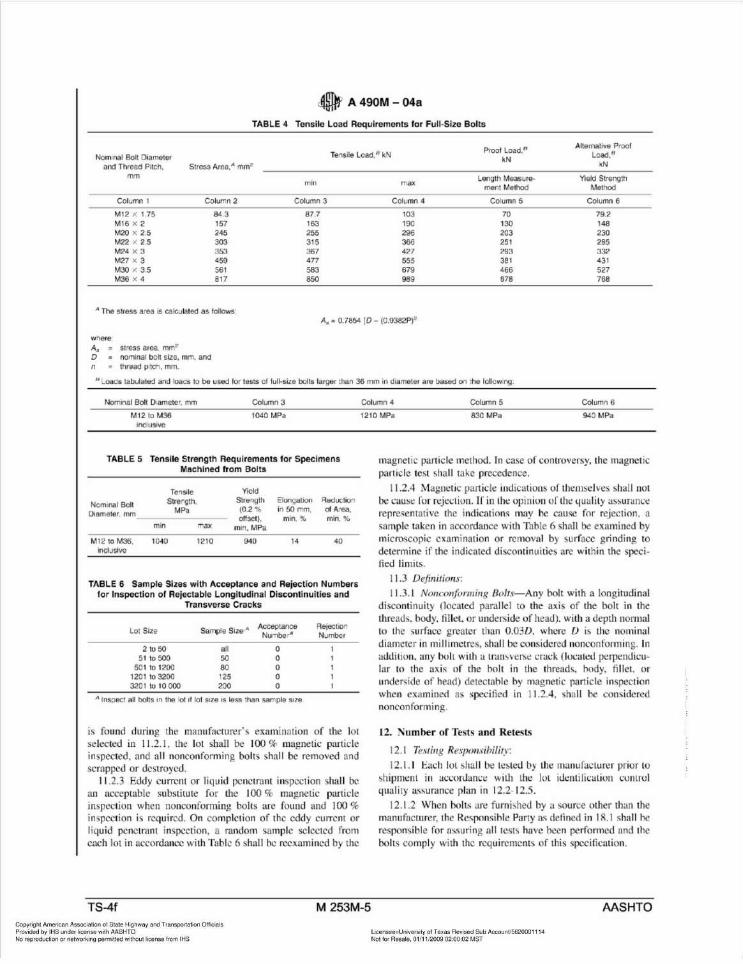
TABLE 4 Tensile Load Requirements for Full-Size Bolts
Alternative Proof
Nom•nal Bolt Diameter and Thread Pnch,
mm
Tensile Load, n kN Proof Load, 8
Load," kN
Column I
M12 X 1.75 M16 X 2 M20 X 2 5 M22 X 2 5 M24 X 3 M27 X 3 M30 X 3.5 M36 X 4
01ameter. mm MPa (0.2 % in SO mm, of A"ea. offset), min, % min,%
min max min, MPa
M 12 to M36, 1040 1210 940 14 40 Inclusive
TABLE 6 Sample Sizes with Acceptance and Rejection Numbers for Inspection of Rejectable Longitudinal Discontinuit ies and
Transverse Cracks
Lo1 Size
2 to 50 51 to 500
501 to 1200 1201 to 3200 320 1 to 10 000
all 50 80 125 200
Acceptance Number'
0 0 0 0 0
A Inspect all bolts 1n the tot 1f lot SIZe IS less than sample stze.
Rejection Number
is found during the maoufncrurer' s examination of the lot selected in 11.2.1 . the lot shall be 100 % magnetic pan icle inspected, and all nonconforming bolts shall be removed and scrapped or de troycd.
11 .2.3 Eddy current or liquid penetrant inspection hall be an acceptable substitute for the I 00 % magnetic part icle inspection when oonconfom1ing bolts are found and I 00 % in pcction is required. On completion of the eddy current or liquid penetrant inspection, a random sample selected from each lot in accordance with Table 6 shall be reexamined by the
Column 4 Column 5 Column 6
12 10 MPa 830 MPa 940 MPa
magnetic particle method. In case of controversy, the magnetic part icle test hall take precedence.
11.2.4 Magnetic pru1icle indications of them ·elves shall not bt: caust: for rejeclion. If in lht: opinion of the 4ualil}' as~uranco:: representative the indications may he cause for rejection, a . ample taken in accordrutce with Table 6 hall be examined by microscopic examination or removal by surface grinding to determine if the indicated discontinuities are within the specified limits.
11.3 Definitions:
11.3. 1 Nonconforming Bolrs- Any bolt wilh a longitudinal discontinuity (located parallel to the axis of the bolt in the threads. body. fillet, or underside of head). with a depth normal to the surface greater than 0.030. where D is the nominal diameter in mi ll imetres, shall be considered nonconforming. In addilion. any bolt with a lmn vt:rst: crack (IOl:aled pt:rpendicular to the axis of rhe holt in the threads, hody. fi llet. or under ide of head) detectable by magnetic panicle inspection when examined as specified in 11.2.4. shall be considered nonconformi ng.
12- Number of Tests and Retests
12. 1 Te.1ting Re~ponl·ibifity:
12.1.1 Each IOL hall be rested by the manufacturer prior 10
>hipmenl in acconlam:(: with the lot idenli lication comrol quali ty assurance plan in 12 .2- 12.5.
12 .1.2 When bolls are furni!.hed by a source other rhan the manufacturer, the Re~ponsihle Parry as defi ned in 1 R.l shall he re ponsible for assuring all test have been performed and the bolts comply with the requirements of this specification.
TS-4f M 253M-5 MSHTO Copyright American Association of State Hig hway and Transponation Officials Provided by IHS under license w ith AASHTO No reproduction or networking permitted w ithout license from IH S
licensee=University of Texas Revised Sub AccounV5620001114 Not for Resale, 01/ 1112009 02 :00 :02 MST
• A490M-04a
12.2 Purpo ·e of Lot Inspection-The purpose of a lot inspection program shall be to ensure that each lot as represented by the samples tested conforms to the requirements of thi specification. For such a plan to be fully effecti ve, it is es entia t that secondary processors. di tributo1 . and purchase rs mai ntain the identification and integr ity of each lot unti l the product is installed .
12.3 Lot Metltod-i\ll bolts shall be proccs ed in accordance with a lot identification-control qual ity assurance plan. llte manufacturer, secondary proce~ or~. and disu ibutors hall i1.lt:ntify and maintain the integrity of ea~:h lot of boiL~ from raw-material selection through all processing operations and treatments to final packing and shipment. Each lot -;hall he assigned its own lot-identification number, each lor ~hall he tested, and the in pP-<:tion test repom for each lot shall he retained.
12.4 Lot Dejinitio11: 12.4.1 Standard Lm- A lot shall be a quantity o f uniquely
identified heavy hex structuml bolts of the ~ame nominal bolt diameter and length produced con ecutively at the initial operation from a si ngle mill heat of material and proces ed at o ne time, by the same proce s, in the same manner. so that statistical . ampling i. valid. "llte iuentity of the lot and lot integrity sha ll be maintained throughout all subsequent operation ;md packaging.
12.5 Namber of Tests:
12.5.1 The minimum number of tests from each lot for the tests specified below shall be as follow : lesls Number ot Tests '" Accordance With
Hardness. tensile strength, prool load Guide F 1470 Surtace discontinuities Speci'ICation F 788/F 768M Magnetic particle insoection Table 6 Dimensions and threao l it ASME Bt8.2.3.7M and ASME Bl. \3M
12.5.2 f'or carburizat ion and decarburization tests, not less than one sample unit per manufactured lot shall be tested for microhardness.
13. Test Methods
13. 1 Tensile, Proof Load, and Hardness:
13. 1. 1 Tensile, proof load. and hardness test hall be conducted in accordance with Te t Methods F 606M.
13.1.2 Ten ile strength shall be determi ned u ing the Wedge or A)(ial Ten ion Testing Method of Full Size Product Method or the Machined Test Specimens Method. depending on size and length as specified in 7 .2. 1-7.2.4. Fracture on full-size tests shall be in the body or threads of the bolt without a fracture at the junction of the head and body.
13.1.3 Proof load shall be determined using Method I, Length Mea urement. or Method 2, Yie ld Strength, at the option of the manufacturer.
13.2 Carburi:ation/Decarburization-Tests hall be conducted in accordance with SAE 11 2 1 Hardness Method.
13.3 Microflard11ess-Te t. hall be conducted in accordance with Test Method E 384.
13.4 Magnetic Particle-In pcction hall be conducted in accordance with ection I I.
14. Inspection
14.1 If the inspection desctibcd in 14.2 is required by the purcha ·cr. it shall be pecilied in the inquiry anu contrac t or order.
14.2 The purcha er's representa ti •e shall have free entry to all parts of manufacturer's works or . upplier's place of bu~ines~ that ~un~cm the manu ra~turc of the material orucrcd. T he manufa~:t urcr or suppl ier hall alTurd tht: purd1as~:1 ' representative all rea ·unable faci li ties to satisfy him that the material is being furnished in accoruance wi th this ~pe ilication. All tc~ts anu i n~pections requir~u by the spcdlicatiun that are rt:l.jUeStCd by the purt:ha~cr' b rcprt:~t:ntativ~ >hall bt: maU<! before ~hipment. anu shall be ~unuucted a~ not to inte rfere unne~:es ari ly with the oper.ttion of the manufacturer' · work or ~upplier's place of hu~i nebs.
15. Rejection and Rehearing
15. 1 Disposition of nonconforming bolts ·hall be in accordance with the section ti tled ··Disposition of onconforming LotS·· in Guide F 1470
16. Certification
16.1 When specified on the purchase order. the manufacturer or supplier. whichever is the responsible party as defined in Section 17, hall furnish the purchaser a te t report that inc ludes the following:
16. 1. 1 Heat analysis. heat number. and a tatement certifying that heats havi ng bismuth. selenium, tellurium. or lead intentionally added were not used to produce the bolts:
16.1.2 Re ults of harunes , ten ilc, and proof load tc ts: 16. 1.3 Results of magnetic particle in pection for longitu
dinal discontinuitie and tran ver e cracks; 16.1.4 Results of tests and inspections for surface di. conti
nuitie · including visual inspection for head bursts: 16. 1.5 Re ults of carburization and decarburization tests; 16. 1.6 Statement o f compliance wi th dimensional and
thread fit requirements; 16. 1.7 Lot number and purch<c e order number; 16.1.8 Comple te mail ing addre s of responsible party: and 16.1.9 Title and signature of the individual a signed certi-
fication re ponsibility by the company officer . 16.2 Failure to include all the required information on the
test report shall be cause for rejection.
17. R esponslhlllty
17.1 The party respon ible for the fa tener shall be the organization that upplies the fa tener to the purchaser.
18. Product Marking
l8.1 Mttlll({i:tcltlrer 's ldellt(ficatiun-All Type l and Type 3 bolts hall be marked by the manufacturer with a unique identifier to identify the manufacturer or private label distributor. a appropriate .
18.2 Grade ldelltification: 18.2.1 Type I bolts hall be marked "A 490M." 18.2.2 Type 3 bolts hall be marked ''A 490M" underlined.
The u c of additional distinguishing mark to ind icate the bolt are weathering steel ha ll be at the manufacturer' option.
TS-4f M 253M-6 MSHTO Copyright American Associat ion of State Highway and Transportation Officials Provided by tHS under license with AASHTO No reproduction or networking permitted without license from IHS
licensee=University of Texas Revised Sub AccounV5620001114 Not for Resale, 01/1112009 02:00 :02 MST


![Series GW control valves - SMS TORK...Valve Travel [%] 10 20 30 40 50 60 70 80 90 100 FL 0.9 0.9 0.9 0.9 0.9 0.9 0.9 0.9 0.9 0.9 Valve Size Orifice Dia. Travel Rated Cv Inch mm Sign](https://static.documents.pub/doc/80x56/5f4fb482064cf52aed0d638f/series-gw-control-valves-sms-tork-valve-travel-10-20-30-40-50-60-70-80.jpg)


