PROCEEDINGS, Twenty-Ninth Workshop on Geothermal Reservoir Engineering Stanford University, Stanford, California, January 26-28, 2004 SGP-TR-175 HIGH TEMPERATURE DOWNHOLE RESERVOIR MONITORING SYSTEM Joseph A. Henfling Randy A. Normann Sandia National Laboratories P.O. Box 5800 Albuquerque, NM, 87185, USA e-mail: [email protected]ABSTRACT Sandia has developed a downhole monitoring system that can operate continuously at temperatures up to 240°C. The developed monitoring system can be used to measure small changing reservoir conditions, thereby providing information on the condition of the Geothermal reservoir. This information can help engineers develop strategies to extend the life of Geothermal reservoirs. The monitoring system utilizes SOI (Silicon-on-Insulator) technology, which is known for its inherent reliability at elevated temperatures. The present monitoring system measures wellbore temperatures and pressures but other sensors such as accelerometers and strain-gage type sensors could easily be added. By utilizing a precision quartz pressure sensor such as the Quartzdyne pressure sensor, pressure changes less than .008 psi and temperature changes less than .008°C can be made. This capability enables the monitoring system to detect earth tidal pressure effects and earthquake-induced pressure changes. To date, three systems have been successfully deployed. INTRODUCTION Unshielded electronic control and measurement systems that can operate for many years at 300°C (580°F) are technically achievable. High temperature (HT) semiconductor technology has reached the point of operating at these temperatures. However, making this technology commercially viable is more difficult. Over the past few years, Sandia has been helping to establish newly initiated high temperature electronic product lines that meet the requirements of the geothermal industry. The development of high temperature electronics and sensors can facilitate the advancement of all aspects of geothermal power production--from futuristic power plant controls, which can look down into production and re-injection wells for control data, to drilling and logging tools with nearly indefinite life inside the well. Two of the shortcomings that prevented the development of a practical dewarless tool were the lack of SOI (silicon-on-insulator) devices that would interface to large memory for both program and data storage and a bootstrap program that would ease the implementation of user developed software. Sandia has subsequently designed and built a device to solve both of these issues, enabling a high temperature Dewarless (non-flasked) tool to become a reality. Advancements in sensors and batteries also aided in our ability to design a viable Dewarless tool. Clearly, high temperature electronics is an enabling technology in all aspects of future geothermal developments. However, one of the first and most important applications of high temperature electronics will be tools designed to help keep geothermal power plants on-line. At the last World Geothermal Congress, it was reported that the US lost 500MW of geothermal power production capacity since the last Congress! [3] High temperature tools can impact this trend almost immediately by giving operators the ability to monitor reservoir characteristics on a much more frequent basis, or in the case of a downhole reservoir monitoring system, continual real-time data is achieved. This is the area in which new tools will immediately benefit the industry through improvements in production, re- injection and well maintenance strategies. Based on SOI technology, Sandia has developed and field-tested a PT (Pressure/Temperature) logging tool and three reservoir monitoring tools. After a brief discussion on Sandia’s approach to high temperature electronics, the remainder of this paper will elaborate on the high temperature downhole reservoir monitoring system. APPROACH The Sandia approach is simple: “Adapt and expand high temperature electronics technology to downhole applications”. The aircraft industry has been the
Transcript
PROCEEDINGS, Twenty-Ninth Workshop on Geothermal Reservoir Engineering Stanford University, Stanford, California, January 26-28, 2004 SGP-TR-175
HIGH TEMPERATURE DOWNHOLE RESERVOIR MONITORING SYSTEM
Sandia has developed a downhole monitoring system that can operate continuously at temperatures up to 240°C. The developed monitoring system can be used to measure small changing reservoir conditions, thereby providing information on the condition of the Geothermal reservoir. This information can help engineers develop strategies to extend the life of Geothermal reservoirs. The monitoring system utilizes SOI (Silicon-on-Insulator) technology, which is known for its inherent reliability at elevated temperatures. The present monitoring system measures wellbore temperatures and pressures but other sensors such as accelerometers and strain-gage type sensors could easily be added. By utilizing a precision quartz pressure sensor such as the Quartzdyne pressure sensor, pressure changes less than .008 psi and temperature changes less than .008°C can be made. This capability enables the monitoring system to detect earth tidal pressure effects and earthquake-induced pressure changes. To date, three systems have been successfully deployed.
INTRODUCTION
Unshielded electronic control and measurement systems that can operate for many years at 300°C (580°F) are technically achievable. High temperature (HT) semiconductor technology has reached the point of operating at these temperatures. However, making this technology commercially viable is more difficult. Over the past few years, Sandia has been helping to establish newly initiated high temperature electronic product lines that meet the requirements of the geothermal industry. The development of high temperature electronics and sensors can facilitate the advancement of all aspects of geothermal power production--from futuristic power plant controls, which can look down into production and re-injection wells for control data, to drilling and logging tools with nearly indefinite life inside the well.
Two of the shortcomings that prevented the development of a practical dewarless tool were the lack of SOI (silicon-on-insulator) devices that would interface to large memory for both program and data storage and a bootstrap program that would ease the implementation of user developed software. Sandia has subsequently designed and built a device to solve both of these issues, enabling a high temperature Dewarless (non-flasked) tool to become a reality. Advancements in sensors and batteries also aided in our ability to design a viable Dewarless tool. Clearly, high temperature electronics is an enabling technology in all aspects of future geothermal developments. However, one of the first and most important applications of high temperature electronics will be tools designed to help keep geothermal power plants on-line. At the last World Geothermal Congress, it was reported that the US lost 500MW of geothermal power production capacity since the last Congress! [3] High temperature tools can impact this trend almost immediately by giving operators the ability to monitor reservoir characteristics on a much more frequent basis, or in the case of a downhole reservoir monitoring system, continual real-time data is achieved. This is the area in which new tools will immediately benefit the industry through improvements in production, re-injection and well maintenance strategies. Based on SOI technology, Sandia has developed and field-tested a PT (Pressure/Temperature) logging tool and three reservoir monitoring tools. After a brief discussion on Sandia’s approach to high temperature electronics, the remainder of this paper will elaborate on the high temperature downhole reservoir monitoring system.
APPROACH
The Sandia approach is simple: “Adapt and expand high temperature electronics technology to downhole applications”. The aircraft industry has been the
2
driving force for the commercial production of SOI circuits. The aircraft industry needs high temperature electronic engine controllers. The components needed for electronic engine controllers are nearly identical to the components needed for a simple logging tool. Most geothermal applications will require features and components not required for aircraft. For example, special batteries and narrow tubular packaging must be developed for unshielded geothermal logging tools [1]. Once new high temperature designs are demonstrated for geothermal wellbore applications, the geothermal industry will gain never-before-realized instrumentation capabilities that will lead to new approaches in well logging and reservoir characterization. Sandia realizes that many factors are stifling the development of a high temperature tool by the geothermal service companies. Some of these factors include:1) SOI devices to complete the SOI component set available from Honeywell; 2) a means to reduce the learning curve required to develop a downhole tool; 3) identifying and testing components and sensors needed to build a complete system; 4) development of high temperature (250-300°C) batteries[2]; and 5) fabrication issues such as the development of better solders and fluxes. Sandia has been working to solve the above issues, and has designed a custom ASIC (Application Specific Integrated Circuit) to complement the SOI components available from Honeywell. We have designed and assembled “learning kits” to decrease the development time of designing tools. We have an ongoing testing and evaluation program to identify and qualify suitable high temperature components and sensors. Sandia is currently working on developing a high temperature battery and better solders and fluxes. Geothermal service companies can utilize the work Sandia is providing to the industry, which will result in reduced cost to develop high temperature Dewarless tools that were not possible even a short time ago.
Results Sandia has made several advancements in the past few years to promote the high temperature electronics industry and to encourage geothermal service companies to utilize these advancements to design their own high temperature tools [4]. Details of our accomplishments follows:
Sandia-designed SOI interface device Two of the shortcomings that prevented the development of a practical downhole logging tool were the lack of SOI devices that would interface to large memory and a bootstrap program that would
ease the implementation of user developed software. Sandia overcame this obstacle by designing a custom ASIC that performed the above functions along with many additional attributes. The ASIC design was then fabricated at Honeywell using their SOI technology. Sandia has given Honeywell permission to make this SOI device commercially available. The part number for this device is HT83SNL00. The HT83SNL00’s features are summarized below: • Interface the HT83C51 microprocessor to
500Kbytes of HT (High Temperature) memory • Interface to 48 analog signals (i.e. 48 arm casing
inspection tool) • Interface to 3 highly accurate frequency sensors
(i.e. Quartzdyne pressure sensor) • Interface to a directional spinner (i.e. for a
Pressure/Temperature/Spinner tool) • Basic logging program built in (similar to
booting up a PC) • Ability to communicate directly with additional
HT83SNL00 based systems • Watch-dog timer to enable the orderly recovery
of a user program that is not functioning properly • Interface to 9 general purpose counters • Programmable clock outputs • Interface to serial devices • Eight pins that are bit wise programmable Upon delivery of the HT83SNL00, Sandia initiated an extensive evaluation of the device. This work was completed in June of 2001 and all functions were verified to be operating as they were designed. By August of 2001, the first oven tests were completed. The completion of this milestone confirmed that the device would operate at temperatures up to 250°C. Although we expect the device to be capable of sustained operation to 300°C, we currently do not have a suitable test fixture needed to verify this attribute. In September of 2001, preliminary information on the HT83SNL00 was made available to the industry.
HT Chipset learning kit One of our major goals was to "advertise" and conduct additional testing of the high temperature logging tool. In order to generate interest and encourage private companies to develop high temperature tools, we have released a complete set of program examples and learning hardware. With these aids, even small companies supporting the geothermal industry can quickly start developing high temperature tools. The learning kits contain:
• A low temperature electronic test fixture for learning the capabilities/functions of the
3
high temperature chipset currently available (including the HT83SNL00).
• Software to interface the test fixture to the PC
Prototype Pressure/Temperature (PT) Tool With the addition of the HT83SNL00, we were able to design and build a prototype PT tool capable of sustained operation at 250°C. This tool was designed as a wireline tool that transmits the downhole data to the surface every 3 seconds. It acquired not only the wellbore pressure and temperature but also 8 additional analog measurements and two frequency measurements. The electronic design includes the capability of adding additional sensors such as a spinner, when they are desired. By November of 2001, this PT tool was built, oven tested and was ready for field deployment. The tool was used to successfully log three geothermal wells ranging in temperature from 204 to 240°C. It was deployed on a 15000 foot, high temperature wireline. In each case, the tool remained downhole for 30 to 40 hours. When we returned from the field tests, additional long-term oven tests were initiated to help establish a baseline for determining tool life at sustained high temperatures. The tool was placed in an oven for approximately 1200 hours at 225°C and more than 600 hours at 250°C. It operated successfully for this test and is still a functioning tool. (Other obligations on the oven limited the length of this test.) This is an accomplishment that would not have been possible without the utilization of the SOI technology. A natural progression from the PT Tool was the reservoir monitoring system. This type of system has many benefits. For example, the data in itself is important, and additionally, the system is a test bed for newly developed high temperature sensors and is a testimonial for the reliability of tools designed with SOI components.
RESERVOIR MONITORING SYSTEM
To date, three reservoir monitoring systems have been successfully deployed. The first two systems were funded by the USGS to help in their work in reliably predicting volcanic unrest. Several examples of pre-eruptive groundwater pressure changes show that fluid pressure monitoring can be a valuable tool for detecting volcanic unrest. Subsurface magma movement affects fluid pressure by deforming the earth's crust and heating subsurface fluids. Moreover, intriguing interactions between earthquakes and volcanic unrest are believed to be mediated by fluid-pressure effects. By monitoring
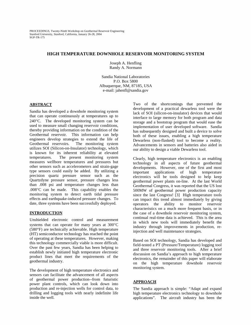
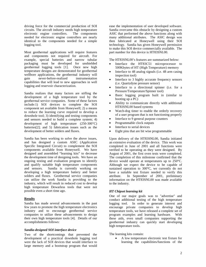
downhole pressure and temperature with very high resolution, and interpreting the resulting data in the context of crustal deformation, seismicity, and gas emission, valuable volcanic information may be gained from these tools. The two systems are currently installed in moderate temperature wells located near Mammoth Lakes, CA. One of these tools will be redeployed this summer in a moderate temperature well located in Hawaii. The third system was funded by the Department of Energy’s National Energy Technology Laboratory, NETL, and is deployed in a Coso Naval Test Range well located only a mile away from the Coso Geothermal power plant. Fluctuation in the pressure/temperature can be analyzed by Navy Geologists to learn more about the reservoir. The tool has been installed within the well at 3100 ft using wire in tubing. At this point the nominal temperature is 192°C (379°F). This is the hottest location within the well. Prior to the tool going into the well, the tool was oven tested for one month at temperatures between 180 and 200°C. The purpose of this field test is to demonstrate the increased reliability gained when using manufacturer-qualified high-temperature electronic components. Sandia is working with a large number of manufacturers to build a complete logging tool using only commercially available components. We hope to continue this test for the next two years. The downhole reservoir monitoring system outlined in this paper is derived from the system deployed at Coso. The charts shown in Figures 1 and 2 depict the temperature and pressure measurements we have made in this well thus far. Figure 3 highlights the resolution capabilities of the downhole tool. In this example, the pressure in the well drops, then increases. This could be caused by an influx of hot fluid, which brings up the temperature at the same time. The cause of the pressure drop is open to discussion.
Figure 1. Chart showing the Coso well temperature data recorded thus far.
4
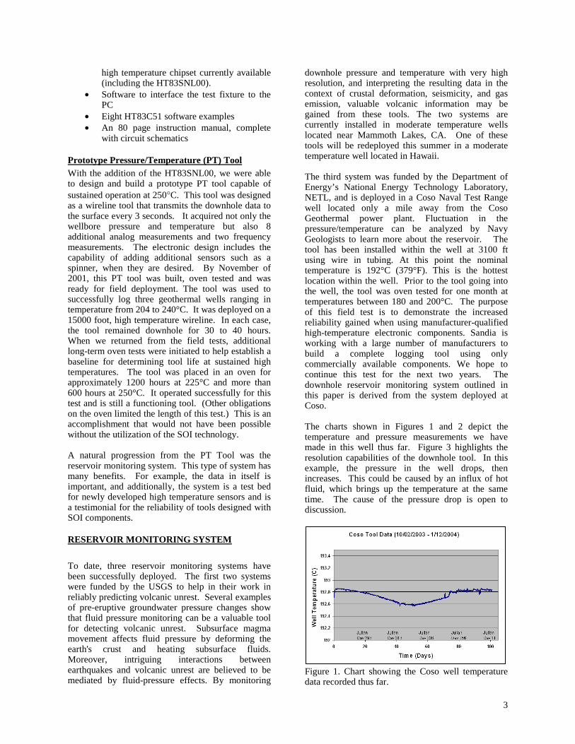
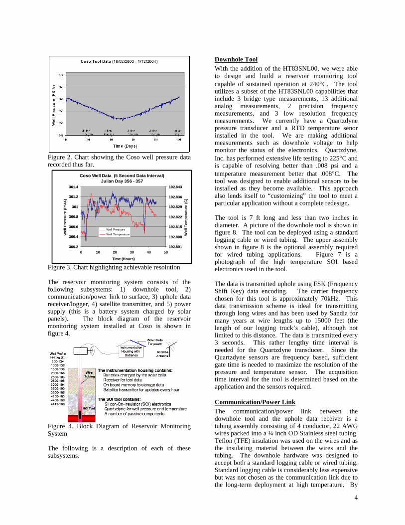
Figure 2. Chart showing the Coso well pressure data recorded thus far. Figure 3. Chart highlighting achievable resolution The reservoir monitoring system consists of the following subsystems: 1) downhole tool, 2) communication/power link to surface, 3) uphole data receiver/logger, 4) satellite transmitter, and 5) power supply (this is a battery system charged by solar panels). The block diagram of the reservoir monitoring system installed at Coso is shown in figure 4.
Figure 4. Block Diagram of Reservoir Monitoring System The following is a description of each of these subsystems.
Downhole Tool With the addition of the HT83SNL00, we were able to design and build a reservoir monitoring tool capable of sustained operation at 240°C. The tool utilizes a subset of the HT83SNL00 capabilities that include 3 bridge type measurements, 13 additional analog measurements, 2 precision frequency measurements, and 3 low resolution frequency measurements. We currently have a Quartzdyne pressure transducer and a RTD temperature senor installed in the tool. We are making additional measurements such as downhole voltage to help monitor the status of the electronics. Quartzdyne, Inc. has performed extensive life testing to 225°C and is capable of resolving better than .008 psi and a temperature measurement better that .008°C. The tool was designed to enable additional sensors to be installed as they become available. This approach also lends itself to “customizing” the tool to meet a particular application without a complete redesign. The tool is 7 ft long and less than two inches in diameter. A picture of the downhole tool is shown in figure 8. The tool can be deployed using a standard logging cable or wired tubing. The upper assembly shown in figure 8 is the optional assembly required for wired tubing applications. Figure 7 is a photograph of the high temperature SOI based electronics used in the tool. The data is transmitted uphole using FSK (Frequency Shift Key) data encoding. The carrier frequency chosen for this tool is approximately 70kHz. This data transmission scheme is ideal for transmitting through long wires and has been used by Sandia for many years at wire lengths up to 15000 feet (the length of our logging truck’s cable), although not limited to this distance. The data is transmitted every 3 seconds. This rather lengthy time interval is needed for the Quartzdyne transducer. Since the Quartzdyne sensors are frequency based, sufficient gate time is needed to maximize the resolution of the pressure and temperature sensor. The acquisition time interval for the tool is determined based on the application and the sensors required.
Communication/Power Link The communication/power link between the downhole tool and the uphole data receiver is a tubing assembly consisting of 4 conductor, 22 AWG wires packed into a ¼ inch OD Stainless steel tubing. Teflon (TFE) insulation was used on the wires and as the insulating material between the wires and the tubing. The downhole hardware was designed to accept both a standard logging cable or wired tubing. Standard logging cable is considerably less expensive but was not chosen as the communication link due to the long-term deployment at high temperature. By
Coso Well Data (5 Second Data Interval)Julian Day 356 - 357
360.2
360.4
360.6
360.8
361
361.2
361.4
0 10 20 30 40 50
TIme (Hours)
Wel
l Pre
ssu
re (
PS
IA)
192.801
192.808
192.815
192.822
192.829
192.836
192.843W
ell T
emp
erat
ure
(C
)
Well Pressure
Well Temperature
5
using stainless steel tubing, a metal-to-metal seal is utilized throughout the downhole hardware package. While standard high temperature logging cable is rated for operation at temperatures up to 300°C, it has been our experience that relying on elastomer seals for long-term deployment can lead to seal integrity problems. This eventually leads to cablehead issues that require the downhole tool to be removed from the well and serviced.
Uphole Data Receiver/Logger The uphole electronics consists of two elements. The first element is the uphole data receiver. It decodes the downhole data from the FSK encoded data scheme used to transmit the data uphole into a digital format compatible with the data logger. In this case, the data is decoded into a RS232 data format, which is compatible with most commercially available data loggers. The second element is the uphole data logger, which reads both the data from the downhole tool and any surface measurements that are required. The data logger chosen for this application is the Campbell Scientific Model CR10X. The data logger performs the following functions: 1) stores the downhole data to memory every 5 seconds, 2) makes additional surface data measurements, and 3) formats the data that will be transmitted via satellite for pseudo real-time display of the data. The additional surface data includes the downhole tool current, downhole tool supply voltage, wellbore pressure measured at the surface, solar-charged battery status, and surface temperature. All of this data helps to diagnose the condition of the downhole monitoring system remotely. Of these additional measurements, the downhole tool current is the measurement that helps the most in determining the “health” of the downhole system. For example, if there is suddenly a large increase in current, a catastrophic failure is identified. In the past, these failures have been related to shorting capacitors or electrical feedthrough problems at the cablehead. We have tried to eliminate these two failure mechanisms by 1) using 200V, 200C capacitors for 5 - 10 volt circuits and 2) replacing the standard logging cable with a wired tubing solution designed with metal seals. A sudden reduction in current is normally the result of a failed connection, which usually causes the loss of data or a reduction in the tool’s functionality. It is worth noting that a slight increasing drift in supply current is the normal result of IC degradation. The downhole reservoir monitoring tool has a 20,000 logic gate HT83SNL00 chip, an 8 bit microprocessor, 32,000 bytes of RAM and a host of analog circuits. When any transistor degrades, the level of leakage current normally goes up. However, the circuits may continue to run for a long time without noticeable loss of data or function. Thus, current will be our best detection method for tracking IC degradation.
Satellite Transmitter The satellite transmitter enables a means for the data from the Downhole Monitoring System to be viewed remotely anywhere in the world. The satellite utilized for this system is one of NOAA’s (National Oceanic and Atmospheric Administration) satellites namely the GOES (Geostationary Operational Environmental Satellite) satellite. Examples of the users of this satellite include the National Weather Service, Department of Defense, global research projects, Air and Ground Traffic Control, ship navigation, agriculture, and space services. Sandia’s Geothermal department is now a contributor to this system by providing pseudo real-time data of a Geothermal well and making this data available to anyone with WWW access. As stated earlier, the data in itself is important and additionally this system is a test bed for newly developed high temperature sensors, creating a testimonial for the reliability of tools designed with SOI components. The satellite transmitter chosen for this project is the Campbell Scientific Model HDR GOES.
Power Supply The power supply for the reservoir monitoring system consists of a solar array, control electronics, and batteries. The entire uphole assembly that includes the data receiver/logger, transmitter, and the power supply are contained on a small trailer that can be deployed in very remote locations.
In figure 5, the well is located in the middle of the photo. On top of the well is a 15 foot blue lubricator and a sheave wheel. The solar panel trailer can be seen to the left of the well. The trailer provides power downhole and houses the satellite transmitter. The satellite transmitter antenna can be seen on the left end of the trailer.
Figure 5. A photo of the uphole reservoir monitoring system.
6
LESSONS LEARNED
As with fielding any new tools, issues came up that required attention. These issues are highlighted below.
Fabrication issues Fabrication issues requiring research include potting compounds, printed circuit (PC) board materials, solders and fluxes. Sandia is aware of these issues and is presently researching other methods of lead attachments including improved solder and fluxes. Currently available high temperature solder is difficult to use, resulting in less than ideal electrical properties. This shortcoming is recognized by the industry and advances in this area will increase the reliability of high temperature tools. Sandia is planning on evaluating newly available potting compounds and alternative board materials that will sustain operation at 300°C within the next year. The PC board material currently utilized is polyimide. This material is suitable for operating temperatures up to 250°C (with limited life). An alternative board material capable of operating at 300°C is needed to overcome the polyimide temperature limitations while enabling us to fully utilize the many SOI components that will operate up to 300°C.
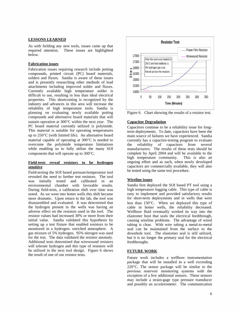
Field-tests reveal resistors to be hydrogen sensitive Field-testing the SOI based pressure/temperature tool revealed the need to further test resistors. The tool was initially tested and calibrated in an environmental chamber with favorable results. During field-tests, a calibration shift over time was noted. As we went into hotter wells this shift became more dramatic. Upon return to the lab, the tool was disassembled and evaluated. It was determined that the hydrogen present in the wells was having an adverse effect on the resistors used in the tool. The resistor values had increased 30% or more from their initial value. Sandia validated this hypothesis by setting up a test fixture that enabled resistors to be monitored in a hydrogen- enriched atmosphere. A gas mixture of 5% hydrogen, 95% nitrogen was used for the test. The data validated the resistor anomaly. Additional tests determined that wirewound resistors will tolerate hydrogen and this type of resistors will be utilized in the next tool design. Figure 6 shows the result of one of our resistor tests.
Figure 6. Chart showing the results of a resistor test.
Capacitor Degradation Capacitors continue to be a reliability issue for long-term deployments. To date, capacitors have been the main source of failures we have experienced. Sandia currently has a capacitor-testing program to evaluate the reliability of capacitors from several manufacturers. The results of these tests should be complete by April 2004 and will be available to the high temperature community. This is also an ongoing effort and as such, when newly developed capacitors are commercially available, they will also be tested using the same test procedure.
Wireline issues Sandia first deployed the SOI based PT tool using a high temperature logging cable. This type of cable is easy to implement and provided satisfactory results for short-term deployments and in wells that were less than 150°C. When we deployed this type of cable in hotter wells, the reliability decreased. Wellbore fluid eventually worked its way into the elastomer boot that seals the electrical feedthrough, causing wireline problems. The advantage of wired tubing is clear. With wire tubing a metal-to-metal seal can be maintained from the surface to the downhole tool. The elastomer seal is still utilized, but it is no longer the primary seal for the electrical feedthroughs.
FUTURE WORK
Future work includes a wellbore instrumentation package that will be installed in a well exceeding 220°C. The sensor package will be similar to the previous reservoir monitoring systems with the exception of a few additional sensors. These sensors may include a strain-gage type pressure transducer and possibly an accelerometer. The communication
Resistor Test
14800
15300
15800
16300
16800
17300
17800
0 50 100 150 200 250 300 350
Time (Minutes)
Oh
ms
Power Film Resistor
Wirewound ResistorAfter the oven w as heated to 250 C and had stablized, a 5% hydrogen gas w as f low ed across the resistors.
7
/power link will be wired tubing with high temperature fiber optic cable within the same tube. This enhancement will enable us to test not only HT components for long term, but also fiber and the associated surface measurement systems. Future plans also include a MWD tool that will be deployed while rotary drilling and a new 225°C Diagnostics-while-Drilling (DWD) tool, which will greatly increase the driller's understanding of what is happening downhole in real time. All of these tools will be based on the HT chipset that is commercially available. Sandia will be helping industry with the design and implementation of high temperature Dewarless tools. Several Geothermal companies have requested our learning kit and are presently working on tool designs based on the HT chipset. New SOI components will become available in the future to further enhance the performance of high temperature tools. This is made possible through the JIP (Joint Industry Partnership) program, which is lead by Honeywell. The program’s funding is shared between DOE, NETL and industry to support deep (>20,000 ft) natural gas production within the US.
CONCLUSIONS
The time is right to exploit the use of high temperature electronics based on SOI technology. With the addition of the HT83SNL00 device, the high temperature industry now has enough components to design and implement Dewarless tools. Sandia has achieved a barefoot logging tool that others have dreamed of for the past 20 years. A natural progression from the PT Tool was the reservoir monitoring system. The benefit from this type of system is threefold. The data in itself is important and additionally, the system is a test bed for newly developed high temperature sensors and is a testimonial for the reliability of tools designed with SOI components.
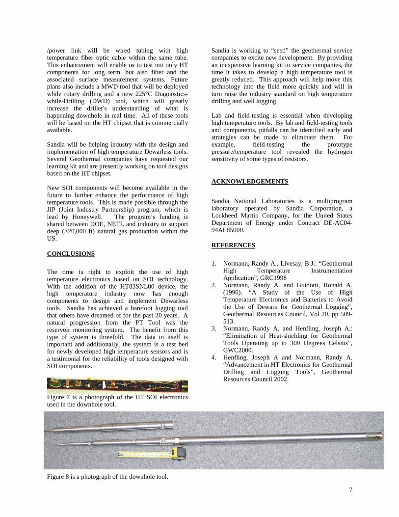
Figure 7 is a photograph of the HT SOI electronics used in the downhole tool. Figure 8 is a photograph of the downhole tool.
Sandia is working to “seed” the geothermal service companies to excite new development. By providing an inexpensive learning kit to service companies, the time it takes to develop a high temperature tool is greatly reduced. This approach will help move this technology into the field more quickly and will in turn raise the industry standard on high temperature drilling and well logging. Lab and field-testing is essential when developing high temperature tools. By lab and field-testing tools and components, pitfalls can be identified early and strategies can be made to eliminate them. For example, field-testing the prototype pressure/temperature tool revealed the hydrogen sensitivity of some types of resistors.
ACKNOWLEDGEMENTS
Sandia National Laboratories is a multiprogram laboratory operated by Sandia Corporation, a Lockheed Martin Company, for the United States Department of Energy under Contract DE-AC04-94AL85000.
REFERENCES
1. Normann, Randy A., Livesay, B.J.: “Geothermal
High Temperature Instrumentation Application”, GRC1998
2. Normann, Randy A. and Guidotti, Ronald A. (1996). “A Study of the Use of High Temperature Electronics and Batteries to Avoid the Use of Dewars for Geothermal Logging”, Geothermal Resources Council, Vol 20, pp 509-513.
3. Normann, Randy A. and Henfling, Joseph A.: “Elimination of Heat-shielding for Geothermal Tools Operating up to 300 Degrees Celsius”, GWC2000.
4. Henfling, Joseph A and Normann, Randy A. “Advancement in HT Electronics for Geothermal Drilling and Logging Tools”, Geothermal Resources Council 2002.