US Army Corps of Engineers Engineer Research and Development Center High Temperature Hot Water Generator Safety Valve Research at Wright-Patterson AFB, OH Investigation of Chronic Safety Valve Leaks Michael K. Brewer, Charles M. Schmidt, and John Tanner Wright-Patterson AFB (WPAFB) tasked the U.S. Army Construction Engineering Research Laboratory (CERL) to investigate the best way to resolve the problem of incorrect safety valves installed on fired pressure vessels in high temperature hot water (HTHW) generators. Additionally, WPAFB requested help in controlling system pressure in the HTHW system during large load swings, and guidance on how to pipe expansion tank discharge to a blowoff tank. CERL researchers visited the site, inspected the system, researched relevant specifications, and recommended that: (1) the screen interface for the computerized plant data recording system at Plant 1240 be modified to trend plant pressure and N 2 expansion tank level to help troubleshoot pressure control problems, (2) two “V” safety valves be installed on each HTHW unit, and (3) the blowoff valve, piping, and tank configuration be modified to eliminate water hammer. CERL Technical Report 99/91 November 1999 Approved for public release; distribution is unlimited. WWW.CECER.ARMY.MIL/TECHREPORTS
Transcript
US Army Corpsof EngineersEngineer Research andDevelopment Center
High Temperature Hot WaterGenerator Safety Valve Researchat Wright-Patterson AFB, OHInvestigation of Chronic Safety Valve Leaks
Michael K. Brewer, Charles M. Schmidt, and John Tanner
Wright-Patterson AFB (WPAFB) tasked the U.S.Army Construction Engineering ResearchLaboratory (CERL) to investigate the best wayto resolve the problem of incorrect safety valvesinstalled on fired pressure vessels in hightemperature hot water (HTHW) generators.Additionally, WPAFB requested help incontrolling system pressure in the HTHWsystem during large load swings, and guidanceon how to pipe expansion tank discharge to ablowoff tank.
CERL researchers visited the site, inspected thesystem, researched relevant specifications, andrecommended that: (1) the screen interface forthe computerized plant data recording system atPlant 1240 be modified to trend plant pressureand N2 expansion tank level to help troubleshootpressure control problems, (2) two “V” safetyvalves be installed on each HTHW unit, and (3)the blowoff valve, piping, and tank configurationbe modified to eliminate water hammer.
CERL Technical Report 99/91November 1999
Approved for public release; distribution is unlimited. WWW.CECER.ARMY.MIL/TECHREPORTS
2 CERL TR 99/91
Foreword
This study was conducted for Wright-Patterson Air Force Base (WPAFB) underMilitary Interdepartmental Purchase Request (MIPR) No. NCEGCE99710201,dated 16 December 1998. The technical monitor was Tony Day.
The work was performed by the Energy Branch (CF-E), of the Facilities Division(CF), U.S. Army Construction Engineering Research Laboratory (CERL). Char-les M. Schmidt is associated with Schmidt and Associates, Inc. The CERL prin-cipal investigator was Michael K. Brewer. Larry M. Windingland is Chief,CEERD-CF-E and Dr. L. Michael Golish is Chief, CEERD-CF. The CERL techni-cal editor was William J. Wolfe, Information Technology Laboratory.
The Director of CERL is Dr. Michael J. O’Connor.
DISCLAIMER
The contents of this report are not to be used for advertising, publication, or promotional purposes. Citation of trade namesdoes not constitute an official endorsement or approval of the use of such commercial products. All product names andtrademarks cited are the property of their respective owners.
The findings of this report are not to be construed as an official Department of the Army position unless so designated byother authorized documents.
DESTROY THIS REPORT WHEN IT IS NO LONGER NEEDED. DO NOT RETURN IT TO THE ORIGINATOR.
Corrosion from Leaking.....................................................................................................19
5 July 1999 Site Visit.......................................................................................................... ............ 20
Investigation and Observations.........................................................................................20
Data Analysis and Recommendations ..............................................................................20
6 Summary of Recommendations.............................................................................................. 28
Appendix A: Safety Valve Name Plate Data................................................................................ 29
Appendix B: Safety Valve Body Loading .................................................................................... 31
Distribution ................................................................................................................... ...................... 33
Plant staff at Building 1240, Wright-Patterson Air Force Base (WPAFB), ob-served that the high temperature hot water (HTHW) generators did not have thecorrect safety valves installed for fired pressure vessels. Based on the U.S. ArmyConstruction Engineering Research Laboratory’s (CERL’s) research experiencewith central heating plants (CHPs) and, in particular, coal-fired plants, WPAFBcontacted CERL for information on safety valve requirements and to discuss thebest way to resolve the problem. Specifically, plant staff requested support ininvestigating the correct type and size valve needed, and also in controlling sys-tem pressure in the HTHW system in Plant 1240 during large load swings.These swings cause over-pressure conditions and subsequent opening of the gen-erator relief valves. Once the HTHW safety valves become unseated, they aremore susceptible to leaking and discharging at pressures below their originalsetpoint.
After CERL researchers made their initial site visit, WPAFB staff also requestedadditional guidance on how to pipe the expansion tank discharge to the blowofftank, including information on the sizing and location of the blowoff line pipingto eliminate large vibrations in the piping when discharging HTHW to the blow-off tank.
Objectives
The objectives of this study were to: (1) provide base engineering staff withneeded research and assistance to determine the correct safety valve combina-tion at the HTHW plant at WPAFB, and (2) develop a long-term solution to thepressure control problems at the plant.
8 CERL TR 99/91
Approach
The research and assistance encompassed the following tasks:
1. Analyze Current System. CERL researchers and a CERL contractor, Schmidtand Associates, Inc. (SAI), inspected the current pressure relief system at Plant1240.
2. Specify Correct System at Plant 1240. The team specified the correct size andtype of valves and piping to meet the current boiler and pressure vessel code.
3. Investigate Pressure Control System (specified as an optional task, to be done iffunds were available). The team inspected the pressure relief system at Plant770 or other plant at WPAFB, investigated the cause of excessive pressure tran-sients at Plant 1240, and recommended system modifications.
4. Document Technical Support Findings. Based on the information gathered andanalyzed, a letter report was delivered to the sponsor describing the results ofTasks 1-3, which included recommendations and addressed any sponsor com-ments.
5. Specify Correct Expansion Tank to Blowoff Tank Piping (added June 1999). Theteam specified the correct size and type of valves and piping to meet the currentboiler and pressure vessel code and enable plant operators to control systempressure more effectively.
6. Document Results (added June 1999). The letter report described in Task 4 wasamended to include the results of Task 5.
Mode of Technology Transfer
It is anticipated that lessons learned from this project will also be transmitted toHeadquarters, Air Force Civil Engineering Support Agency (HQAFCESA) andthe U.S. Army Corps of Engineers Directorate of Military Programs (CEMP-ET)for inclusion in guide specifications and technical notes.
CERL TR 99/91 9
Units of Weight and Measure
U.S. standard units of measure are used throughout this report. A table of con-version factors for Standard International (SI) units is provided below.
SI conversion factors
1 in. = 2.54 cm 1 gal = 3.78 L
1 ft = 0.305 m 1 lb = 0.453 kg
1 sq in. = 6.452 cm2 1 psi = 6.89 kPa
1 sq ft = 0.093 m2 °F = (°C x 1.8) + 32
1 cu ft = 0.028 m3
10 CERL TR 99/91
2 December 1998 Site Visit
Investigation and Observations
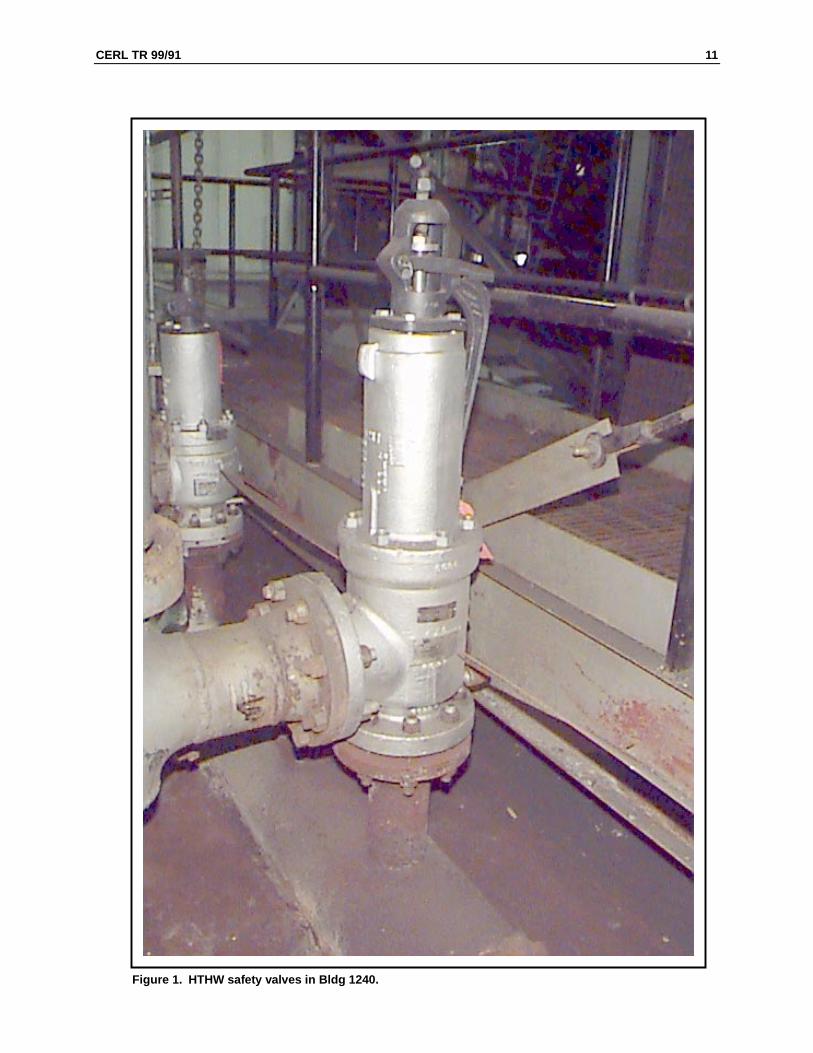
CERL and SAI conducted a site visit to WPAFB Plant 1240 on 22 December1998. During the site visit, the investigation team examined the installed safetyvalves (Figure 1), reviewed plant drawings, recorded plant conditions, and inter-viewed plant staff. The team observed that the installed safety valves were notmarked as the type required by the American Society of Mechanical Engineers(ASME) Boiler and Pressure Vessel Code (ASME BPVC) Section I Part PG-110.ASME BPVC requires fired pressure vessels to be protected with “V” stampedsafety valves. Additionally, the legibility of the valve data was poor. Table 1 liststhe seven items required to appear on the name plate or etched on the valvebody.
Two valves are required on each of the four HTHW units, for a total of eightsafety valves. Only two of the installed valves had “V” stamps. One additionalvalve may have had a “V” stamp, but it was hidden from view by the HTHWgenerator piping. Three valves had “UV” stamps. “UV” valves are not permittedon fired pressure vessels built and operated as ASME BPVC Section I systems.Two valves had neither “V” nor “UV” stamps. Appendix A to this report tabu-lates the legible data collected as part of this inspection.
The team was concerned that the boiler inspectors did not note any of these dis-crepancies in Section V (Inspection of Safety Devices) of the most recent inspec-tion reports.
Data Analysis and Recommendations
The team reviewed the data and the ASME BPVC. The team observed theplant’s margin for operation would not accommodate large swings in pressure.Interviews with the operators revealed that the mix of two- and three-way con-trol valves on the HTHW system, when coupled with the event of rapidly shut-ting down on a HTHW/steam converter, causes the return temperature to rapidlyincrease 15 to 20 °F.
CERL TR 99/91 11
Figure 1. HTHW safety valves in Bldg 1240.
12 CERL TR 99/91
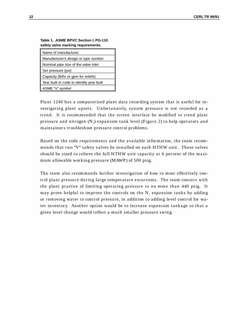
Table 1. ASME BPVC Section I, PG-110safety valve marking requirements.
Name of manufacturer
Manufacturer’s design or type number
Nominal pipe size of the valve inlet
Set pressure (psi)
Capacity (lb/hr or gpm for reliefs)
Year built or code to identify year built
ASME “V” symbol
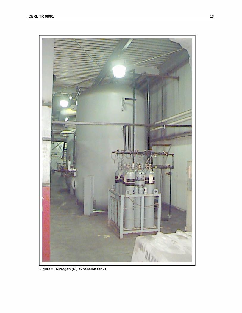
Plant 1240 has a computerized plant data recording system that is useful for in-vestigating plant upsets. Unfortunately, system pressure is not recorded as atrend. It is recommended that the screen interface be modified to trend plantpressure and nitrogen (N2) expansion tank level (Figure 2) to help operators andmaintainers troubleshoot pressure control problems.
Based on the code requirements and the available information, the team recom-mends that two “V” safety valves be installed on each HTHW unit. These valvesshould be sized to relieve the full HTHW unit capacity at 6 percent of the maxi-mum allowable working pressure (MAWP) of 500 psig.
The team also recommends further investigation of how to most effectively con-trol plant pressure during large temperature excursions. The team concurs withthe plant practice of limiting operating pressure to no more than 440 psig. Itmay prove helpful to improve the controls on the N2 expansion tanks by addingor removing water to control pressure, in addition to adding level control for wa-ter inventory. Another option would be to increase expansion tankage so that agiven level change would reflect a much smaller pressure swing.
CERL TR 99/91 13
Figure 2. Nitrogen (N 2) expansion tanks.
14 CERL TR 99/91
3 Safety Valve Specification
The team recommends that two “V” stamped valves be installed on each of thefour HTHW generators. The valves must meet the following requirements.
Number of Valves
ASME BPVC Section I, PG 67.1 requires that 2 “V” stamp valves be installedwhere the bare tube water heating surface of the HTHW units is greater than500 sq ft.
Capacity
ASME BPVC Section I, PG 67.2.4 requires that the relieving capacity of thevalve system for HTHW units be the maximum output at the nozzle in Btu/hrdivided by 1000. For the coal-fired units, the capacity of the pair of valves mustbe equal to or greater than 143,000 lb/hr (110 percent of full load, 2-hour peakload). For the gas-fired unit, the capacity of the pair of valves must be equal toor greater than 88,000 lb/hr (110 percent of full load, 2-hour peak load). ASMESection I, PG 71.1 requires that, when two safety valves are mounted, thesmaller capacity valve shall not have a capacity of less that 50 percent of thelarger capacity valve.
Setpoint
ASME BPVC Section I, PG-67.3 requires that the setpoint of one or more of thevalves be at or below the MAWP of the pressure vessel. The highest setting ofany of the valves in a pressure relief system shall not exceed the MAWP by morethan 3 percent. The units at Plant 1240 have a MAWP of 500 psig. One of the“V” valves will need to be set at or below 500 psig. The second valve will need tobe set at or below 515 psig. Footnote 18 to ASME BPVC Section I, PG-67.3 rec-ommends that HTHW safety valves be set as high as possible above the operat-ing pressure as they are much more susceptible to damage and leakage than thesteam safety valve. Also relieving flashing hot water from the safety valves ismore damaging to the valve than relieving steam. However, the valves at Plant
CERL TR 99/91 15
1240 still cannot be set above 500 psig and 515 psig due to the MAWP limit.ASME BPVC Section I, PG-72.2 allows a popping tolerance of 10 psi for pres-sures between 300 and 1000 psi. Therefore, the 500 psig valve may actuallyopen between 490 psig and 510 psig. ASME BPVC Section I, PG-72.3 prohibitsadjusting the set pressure more than 5 percent above or below the pressuremarked by the manufacturer without a determination by the manufacturer thatthe new setting is within the spring design range.
Water Temperature Limits
ASME BPVC Section I, PG-67.5 requires that HTHW safety valves be con-structed and set to relieve water at the saturation temperature of the valve set-point. For Plant 1240, the valve set at 500 psig must be able to operate with wa-ter at 464 °F, and the valve set at 515 psig must be able to operate with water at467 °F.
Materials
ASME BPVC Section I, PG-67.5 requires that HTHW safety valves be con-structed with a closed bonnet. ASME BPVC Section I, PG-67.7 prohibits the useof bronze parts in HTHW safety valves. ASME BPVC Section I, PG-71.37 pro-hibits the use of cast iron bodies in HTHW safety valves.
Blowdown Limit
ASME BPVC Section I, PG-69.1.4 and PG 72.1 require that HTHW safety valvesnot blow down to a pressure less than 10 percent of the set pressure. For plant1240, the 500 psig relief must reseat before the pressure drops to 450 psig. The515 psig safety must reseat before reaching 463.5 psig.
Safety Valve Connection to the Unit
ASME BPVC Section I, PG-71.2 requires that HTHW safety valve be attached asclosely as possible to the HTHW unit. The connecting piping shall not be longerthan the face-to-face dimension of the corresponding “T” fitting of the same pipeand pressure specification for the unit. ASME BPVC Section I, PG-71.3 requiresthat piping between the HTHW unit and safety valve have a cross-sectional areaequal to or greater than the safety valve inlet.
16 CERL TR 99/91
Safety Valve Discharge and Drains
ASME BPVC Section I, PG-71.3 requires that HTHW safety valves dischargeinto a section of pipe that is as short and straight as possible. ASME BPVC Sec-tion VII, C4.130 recommends that the manufacturer be consulted if anythingmore than a short elbow and drip pan is attached to a safety valve. ASME BPVCSection I, PG-71.3 requires that HTHW safety valves greater than nominal pipesize (NPS) 2½ have an open gravity drain on the body below the valve seat witha hole not less that NPS 3/8 (0.675 in.). Ample drains for steam and condensa-tion shall be provided. Cast iron body safety relief valves are prohibited onHTHW units. The discharging pipe on HTHW safety valves shall also have pro-vision for discharge of water as well as steam. All the safety valves at Plant1240 are greater than NPS 2½ (3x4 and 4x6). ASME BPVC Section VII, C2.310recommends that the discharge piping and drain be open to the atmosphere andfree to expand without imposing loads on the safety valve. To minimize thechance of roof damage, a safety relief valve separator should be installed to allowthe water to drain separately to the plant drains instead of going to the roof withthe steam. It is vitally important that the piping and the separator not impose aload on the safety valve. The valve will not open at the set pressure if any exter-nal load is imposed. Appendix B cites an incident where an externally loadedsafety valve would not open until the set pressure was exceeded by 100 percent.
Markings
ASME BPVC Section I, PG-110 requires that HTHW safety valves be markedwith a “V” stamp and with the data mentioned in Table 1 of this report. Thestamp shall be plainly marked in a durable fashion. ASME BPVC Section VII,C4.120 strongly recommends that, if a valve’s setting is changed from the manu-facturer’s setting, the old setting must be marked out, but left legible. The newsetting should be reviewed with the valve manufacturer to ensure valve compli-ance. ASME BPVC Section VII, C4.230 strongly recommends that the repairingactivity attach a nameplate identifying the repairer and the date of repair.BPVC Section VII, C4.230 also strongly recommends that the original valvenameplate never be removed from the valve. To remove doubt as to the meaningand intent of the marking requirement in ASME BPVC Section I, PG-110, thecommittee issued interpretation I-92-38 Section I, PG-110 on 14 October 1992:
Question: Must the safety valves required for it (sic) Section I boiler be
“V” stamped?
Answer: Yes.
CERL TR 99/91 17
UV Valves Prohibited
ASME BPVC Section VII, C4.220, in its discussion of safety relief valves and re-lief valves for liquid, specifically states the HTHW safety relief valves must meetSection I (“V” valve) requirements. To address the issue that UV valves are notpermissible on non-steam Section I vessels, the committee issued interpretationI-92-42 Section I, PVG-12.5 on 14 October 1992:
Question: May a Section VIII “UV” stamped safety valve be used on a
Section I organic fluid vaporizer?
Answer: No, the overpressure used to determine relieving capacity and
the blowdown requirements used for “UV” valves differ from those Sec-
tion I “V” stamped safety valves.
18 CERL TR 99/91
4 Other Safety Valve Requirements
Due to the susceptibility of HTHW safety valves to damage and leakage, theplant will need to observe extra precautions operating and maintaining valves.
Lift Tests
ASME BPVC Section I, PG-73.1.3 prohibits manually lifting a HTHW safety re-lief valve when the water temperature exceeds 200 °F. However, if a lift check isdone to verify that the mechanism is free, the valve shall be subject to at least 75percent of set pressure during the test (ASME BPVC Section VII, C2.330).
Accumulation Tests
Although steam safety valve capacity can be determined with an accumulationtest, ASME BPVC Section I, NMA A-46.1 strongly discourages doing (i.e., opera-tive wording is “should not” do) accumulation tests on an HTHW safety valve.An accumulation test is firing the boiler at maximum capacity and shutting allother steam discharge outlets. ASME BPVC Section I, NMA A-46.3 prohibitsverifying safety valve capacity by measuring feedwater in an accumulation test.
Gagging of Safety Valves
ASME BPVC Section VII, C2.430 prohibits the gagging of safety valves on oper-ating units unless the capacity of the remaining valves equals or exceeds the re-quirements for the HTHW unit.
ASME BPVC Section VII, C4.120 strongly recommends that safety valves not bestored or transported on their sides. Care should be taken to maintain verticalalignment of the valve when installing or transporting.
Valve Records
ASME BPVC Section VII, C4.120 and C4.230 strongly recommend that detailedinspection, operation, testing, pressure setting, and valve repair records bemaintained.
Valve Testing
ASME BPVC Section VII, C4.130 strongly recommends that safety valves bethermally stable before any testing. Additionally, a safety valve gag should notbe applied until the valve has been at approximately 80 percent of operatingpressure for 2 hours to avoid spindle damage from thermal expansion.
Plant Operating Pressure
ASME BPVC Section VII, C4.130 strongly recommends that the system operat-ing pressure be at least 7 percent below the safety valve setpoint and not lessthat 30 psi below the safety valve setpoint. For the HTHW units at Plant 1240,the maximum recommended operation pressure should not exceed 465 psig.ASME BPVC Section VII, C4.222 strongly recommends the system operatingpressure be below the closing pressure of a safety relief valve (blowdown). AtPlant 1240, the 500 psig safety valve can blowdown 10 percent of 500 psig to 450psig. If the 10 psig tolerance is considered, the valve can blowdown as low as441.5 psig.
Corrosion from Leaking
ASME BPVC Section VII, C9.350 strongly cautions operators to guard againstleaking safety valves and connections that may drip condensate on pressure ves-sel parts. The water and condensate may run under casing and insulation andrapidly corrode the pressure vessel part.
20 CERL TR 99/91
5 July 1999 Site Visit
Investigation and Observations
On 1 July 1999, CERL and SAI visited WPAFB to collect data and assess theproblems reported with the blowoff valve and blowoff piping. The assessmentteam collected data from the logs, inspected the systems, and interviewed plantstaff to determine the cause of the problem. The team observed that the rootcause of the problems with blowoff piping vibrations is that the operators have todischarge HTHW frequently to maintain the N2 tank level.
The team concluded that the N2 system is undersized for the volume changetransients now experienced by the plant. The most complete solution would beto greatly increase the N2 tankage. To handle the reported plant water volumeincrease of almost 200 cu ft (ranges calculated of 108 to 189 cu ft), the N2 tank-age would need to be increased almost 13 times to avoid letting the water level inthe N2 tanks increase more than 2 in. The team also examined other less costlyoptions to reduce stress on the piping from discharging HTHW to the blowofftank.
Data Analysis and Recommendations
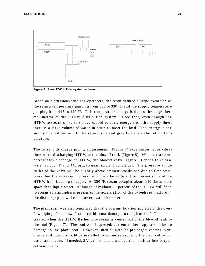
The total volume HTHW distribution for Plant 1240 is 216,000 gal. There arefive HTHW generators, three coal-fired units, and two gas/oil-fired units, as de-scribed in the December 1998 site visit. (Figure 3 shows a system schematic forPlant 1240.) The return temperature is typically about 350 °F at 425 psig.HTHW units are brought on line to best match the system load with the fewestnumber of units operating at maximum capacity. Additionally, before starting anon-coming HTHW unit, HTHW is circulated in the cold unit to heat the furnacesurfaces. This reduces thermal stress and corrosion in the on-coming units.During such transitions (bringing units on- or offline), the distribution bulk tem-perature can vary causing the water volume to shrink or swell. Another type ofevent is the rapid loss of load due to a HTHW-to-steam converter being rapidlyshutdown. This causes the bulk water temperature of the return and supplylines to increase, and causes the system volume to increase (i.e., to swell into theN2 tank).
CERL TR 99/91 21
Figure 3. Plant 1240 HTHW system schematic.
Based on discussions with the operators, the team defined a large excursion asthe return temperature jumping from 300 to 330 °F and the supply temperaturejumping from 415 to 420 °F. This temperature change is due to the large ther-mal inertia of the HTHW distribution system. Note that, even though theHTHW-to-steam converters have ceased to draw energy from the supply lines,there is a large volume of water in route to meet the load. The energy in thesupply line will move into the return side and greatly elevate the return tem-perature.
The current discharge piping arrangement (Figure 4) experiences large vibra-tions when discharging HTHW to the blowoff tank (Figure 5). When a transientnecessitates discharge of HTHW, the blowoff valve (Figure 6) opens to releasewater at 350 °F and 440 psig to near ambient conditions. The pressure at theoutlet of the valve will be slightly above ambient conditions due to flow resis-tance, but the increase in pressure will not be sufficient to prevent some of theHTHW from flashing to vapor. At 350 °F, steam occupies about 180 times morespace than liquid water. Although only about 20 percent of the HTHW will flashto steam at atmospheric pressure, the acceleration of the two-phase mixture inthe discharge pipe will cause severe water hammer.
The plant staff was also concerned that the present location and size of the over-flow piping of the blowoff tank could cause damage to the plant roof. The steamcreated when the HTHW flashes into steam is vented out of the blowoff tank tothe roof (Figure 7). The roof was inspected; currently there appears to be nodamage to the plant roof. However, should there be prolonged venting, ventdrains and piping should be installed to minimize exposing the flat roof to hotwater and steam. If needed, SAI can provide drawings and specifications of typi-cal vent drains.
Blowoff Tanks
Boilers
Return
Supply
Nitrogen Tanks
Blowoff Valve
Safety Valve
Tank 1 Tank 2
22 CERL TR 99/91
Figure 4. HTHW blowoff piping.
Figure 5. HTHW blowoff tanks.
CERL TR 99/91 23
Figure 6. HTHW blowoff valve.
The team and plant staff concluded that the valve is not placed in the best posi-tion to minimize water hammer when discharging HTHW to the blowoff tanks.The team recommended that the blowoff valve would have the least water ham-mer when located to discharge into the top of the blowoff tank (Figure 8). Thiswould eliminate two-phase flow in the discharge line from the blowoff valve tothe blowoff tank.
With the large amount of discharge and makeup to control plant pressure, it iscritical to aggressively monitor and control the dissolved oxygen level in the sys-tem. Large amounts of dissolved oxygen in the water can cause pitting on theinsides of the piping, HTHW generators and blowoff tanks. The pitting will beworse in components where the HTHW temperature dramatically increases.
As mentioned above, the root cause of the pressure control and HTHW dischargewater hammer is an inadequate N2 tank surge volume. Since the N2 tank is un-dersized, the plant staff has to discharge and charge water to the system fre-quently. To eliminate or minimize water hammer, CERL and SAI recommendedseveral options for modifying the pipe leading to the blowoff tank. The mostcomplete solution would be to greatly increase the number of N2 tanks. However,that solution does not seem financially acceptable at this time.
24 CERL TR 99/91
Figure 7. Blowoff tank vent on the roof of Bldg 1240.
CERL TR 99/91 25
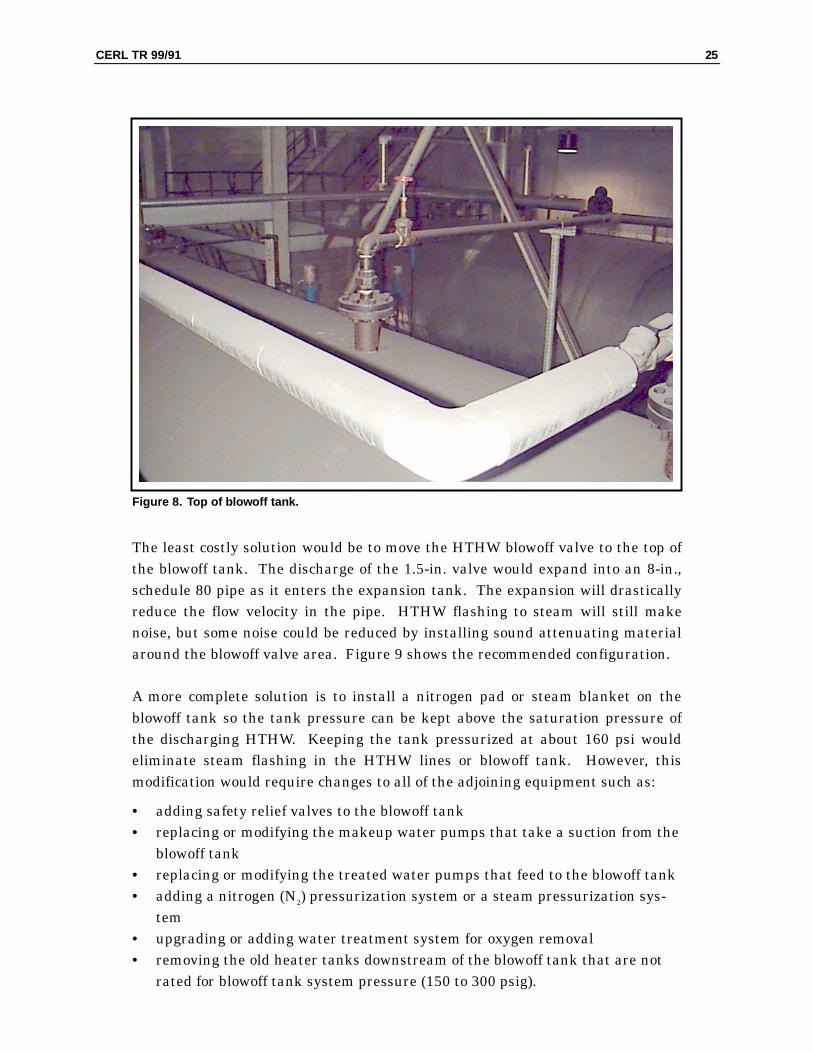
Figure 8. Top of blowoff tank.
The least costly solution would be to move the HTHW blowoff valve to the top ofthe blowoff tank. The discharge of the 1.5-in. valve would expand into an 8-in.,schedule 80 pipe as it enters the expansion tank. The expansion will drasticallyreduce the flow velocity in the pipe. HTHW flashing to steam will still makenoise, but some noise could be reduced by installing sound attenuating materialaround the blowoff valve area. Figure 9 shows the recommended configuration.
A more complete solution is to install a nitrogen pad or steam blanket on theblowoff tank so the tank pressure can be kept above the saturation pressure ofthe discharging HTHW. Keeping the tank pressurized at about 160 psi wouldeliminate steam flashing in the HTHW lines or blowoff tank. However, thismodification would require changes to all of the adjoining equipment such as:
• adding safety relief valves to the blowoff tank• replacing or modifying the makeup water pumps that take a suction from the
blowoff tank• replacing or modifying the treated water pumps that feed to the blowoff tank• adding a nitrogen (N2) pressurization system or a steam pressurization sys-
tem• upgrading or adding water treatment system for oxygen removal• removing the old heater tanks downstream of the blowoff tank that are not
rated for blowoff tank system pressure (150 to 300 psig).
26 CERL TR 99/91
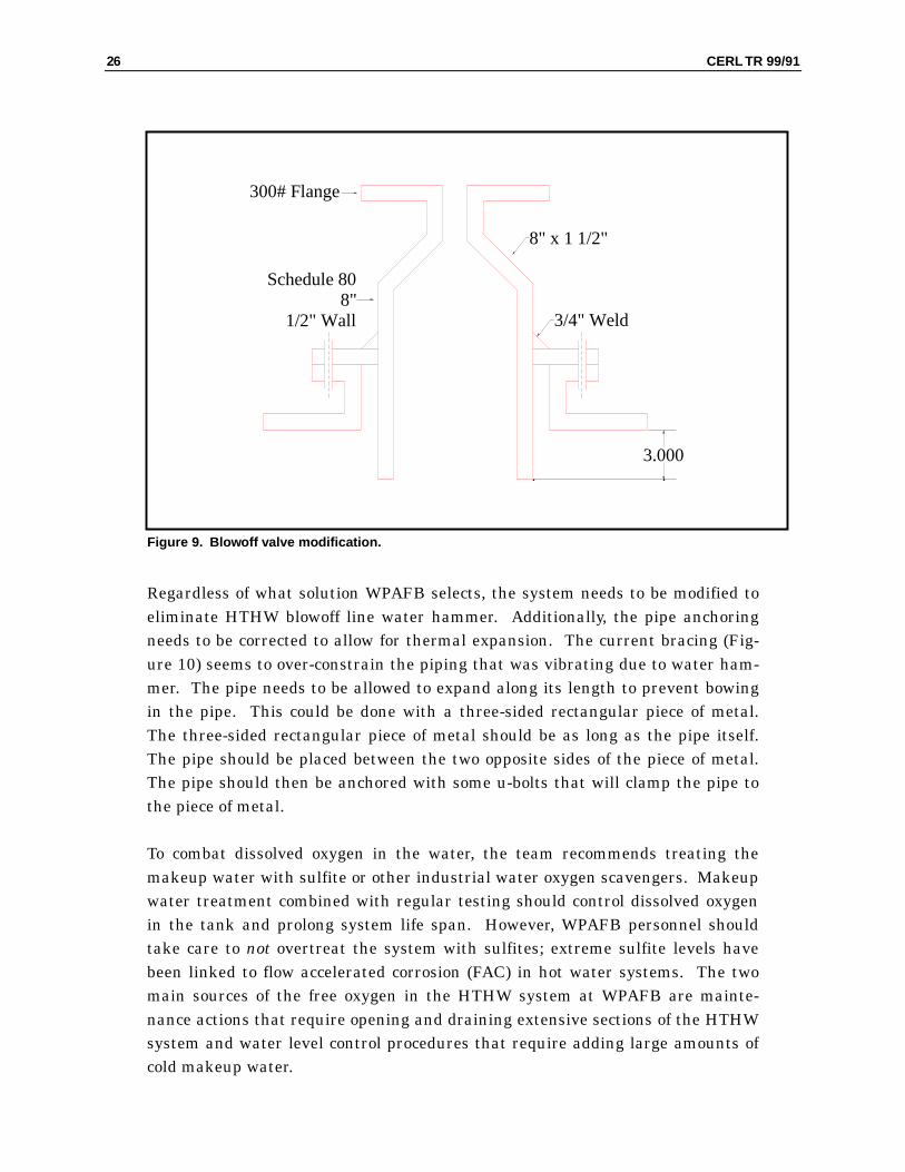
Figure 9. Blowoff valve modification.
Regardless of what solution WPAFB selects, the system needs to be modified toeliminate HTHW blowoff line water hammer. Additionally, the pipe anchoringneeds to be corrected to allow for thermal expansion. The current bracing (Fig-ure 10) seems to over-constrain the piping that was vibrating due to water ham-mer. The pipe needs to be allowed to expand along its length to prevent bowingin the pipe. This could be done with a three-sided rectangular piece of metal.The three-sided rectangular piece of metal should be as long as the pipe itself.The pipe should be placed between the two opposite sides of the piece of metal.The pipe should then be anchored with some u-bolts that will clamp the pipe tothe piece of metal.
To combat dissolved oxygen in the water, the team recommends treating themakeup water with sulfite or other industrial water oxygen scavengers. Makeupwater treatment combined with regular testing should control dissolved oxygenin the tank and prolong system life span. However, WPAFB personnel shouldtake care to not overtreat the system with sulfites; extreme sulfite levels havebeen linked to flow accelerated corrosion (FAC) in hot water systems. The twomain sources of the free oxygen in the HTHW system at WPAFB are mainte-nance actions that require opening and draining extensive sections of the HTHWsystem and water level control procedures that require adding large amounts ofcold makeup water.
3/4" Weld
Schedule 808"
1/2" Wall
8" x 1 1/2"
300# Flange
3.000
CERL TR 99/91 27
Figure 10. Current blowoff tank bracing.
28 CERL TR 99/91
6 Summary of Recommendations
CERL and SAI recommend the following improvements to WPAFB Plant 1240pressure controls:
1. Plant 1240 has a computerized plant data recording system that is useful for in-vestigating plant upsets. Unfortunately, system pressure is not recorded as atrend. It is recommended that the screen interface be modified to trend plantpressure and N2 expansion tank level to help operators and maintainers trouble-shoot pressure control problems.
2. Based on code requirements and available information, the team recommendsthat WPAFB install two “V” safety valves on each HTHW unit. These valvesshould be sized to relieve the full HTHW unit capacity at 6 percent of the MAWPof 500 psig.
3. To eliminate the HTHW blowoff line water hammer, WPAFB should modify theblowoff valve, piping, and tank configuration. The N2 tank surge volume is cur-rently undersized. Because of this lack of capacity, operators must discharge wa-ter and add makeup water excessively. The least disruptive system modificationto alleviate this problem would be to move the blowoff valve to the top of theblowoff tank.
CERL TR 99/91 29
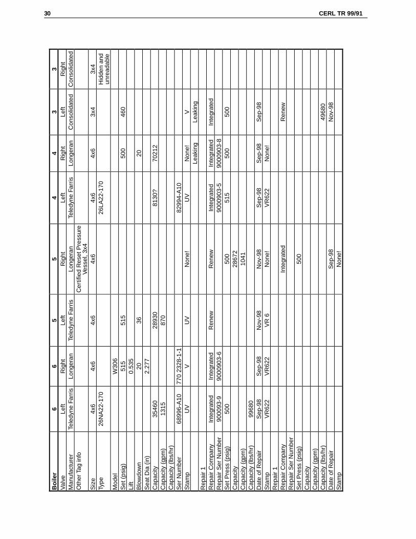
Appendix A: Safety Valve Name PlateData
30 CERL TR 99/91
Boi
ler
66
55
44
33
Val
veLe
ftR
ight
Left
Rig
htLe
ftR
ight
Left
Rig
htM
anuf
actu
rer
Tele
dyne
Far
risLo
nger
anTe
ledy
ne F
arris
Long
eran
Tele
dyne
Far
risLo
nger
anC
onso
lidat
edC
onso
lidat
edO
ther
Tag
info
Cer
tifie
d R
eset
Pre
ssur
eVe
ssel
, 3x4
Siz
e4x
64x
64x
64x
64x
64x
63x
43x
4Ty
pe26
NA
22-1
7026
LA22
-170
Hid
den
and
unre
adab
leM
odel
W30
6S
et (
psig
)51
551
550
046
0Li
ft0.
535
Blo
wdo
wn
2036
20S
eat D
ia (
in)
2.27
7C
apac
ity35
460
2893
081
30?
7021
2C
apac
ity (
gpm
)13
1587
0C
apac
ity (
lbs/
hr)
Ser
Num
ber
6899
6-A
1077
0 23
28-1
-182
994-
A10
Sta
mp
UV
VU
VN
one!
UV
Non
e!V
Leak
ing
Leak
ing
Rep
air
1R
epai
r C
ompa
nyIn
tegr
ated
Inte
grat
edR
enew
Ren
ewIn
tegr
ated
Inte
grat
edIn
tegr
ated
Rep
air
Ser
Num
ber
9000
93-9
9000
903-
690
0090
3-5
9000
903-
8S
et P
ress
(ps
ig)
500
500
515
500
500
Cap
acity
2867
2C
apac
ity (
gpm
)10
41C
apac
ity (
lbs/
hr)
9968
0D
ate
of R
epai
rS
ep-9
8S
ep-9
8N
ov-9
8N
ov-9
8S
ep-9
8S
ep-9
8S
ep-9
8S
tam
pV
R62
2V
R62
2V
R 6
Non
e!V
R62
2N
one!
Rep
air
1R
epai
r C
ompa
nyIn
tegr
ated
Ren
ewR
epai
r S
er N
umbe
rS
et P
ress
(ps
ig)
500
Cap
acity
Cap
acity
(gp
m)
Cap
acity
(lb
s/hr
)49
680
Dat
e of
Rep
air
Sep
-98
Nov
-98
Sta
mp
Non
e!
CERL TR 99/91 31
Appendix B: Safety Valve Body Loading
Article reproduced from the Seattle Steamer online publication, by Dan Gentry,located at URL:
http://www.ci.seattle.wa.us/dclu/p64_01.htm
Safety and relief valve discharge piping can easily be overlooked by both inspec-tors and boiler operators. I’m not referring to sizing and length in this case al-though they are of significant importance, but the support of safety and reliefvalve discharge piping which is something not quite so obvious to the naked eye.
Let’s talk steam for a moment. Steam safety valves, when properly tested andmaintained, are very reliable safety devices. They are, however, very sensitive toexternal loading. If I were to thread a ten foot length of pipe into the dischargeport of a safety valve and just let it “hang” there with no support, would it affectthe operation of the safety valve? Definitely!
I once had a unique opportunity to safely allow a pair of boilers to exceed the setpressure of their safety valves (two were installed). The boilers were 150 psiscotch boilers that had recently been fitted with 50 psi safety valves. During theinstallation of the new valves, the installer had not properly supported the verti-cal discharge piping (the safety valve discharge piping included “drip pan ells”).So on with the test. The building engineer “jumpered” the pressure controls andsteam pressure began to rise. With the steam pressure at 50 psig, the safetyvalves remained tightly seated. At 70 psig, the engineer and I looked at eachother in amazement. As an inspector looking at a boiler that was steaming at 20psig above the safety valve set pressure, I had to keep reminding myself that theboilers were good for 150 psig (this helped me fight the urge to run out of theroom). Finally, at almost exactly 100 psig, the first safety valve lifted. The sec-ond valve lifted shortly after and the engineer restored the boiler controls to thenormal configuration. A later test — following proper support of the dischargepiping — proved proper safety valve operation.
“B OILER PRESSURE EXCEEDED SAFETY VALVE SET PRESSURE BY 100%!”
32 CERL TR 99/91
So, the lesson in this case was that the externally loaded safety valves did not liftuntil boiler pressure exceeded safety valve set pressure by 100%! The secondpart of the lesson is that safety valve discharge piping should not only be closelychecked at installation, but continuously thereafter. In drip panel installations,the vertical run is often supported by clamps that can weaken or loosen overtime. Hard-piped discharges are even more sensitive and their support systemscan change over time especially in boiler rooms that tend to heat up and cooldown along with the boiler operating cycles.
Take the time to do actual pressure tests of your safety valves (where the boilerpressure is raised to the set pressure of the safety valve) rather than simple lift-lever (manual) tests. While you’re at it, continue on and run an accumulationtest and see if the “blowdown” of the valve is within tolerance. Afterward, don’tbe surprised if you feel just a little more comfortable standing in front of thatboiler!
Defense Supply Center ColumbusATTN: DSCC-WIC 43216-5000 (2)
Defense Tech Info Center 22304ATTN: DTIC-O (2)
1408/99
REPORT DOCUMENTATION PAGE Form ApprovedOMB No. 0704-0188
Public reporting burden for this collection of information is estimated to average 1 hour per response, including the time for reviewing instructions, searching existing data sources, gathering andmaintaining the data needed, and completing and reviewing the collection of information. Send comments regarding this burden estimate or any other aspect of this collection of Information,including suggestions for reducing this burden, to Washington Headquarters Services, Directorate for information Operations and Reports, 1215 Jefferson Davis Highway, Suite 1204, Arlington, VA22202-4302, and to the Office of Management and Budget, Paperwork Reduction Project (0704-0188), Washington, DC 20503.
1. AGENCY USE ONLY (Leave Blank) 2. REPORT DATE
November 19993. REPORT TYPE AND DATES COVERED
Final4. TITLE AND SUBTITLE
High Temperature Hot Water Generator Safety Valve Research at Wright-PattersonAFB, OH: Investigation of Chronic Safety Valve Leaks
6. AUTHOR(S)
Michael K. Brewer, Charles M. Schmidt, and John Tanner
5. FUNDING NUMBERS
MIPRNCEGCE99710201
7. PERFORMING ORGANIZATION NAME(S) AND ADDRESS(ES)
U.S. Army Construction Engineering Research Laboratory (CERL)P.O. Box 9005Champaign, IL 61826-9005
8. PEFORMING ORGANIZATIONREPORT NUMBER
TR 99/91
9. SPONSORING / MONITORING AGENCY NAME(S) AND ADDRESS(ES)
Copies are available from the National Technical Information Service, 5385 Port Royal Road, Springfield, VA 22161
12a. DISTRIBUTION / AVAILABILITY STATEMENT
Approved for public release; distribution is unlimited.
12b.DISTRIBUTION CODE
13. ABSTRACT (Maximum 200 words)
Wright-Patterson AFB (WPAFB) tasked the U.S. Army Construction Engineering Research Laboratory (CERL) toinvestigate the best way to resolve the problem of incorrect safety valves installed on fired pressure vessels in hightemperature hot water (HTHW) generators. Additionally, WPAFB requested help in controlling system pressure in theHTHW system during large load swings, and guidance on how to pipe expansion tank discharge to a blowoff tank.
CERL researchers visited the site, inspected the system, researched relevant specifications, and recommended that: (1) thescreen interface for the computerized plant data recording system at Plant 1240 be modified to trend plant pressure and N2expansion tank level to help troubleshoot pressure control problems, (2) two “V” safety valves be installed on each HTHWunit, and (3) the blowoff valve, piping, and tank configuration be modified to eliminate water hammer.
15. NUMBER OF PAGES
3414. SUBJECT TERMS
controls generatorshigh temperature hot water (HTHW) safety valvespressure vessels Wright-Patterson AFB, OH
16. PRICE CODE
17. SECURITY CLASSIFICATIONOF REPORT
Unclassified
18. SECURITY CLASSIFICATIONOF THIS PAGE
Unclassified
19. SECURITY CLASSIFICATIONOF ASTRACT
Unclassified
20. LIMITATION OFABSTRACT
SAR
NSN 7540-01-280-5500 Standard Form 298 (Rev. 2-89)Prescribed by ANSI Std 239-18298-102