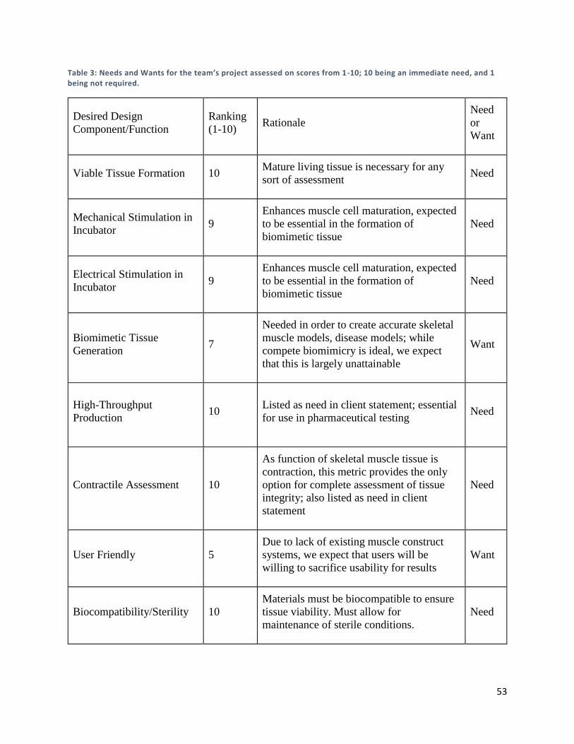
1 High-Throughput Maturation of Engineered Human Skeletal Muscle Tissue A Major Qualifying Project Submitted to the Faculty of Worcester Polytechnic Institute in partial fulfillment of the requirements for the Degree in Bachelor of Science in Biomedical Engineering By __________________________________ Benjamin Cossette __________________________________ Annabella Goncalves __________________________________ Alexander Marry __________________________________ Mina William Date: 4/24/17 Project Advisors: __________________________________ Professor Raymond Page, Advisor This report represents work of WPI undergraduate students submitted to the faculty as evidence of a degree requirement. WPI routinely publishes these reports on its web site without editorial or peer review. For more information about the projects program at WPI, see http://www.wpi.edu/Academics/Projects.
Transcript
1
High-Throughput Maturation of Engineered
Human Skeletal Muscle Tissue A Major Qualifying Project
Submitted to the Faculty of
Worcester Polytechnic Institute
in partial fulfillment of the requirements for the
Degree in Bachelor of Science
in
Biomedical Engineering
By
__________________________________
Benjamin Cossette
__________________________________
Annabella Goncalves
__________________________________
Alexander Marry
__________________________________
Mina William
Date: 4/24/17
Project Advisors:
__________________________________
Professor Raymond Page, Advisor
This report represents work of WPI undergraduate students submitted to the faculty as evidence of a
degree requirement. WPI routinely publishes these reports on its web site without editorial or peer
review. For more information about the projects program at WPI, see
Table of Contents Table of Figures ............................................................................................................................................. 5
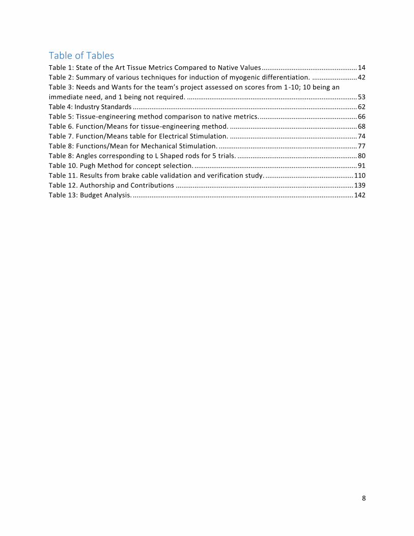
Table of Tables .............................................................................................................................................. 8
5.4 Final Experiment ................................................................................................................................. 112
Chapter 6: Final Design and Validation ..................................................................................................... 116
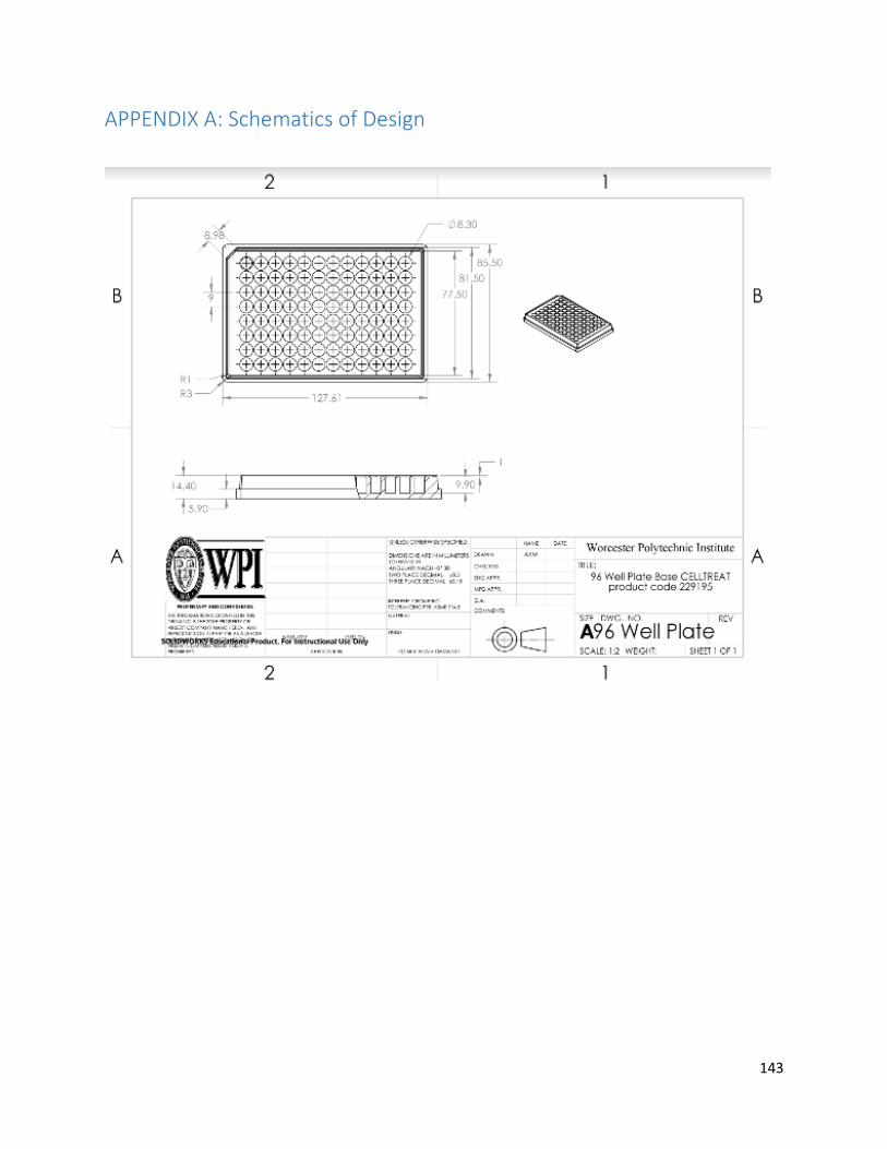
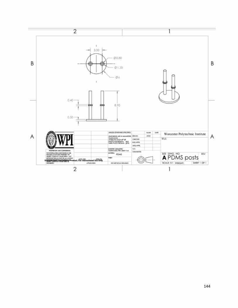
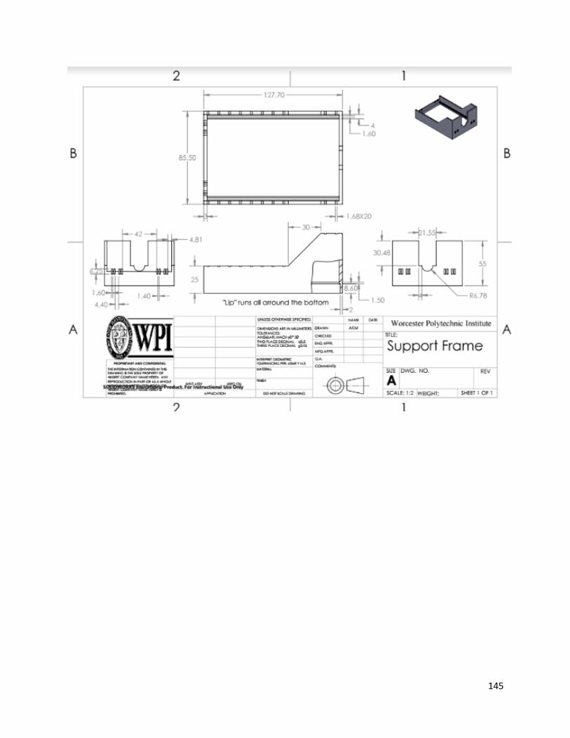
APPENDIX A: Schematics of Design ........................................................................................................... 143
5
Table of Figures Figure 1. Diagram of a skeletal muscle, highlighting its anatomical components, derived from tendons
anchored to bone. Shows the three connective tissue layers [8]. ............................................................. 17
Figure 2. A depiction of the walk-through starting from a muscle group, reaching to the sarcomeres in
the myofibrils [8]. ........................................................................................................................................ 18
Figure 3. Mechanical components of a sarcomeres unit; highlighting the cross -bridging that induces
Figure 12: Representative image showing mBAMS mounted on PDMS posts within a 96-well plate [27] 36
Figure 13: A: Representative image of a delaminating monolayer. B: Representative image of a rolled-up
delaminated monolayer, remaining anchored to lamanin-coated suture anchors. C: Cross-section of a
construct, showing similar structure to native muscle [30]. ...................................................................... 38
Figure 14: Representative cross-section of a self-assembled tissue-ring from the Page Lab. Black staining
is for myosin [32]. ....................................................................................................................................... 40
Figure 15: A: Representative image of Dennis’s electrical stimulation platform in an incubator. B:
Representative image of the electrode configuration with a 6-well plate [37]. ........................................ 44
Figure 16: IonOptix C-Pace EP prgrammable multi-channel power source and 6-well electrode plate lid
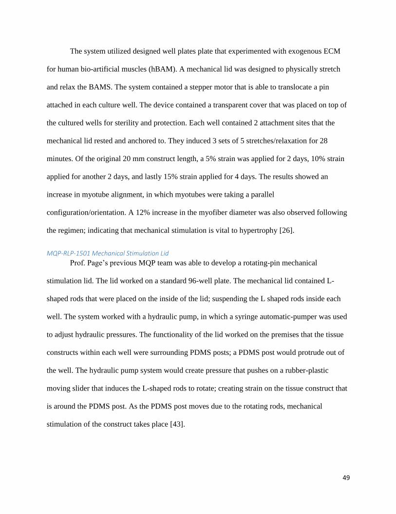
Figure 19. The designed hydraulic system that controls a mechanical stimulating lid; rotating L-shaped
rods to induce mechanical stimulation [43]. .............................................................................................. 50
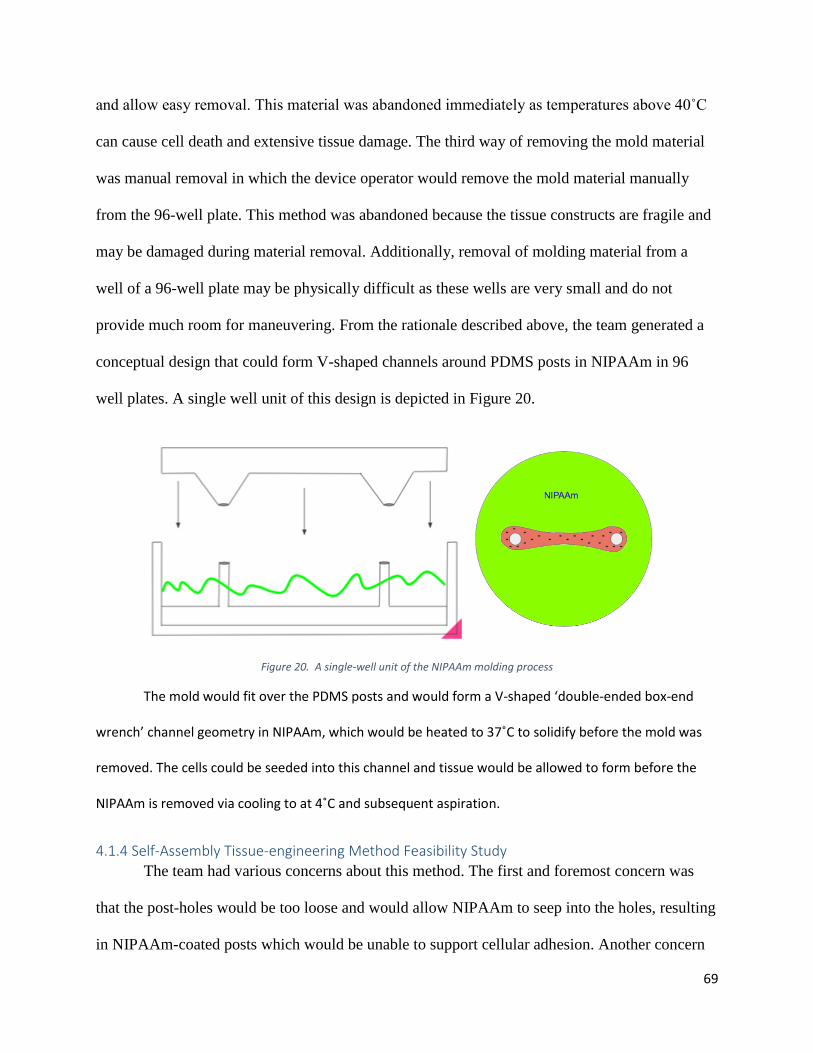
Figure 20. A single-well unit of the NIPAAm molding process ................................................................... 69
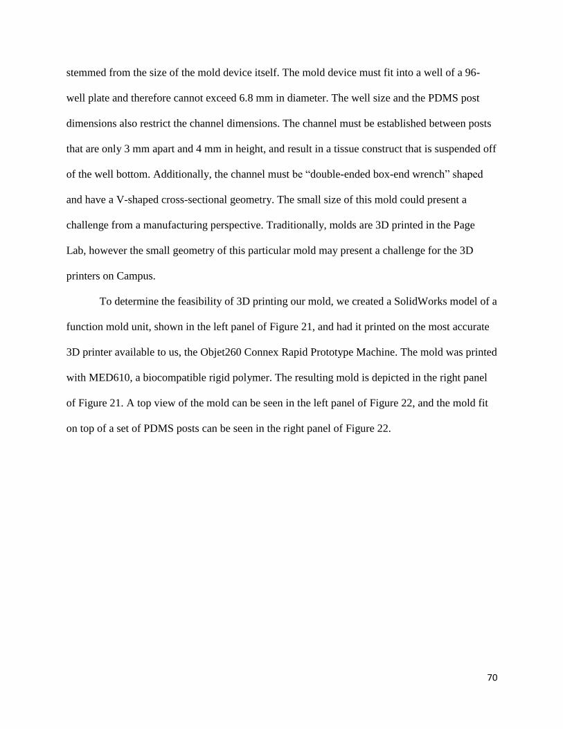
Figure 21. Left panel: CAD model of V-shaped NIPAAm mold. Right panel: image of 3D printed mold. ... 71
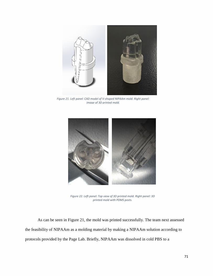
Figure 22. Left panel: Top view of 3D printed mold. Right panel: 3D printed mold with PDMS posts. ..... 71
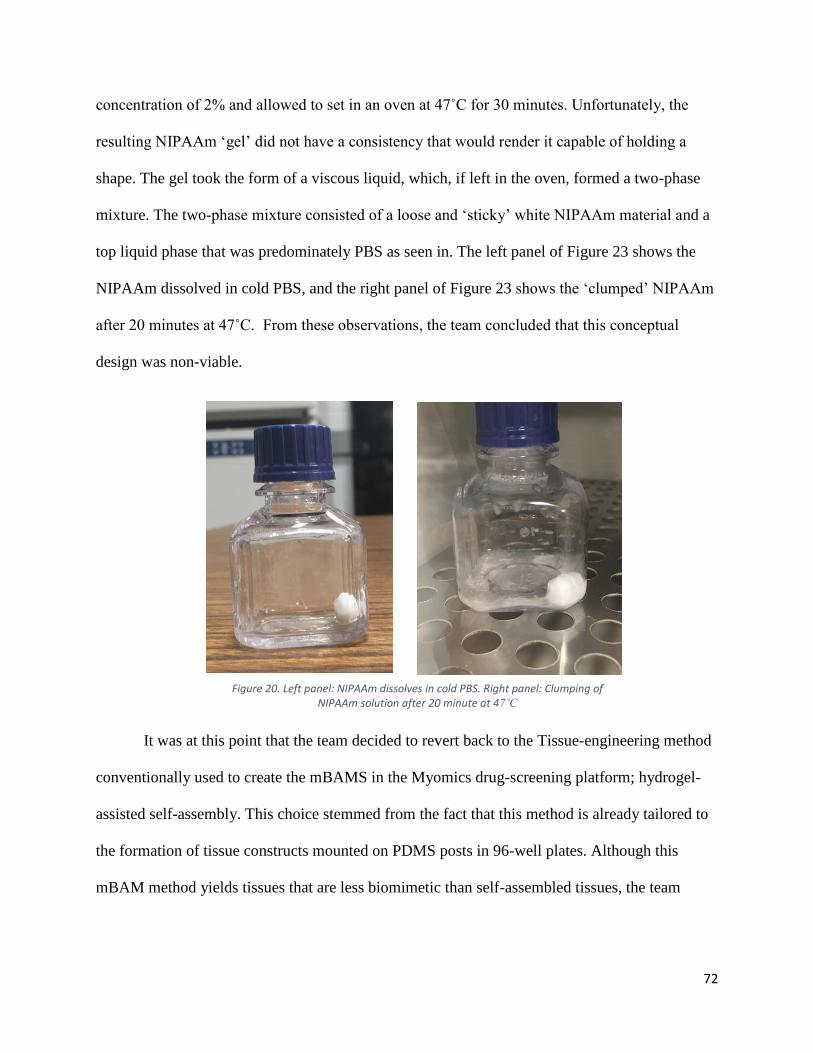
Figure 20. Left panel: NIPAAm dissolves in cold PBS. Right panel: Clumping of NIPAAm solution after 20
minute at 47˚C ............................................................................................................................................ 72
Figure 24: MQP-RLP-1501 Electrical Stimulation Lid .................................................................................. 75
6
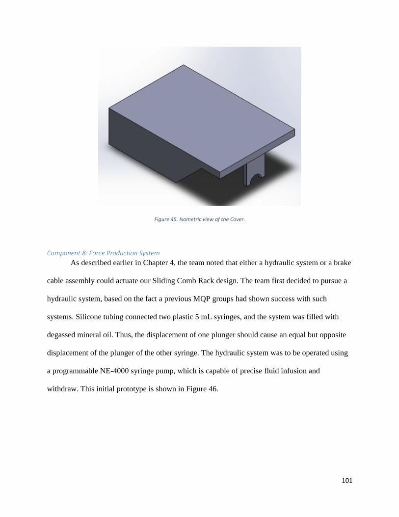
Figure 25. On the left is the top part of the mechanical lids; acting as a cover for the system. Center
image shows the hydraulic system and lid assembly. Right image sows the completely assembled device.
Acknowledgements The authors would like to sincerely thank the volunteers that made this project possible:
Professor Raymond Page (MQP Advisor), Jason Forte (WPI Graduate Student), Lisa Wall and
Elyse Favreau (Lab Managers), and Tom Partington (WPI Machinist). The team would also like
to acknowledge
10
Abstract With 95% of pharmaceutical drug candidates failing to make the transition from the
preclinical to clinical phase, the need for predictive disease models is ever rising.
Musculoskeletal diseases like Duchenne Muscular Dystrophy especially lack effective treatment
options, primarily due to the lack of predictive in-vivo animal models. Tissue-engineered human
skeletal muscle constructs could provide advantages over these traditional animal models. These
engineered models would ideally offer small functional units of biomimetic skeletal muscle
tissue for high-throughput drug screening and may circumnavigate the non-predictive nature of
most traditional preclinical model systems. However, current methods of skeletal muscle tissue
engineering yield immature tissues that lack biomimicry to native tissue. Tissue maturation
strategies such as mechanical and electrical stimulation have been employed in an effort to
improve biomimicry, and have been demonstrated to improve myofiber alignment, protein
expression, and contractile ability. In this MQP, a device was designed to both mechanically and
electrically stimulate hydrogel-assisted self-assembled skeletal muscle constructs in a high-
throughput manner.
11
Chapter 1: Introduction Over the years, the medical field has struggled with the treatment of muscular diseases,
largely due to the fact that there are no appropriately predictive disease models. Researchers
have long utilized pharmaceutical drugs as means to treat diseases. Before a drug is issued,
rigorous testing must take place. The pharmaceutical drug development process begins with
initial drug discovery from large-scale drug screening. Once promising compounds are
identified, pre-clinical research begins with in-vitro and in-vivo testing. Typically, compounds
are used to treat in-vitro cell models of the disease in a hope to elucidate treatment efficacy,
mechanism of action, and cytotoxicity. If a drug shows promise during in-vitro testing, the
compound is next tested in an animal disease model. Only after success in an in-vivo animal
disease model can the drug advance to clinical trials in humans. It is at this transition from
preclinical studies to clinical studies that 95% of drug candidates fail. The prevalence of drug
rejection can largely be attributed to the trend for drug candidates to show promise in the
preclinical in-vitro cell models and in-vivo animal models, but subsequently fail in human
clinical trials. Simply put, animal disease models are poorly predictive of human outcomes [1].
Pharmaceutical spending has skyrocketed to over 5 billion dollars per viable drug due to this
inadequacy of animal disease models.
Take for example Duchenne and Becker’s muscular dystrophy (DBMD), similar diseases
that affect 1 in 3,500 newborns [2]. Both diseases are characterized by a deficiency in
dystrophin, a protein that assists in muscle function. This deficiency manifests in progressive
muscle weakness, loss of regenerative capability, and ultimately death due to cardiac or
respiratory malfunction typically after 20-30 years of life. DBMD is one of the most prevalent
orphan diseases and thus is an area of substantial drug development spending [2]. For thirty
years, preclinical testing for DBMD drug candidates has been primarily conducted in the mdx
12
mouse model. The mdx model has a mutation in the dystrophin gene that manifests in a
premature stop codon on exon 23; halting translation of the protein and ultimately leading to a
disease phenotype similar to human DBMD. However, the mdx mouse model does not perfectly
recapitulate the severity and progression of the human diseases [3]. In January of 2016, a
promising drug from Biomarin Pharmaceutical was rejected by the FDA due to poor efficacy in
human trials. This type of situation is all too familiar within the field of muscle-disease drug
development and of drug development as a whole, and a vital need for more reliable model
systems is emerging [3].
Tissue-engineered in-vitro (outside of the body) human skeletal muscle models could
provide a variety of advantages over standard mouse models for muscle-associated diseases such
as DBMD. These models would ideally offer small functional units of human skeletal muscle for
high-throughput drug screening and may circumnavigate the issues associated with the non-
predictive nature of animal models for human diseases, such as needless spending due to the high
failure rate of drugs during the pre-clinical to clinical transition. The models would ideally be
completely biomimetic, meaning they would precisely recapitulate all aspects of the native
tissue.
A small bench-top model of skeletal muscle would likely take the form of a single
fascicle and would be composed of densely packed, aligned myocytes surrounded by the proper
ECM, as seen in Figure 2. These high-order features must be recapitulated in a biomimetic
model of human skeletal muscle, a feat that has not yet been achieved.
Much work has been invested into the development of bench top in-vitro skeletal muscle
models and a variety of approaches have emerged [4,5,6]. These approaches can be categorized
into three broad methods: hydrogel/mold systems, hydrogel-assisted self-assembly systems, and
13
monolayer delamination systems. The first type of system, hydrogel/mold systems, relies on the
suspension of precursor cells in a non-native mix of gelatinous protein, such as collagen, that
forms a rigid hydrogel. The cell/gel mixture is cast into a small mold in which the precursor cells
differentiate to form myotubes. The second type of system, hydrogel-assisted self-assembly,
relies on the seeding of precursor cells into a hydrogel, such as fibrin or collagen. This cell/gel
mixture is cast into a circular tissue culture well with anchors, and as the tissue matures, it
digests and remodels the hydrogel, forming a tissue construct composed of myotubes. The third
system, monolayer-delamination, relies on the formation of a confluent single-cell layer of
myotubes on the bottom of a culture plate. When two “tissue-anchors” are placed on top of the
monolayer, the cell sheet rolls up to form a dense construct of myotubes. Despite significant
research and development, none of these systems have been successful in producing biomimetic
human skeletal muscle tissues because the in-vitro tissues differ significantly from native tissue
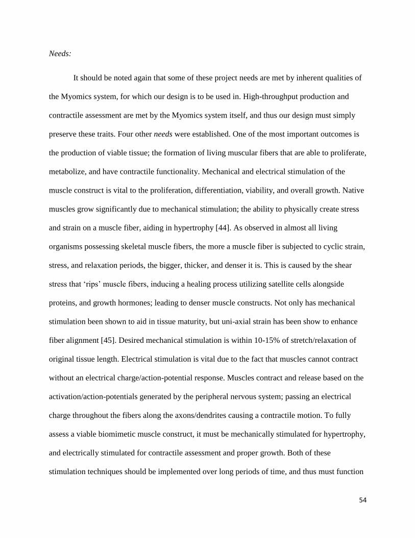
in a variety of ways. Some major areas of poor native recapitulation are highlighted in Table 1
below.
14
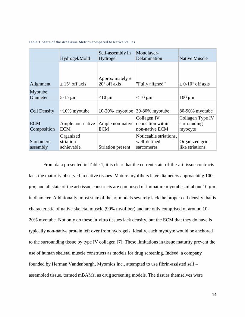
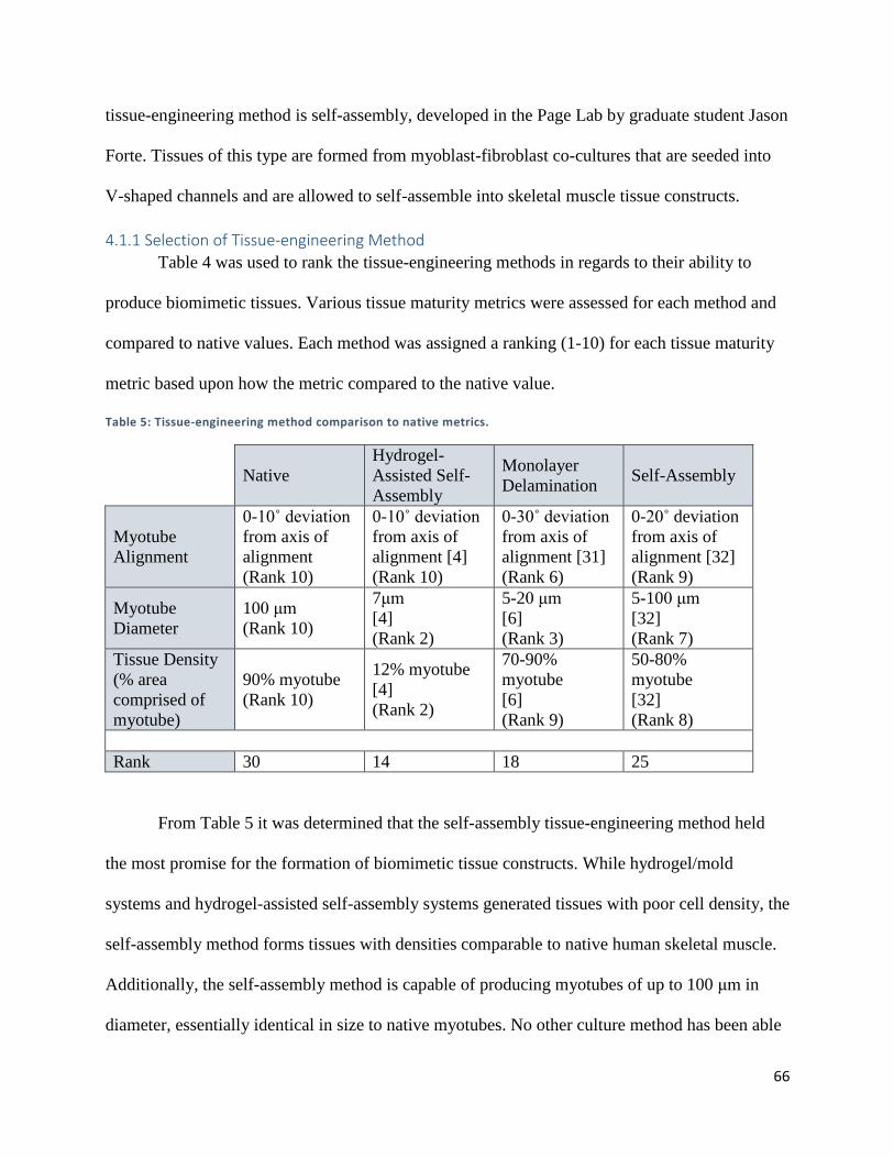
Table 1: State of the Art Tissue Metrics Compared to Native Values
Hydrogel/Mold
Self-assembly in
Hydrogel
Monolayer-
Delamination Native Muscle
Alignment ± 15° off axis
Approximately ±
20° off axis "Fully aligned” ± 0-10° off axis
Myotube
Diameter 5-15 μm <10 μm < 10 μm 100 μm
Cell Density ~10% myotube 10-20% myotube 30-80% myotube 80-90% myotube
ECM
Composition
Ample non-native
ECM
Ample non-native
ECM
Collagen IV
deposition within
non-native ECM
Collagen Type IV
surrounding
myocyte
Sarcomere
assembly
Organized
striation
achievable Striation present
Noticeable striations,
well-defined
sarcomeres
Organized grid-
like striations
From data presented in Table 1, it is clear that the current state-of-the-art tissue contracts
lack the maturity observed in native tissues. Mature myofibers have diameters approaching 100
μm, and all state of the art tissue constructs are composed of immature myotubes of about 10 μm
in diameter. Additionally, most state of the art models severely lack the proper cell density that is
characteristic of native skeletal muscle (90% myofiber) and are only comprised of around 10-
20% myotube. Not only do these in-vitro tissues lack density, but the ECM that they do have is
typically non-native protein left over from hydrogels. Ideally, each myocyte would be anchored
to the surrounding tissue by type IV collagen [7]. These limitations in tissue maturity prevent the
use of human skeletal muscle constructs as models for drug screening. Indeed, a company
founded by Herman Vandenburgh, Myomics Inc., attempted to use fibrin-assisted self –
assembled tissue, termed mBAMs, as drug screening models. The tissues themselves were
15
created in 96-well plates and were anchored to two flexible PDMS posts, allowing for contractile
assessment via post-deflection upon tetanic contraction. Unfortunately, the lack of tissue
maturity caused potential pharmaceutical clients to become hesitant to adopt the drug-screening
technology resulting in company failure. Simply put, the Myomics drug-screening platform had
all the makings of a successful technology, save for the tissue themselves. The fate of Myomics
Inc. highlights the need for skeletal muscle constructs that exhibit increased tissue maturity, and
that are ultimately more biomimetic than existing models.
To meet the needs described above, the team planned to design an in-vitro tissue-
engineering system capable of producing human skeletal muscle tissue. As current tissue-
engineered skeletal muscle tissue does not resemble native tissue closely enough to serve as an
accurate model, the primary goal of the project is to produce tissues that are more biomimetic
than those produced by current approaches. These tissues are to ultimately serve as disease
models for pharmaceutical testing, and thus a secondary goal of the project is to design the
tissue-engineering system in a way that allows for high-throughput production and testing.
16
Chapter 2: Background Research This chapter details the background research the team conducted to better understand the
project. It contains information pertaining to muscle anatomy and physiology, clinical
significance of the current project, current approaches to the tissue-engineering of in-vitro
skeletal muscle tissue, as well as current strategies for tissue maturity enhancement.
2.1 Skeletal Muscle Anatomy Skeletal muscles are the basis of structure and function of the human body. Most skeletal
muscles attach to two bones: origin and insertion. Skeletal muscles are attached to bones by
tendons; strong connective tissue bands. Structurally, they aid with posture, organ protection,
shape, strength, and overall mechanical stability. Their most important function is the voluntary
action; allowing translocation and movement. This is derived from their ability to produce
contractions and relaxations that forces muscle fibers to shorten and lengthen.
2.1.1 Skeletal Muscle Structure
In 3D space, skeletal muscles are surrounded and wrapped in collagen, an extracellular
structural protein for connective tissue. Tendons are composed of collagen, which attaches
muscle fibers to bone. Skeletal muscle cells are long and slender. Their thickness varies from 10-
60μm in diameter. Their length ranges from 1mm-30cm. A skeletal muscle cell can be comprised
of multiple fibers, termed bundles. The bundles are sheathed in connective tissue layers for
protection and support. The muscle fibers are multinucleated and are surrounded by the
sarcolemma; an electrically polarized membrane. The nuclei is located under the sarcolemma. A
fasciculus is a bundle of muscle fibers which is surrounded by the perimysium; a strong
connective tissue sheath. Each muscle fiber within the fasciculus is then surrounded by the
endomysium sheath. The epimysium is the connective tissue sheath that covers each entire
muscle; it is tough, protective, and emerges from tendons that are attached to bone. The fascia is
17
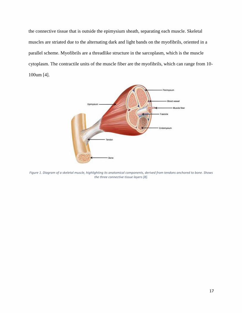
the connective tissue that is outside the epimysium sheath, separating each muscle. Skeletal
muscles are striated due to the alternating dark and light bands on the myofibrils, oriented in a
parallel scheme. Myofibrils are a threadlike structure in the sarcoplasm, which is the muscle
cytoplasm. The contractile units of the muscle fiber are the myofibrils, which can range from 10-
100um [4].
Figure 1. Diagram of a skeletal muscle, highlighting its anatomical components, derived from tendons anchored to bone. Shows the three connective tissue layers [8].
18
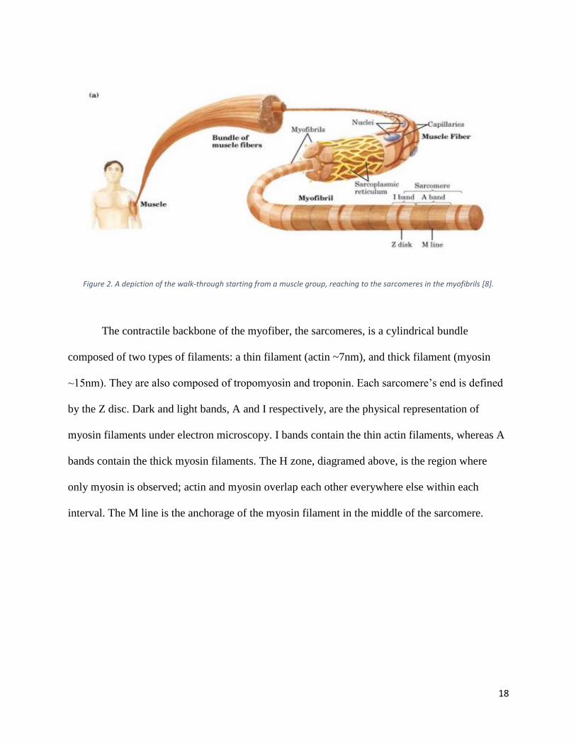
Figure 2. A depiction of the walk-through starting from a muscle group, reaching to the sarcomeres in the myofibrils [8].
The contractile backbone of the myofiber, the sarcomeres, is a cylindrical bundle
composed of two types of filaments: a thin filament (actin ~7nm), and thick filament (myosin
~15nm). They are also composed of tropomyosin and troponin. Each sarcomere’s end is defined
by the Z disc. Dark and light bands, A and I respectively, are the physical representation of
myosin filaments under electron microscopy. I bands contain the thin actin filaments, whereas A
bands contain the thick myosin filaments. The H zone, diagramed above, is the region where
only myosin is observed; actin and myosin overlap each other everywhere else within each
interval. The M line is the anchorage of the myosin filament in the middle of the sarcomere.
19
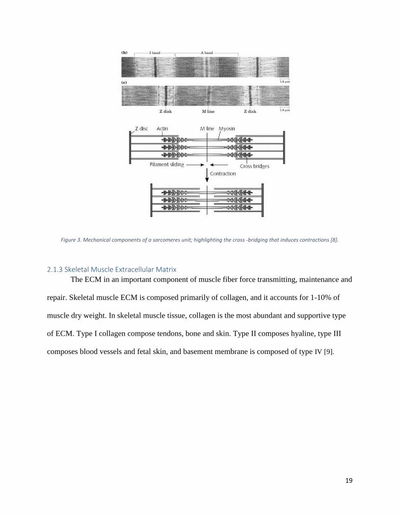
Figure 3. Mechanical components of a sarcomeres unit; highlighting the cross -bridging that induces contractions [8].
2.1.3 Skeletal Muscle Extracellular Matrix
The ECM in an important component of muscle fiber force transmitting, maintenance and
repair. Skeletal muscle ECM is composed primarily of collagen, and it accounts for 1-10% of
muscle dry weight. In skeletal muscle tissue, collagen is the most abundant and supportive type
of ECM. Type I collagen compose tendons, bone and skin. Type II composes hyaline, type III
composes blood vessels and fetal skin, and basement membrane is composed of type IV [9].
20
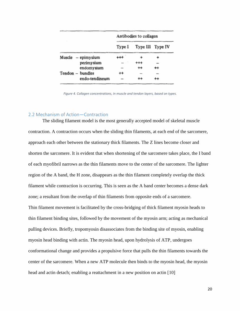
Figure 4. Collagen concentrations, in muscle and tendon layers, based on types.
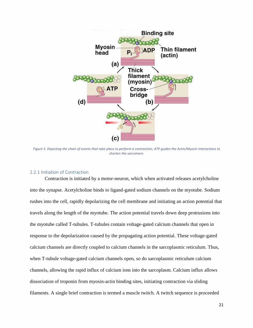
2.2 Mechanism of Action—Contraction The sliding filament model is the most generally accepted model of skeletal muscle
contraction. A contraction occurs when the sliding thin filaments, at each end of the sarcomere,
approach each other between the stationary thick filaments. The Z lines become closer and
shorten the sarcomere. It is evident that when shortening of the sarcomere takes place, the I band
of each myofibril narrows as the thin filaments move to the center of the sarcomere. The lighter
region of the A band, the H zone, disappears as the thin filament completely overlap the thick
filament while contraction is occurring. This is seen as the A band center becomes a dense dark
zone; a resultant from the overlap of thin filaments from opposite ends of a sarcomere.
Thin filament movement is facilitated by the cross-bridging of thick filament myosin heads to
thin filament binding sites, followed by the movement of the myosin arm; acting as mechanical
pulling devices. Briefly, tropomyosin disassociates from the binding site of myosin, enabling
myosin head binding with actin. The myosin head, upon hydrolysis of ATP, undergoes
conformational change and provides a propulsive force that pulls the thin filaments towards the
center of the sarcomere. When a new ATP molecule then binds to the myosin head, the myosin
head and actin detach; enabling a reattachment in a new position on actin [10]
21
Figure 5. Depicting the chain of events that take place to perform a contraction; ATP guides the Actin/Myosin interactions to shorten the sarcomere.
2.2.1 Initiation of Contraction
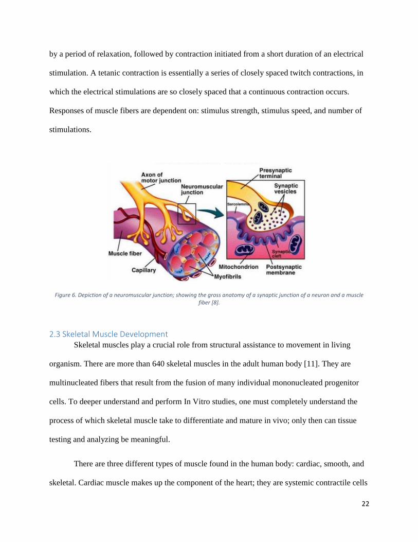
Contraction is initiated by a motor-neuron, which when activated releases acetylcholine
into the synapse. Acetylcholine binds to ligand-gated sodium channels on the myotube. Sodium
rushes into the cell, rapidly depolarizing the cell membrane and initiating an action potential that
travels along the length of the myotube. The action potential travels down deep protrusions into
the myotube called T-tubules. T-tubules contain voltage-gated calcium channels that open in
response to the depolarization caused by the propagating action potential. These voltage-gated
calcium channels are directly coupled to calcium channels in the sarcoplasmic reticulum. Thus,
when T-tubule voltage-gated calcium channels open, so do sarcoplasmic reticulum calcium
channels, allowing the rapid influx of calcium ions into the sarcoplasm. Calcium influx allows
dissociation of troponin from myosin-actin binding sites, initiating contraction via sliding
filaments. A single brief contraction is termed a muscle twitch. A twitch sequence is proceeded
22
by a period of relaxation, followed by contraction initiated from a short duration of an electrical
stimulation. A tetanic contraction is essentially a series of closely spaced twitch contractions, in
which the electrical stimulations are so closely spaced that a continuous contraction occurs.
Responses of muscle fibers are dependent on: stimulus strength, stimulus speed, and number of
stimulations.
Figure 6. Depiction of a neuromuscular junction; showing the gross anatomy of a synaptic junction of a neuron and a muscle fiber [8].
2.3 Skeletal Muscle Development Skeletal muscles play a crucial role from structural assistance to movement in living
organism. There are more than 640 skeletal muscles in the adult human body [11]. They are
multinucleated fibers that result from the fusion of many individual mononucleated progenitor
cells. To deeper understand and perform In Vitro studies, one must completely understand the
process of which skeletal muscle take to differentiate and mature in vivo; only then can tissue
testing and analyzing be meaningful.
There are three different types of muscle found in the human body: cardiac, smooth, and
skeletal. Cardiac muscle makes up the component of the heart; they are systemic contractile cells
23
able to generate a magnitude of force to pump blood throughout the circulatory system. They are
involuntary and highly striated. Smooth muscles are muscle cells that surround and line the
organs in the human body, for example the stomach, and blood vessels. Smooth muscles are
involuntary, and aid in the movement of substances across the body. Skeletal muscles are the
most abundant, and carryout all movement and support by binding to the exoskeleton. They are
voluntary muscle cells that derive their mobility from somatic cerebrospinal nerves.
2.3.1 Skeletal Muscle Somitogenesis
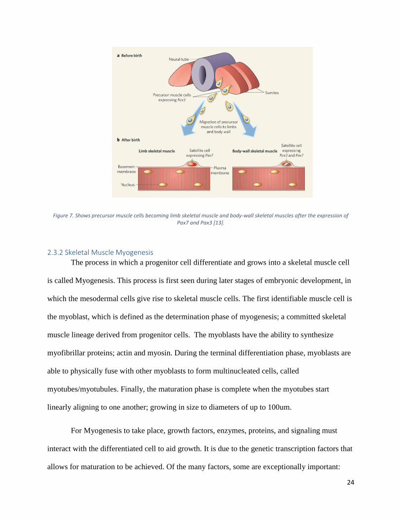
During gestation, cells will begin to position and differentiate from the three germ layers
that develop: the ectoderm, mesoderm, and endoderm. Mesoderms, after introduction of
morphogen gradients, are induced to become somites; the first metameric structures in
mammalian embryos. After somites leave the caudal region of the mesoderm, the cyclic
expression of genes ceases, and retinoic acid increases; establishing polarity in the somite. From
this polarized somite, the mesenchymal sclerotome forms from the most ventral part; the
precursor to cartilage and bone. Skeletal muscle are derived of the structures that form from the
most dorsal portion of the somite; which remain epithelial and becomes dermomyotome. From
those dermomyotomes, the lips will mature to become myotome; the primitive muscle structure
that contains the committed muscle cells [12]. Those muscle cells express high levels of MyoD
and Myf5. Those expressions are the markers of terminal specification to the muscle lineage. For
mature skeletal muscle cells to form, they must further differentiate; a process where a cell
adapts a specific structure and function aided by specific growth factors, receptors, and
transcription factors [13].
24
Figure 7. Shows precursor muscle cells becoming limb skeletal muscle and body-wall skeletal muscles after the expression of Pax7 and Pax3 [13].
2.3.2 Skeletal Muscle Myogenesis
The process in which a progenitor cell differentiate and grows into a skeletal muscle cell
is called Myogenesis. This process is first seen during later stages of embryonic development, in
which the mesodermal cells give rise to skeletal muscle cells. The first identifiable muscle cell is
the myoblast, which is defined as the determination phase of myogenesis; a committed skeletal
muscle lineage derived from progenitor cells. The myoblasts have the ability to synthesize
myofibrillar proteins; actin and myosin. During the terminal differentiation phase, myoblasts are
able to physically fuse with other myoblasts to form multinucleated cells, called
myotubes/myotubules. Finally, the maturation phase is complete when the myotubes start
linearly aligning to one another; growing in size to diameters of up to 100um.
For Myogenesis to take place, growth factors, enzymes, proteins, and signaling must
interact with the differentiated cell to aid growth. It is due to the genetic transcription factors that
allows for maturation to be achieved. Of the many factors, some are exceptionally important:
25
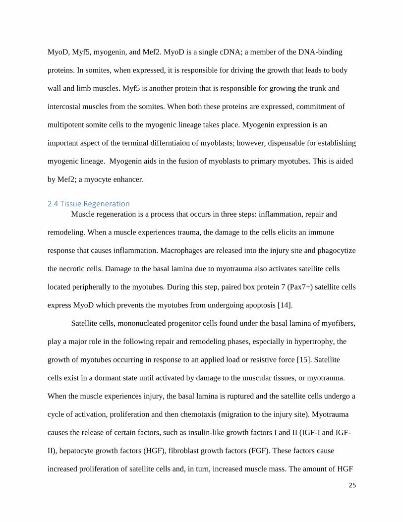
MyoD, Myf5, myogenin, and Mef2. MyoD is a single cDNA; a member of the DNA-binding
proteins. In somites, when expressed, it is responsible for driving the growth that leads to body
wall and limb muscles. Myf5 is another protein that is responsible for growing the trunk and
intercostal muscles from the somites. When both these proteins are expressed, commitment of
multipotent somite cells to the myogenic lineage takes place. Myogenin expression is an
important aspect of the terminal differntiaion of myoblasts; however, dispensable for establishing
myogenic lineage. Myogenin aids in the fusion of myoblasts to primary myotubes. This is aided
by Mef2; a myocyte enhancer.
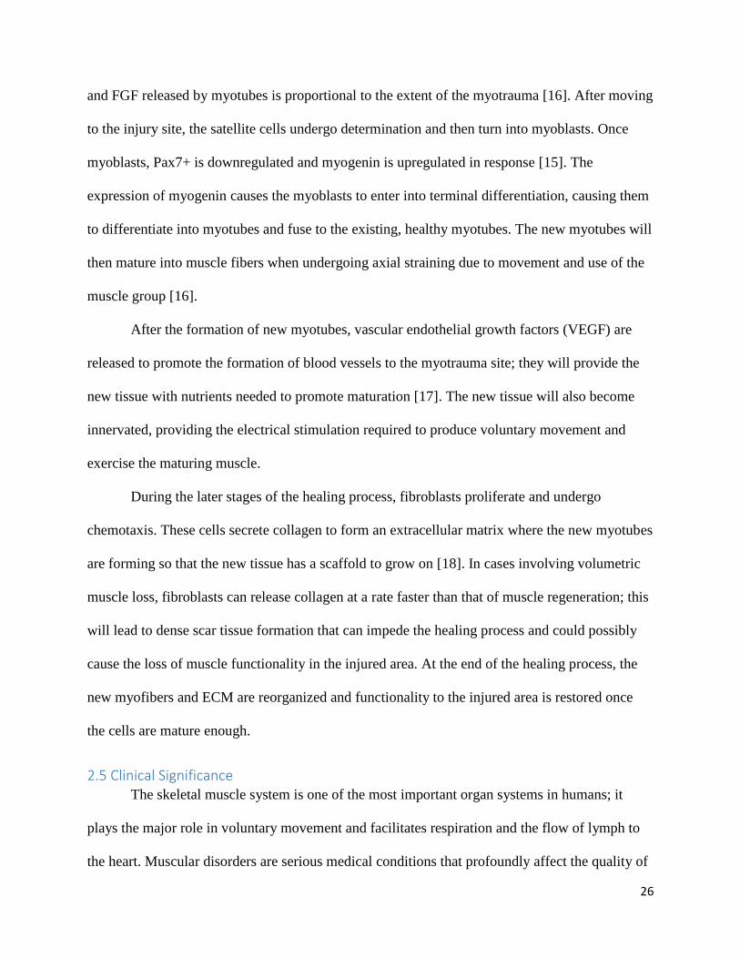
2.4 Tissue Regeneration Muscle regeneration is a process that occurs in three steps: inflammation, repair and
remodeling. When a muscle experiences trauma, the damage to the cells elicits an immune
response that causes inflammation. Macrophages are released into the injury site and phagocytize
the necrotic cells. Damage to the basal lamina due to myotrauma also activates satellite cells
located peripherally to the myotubes. During this step, paired box protein 7 (Pax7+) satellite cells
express MyoD which prevents the myotubes from undergoing apoptosis [14].
Satellite cells, mononucleated progenitor cells found under the basal lamina of myofibers,
play a major role in the following repair and remodeling phases, especially in hypertrophy, the
growth of myotubes occurring in response to an applied load or resistive force [15]. Satellite
cells exist in a dormant state until activated by damage to the muscular tissues, or myotrauma.
When the muscle experiences injury, the basal lamina is ruptured and the satellite cells undergo a
cycle of activation, proliferation and then chemotaxis (migration to the injury site). Myotrauma
causes the release of certain factors, such as insulin-like growth factors I and II (IGF-I and IGF-
II), hepatocyte growth factors (HGF), fibroblast growth factors (FGF). These factors cause
increased proliferation of satellite cells and, in turn, increased muscle mass. The amount of HGF
26
and FGF released by myotubes is proportional to the extent of the myotrauma [16]. After moving
to the injury site, the satellite cells undergo determination and then turn into myoblasts. Once
myoblasts, Pax7+ is downregulated and myogenin is upregulated in response [15]. The
expression of myogenin causes the myoblasts to enter into terminal differentiation, causing them
to differentiate into myotubes and fuse to the existing, healthy myotubes. The new myotubes will
then mature into muscle fibers when undergoing axial straining due to movement and use of the
muscle group [16].
After the formation of new myotubes, vascular endothelial growth factors (VEGF) are
released to promote the formation of blood vessels to the myotrauma site; they will provide the
new tissue with nutrients needed to promote maturation [17]. The new tissue will also become
innervated, providing the electrical stimulation required to produce voluntary movement and
exercise the maturing muscle.
During the later stages of the healing process, fibroblasts proliferate and undergo
chemotaxis. These cells secrete collagen to form an extracellular matrix where the new myotubes
are forming so that the new tissue has a scaffold to grow on [18]. In cases involving volumetric
muscle loss, fibroblasts can release collagen at a rate faster than that of muscle regeneration; this
will lead to dense scar tissue formation that can impede the healing process and could possibly
cause the loss of muscle functionality in the injured area. At the end of the healing process, the
new myofibers and ECM are reorganized and functionality to the injured area is restored once
the cells are mature enough.
2.5 Clinical Significance The skeletal muscle system is one of the most important organ systems in humans; it
plays the major role in voluntary movement and facilitates respiration and the flow of lymph to
the heart. Muscular disorders are serious medical conditions that profoundly affect the quality of
27
life of those afflicted; many have been known to leave patients paralyzed and with significantly
shorter life expectancies. Muscular dystrophies, such as Duchenne’s muscular dystrophy and
Becker’s muscular dystrophy, involve the progressive loss of muscle mass and function, leaving
patients paralyzed, in severe pain and completely dependent on others for their care. Atrophies
caused by disuse or stemming from neurogenic disorders also have similar effects and prognoses
as muscular dystrophies. Dystrophies and atrophies are difficult for physicians to treat; most
times doctors treat the symptoms since there has been little development for a complete cure.
The afflicted patients are typically provided these treatments for the rest of their lives,
accumulating expensive medical bills for their family members to pay. A tissue-engineered
skeletal muscle could provide an in vitro means for pharmaceutical companies to test drugs for
these disorders. These models would provide a cheaper, safer and more streamlined method for
drug testing that could possibly eliminate the need for expensive animal and human trials.
Skeletal muscle models could expedite the discovery of a cure for these disorders, giving those
suffering these diseases much longer, high quality lives.
Muscular dystrophy is a category of genetic muscular disease characterized by the
progressive deterioration of muscle mass. Although over thirty different variations currently
exist, the most commonly occurring are Duchenne’s muscular dystrophy (DMD) and Becker’s
muscular dystrophy (BMD) [19]. DMD is characterized by the deletion of the protein dystrophin,
normally found in the sarcolemma of skeletal muscle. Dystrophin is responsible for making
myofibers more mechanically stable in order to have smooth, coordinated voluntary movement.
DMD is typically found in males with symptoms manifesting within the first five years of life
[20]. The degradation of muscle occurs at an incredibly fast rate; most patients suffering from it
do not survive past their twenties. BMD is another variation of muscular dystrophy that is
28
extremely similar to DMD, characterized by decreasing dystrophin levels. The main differences
are that BMD progresses at a much slower rate and symptoms usually manifest first during
adolescence or early adulthood [19].
There currently exists no cure for any form of muscular dystrophy, only treatment to slow
its progress and alleviate its symptoms. Most patients afflicted with this disorder undergo
physical therapy in the attempt to preserve muscle strength and tone. Eventually, all those with
this disorder will lose their strength and will not be able to produce voluntary movement. Many
will have difficulty breathing since they are not able to properly use their intercostal muscles to
expand the thoracic cavity during inhalation, thus becoming dependent on respirators and
supplementary oxygen in order to breathe. Physicians may also prescribe steroids and/or
recommend surgery in order to treat the symptoms, however these interventions are only utilized
to extend life and increase quality of life [21].
Muscular atrophy is characterized by the degradation of muscle caused by its disuse.
Muscle atrophy most commonly occurs in bedridden patients who do not perform any voluntary
movement. Some instances of atrophy have neurogenic origins, in which the nervous system
cannot properly conduct action potentials to produce muscle contraction and thus movement
[22]. Other factors that can lead to disuse include level of activity, weight and age. Mature
muscles must undergo a minimum amount of force to maintain strength and tone. If muscles do
not experience the minimum force required, the body also cannot build muscle mass. Prolonged
disuse of muscles activates the Ub-proteasome pathway, which incites protein degradation within
the skeletal muscles. In this instance, the muscles will degrade at a much faster rate than they
will generate [23]. This will eventually lead to the loss of muscle stability and function, leading
to the loss of voluntary movement.
29
Volumetric muscle loss is the significant dissection of muscle due to trauma or medical
procedures. This significant muscle loss destabilizes the affected area, making voluntary
movement difficult to impossible. When the body senses the loss of a large volume of muscle,
rhabdomyolysis, the dissolution of skeletal muscle, takes place. The body will try to use the
satellite cells to repair the damaged area, but if the amount of muscle lost is significant then
fibroblasts will secrete high levels of collagen to form dense scar tissue [18]. Although the scar
tissue fills the area missing skeletal muscle, it cannot provide the same functionality as muscle.
Currently, there are no viable disease models for most musculoskeletal diseases. The
successful development of treatments for these diseases is contingent upon drug discovery,
requiring predictive disease models. In vitro models of human skeletal muscle could represent a
highly predictive disease modeling approach and may play a role in the pharmaceutical drug
discovery process. The United States Food and Drug Administration requires that a potential
drug to undergo a phased testing in order to determine its efficacy and biocompatibility. Phase 0
of testing involves no live test subjects, but Phases I through IV involve live animal and human
test subjects. Those used in testing may be subjected to the negative side effects from the
experiments. It also costs pharmaceutical companies millions of dollars to pay for the testing and
compensation for human subjects. Skeletal muscle constructs that are biomimetic of human
muscle can totally eliminate the need for animal testing and reduce the number of human
subjects required to test potential drugs. The constructs may be able to save pharmaceutical
companies millions of dollars and make the drug testing process more efficient and streamlined.
30
2.6 Tissue-engineering Of In Vitro Skeletal Muscle Many approaches have emerged in the creation of biomimetic in-vitro models of skeletal
muscle, which will be discussed in the next sections. First, various tissue-engineering methods
will be discussed, followed by a discussion on cell selection and differentiation techniques.
2.6.1 Tissue-engineering Approaches
Decades ago, scientists began to realize the limitations of cell/tissue biology research on
cells/tissues cultured on stiff two-dimensional surfaces [24]. Of particular difficulty was the
formation of muscle tissue in vitro. 2D cultures often detached from the culture surface resulting
in a free-floating monolayer that was difficult to maintain. In an attempt to combat these issues,
researchers began to culture muscle cells on top of collagen hydrogel matrixes. This allowed the
formation of neonatal-like myotubes, however these immature myotubes differed significantly
from their in-vivo counterparts. The myotubes often expressed very little myofibriallar protein
and were thus incapable of transition to adult-like mature muscle tissue [24].
Vandenburgh published a 1988 paper that described a new method for culturing primary
skeletal muscle cells that allowed for the formation of more biomimetic tissue. Primary avian
muscle biopsy cultures were suspended in a collagen matrix and set into circular molds
surrounded by a stainless steel anchoring-mesh. While 2D cultured tissues only showed lamina
formation at the cell-surface contacting site, these 3D cultured tissues in collagen allowed the
formation of a biomimetic basal lamina around the entire periphery of the cell. The mesh allowed
permanent tissue attachment, even after the construct detached from culture surface, thereby
maintaining tension within the tissue. Tissues cultured with this new 3D collagen method
showed increased protein expression and could maintain elevated levels for several weeks. This
method provided key benefits over traditional 2D culture systems and produced myotubes that
were more biomimetic than previously created. While the myotubes were still immature,
31
Vandenburgh’s work set a platform for 3D skeletal muscle tissue-engineering research for years
to come.
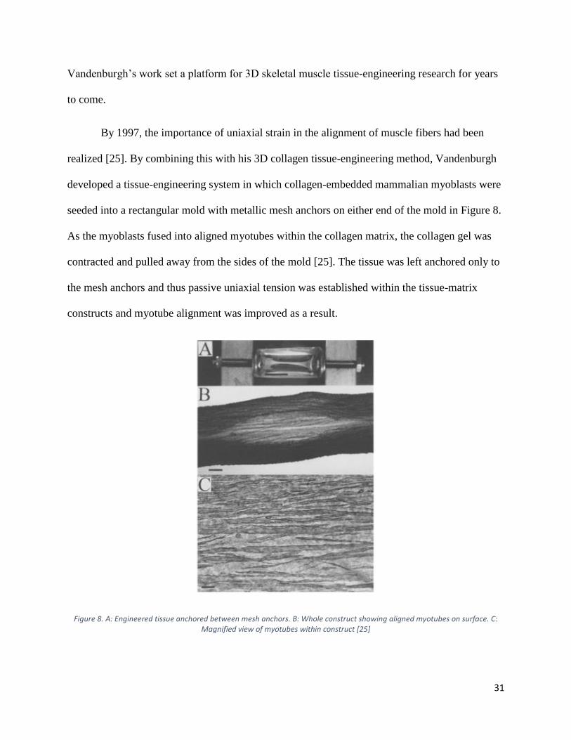
By 1997, the importance of uniaxial strain in the alignment of muscle fibers had been
realized [25]. By combining this with his 3D collagen tissue-engineering method, Vandenburgh
developed a tissue-engineering system in which collagen-embedded mammalian myoblasts were
seeded into a rectangular mold with metallic mesh anchors on either end of the mold in Figure 8.
As the myoblasts fused into aligned myotubes within the collagen matrix, the collagen gel was
contracted and pulled away from the sides of the mold [25]. The tissue was left anchored only to
the mesh anchors and thus passive uniaxial tension was established within the tissue-matrix
constructs and myotube alignment was improved as a result.
Figure 8. A: Engineered tissue anchored between mesh anchors. B: Whole construct showing aligned myotubes on surface. C: Magnified view of myotubes within construct [25]
32
By 2002, Vandenburgh and Powell had improved the 1997 collagen-assisted self-
assembly method to utilize human cells and had termed their contracts Human BioArtifical
Muscles (HBAMs) [26]. These constructs allowed for the formation of aligned human
myotubes, however the myotubes were still immature. The myotubes had low diameters (~5μm)
and only composed ~7% of the construct cross-sectional area (the rest was the non-native ECM
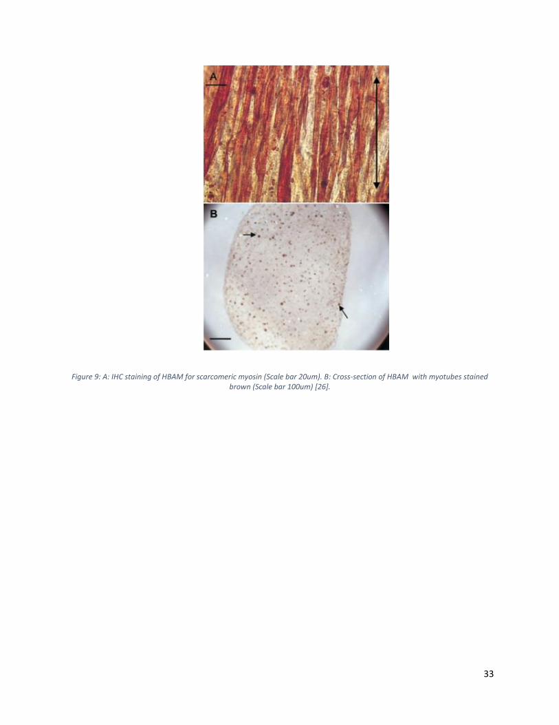
collagen/Matrigel matrix) in Figure 9. In their 2002 paper, Vandenburgh and Powell
incorporated mechanical stimulation into the tissue-engineering process in hopes to improve
maturity and biomimicry of the HBAMs. The tissues were mounted on two pins that were
connected to a uniaxial stepper motor and subjected to mechanical strain regimens. Mechanical
stimulation of the tissues resulted in improvements in both myotube diameter (12% improvement
from 6.4μmto 7.1um) as well as in myotube area percentage (40% improvement from 7.8% to
10.9%) [26]. However, when these values are compared to native tissue, the lack of biomimicry
is strikingly apparent.
33
Figure 9: A: IHC staining of HBAM for scarcomeric myosin (Scale bar 20um). B: Cross-section of HBAM with myotubes stained brown (Scale bar 100um) [26].
34
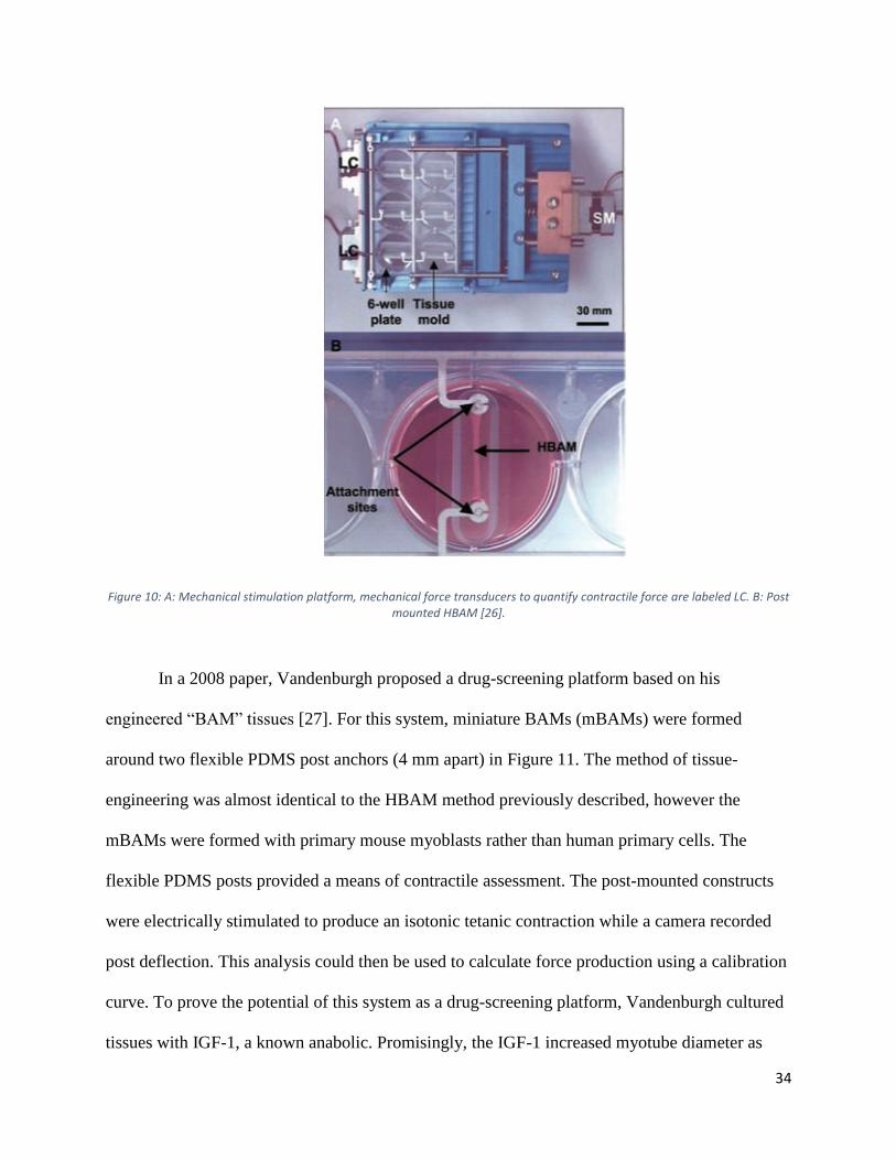
Figure 10: A: Mechanical stimulation platform, mechanical force transducers to quantify contractile force are labeled LC. B: Post mounted HBAM [26].
In a 2008 paper, Vandenburgh proposed a drug-screening platform based on his
engineered “BAM” tissues [27]. For this system, miniature BAMs (mBAMs) were formed
around two flexible PDMS post anchors (4 mm apart) in Figure 11. The method of tissue-
engineering was almost identical to the HBAM method previously described, however the
mBAMs were formed with primary mouse myoblasts rather than human primary cells. The
flexible PDMS posts provided a means of contractile assessment. The post-mounted constructs
were electrically stimulated to produce an isotonic tetanic contraction while a camera recorded
post deflection. This analysis could then be used to calculate force production using a calibration
curve. To prove the potential of this system as a drug-screening platform, Vandenburgh cultured
tissues with IGF-1, a known anabolic. Promisingly, the IGF-1 increased myotube diameter as
35
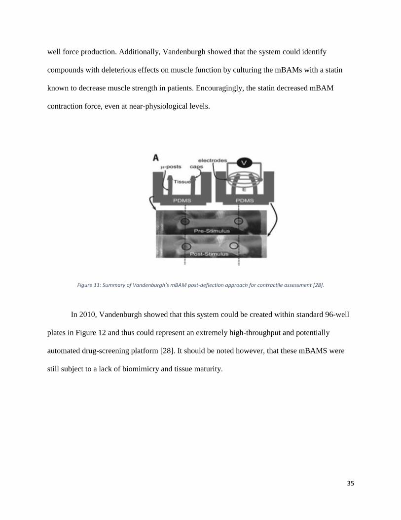
well force production. Additionally, Vandenburgh showed that the system could identify
compounds with deleterious effects on muscle function by culturing the mBAMs with a statin
known to decrease muscle strength in patients. Encouragingly, the statin decreased mBAM
contraction force, even at near-physiological levels.
Figure 11: Summary of Vandenburgh’s mBAM post-deflection approach for contractile assessment [28].
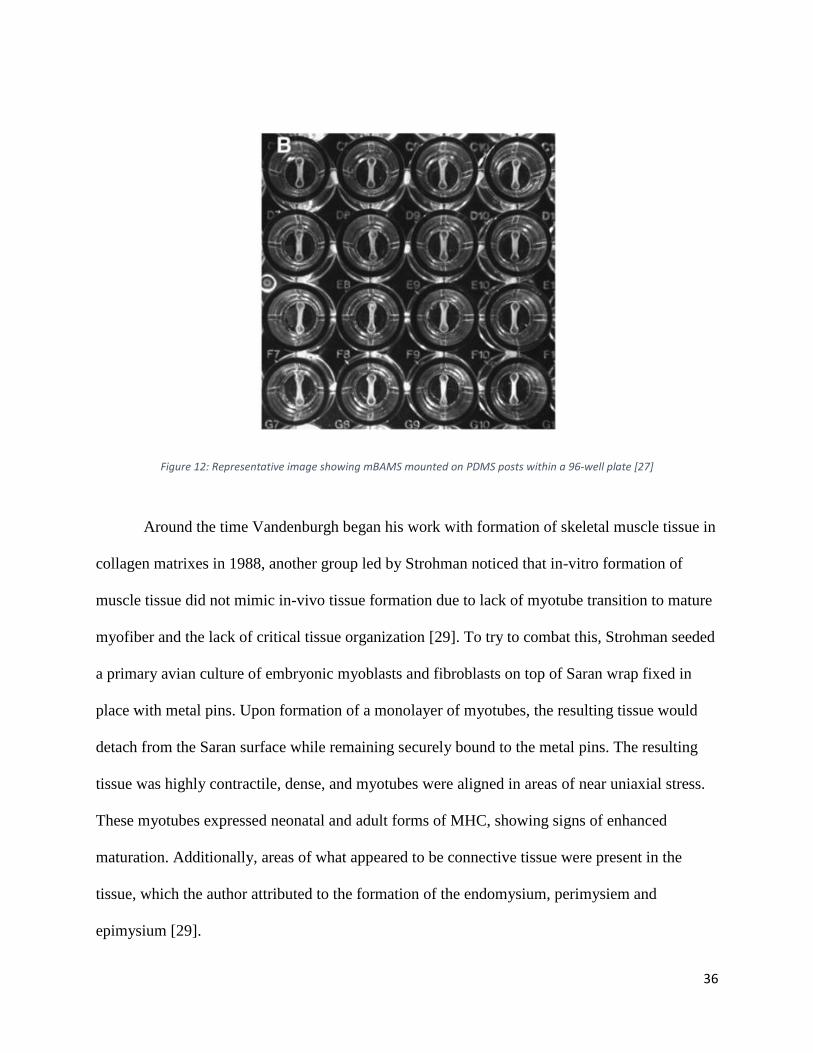
In 2010, Vandenburgh showed that this system could be created within standard 96-well
plates in Figure 12 and thus could represent an extremely high-throughput and potentially
automated drug-screening platform [28]. It should be noted however, that these mBAMS were
still subject to a lack of biomimicry and tissue maturity.
36
Figure 12: Representative image showing mBAMS mounted on PDMS posts within a 96-well plate [27]
Around the time Vandenburgh began his work with formation of skeletal muscle tissue in
collagen matrixes in 1988, another group led by Strohman noticed that in-vitro formation of
muscle tissue did not mimic in-vivo tissue formation due to lack of myotube transition to mature
myofiber and the lack of critical tissue organization [29]. To try to combat this, Strohman seeded
a primary avian culture of embryonic myoblasts and fibroblasts on top of Saran wrap fixed in
place with metal pins. Upon formation of a monolayer of myotubes, the resulting tissue would
detach from the Saran surface while remaining securely bound to the metal pins. The resulting
tissue was highly contractile, dense, and myotubes were aligned in areas of near uniaxial stress.
These myotubes expressed neonatal and adult forms of MHC, showing signs of enhanced
maturation. Additionally, areas of what appeared to be connective tissue were present in the
tissue, which the author attributed to the formation of the endomysium, perimysiem and
epimysium [29].
37
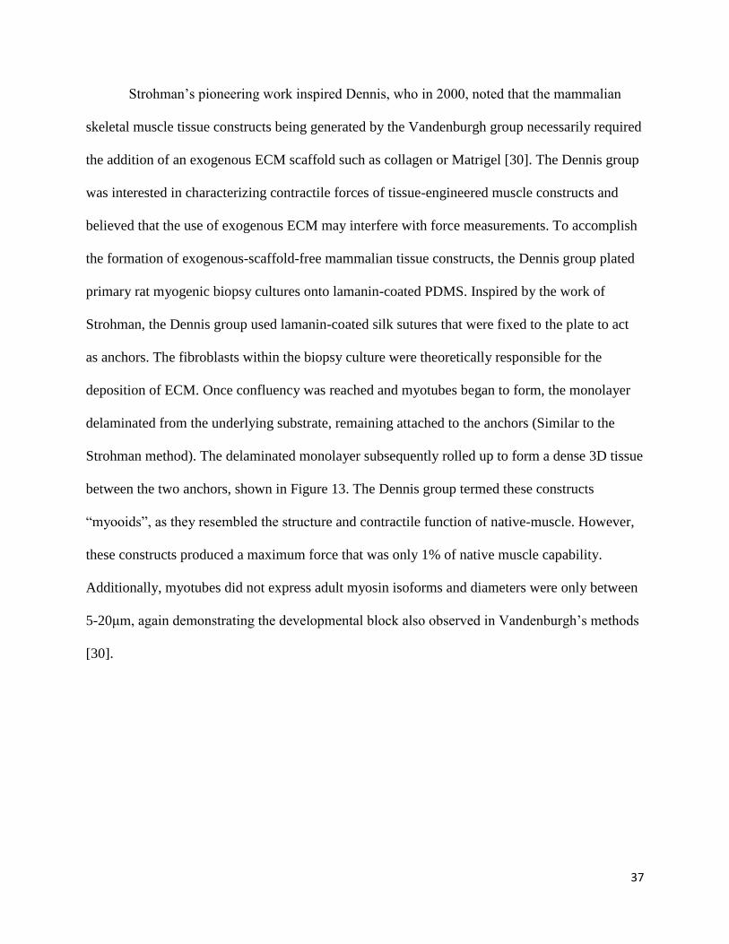
Strohman’s pioneering work inspired Dennis, who in 2000, noted that the mammalian
skeletal muscle tissue constructs being generated by the Vandenburgh group necessarily required
the addition of an exogenous ECM scaffold such as collagen or Matrigel [30]. The Dennis group
was interested in characterizing contractile forces of tissue-engineered muscle constructs and
believed that the use of exogenous ECM may interfere with force measurements. To accomplish
the formation of exogenous-scaffold-free mammalian tissue constructs, the Dennis group plated
primary rat myogenic biopsy cultures onto lamanin-coated PDMS. Inspired by the work of
Strohman, the Dennis group used lamanin-coated silk sutures that were fixed to the plate to act
as anchors. The fibroblasts within the biopsy culture were theoretically responsible for the
deposition of ECM. Once confluency was reached and myotubes began to form, the monolayer
delaminated from the underlying substrate, remaining attached to the anchors (Similar to the
Strohman method). The delaminated monolayer subsequently rolled up to form a dense 3D tissue
between the two anchors, shown in Figure 13. The Dennis group termed these constructs
“myooids”, as they resembled the structure and contractile function of native-muscle. However,
these constructs produced a maximum force that was only 1% of native muscle capability.
Additionally, myotubes did not express adult myosin isoforms and diameters were only between
5-20μm, again demonstrating the developmental block also observed in Vandenburgh’s methods
[30].
38
Figure 13: A: Representative image of a delaminating monolayer. B: Representative image of a rolled-up delaminated monolayer, remaining anchored to lamanin-coated suture anchors. C: Cross-section of a construct, showing similar structure to
native muscle [30].
In a 2005 article, Huang and Dennis noted the primary weaknesses of his monolayer
delamination tissue-engineering method [While these dense “myooids” were formed entirely of
cell and cell produced products, they took up to a month to fully form due to the requirement of
fibroblast secreted ECM. In an attempt to combat the excessive time required to form
monolayer-delamination tissues, Dennis presented a system in which primary myoblasts were
seeded onto a thin fibrin gel, which would subsequently contract around lamanin-coated silk
suture anchors upon myotube formation. These tissues formed faster than Dennis’s previous
myooid constructs, however these fibrin-assisted self-assembled tissues showed poorer myotube
density, similar to Vandenburgh and Powell’s HBAMs that also used excess exogenous ECM.
Typical of all current approaches to formation of skeletal muscle tissue, the fibrin-assisted self-
assembled tissues were composed of small diameter immature myotubes (~10um) and were only
able to produce a small fraction of native contraction force [5].
Dennis had shown that his fibrin-assisted self-assembled tissues did not allow for
complete fibrin degradation and thus sufficient cell-cell contact was not achieved and the density
and maturity of the tissue suffered. By 2011 Dennis showed that these tissues could be improved
39
by the incorporation of fibroblasts within the tissue constructs. However, the role of the
fibroblasts remained unexplained [31]. Another group later conducted a study examining the role
of fibroblasts in these fibrin-assisted self-assembled tissues. By forming constructs with Dennis’
fibrin-assisted self-assembly method using primary mouse myoblasts and mouse embryonic
fibroblasts, it was shown that fibroblasts maintained myotube viability, played a large role in
fibrin scaffold degradation and remodeling, and assisted in the rolling of the delaminated cell-
fibrin sheet [31].
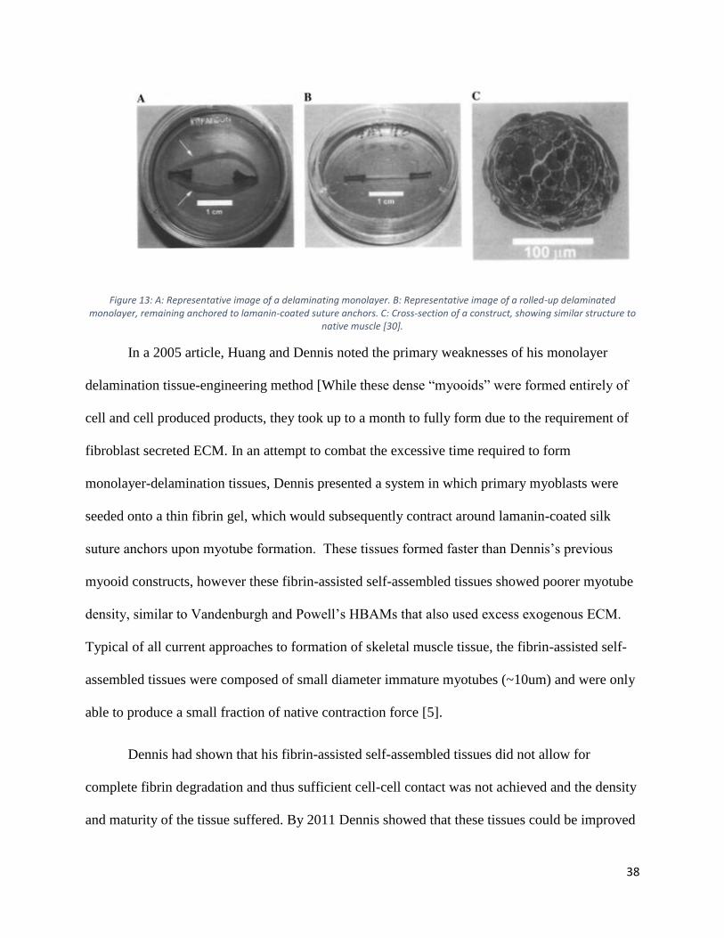
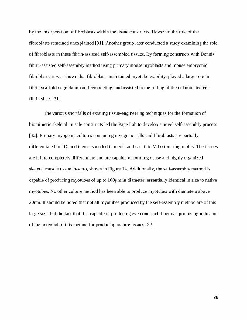
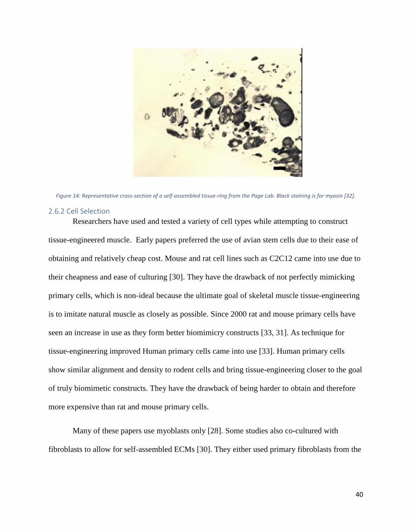
The various shortfalls of existing tissue-engineering techniques for the formation of
biomimetic skeletal muscle constructs led the Page Lab to develop a novel self-assembly process
[32]. Primary myogenic cultures containing myogenic cells and fibroblasts are partially
differentiated in 2D, and then suspended in media and cast into V-bottom ring molds. The tissues
are left to completely differentiate and are capable of forming dense and highly organized
skeletal muscle tissue in-vitro, shown in Figure 14. Additionally, the self-assembly method is
capable of producing myotubes of up to 100μm in diameter, essentially identical in size to native
myotubes. No other culture method has been able to produce myotubes with diameters above
20um. It should be noted that not all myotubes produced by the self-assembly method are of this
large size, but the fact that it is capable of producing even one such fiber is a promising indicator
of the potential of this method for producing mature tissues [32].
40
Figure 14: Representative cross-section of a self-assembled tissue-ring from the Page Lab. Black staining is for myosin [32].
2.6.2 Cell Selection
Researchers have used and tested a variety of cell types while attempting to construct
tissue-engineered muscle. Early papers preferred the use of avian stem cells due to their ease of
obtaining and relatively cheap cost. Mouse and rat cell lines such as C2C12 came into use due to
their cheapness and ease of culturing [30]. They have the drawback of not perfectly mimicking
primary cells, which is non-ideal because the ultimate goal of skeletal muscle tissue-engineering
is to imitate natural muscle as closely as possible. Since 2000 rat and mouse primary cells have
seen an increase in use as they form better biomimicry constructs [33, 31]. As technique for
tissue-engineering improved Human primary cells came into use [33]. Human primary cells
show similar alignment and density to rodent cells and bring tissue-engineering closer to the goal
of truly biomimetic constructs. They have the drawback of being harder to obtain and therefore
more expensive than rat and mouse primary cells.
Many of these papers use myoblasts only [28]. Some studies also co-cultured with
fibroblasts to allow for self-assembled ECMs [30]. They either used primary fibroblasts from the
41
same animal [31], fibroblast like cells such as 10T1/2 [30], or primary biopsy culture containing
both myogenic cells and fibroblasts [30].
2.6.3 Differentiation Techniques
Researchers have taken several different approaches to induce myogenic differentiation
in vitro. Over the years research groups have continuously altered differentiation protocols as
they refine their methods and use new cell types. Typically cells are seed and maintained in
growth media than switched to differentiation media. Some groups switch to maintenance media
after differentiation and some continue with differentiation media. Due to the high variance the
differentiation methods are summarized in Table 1 below.
42
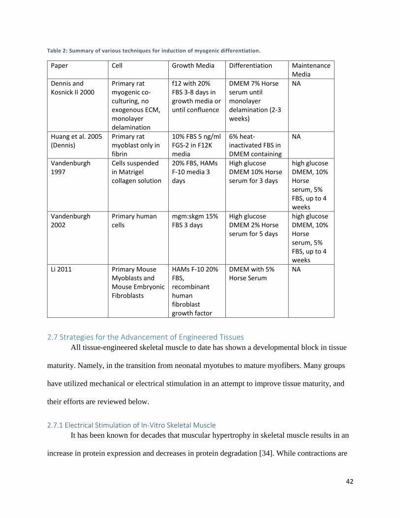
Table 2: Summary of various techniques for induction of myogenic differentiation.
Paper Cell Growth Media Differentiation Maintenance Media
Dennis and Kosnick II 2000
Primary rat myogenic co-culturing, no exogenous ECM, monolayer delamination
f12 with 20% FBS 3-8 days in growth media or until confluence
DMEM 7% Horse serum until monolayer delamination (2-3 weeks)
NA
Huang et al. 2005 (Dennis)
Primary rat myoblast only in fibrin
10% FBS 5 ng/ml FGS-2 in F12K media
6% heat-inactivated FBS in DMEM containing
NA
Vandenburgh 1997
Cells suspended in Matrigel collagen solution
20% FBS, HAMs F-10 media 3 days
High glucose DMEM 10% Horse serum for 3 days
high glucose DMEM, 10% Horse serum, 5% FBS, up to 4 weeks
Vandenburgh 2002
Primary human cells
mgm:skgm 15% FBS 3 days
High glucose DMEM 2% Horse serum for 5 days
high glucose DMEM, 10% Horse serum, 5% FBS, up to 4 weeks
Li 2011 Primary Mouse Myoblasts and Mouse Embryonic Fibroblasts
HAMs F-10 20% FBS, recombinant human fibroblast growth factor
DMEM with 5% Horse Serum
NA
2.7 Strategies for the Advancement of Engineered Tissues All tissue-engineered skeletal muscle to date has shown a developmental block in tissue
maturity. Namely, in the transition from neonatal myotubes to mature myofibers. Many groups
have utilized mechanical or electrical stimulation in an attempt to improve tissue maturity, and
their efforts are reviewed below.
2.7.1 Electrical Stimulation of In-Vitro Skeletal Muscle
It has been known for decades that muscular hypertrophy in skeletal muscle results in an
increase in protein expression and decreases in protein degradation [34]. While contractions are
43
triggered by motor-neurons in-vivo, in 1976, a group demonstrated that the effects of
hypertrophy could be mimicked in de-nervated skeletal in-vitro by stimulating differentiated
myotubes electrically. Further, the group showed that the increased protein expression is due
primarily to an increase in contractile protein synthesis, such as myosin heavy chain [34].
Proteins involved directly in contraction, such as myosin heavy chain, are not the only
proteins essential for the process. One of the key pieces to muscle contraction is the transport of
glucose into the cell to ultimately provide the ATP necessary for contraction. It has been shown
that electrical stimulation is capable of up-regulating glucose intake through both insulin and
GLUT4 dependent pathways [35]. Additionally, it has been show that embryonic-derived
skeletal muscle further matures when stimulated in-vitro [36]. While unstimulated myotubes
derived from avian embryos express an embryonic form of myosin heavy chain, stimulated
myotubes express a form of late-embryonic myosin heavy chain, indicating a role of electrical
stimulation in skeletal muscle maturation.
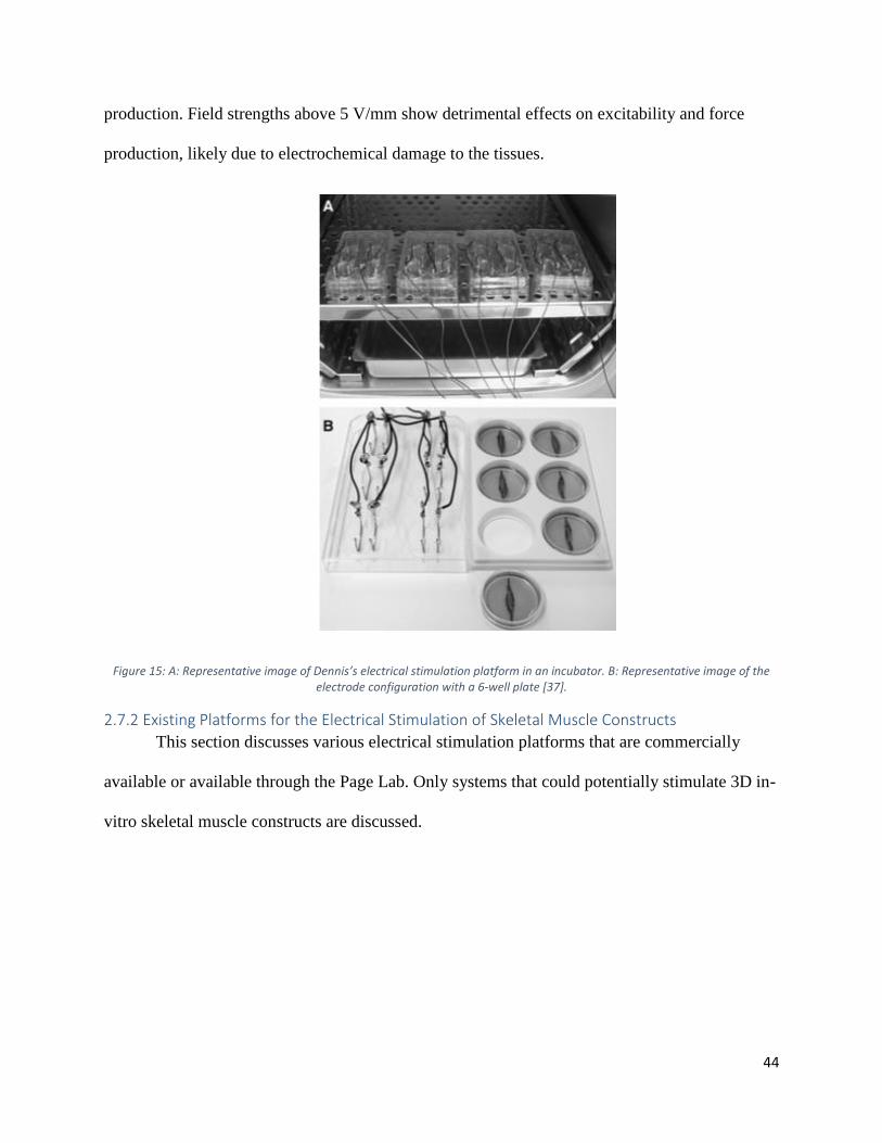
These observations led Dennis to evaluate the effects of electrical stimulation on his
fibrin-assisted self-assembly tissue models, shown in Figure 15 [37]. Consistent with prior
research, Dennis saw increased excitability and force production from electrically stimulated
tissues, indicating an advance in maturity. Dennis raises some key points about the stimulation of
3D muscle tissue. The purpose of electrical stimulation is to mimic the function of motor-
neurons, which trigger the propagation of an action potential across the myotube membrane,
ultimately triggering release of calcium from the sarcoplasmic reticulum, thus triggering
contraction. Dennis shows that electrical field strength effects force production and excitability
significantly. Field strengths of 2.5 V/mm show the highest increase in excitability and force
44
production. Field strengths above 5 V/mm show detrimental effects on excitability and force
production, likely due to electrochemical damage to the tissues.
Figure 15: A: Representative image of Dennis’s electrical stimulation platform in an incubator. B: Representative image of the electrode configuration with a 6-well plate [37].
2.7.2 Existing Platforms for the Electrical Stimulation of Skeletal Muscle Constructs
This section discusses various electrical stimulation platforms that are commercially
available or available through the Page Lab. Only systems that could potentially stimulate 3D in-
vitro skeletal muscle constructs are discussed.
45
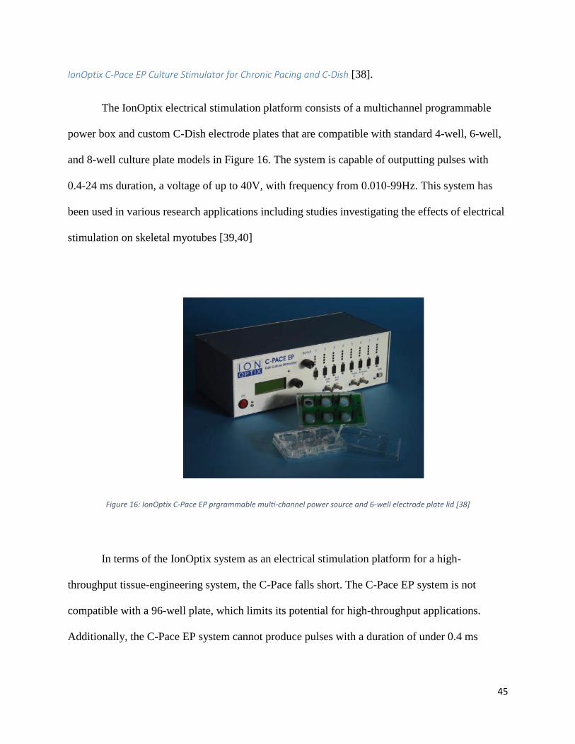
IonOptix C-Pace EP Culture Stimulator for Chronic Pacing and C-Dish [38].
The IonOptix electrical stimulation platform consists of a multichannel programmable
power box and custom C-Dish electrode plates that are compatible with standard 4-well, 6-well,
and 8-well culture plate models in Figure 16. The system is capable of outputting pulses with
0.4-24 ms duration, a voltage of up to 40V, with frequency from 0.010-99Hz. This system has
been used in various research applications including studies investigating the effects of electrical
stimulation on skeletal myotubes [39,40]
Figure 16: IonOptix C-Pace EP prgrammable multi-channel power source and 6-well electrode plate lid [38]
In terms of the IonOptix system as an electrical stimulation platform for a high-
throughput tissue-engineering system, the C-Pace falls short. The C-Pace EP system is not
compatible with a 96-well plate, which limits its potential for high-throughput applications.
Additionally, the C-Pace EP system cannot produce pulses with a duration of under 0.4 ms
46
Myomics MyoForce Analysis System (MFASTM) [41]
Vandenburgh’s company Myomics used the MyoForce Analysis System (MFASTM)
electrical stimulation platform. The platform was not designed to stimulate constructs for the
purpose of maturation; rather it was designed to trigger tetanic contractions for the purpose of
contractile assessment of mBAMs. The system could theoretically be used to provide electrical
stimulation regimens for the purpose of tissue maturity enhancement, however the system is only
capable of stimulating one tissue construct at a time. This, accompanied by the fact that the
system functions outside of an incubator, means the MFASTM is unsuitable for the high-
throughput stimulation of tissue-engineered skeletal muscle constructs.
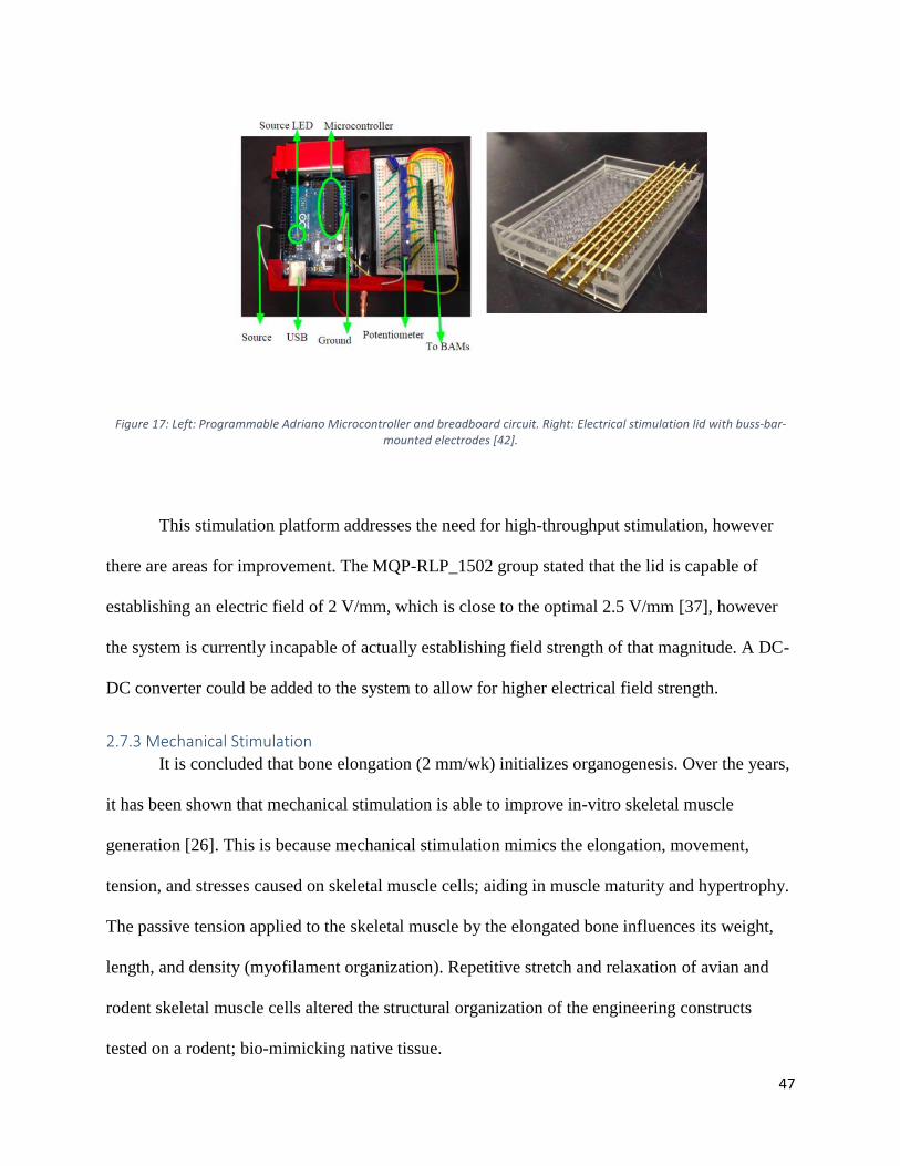
MQP-RLP-1502 Electrical Stimulation Lid
A 2015 WPI MQP team, MQP-RLP-1502, was commissioned to address the lack of an
existing platform for the high-throughput stimulation of tissue-engineered skeletal muscle
constructs. The group created a 96-electrode stimulation lid (Figure 17). The lid is controlled by
an Arduino Uno microcontroller, which allows for the programming of an automated
customizable stimulation regimen. The device is EtO sterilizable, corrosion resistant, functional
in an incubator, and is able to establish maximum of 4.8V across stainless steel electrodes. The
device is designed for use in a in a 96-well plate, with stainless steel electrodes in each well
attached to brass buss-bars. The lid is capable of establishing a maximum electric field of ~1.6
V/mm, however the field strength is adjustable using potentiometers [42].
47
Figure 17: Left: Programmable Adriano Microcontroller and breadboard circuit. Right: Electrical stimulation lid with buss-bar-mounted electrodes [42].
This stimulation platform addresses the need for high-throughput stimulation, however
there are areas for improvement. The MQP-RLP_1502 group stated that the lid is capable of
establishing an electric field of 2 V/mm, which is close to the optimal 2.5 V/mm [37], however
the system is currently incapable of actually establishing field strength of that magnitude. A DC-
DC converter could be added to the system to allow for higher electrical field strength.
2.7.3 Mechanical Stimulation
It is concluded that bone elongation (2 mm/wk) initializes organogenesis. Over the years,
it has been shown that mechanical stimulation is able to improve in-vitro skeletal muscle
generation [26]. This is because mechanical stimulation mimics the elongation, movement,
tension, and stresses caused on skeletal muscle cells; aiding in muscle maturity and hypertrophy.
The passive tension applied to the skeletal muscle by the elongated bone influences its weight,
length, and density (myofilament organization). Repetitive stretch and relaxation of avian and
rodent skeletal muscle cells altered the structural organization of the engineering constructs
tested on a rodent; bio-mimicking native tissue.
48
2.7.4 Existing Platforms for the Mechanical Stimulation of Skeletal Muscle Constructs
This section discusses various mechanical stimulation platforms that are commercially
available or available through the Page Lab. Only systems that could potentially stimulate 3D in-
vitro skeletal muscle constructs are discussed.
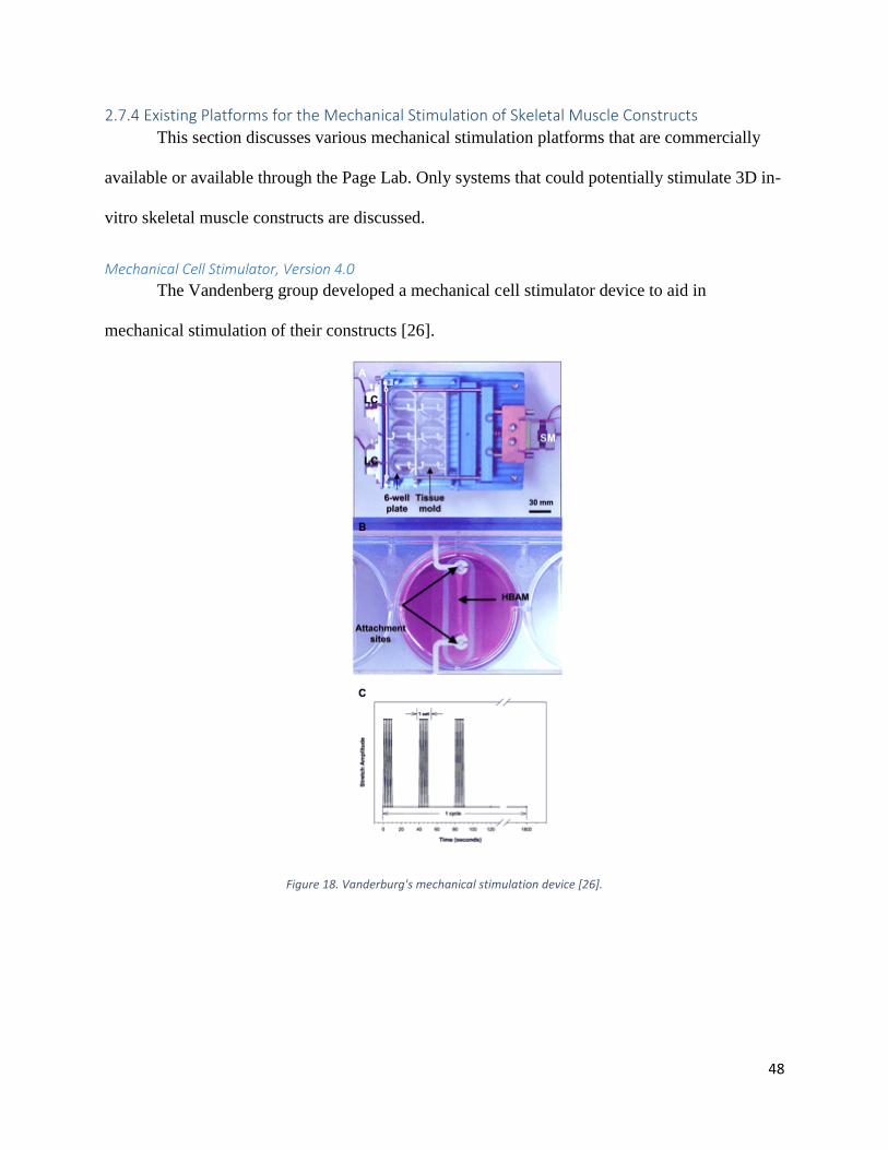
Mechanical Cell Stimulator, Version 4.0
The Vandenberg group developed a mechanical cell stimulator device to aid in
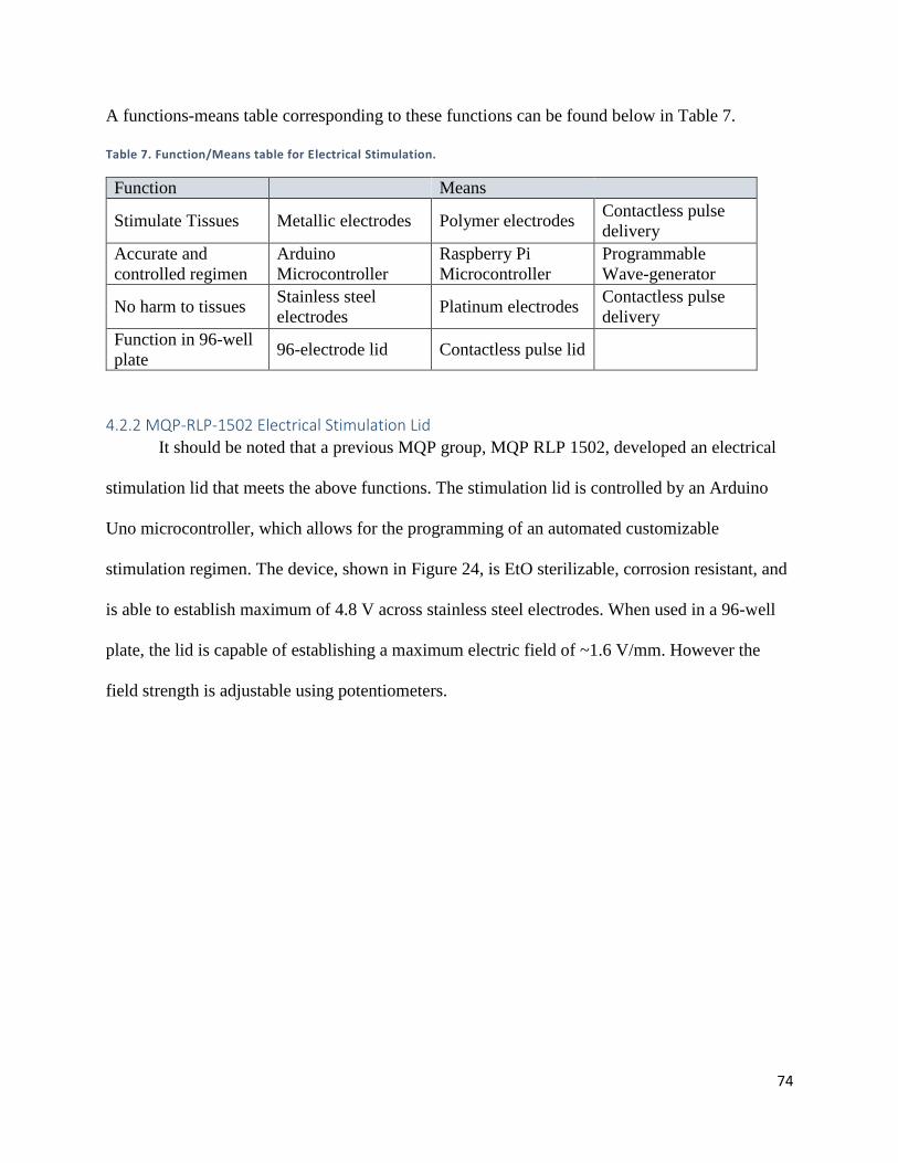
It should be noted that a previous MQP group, MQP RLP 1502, developed an electrical
stimulation lid that meets the above functions. The stimulation lid is controlled by an Arduino
Uno microcontroller, which allows for the programming of an automated customizable
stimulation regimen. The device, shown in Figure 24, is EtO sterilizable, corrosion resistant, and
is able to establish maximum of 4.8 V across stainless steel electrodes. When used in a 96-well
plate, the lid is capable of establishing a maximum electric field of ~1.6 V/mm. However the
field strength is adjustable using potentiometers.
75
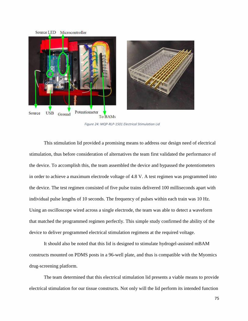
This stimulation lid provided a promising means to address our design need of electrical
stimulation, thus before consideration of alternatives the team first validated the performance of
the device. To accomplish this, the team assembled the device and bypassed the potentiometers
in order to achieve a maximum electrode voltage of 4.8 V. A test regimen was programmed into
the device. The test regimen consisted of five pulse trains delivered 100 milliseconds apart with
individual pulse lengths of 10 seconds. The frequency of pulses within each train was 10 Hz.
Using an oscilloscope wired across a single electrode, the team was able to detect a waveform
that matched the programmed regimen perfectly. This simple study confirmed the ability of the
device to deliver programmed electrical stimulation regimens at the required voltage.
It should also be noted that this lid is designed to stimulate hydrogel-assisted mBAM
constructs mounted on PDMS posts in a 96-well plate, and thus is compatible with the Myomics
drug-screening platform.
The team determined that this electrical stimulation lid presents a viable means to provide
electrical stimulation for our tissue constructs. Not only will the lid perform its intended function
Figure 24: MQP-RLP-1501 Electrical Stimulation Lid
76
within our tissue-engineering system, but also the use of this pre-fabricated lid will save the team
valuable time and resources that would otherwise be dedicated to the development of a new
electrical stimulation system. For these reasons, the MQP-RPL-1502 electrical stimulation lid, or
a variation of it, was chosen as a final system design component.
4.3 Mechanical Stimulation As discussed in the literature review, skeletal muscle is subjected to mechanical forces
during development. As such, mechanical stimulation has been used as a strategy to enhance
tissue-engineered skeletal muscle maturity. Mechanical stimulation has been shown to increase
muscle maturation, aiding in the betterment of myofiber alignment and increasing myofiber
diameters and contractile protein production [26]. These factors improve overall tissue
biomimicry of the cultured tissue, including contractile force.
4.3.1 Mechanical Stimulation Means
The team’s mechanical stimulation device must meet the functions and sub-functions
described in Chapter 3, which are restated below:
1. Stimulates tissue constructs, mimicking native mechanical stretching and relaxation
2. Displace anchorage points
3. Capable of accurate, controlled and automated stimulation regimens on a dual-post
anchorage system
4. Cause no harm to either the culturing method nor the tissue constructs
5. Function in a 96-well plate for high-throughput production
A functions-means table corresponding to these functions can be seen below in Table 8.
77
Table 8: Functions/Mean for Mechanical Stimulation.
Function Means
Stimulate tissue
constructs (force
production and transfer)
Hydraulic system Pneumatic
system
Stepper-motor
assembly
Brake cable
assembly
Sliding
Magnetic
rack
Displace anchorage
points Sliding ‘comb’ rack
Magnetic
Posts
‘Balloon’ post
platform
Accurate and automated
stimulation regimens
Arduino
microcontroller
Programmable
syringe sump
Programmable
air compressor
Raspberry Pi
Microcontroller
Cause no harm to tissues No contact with
cells or media
Biocompatible
materials
Function in 96-well plate Sliding ‘comb- rack
with 96 combs
Magnetic
Posts
96-balloon
modification of
96-well plate
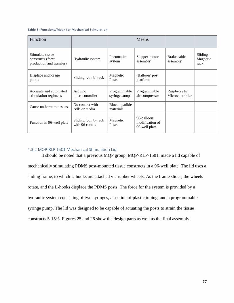
4.3.2 MQP-RLP 1501 Mechanical Stimulation Lid
It should be noted that a previous MQP group, MQP-RLP-1501, made a lid capable of
mechanically stimulating PDMS post-mounted tissue constructs in a 96-well plate. The lid uses a
sliding frame, to which L-hooks are attached via rubber wheels. As the frame slides, the wheels
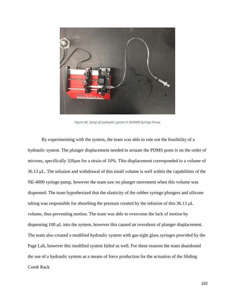
rotate, and the L-hooks displace the PDMS posts. The force for the system is provided by a
hydraulic system consisting of two syringes, a section of plastic tubing, and a programmable
syringe pump. The lid was designed to be capable of actuating the posts to strain the tissue
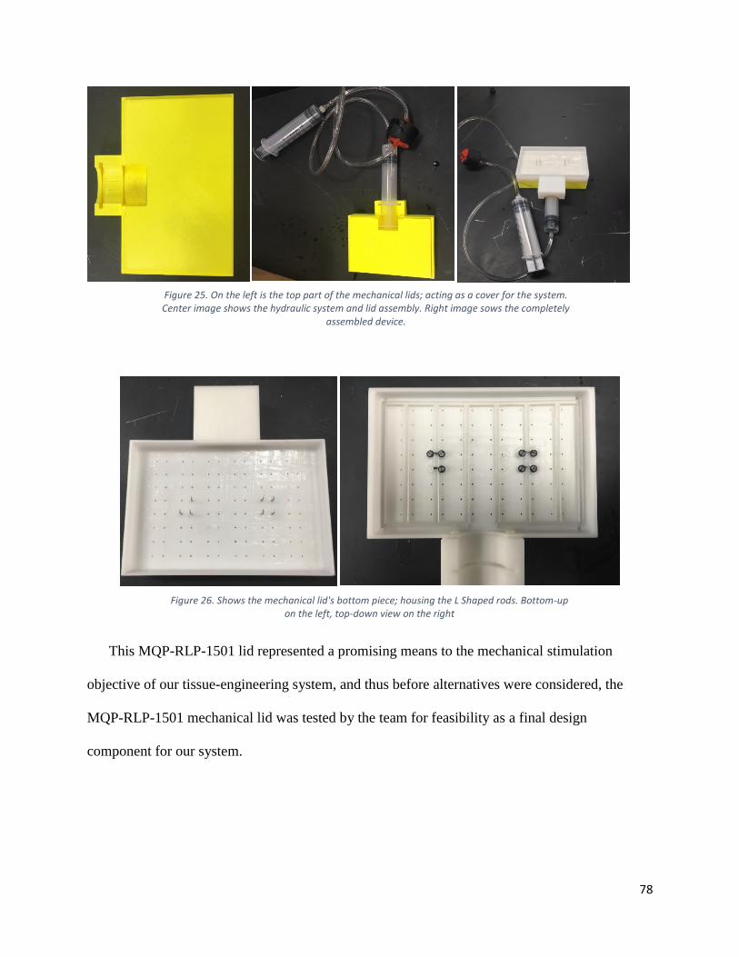
constructs 5-15%. Figures 25 and 26 show the design parts as well as the final assembly.
78
This MQP-RLP-1501 lid represented a promising means to the mechanical stimulation
objective of our tissue-engineering system, and thus before alternatives were considered, the
MQP-RLP-1501 mechanical lid was tested by the team for feasibility as a final design
component for our system.
Figure 25. On the left is the top part of the mechanical lids; acting as a cover for the system. Center image shows the hydraulic system and lid assembly. Right image sows the completely
assembled device.
Figure 26. Shows the mechanical lid's bottom piece; housing the L Shaped rods. Bottom-up on the left, top-down view on the right
79
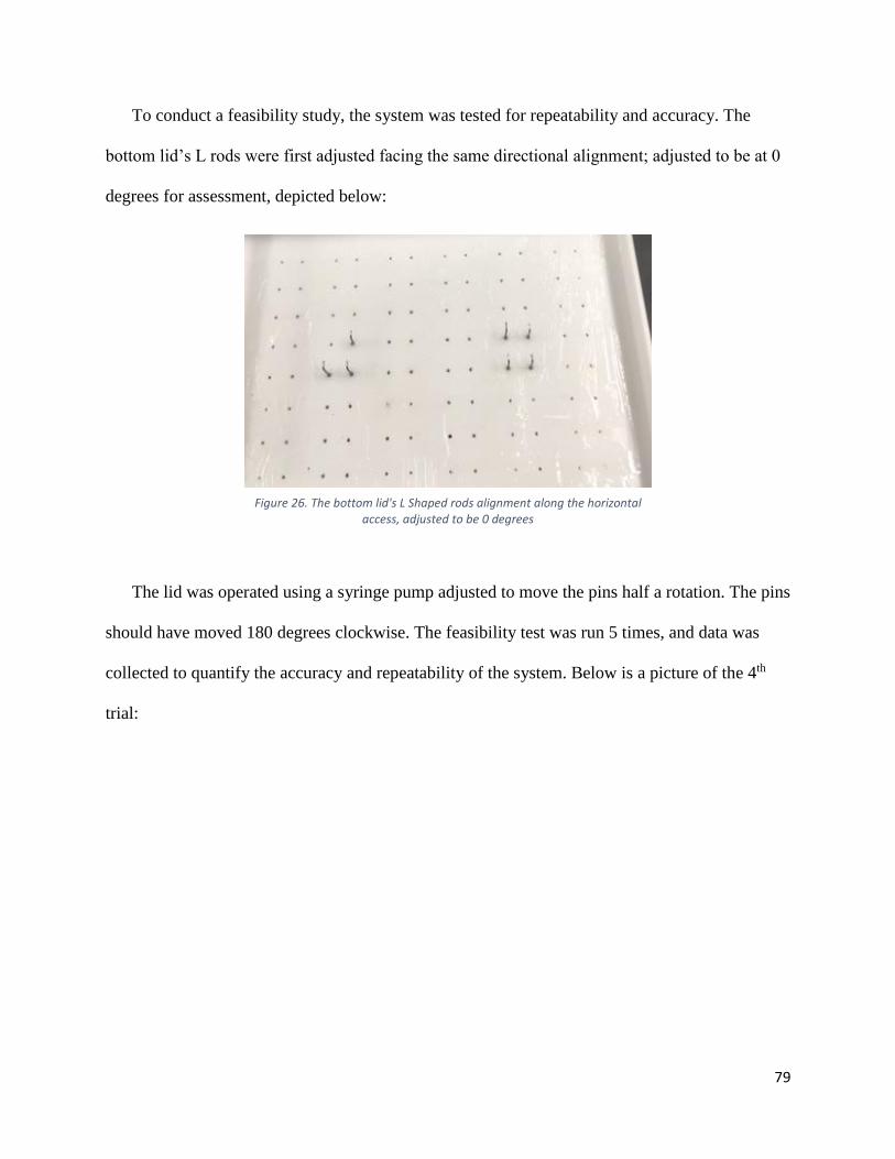
To conduct a feasibility study, the system was tested for repeatability and accuracy. The
bottom lid’s L rods were first adjusted facing the same directional alignment; adjusted to be at 0
degrees for assessment, depicted below:
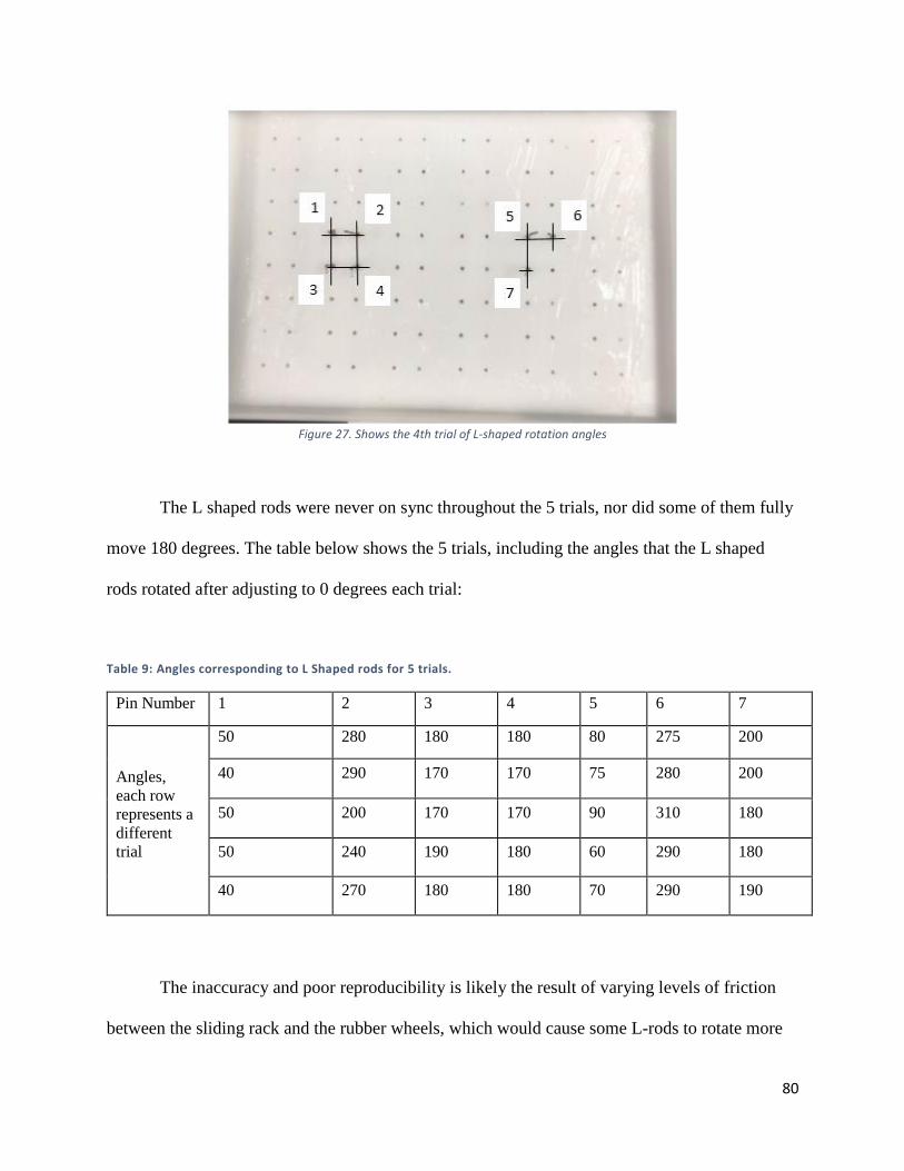
The lid was operated using a syringe pump adjusted to move the pins half a rotation. The pins
should have moved 180 degrees clockwise. The feasibility test was run 5 times, and data was
collected to quantify the accuracy and repeatability of the system. Below is a picture of the 4th
trial:
Figure 26. The bottom lid's L Shaped rods alignment along the horizontal access, adjusted to be 0 degrees
80
Figure 27. Shows the 4th trial of L-shaped rotation angles
The L shaped rods were never on sync throughout the 5 trials, nor did some of them fully
move 180 degrees. The table below shows the 5 trials, including the angles that the L shaped
rods rotated after adjusting to 0 degrees each trial:
Table 9: Angles corresponding to L Shaped rods for 5 trials.
Pin Number 1 2 3 4 5 6 7
Angles,
each row
represents a
different
trial
50 280 180 180 80 275 200
40 290 170 170 75 280 200
50 200 170 170 90 310 180
50 240 190 180 60 290 180
40 270 180 180 70 290 190
The inaccuracy and poor reproducibility is likely the result of varying levels of friction
between the sliding rack and the rubber wheels, which would cause some L-rods to rotate more
81
or less than others. Another potential source of the poor accuracy and reproducibility could be
poor precision within the hydraulic system itself. The syringes used were large, and thus had
large rubber stoppers, which likely compress and decompress during the operation of the system.
The results of this feasibility study suggest that the MQP-RLP-1501 mechanical stimulation lid
may not represent a viable means to the mechanical stimulation functional block, and thus this
lid was abandoned as a final design component.
4.3.3 Mechanical Stimulation Conceptual Designs
Using the functions-means table described in the previous section, the team generated three
conceptual designs to meet the mechanical stimulation function black requirements:
1. Magnetic Posts with Magnetic Sliding Rack
2. ‘Balloon’ Assembly
3. Sliding ‘Comb’ Rack
82
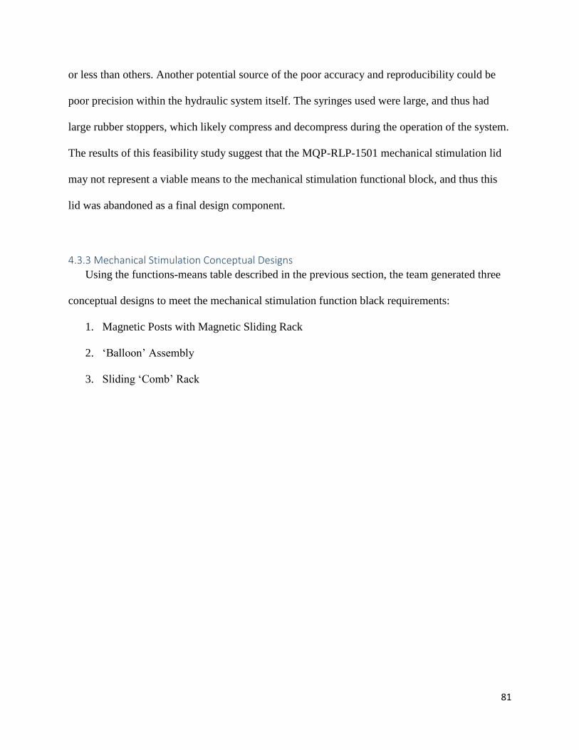
Conceptual Design 1: Magnetic Posts with Magnetic Sliding Rack
The first conceptual design that the team generated relied on magnetic force production
to actuate the tissue anchorage points. Magnetic iron particulate would be embedded within the
PDMS posts themselves, and a magnetic lid would slide over the 96-well plate, theoretically
displacing the posts to which the tissue would be mounted. The sliding magnetic rack could be
displaced with a hydraulic system of a brake-cable assembly, which would allow function in an
incubator. A preliminary model of the system is depicted in Figure 28 below.
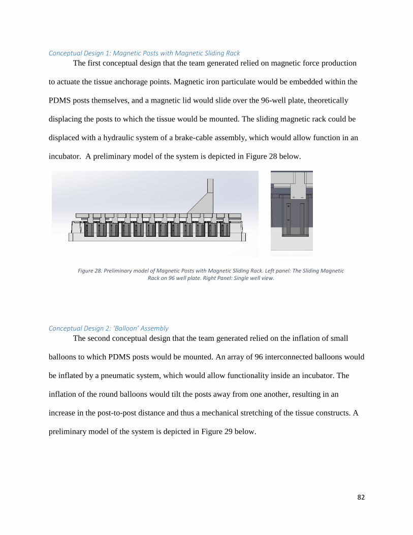
Conceptual Design 2: ‘Balloon’ Assembly
The second conceptual design that the team generated relied on the inflation of small
balloons to which PDMS posts would be mounted. An array of 96 interconnected balloons would
be inflated by a pneumatic system, which would allow functionality inside an incubator. The
inflation of the round balloons would tilt the posts away from one another, resulting in an
increase in the post-to-post distance and thus a mechanical stretching of the tissue constructs. A
preliminary model of the system is depicted in Figure 29 below.
Figure 28. Preliminary model of Magnetic Posts with Magnetic Sliding Rack. Left panel: The Sliding Magnetic Rack on 96 well plate. Right Panel: Single well view.
83
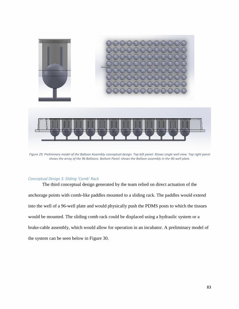
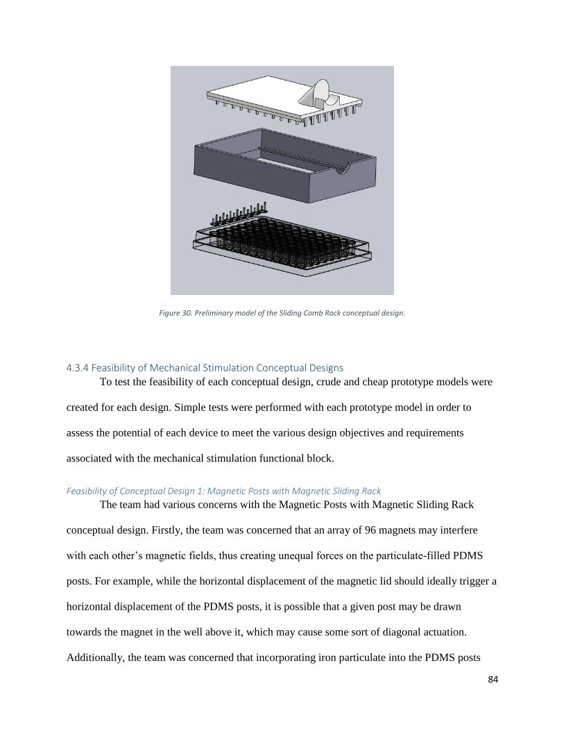
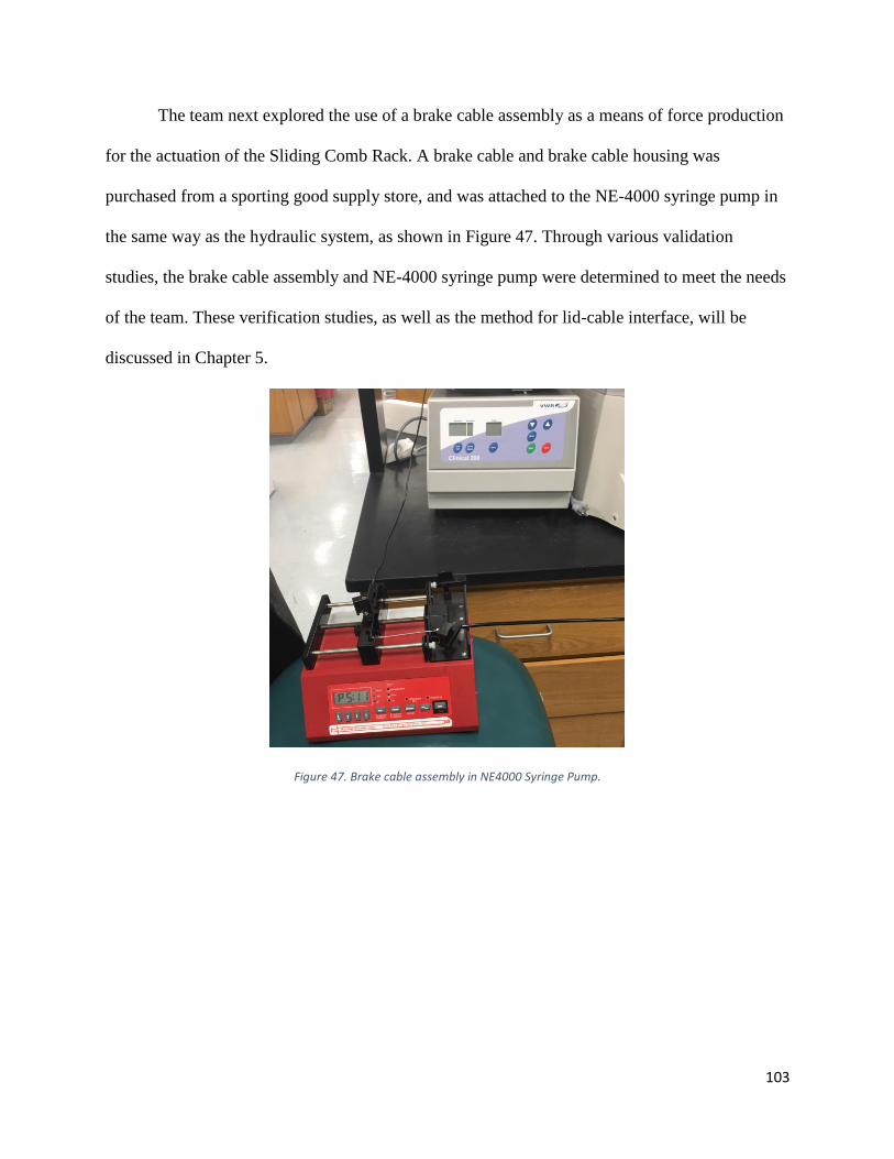
Conceptual Design 3: Sliding ‘Comb’ Rack
The third conceptual design generated by the team relied on direct actuation of the
anchorage points with comb-like paddles mounted to a sliding rack. The paddles would extend
into the well of a 96-well plate and would physically push the PDMS posts to which the tissues
would be mounted. The sliding comb rack could be displaced using a hydraulic system or a
brake-cable assembly, which would allow for operation in an incubator. A preliminary model of
the system can be seen below in Figure 30.
Figure 29. Preliminary model of the Balloon Assembly conceptual design. Top left panel: Shows single well view. Top right panel shows the array of the 96 Balloons. Bottom Panel: shows the Balloon assembly in the 96-well plate.
84
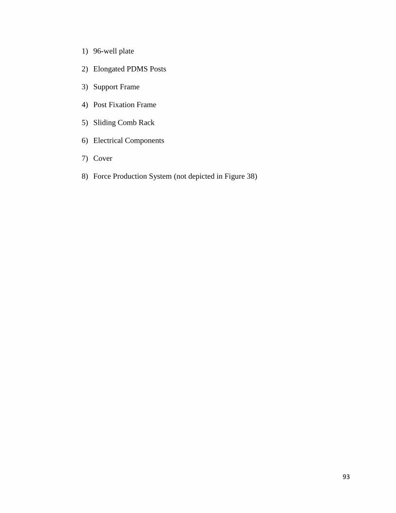
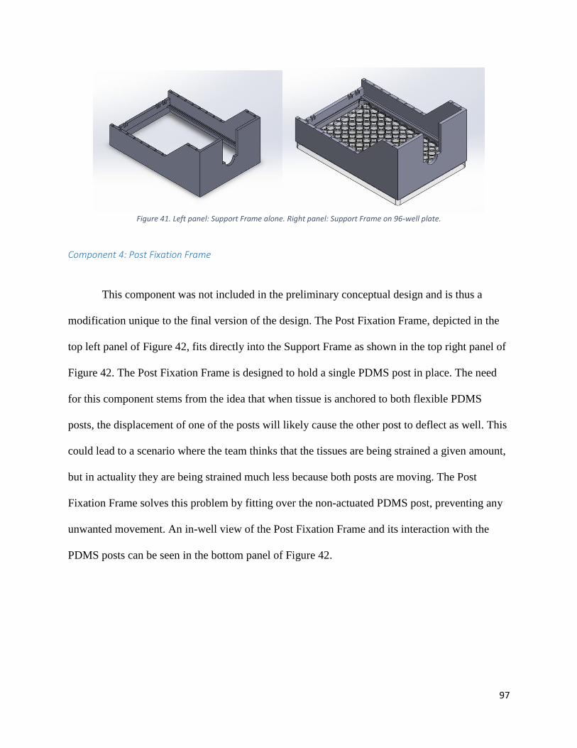
Figure 30. Preliminary model of the Sliding Comb Rack conceptual design.
4.3.4 Feasibility of Mechanical Stimulation Conceptual Designs
To test the feasibility of each conceptual design, crude and cheap prototype models were
created for each design. Simple tests were performed with each prototype model in order to
assess the potential of each device to meet the various design objectives and requirements
associated with the mechanical stimulation functional block.
Feasibility of Conceptual Design 1: Magnetic Posts with Magnetic Sliding Rack
The team had various concerns with the Magnetic Posts with Magnetic Sliding Rack
conceptual design. Firstly, the team was concerned that an array of 96 magnets may interfere
with each other’s magnetic fields, thus creating unequal forces on the particulate-filled PDMS
posts. For example, while the horizontal displacement of the magnetic lid should ideally trigger a
horizontal displacement of the PDMS posts, it is possible that a given post may be drawn
towards the magnet in the well above it, which may cause some sort of diagonal actuation.
Additionally, the team was concerned that incorporating iron particulate into the PDMS posts
85
may allow for the leaching of cytotoxic iron ions into the culture media, which could adversely
affect tissue health.
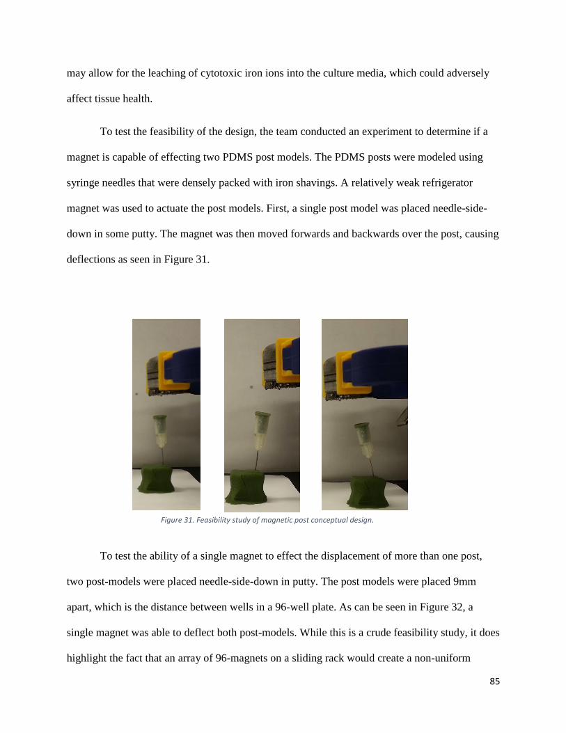
To test the feasibility of the design, the team conducted an experiment to determine if a
magnet is capable of effecting two PDMS post models. The PDMS posts were modeled using
syringe needles that were densely packed with iron shavings. A relatively weak refrigerator
magnet was used to actuate the post models. First, a single post model was placed needle-side-
down in some putty. The magnet was then moved forwards and backwards over the post, causing
deflections as seen in Figure 31.
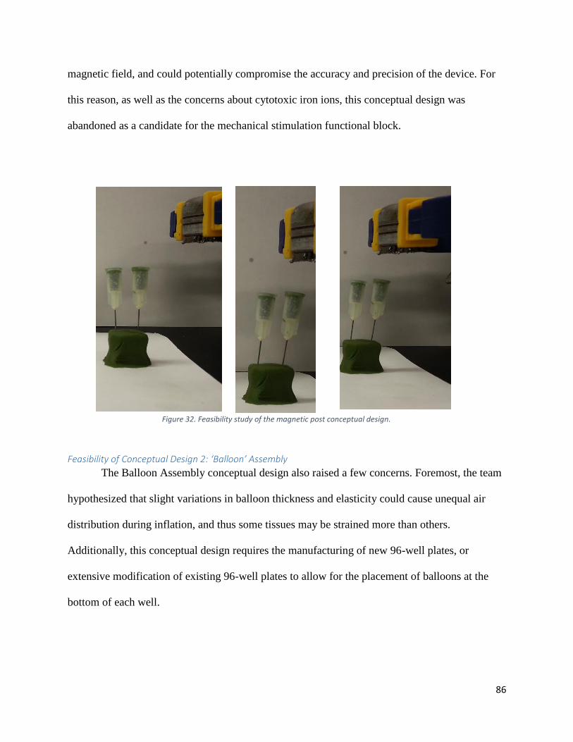
To test the ability of a single magnet to effect the displacement of more than one post,
two post-models were placed needle-side-down in putty. The post models were placed 9mm
apart, which is the distance between wells in a 96-well plate. As can be seen in Figure 32, a
single magnet was able to deflect both post-models. While this is a crude feasibility study, it does
highlight the fact that an array of 96-magnets on a sliding rack would create a non-uniform
Figure 31. Feasibility study of magnetic post conceptual design.
86
magnetic field, and could potentially compromise the accuracy and precision of the device. For
this reason, as well as the concerns about cytotoxic iron ions, this conceptual design was
abandoned as a candidate for the mechanical stimulation functional block.
Feasibility of Conceptual Design 2: ‘Balloon’ Assembly
The Balloon Assembly conceptual design also raised a few concerns. Foremost, the team
hypothesized that slight variations in balloon thickness and elasticity could cause unequal air
distribution during inflation, and thus some tissues may be strained more than others.
Additionally, this conceptual design requires the manufacturing of new 96-well plates, or
extensive modification of existing 96-well plates to allow for the placement of balloons at the
bottom of each well.
Figure 32. Feasibility study of the magnetic post conceptual design.
87
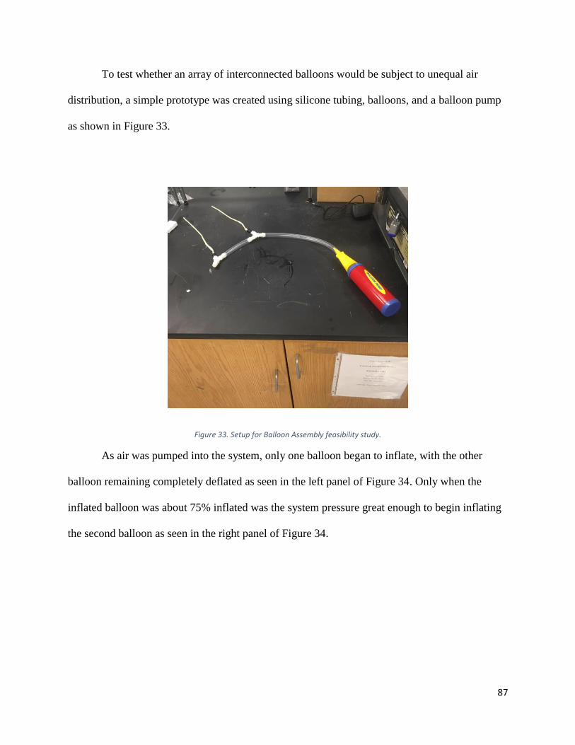
To test whether an array of interconnected balloons would be subject to unequal air
distribution, a simple prototype was created using silicone tubing, balloons, and a balloon pump
as shown in Figure 33.
Figure 33. Setup for Balloon Assembly feasibility study.
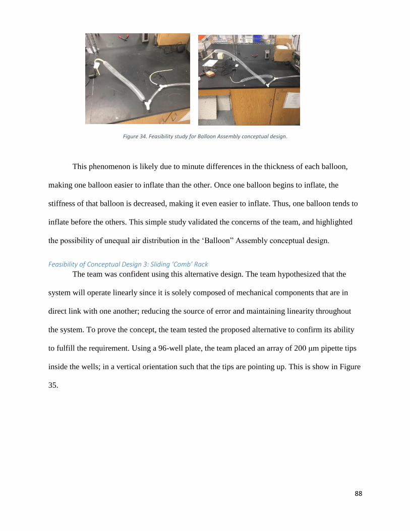
As air was pumped into the system, only one balloon began to inflate, with the other
balloon remaining completely deflated as seen in the left panel of Figure 34. Only when the
inflated balloon was about 75% inflated was the system pressure great enough to begin inflating
the second balloon as seen in the right panel of Figure 34.
88
Figure 34. Feasibility study for Balloon Assembly conceptual design.
This phenomenon is likely due to minute differences in the thickness of each balloon,
making one balloon easier to inflate than the other. Once one balloon begins to inflate, the
stiffness of that balloon is decreased, making it even easier to inflate. Thus, one balloon tends to
inflate before the others. This simple study validated the concerns of the team, and highlighted
the possibility of unequal air distribution in the ‘Balloon” Assembly conceptual design.
Feasibility of Conceptual Design 3: Sliding ‘Comb’ Rack
The team was confident using this alternative design. The team hypothesized that the
system will operate linearly since it is solely composed of mechanical components that are in
direct link with one another; reducing the source of error and maintaining linearity throughout
the system. To prove the concept, the team tested the proposed alternative to confirm its ability
to fulfill the requirement. Using a 96-well plate, the team placed an array of 200 μm pipette tips
inside the wells; in a vertical orientation such that the tips are pointing up. This is show in Figure
35.
89
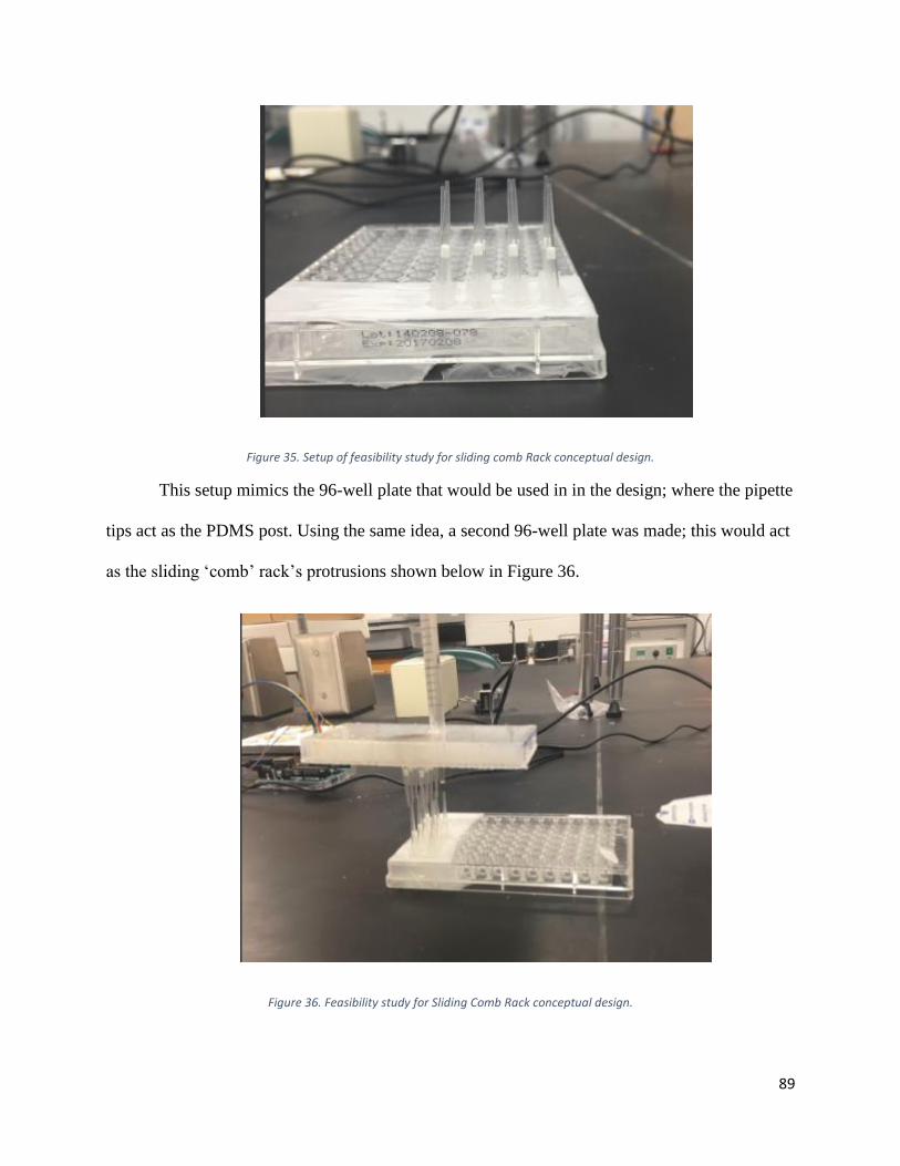
Figure 35. Setup of feasibility study for sliding comb Rack conceptual design.
This setup mimics the 96-well plate that would be used in in the design; where the pipette
tips act as the PDMS post. Using the same idea, a second 96-well plate was made; this would act
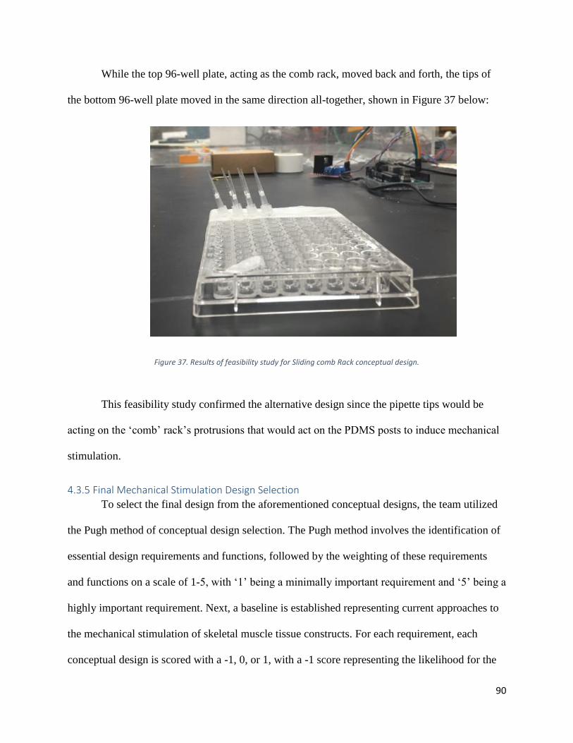
as the sliding ‘comb’ rack’s protrusions shown below in Figure 36.
Figure 36. Feasibility study for Sliding Comb Rack conceptual design.
90
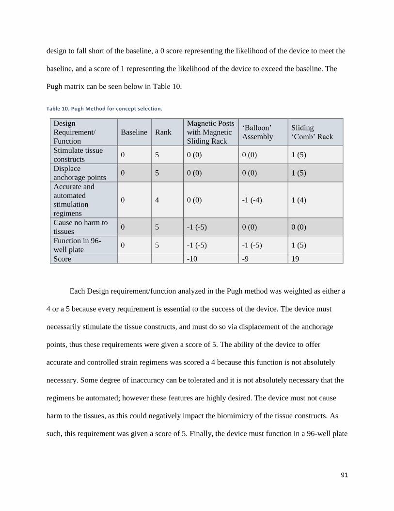
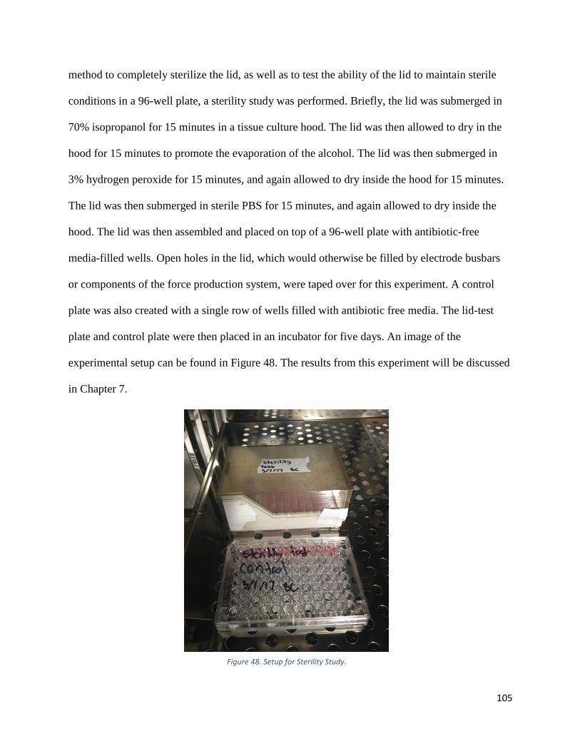
While the top 96-well plate, acting as the comb rack, moved back and forth, the tips of
the bottom 96-well plate moved in the same direction all-together, shown in Figure 37 below:
Figure 37. Results of feasibility study for Sliding comb Rack conceptual design.
This feasibility study confirmed the alternative design since the pipette tips would be
acting on the ‘comb’ rack’s protrusions that would act on the PDMS posts to induce mechanical
stimulation.
4.3.5 Final Mechanical Stimulation Design Selection
To select the final design from the aforementioned conceptual designs, the team utilized
the Pugh method of conceptual design selection. The Pugh method involves the identification of
essential design requirements and functions, followed by the weighting of these requirements
and functions on a scale of 1-5, with ‘1’ being a minimally important requirement and ‘5’ being a
highly important requirement. Next, a baseline is established representing current approaches to
the mechanical stimulation of skeletal muscle tissue constructs. For each requirement, each
conceptual design is scored with a -1, 0, or 1, with a -1 score representing the likelihood for the
91
design to fall short of the baseline, a 0 score representing the likelihood of the device to meet the
baseline, and a score of 1 representing the likelihood of the device to exceed the baseline. The
Pugh matrix can be seen below in Table 10.
Table 10. Pugh Method for concept selection.
Design
Requirement/
Function
Baseline Rank
Magnetic Posts
with Magnetic
Sliding Rack
‘Balloon’
Assembly
Sliding
‘Comb’ Rack
Stimulate tissue
constructs 0 5 0 (0) 0 (0) 1 (5)
Displace
anchorage points 0 5 0 (0) 0 (0) 1 (5)
Accurate and
automated
stimulation
regimens
0 4 0 (0) -1 (-4) 1 (4)
Cause no harm to
tissues 0 5 -1 (-5) 0 (0) 0 (0)
Function in 96-
well plate 0 5 -1 (-5) -1 (-5) 1 (5)
Score -10 -9 19
Each Design requirement/function analyzed in the Pugh method was weighted as either a
4 or a 5 because every requirement is essential to the success of the device. The device must
necessarily stimulate the tissue constructs, and must do so via displacement of the anchorage
points, thus these requirements were given a score of 5. The ability of the device to offer
accurate and controlled strain regimens was scored a 4 because this function is not absolutely
necessary. Some degree of inaccuracy can be tolerated and it is not absolutely necessary that the
regimens be automated; however these features are highly desired. The device must not cause
harm to the tissues, as this could negatively impact the biomimicry of the tissue constructs. As
such, this requirement was given a score of 5. Finally, the device must function in a 96-well plate
92
in order to be compatible with the high-throughput Myomics drug-screening platform, and thus
this requirement was scored as a 5 as well.
As the conceptual designs were scored using the Pugh method, the results of the
feasibility studies were taken into consideration. The Magnetic Post conceptual design would not
likely outperform the baseline, as the non-uniform magnetic field may cause variations in PDMS
displacement and the iron particulates may cause tissue damage. The ‘Balloon’ Assembly
conceptual design was also predicted to underperform the baseline, as uneven air distribution
may cause unequal post deflection and would require the manufacture of modified 96-well
plates. The Sliding ‘Comb’ Rack conceptual design was predicted to vastly outperform the
baseline. This concept is much simpler than the others, and relies merely on a plastic ‘paddle’ to
push on a flexible PDMS to displace it. Additionally, this system relies on only one moving part,
thus increasing the likelihood that this design will provide accurate and controlled strain
regimens. The sliding rack is compatible with both hydraulic systems and brake-cable
assemblies, both of which can be made using a programmable syringe pump to provide precise
and automated strain regimens. This combined with the prediction that the device could be
fabricated out of biocompatible materials to avoid cytotoxicity, lead to selection of this
conceptual design for further development into the final design.
4.3.6 Modification and Finalization of Final Design
The initial model of the ‘Comb’ Rack concept is shown below in the left panel of Figure
38, and the right panel shows the finalized device. The following sections describe how the team
arrived at the final design. The functionality of each feature of the final design will also be
discussed in these sections. The sections will be organized by design component, which will be
discusses in the following order:
93
1) 96-well plate
2) Elongated PDMS Posts
3) Support Frame
4) Post Fixation Frame
5) Sliding Comb Rack
6) Electrical Components
7) Cover
8) Force Production System (not depicted in Figure 38)
94
Figure 38. Left panel: Preliminary model for sliding comb Rack conceptual design. Right panel: Final design for Sliding Comb Rack
Component 1: 96-well Plate
Figure 39 shows a CAD model of a standard 96-well plate. While this plate is not
something that was designed or modified by the team, it is included as a design component for
clarity, as this is the plate in which our device was designed to function.
95
Figure 39. CAD model of 96-well plate
Component 2: Elongated PDMS Posts
The PDMS posts traditionally used in the mBAM Tissue-engineering method for the
Myomics drug-screening platform are 4 mm tall and have caps on the tops of the posts, as shown
in the left panel of Figure 40. In order for the Sliding Comb rack to displace the PDMS posts
from above, the PDMS posts needed to be elongated. As the mold used to fabricate the PDMS
posts is very expensive, the team opted to use a PDMS post modification technique inspired by
the MQP-RLP-1501 team, in which the caps of detached posts are glued to the caps of another
set of PDMS posts as seen in the right panel of Figure 40. The modified PDMS posts are now
able to be displaced by the Sliding Comb Rack from above.
96
Figure 40. Left panel: Unmodified PDMS posts. Right panel: Modified PDMS posts
Component 3: Support Frame
The left panel of Figure 41 shows the final version of the Support Frame, which fits
directly over a standard 96-well plate, as shown in the right panel of Figure 41. The purpose of
the Support Frame is to provide rails on which the sliding Comb Rack can sit. The preliminary
support frame proposed for the conceptual design was substantially modified, resulting in the
final version of the support frame depicted in Figure 41. Firstly, the height of front of the frame
was increased, to allow room for the sliding comb rack and cover, which we be discussed later.
Next, small divots were placed around the perimeter of the frame in order to allow gas exchange
between the internal device environment and the outside incubator environment. This is essential
for tissue viability, as cultured cells require an environment in which carbon dioxide and oxygen
gases can flow freely. Lastly, small grooves were placed on the back of the support frame, which
was to allow the incorporation of electrical components from MQP-RLP-1502’s electrical
stimulation lid, which will be discussed later.
97
Figure 41. Left panel: Support Frame alone. Right panel: Support Frame on 96-well plate.
Component 4: Post Fixation Frame
This component was not included in the preliminary conceptual design and is thus a
modification unique to the final version of the design. The Post Fixation Frame, depicted in the
top left panel of Figure 42, fits directly into the Support Frame as shown in the top right panel of
Figure 42. The Post Fixation Frame is designed to hold a single PDMS post in place. The need
for this component stems from the idea that when tissue is anchored to both flexible PDMS
posts, the displacement of one of the posts will likely cause the other post to deflect as well. This
could lead to a scenario where the team thinks that the tissues are being strained a given amount,
but in actuality they are being strained much less because both posts are moving. The Post
Fixation Frame solves this problem by fitting over the non-actuated PDMS post, preventing any
unwanted movement. An in-well view of the Post Fixation Frame and its interaction with the
PDMS posts can be seen in the bottom panel of Figure 42.
98
Figure 42. Top left panel: Post Fixation Frame alone. Top right panel: Post Fixation Frame with Support Frame on 96 well plate.
Bottom panel: in-well side view of Post Fixation Frame
Component 5: Sliding Comb Rack
The top left panel of Figure 43 shows a top-down view of the final version of the Sliding
Comb Rack and the top right panel shows a bottom-up view. The bottom left panel of Figure 43
shows how the Sliding Comb Rack fits into the Support Frame over the Post Fixation Frame (not
visible). The purpose of the Sliding Comb rack is to physically displace a single PDMS post in
each well in a horizontal direction. The protrusion on the top of the Rack is a backstop for which
the force production system to interface with the Sliding Comb Rack, which will be discussed
later. The bottom right panel of Figure 43 shows an in-well view of the Sliding Comb Rack and
Post Fixation Frame. The dark grey ‘paddle’ is part of the Post fixation Frame, holding one of
the PDMS posts in place, while the light grey ‘paddle’ is part of the Sliding Comb Rack, which
when moved horizontally will displace a single PDMS post, stretching the tissue as a result. A
99
major modification to this component is the inclusion of elliptical slots, for which electrodes to
fit, which will be discussed later. Additionally, the rails on the bottom of the Rack were
shortened to reduce friction between the Sliding Comb Rack and the Support Frame. Another
modification was the removal of ‘paddles’ on certain parts of the Rack. This allows the team to
use the device as an experimental model, where four experimental conditions can be created in a
single 96-well plate: Control (no stimulation), Mechanical Stimulation only, Electrical
Stimulation only, or both Mechanical and Electrical Stimulation.
Figure 43. Top left panel: Isometric view of the Sliding Comb Rack. Top right panel: Underside view of the Sliding Comb Rack. Bottom left panel: Isometric view of the
Sliding Comb Rack in assembly with Post Fixation Frame, Support Frame, and 96 well plate. Bottom right panel: In well view of mechanical stimulation.
100
Component 6: Electrical Component
A major modification leading to the final version of the design was the inclusion of
electrical components adopted from MQP-RLP-1502’s Electrical Stimulation Lid. The brass
busbars and stainless steel electrodes, depicted in the left panel of Figure 44, were removed from
the MQP-RLP-1502 lid and used in the team’s final device. The brass busbars fit into the slots
created in the Support Frame, and the electrodes fit into the elliptical holes in the Sliding Comb
Rack as shown in the right panel of Figure 44. This allows for the Sliding Comb Rack to be
horizontally displaced, with the electrodes remaining stationary within the well. The busbar-
mounted electrodes are able to operated using MQP-RLP-1502’s Arduino circuit and program.
Component 7: Cover
This component, depicted in Figure 45, is also an entirely new addition to the preliminary
design and is thus a modification unique to the final version of the design. The cover simply
serves to close off the internal system environment from the outside environment in order to
maintain sterility during device function. As previously noted, shallow divots were placed on the
Support Frame to allow gas exchange, even when the cover was placed on the device.
Figure 44. Left pane: Busbar and associated electrodes. Right panel: Busbars incorporated into the final design assembly.
101
Figure 45. Isometric view of the Cover.
Component 8: Force Production System
As described earlier in Chapter 4, the team noted that either a hydraulic system or a brake
cable assembly could actuate our Sliding Comb Rack design. The team first decided to pursue a
hydraulic system, based on the fact a previous MQP groups had shown success with such
systems. Silicone tubing connected two plastic 5 mL syringes, and the system was filled with
degassed mineral oil. Thus, the displacement of one plunger should cause an equal but opposite
displacement of the plunger of the other syringe. The hydraulic system was to be operated using
a programmable NE-4000 syringe pump, which is capable of precise fluid infusion and
withdraw. This initial prototype is shown in Figure 46.
102
Figure 46. Setup of hydraulic system in NE4000 Syringe Pump.
By experimenting with the system, the team was able to rule out the feasibility of a
hydraulic system. The plunger displacement needed to actuate the PDMS posts is on the order of
microns, specifically 320μm for a strain of 10%. This displacement corresponded to a volume of
36.13 μL. The infusion and withdrawal of this small volume is well within the capabilities of the
NE-4000 syringe pump, however the team saw no plunger movement when this volume was
dispensed. The team hypothesized that the elasticity of the rubber syringe plungers and silicone
tubing was responsible for absorbing the pressure created by the infusion of this 36.13 μL
volume, thus preventing motion. The team was able to overcome the lack of motion by
dispensing 100 μL into the system, however this caused an overshoot of plunger displacement.
The team also created a modified hydraulic system with gas-tight glass syringes provided by the
Page Lab, however this modified system failed as well. For these reasons the team abandoned
the use of a hydraulic system as a means of force production for the actuation of the Sliding
Comb Rack
103
The team next explored the use of a brake cable assembly as a means of force production
for the actuation of the Sliding Comb Rack. A brake cable and brake cable housing was
purchased from a sporting good supply store, and was attached to the NE-4000 syringe pump in
the same way as the hydraulic system, as shown in Figure 47. Through various validation
studies, the brake cable assembly and NE-4000 syringe pump were determined to meet the needs
of the team. These verification studies, as well as the method for lid-cable interface, will be
discussed in Chapter 5.
Figure 47. Brake cable assembly in NE4000 Syringe Pump.
104
Chapter 5: Design Verification and Validation This Chapter details the various experiments that were performed in order to confirm the
ability of the final design to meet the previously mentioned design objectives and requirements.
Each functional block called for its own set of experiments, and thus the experiments will be
organized by functional block and will be discussed in the following order:
1. Tissue-engineering
2. Electrical Stimulation
3. Mechanical Stimulation
5.1 Tissue-engineering Verification The following section describes the verification and validation of the ability of the system
to satisfy design requirement of maintaining sterile conditions during operation.
5.1.1 Sterilization and Maintenance of Sterility During Operation
As stated in the design requirements, the mechanical and electrical stimulation device
must maintain sterility during operation in order to ensure the production of healthy, viable tissue
constructs. If sterility is not maintained, bacterial or fungal contamination could occur.
The mechanical and electrical stimulation lid was fabricated using a rapid prototyping technique
called 3D printing. The Support Frame was printed on the Dimension rapid prototyping machine
and was fabricated out of ABS, a non-biocompatible rigid plastic. This plastic is sterilizable by
ethylene oxide (EtO) treatment. All other parts of the lid were fabricated out of MED610, a
biocompatible rigid polymer. MED610 is not sterilizable by EtO treatment, and has a melting
point too low for autoclave sterilization. For these reasons, a new sterilization technique that is
compatible with all parts of the lid was developed. This method involved the submersion of the
lid in 70% isopropanol followed by submersion in 3% hydrogen peroxide, proceeded with a 15
minute PBS bath to rinse off excess isopropanol/hydrogen peroxide. To test the ability of this
105
method to completely sterilize the lid, as well as to test the ability of the lid to maintain sterile
conditions in a 96-well plate, a sterility study was performed. Briefly, the lid was submerged in
70% isopropanol for 15 minutes in a tissue culture hood. The lid was then allowed to dry in the
hood for 15 minutes to promote the evaporation of the alcohol. The lid was then submerged in
3% hydrogen peroxide for 15 minutes, and again allowed to dry inside the hood for 15 minutes.
The lid was then submerged in sterile PBS for 15 minutes, and again allowed to dry inside the
hood. The lid was then assembled and placed on top of a 96-well plate with antibiotic-free
media-filled wells. Open holes in the lid, which would otherwise be filled by electrode busbars
or components of the force production system, were taped over for this experiment. A control
plate was also created with a single row of wells filled with antibiotic free media. The lid-test
plate and control plate were then placed in an incubator for five days. An image of the
experimental setup can be found in Figure 48. The results from this experiment will be discussed
in Chapter 7.
Figure 48. Setup for Sterility Study.
106
5.2 Electrical Stimulation Verification The experiments discussed in this section correspond to the electrical stimulation
functional block. The experiments aimed to verify the ability of the electrical components to
satisfy the design requirements relevant to this functional block, namely the ability of the system
to provide automated, accurate, and customizable regimens as well as the ability of the system to
act upon all wells of a 96-well plate.
5.2.1 Accurate, Automated, and Customizable Stimulation Regimens
To test the ability of the electrical components of the system to deliver accurate,
automated, and customizable electrical stimulation regimens, a simple study was conducted. The
four brass busbars and associated stainless steel electrodes were removed from MQP-RLP-
1502’s stimulation lid and were connected to the Arduino Uno that was used and programmed by
the MQP-RLP-1502 team. An oscilloscope was attached to a single electrode and used to
monitor the voltage over that electrode. The Arduino Uno was programmed to deliver electrical
pulses of 4 ms width at a constant frequency of 1Hz; the resultant oscilloscope plot is depicted in
Figure 49. The results from this experiment will be discussed in Chapter 7.
107
Figure 49. Oscilloscope display for electrical component validation and verification.
5.2.2 Act Upon All Wells of a 96-Well Plate
To confirm that the stimulation regimens observed over a single electrode by the
oscilloscope in the previous experiment could be delivered by all of the electrodes in the system,
a simple study was conducted. The MQP-RLP-1502 lid only had four busbars, which allowed for
the stimulation of two rows of a 96-well plate. To confirm the ability of current to be delivered
by all electrodes on the busbars, the electrodes were placed into 1M HCl filled wells of 96-well
plate. When current is passed through the HCl solution, the liquid should bubble and turn yellow.
The first four electrodes of the second row were removed to serve as controls. When a constant
5V was supplied across the busbars, current was delivered to all electrode-occupied wells as
evidenced by the bubbles and yellow colorization in these wells as shown in Figure 50. The
results from this experiment will be discussed in Chapter 7.
108
Figure 50. Results of HCL study for Electrical Component validation and verification.
5.3 Mechanical Stimulation Verification Once the design was prototyped, the team conducted a series of experiments to verify the
ability of the mechanical stimulation design component to meet the desired objectives.
5.3.1 Mechanical Stimulation Verification
The team next explored the use of a brake cable assembly as a means of force production
for the actuation of the Sliding Comb Rack. Using the same setup described above for the
hydraulic system, a break cable was used instead of a syringe. One of the break cable’s ends was
mounted on the NE4000; acting as a force production device that would displace the cable’s end.
To test the system, the team ran a feasibility study to correlate volume dispensing to distance;
hoping to achieve a linear result that would be used as the mean of force production. The testing
setup is show below in Figure 51.
109
Figure 51. Setup for Brake cable assembly validation and verification.
The cable was stretched to reduce the source of errors from curving; placed on the green
chair and mounted to the NE4000 perfusion pump. The other end of the break cable was
mounted on the NE4000 pump, shown near the microscope above. The break cable was attached
to a Pasteur pipette that contained a fine needle tip at the end; shown below in Figure 52. The
needle was placed under the microscope and above a hemocytometer grid to gather displacement
values using ImageJ; the setup is show below in Figure 52.
Figure 52. Setup of hemocytometer scaling setup under microscope.
110
Initially, calculations were conducted to derive the perfusion rate and dispensed volume
that the NE4000 requires; the system was modelled using the inner diameter of a 5 mL syringe.
The test calculated the distance of travel (infusion) and distance of return (withdrawal) of the
needle tip from a known reference point. The test used 4 different dispensed volumes that
corresponded to various theoretical distances. Each volume was dispended over a period of 5
seconds. Table 11 below shows the different volumes dispensed, and actual values of distance.
Table 11. Results from brake cable validation and verification study.
Theoretical
Distance
(μm)
Dispensed
Volume
(μL)
Average
Experimental
Distance (μL)
(Dispense)
Average
Experimental
Distance (μL)
(Withdrawal)
Error of return after
withdrawal (μm)
500 56.5 387.64 389.05 -1.41
1000 112.4 1028.77 1027.04 1.72
1500 169.4 1646.61 1652.06 -5.45
2000 225.8 2258.87 2260.25 -1.38
Figure 53.Relationship between brake cable displacement and syringe pump infusion/withdrawal volume.
Figure 53 above shows the trends attained from the feasibility study. The results of this
experiment will be discussed in Chapter 7.
111
Next, the correlation between the displacement of the break cable and the actual strain
experienced by the PDMS posts was determined. A 96-well plate was cut horizontally such that
the PDMS posts in the front row of the plate were directly visible. PDMS posts were glued in
each well and marked with a black sharpie for better visualization upon deflection. It should be
mentioned that the PDMS posts were only 4 mm in height, however, another 4 mm post was
glued on top to reach the needed 8 mm dimensions. A cell phone was set in focus to record the
movement of the sliding comb rack and the deflection PDMS post upon contact. Three wells
were tested in the experiment and the images were analyzed with ImageJ. Data corresponding to
this experiment can be seen in Figure 54. The results of this experiment will be discussed in
Chapter 7.
Figure 54. Relationship between post strain and brake cable Displacement.
112
5.4 Final Experiment Once the function of the device was verified by the studies described in the previous
sections, the team conducted a final experiment to assess the ability of the device to enhance the
maturity of hydrogel-assisted self-assembled tissues. Briefly, modified PDMS posts were glued
with un-cured PDMS to the well bottoms of a 96-well plate. The plate and electrical busbars
were sterilized via EtO, and the sliding comb rack device was sterilized using baths of
isopropanol and hydrogen peroxide as previously described.
Mouse myoblasts (C2C12s) and human primary fibroblasts (CRL2097) were cultured in
culture media (DMEM, 10% FBS, 1X GlutaMAX) and maintained in a standard incubator
environment. The C2C12s were maintained under 70% confluency to prevent premature
differentiation and loss of myogenic potential. C2C12s and CRL2097s were combined in a 3:1
ratio, with 400,000 cells per tissue. Before seeding, 85μL of NIPAAm was pipetted into the
bottom of each well and allowed to solidify in a 47˚C oven for 30 minutes. This layer of
NIPAAm helps elevate the cells such that tissue forms around the caps of the modified PDMS
posts. The cells were then suspended in the appropriate volume of 2 U/mL thrombin/DPBS(-).
60μL of this cell/thrombin/DPBS(-) solution was pipetted across the top of the solidified
NIPAAm layer and subsequently mixed with 60μL of a 10% fibrinogen/DPBS(-) solution via
gentle repeat pipetting. The plate was placed in an incubator for one hour to allow
polymerization of the fibrinogen into fibrin. After the one hour incubation, 95μL of growth
media (DMEM, 10% FBS ,1X GlutaMAX, 1% tranexamic acid (TEX), 5% aprotonin) was
piptetted on top of the polymerized fibrin. The plate was placed back into the incubator
overnight. After 12-16 hours of incubation, the plate was cooled to 4˚C for 30 minutes to
facilitate the transition of NIPAAm back into a liquid. The NIPAAM and media were then
113
aspirated out of the wells and the tissues were rinsed once with cold media to remove excess
NIPAAm. 200uL of growth media was pipetted into the wells and the tissues were allowed to
remain in the growth phase for one more day, with media being changed daily. After a total of 3
days in growth media, the tissues were placed in differentiation media (DMEM, 2% HS ,1X
GlutaMAX, 1% tranexamic acid (TEX), 5% aprotonin) for an additional 3 days.
After 3 days of differentiation, a stimulation regimen began using the sliding comb rack
device. The rationale for the chosen stimulation regimen stems from the adoption, modification,
and combination of two successful regimens from the literature, one for mechanical stimulation
and one for electrical stimulation. The mechanical regimen was adopted from Heher et. al who
statically strained hydrogel-assisted-self-assembled tissues to 10% strain for 18 hours followed
by a static 3% strain for 6 hours. This regimen was ran continuously for 6 days. While this
regimen showed better enhancement of tissue maturity than previously described cyclic
regimens, the team reasoned that cyclic regimens were more physiologically relevant than static
strain regimens. Additionally, since muscle is subjected to up to 30% strain during contraction,
the team reasoned that a 20% strain, rather than a 10% strain, may show better enhancement of
tissue maturity. Thus, a mechanical stimulation regimen was created that hoped to combine the
benefits of static strain with the physiological relevancy of cyclic strain regimens. This modified
regimen consisted of a climb to 20% strain over a period of one minute. 20% strain was
maintained for 5 minutes before a decline to 0% strain over a period of one minute. This was
followed by a 15-minute relaxation period during which electric stimulation took place before
the mechanical cycle began again.
The electrical stimulation regimen was adopted and modified from Ikeda et al. who
stimulated hydrogel assisted self-assembled tissues with an electric field of 1.5 V/mm with a 4
114
ms pulse width at 1Hz continuously for 7 days. This regimen yielded better results than similar
approaches that used higher frequencies and lower pulse widths and thus was adopted by the
team. Five minutes into the 15 minute relaxation period between mechanical cycles, the tissues
were stimulated with five minutes of electrical stimulation of 1.5 V/mm with a 4 ms pulse width
at 1Hz. A summary of the stimulation regimen can be found in Figure 55.
Figure 55. Mechanical and Electrical stimulation regimen.
For the final experiment, four experimental groups were created in order to properly
assess the effect of the device. These four groups consisted of a control group with no
stimulation, an electrical-stimulation-only group, a mechanical-stimulation-only group, and an
electrical-and-mechanical-stimulation group. After 7 days of stimulation the tissues were
assessed for contractile ability using the Myomics MyoForce Analysis System housed in
Professor Page’s laboratory. None of the tissues showed evidence of any contractile ability. The
tissues were then collected for histological analysis. Briefly, the tissues were fixed in 4%
paraformaldehyde, processed, and embedded in paraffin wax. The tissues were cut into 6 μm-
115
thick longitudinal sections using a microtome and subsequently stained using hematoxalin and
eosin. The histological results from this experiment can be seen in Figure 56. These results will
be discussed in Chapter 7.
Figure 56. Histological results from final experiment.
116
Chapter 6: Final Design and Validation This Chapter serves as the user manual for the device, giving insightful details on safety,
operation, and control.
6.1 Device Overview This section will discuss the use and assembly of the device, as well as the operation of
the Arduino electrical system and the NE-4000 pump mechanical system.
6.1.1 Assembly of 96-well Plate and PDMS Posts
In a sterile beaker, prepare a 1:10 mixture of PDMS Curing Agent to PDMS. Obtain
premade 4 mm PDMS posts; taking into account the number of experiments desired to be run.
From the extra 4 mm PDMS posts, cut each 4 mm post to separate from the base. Using the
prepared PDMS solution, apply a small amount of solution on the capped 4 mm PDMS post and
place it on the cap of an uncut PDMS post system; this will allow the PDMS posts to reach 8 mm
in height and maintain the caps in the middle. Furthermore, to adhere a 8 mm PDMS post to the
96-well plate wells, apply the solution to the base of the 96-well plate and the base of the 8 mm
PDMS and gently place the PDMS posts in a horizontal orientation with the length of the plate.
6.1.2 Device Assembly
To assemble the device, the user must wear all protective gear that protects against
biohazards and risks. The device should be assembled in a biosafety cabinet rated for tissue
culture; the cabinet must be sterile. Bring the components of the device inside the hood, and
follow the sterilization protocol in Section 5.1.1. When sterile, place the fixation frame on top of
the support frame. Next, place the sliding comb-rack atop of the fixation frame and the support
frame; the comb-rack should have mobility to slide along the track of the support frame. Place
the buss-bars inside the designated holes and bar-supporter on the support frame; ensure that the
buss-bars are not touching one another. Insert the break cable in the designated slot that
117
originates from the sliding comb-rack. Lastly, place the cover over the support frame to close the
system and protect it from contamination. Use tape to cover any unfilled holes, such as buss-bar
slots that are not being used.
To use the device on 96-well plates, uncover the well plate and place the lid aside. Place
the assembled device on the 96-well plate; ensuring proper position of the comb-rack paddles,
fixation plate, and the PDMS posts with tissues. At this stage, the system is ready to be
connected to the mechanical force producing pump and the buss-bar electrical connectors.
6.1.3 Placing the Device in the Incubator
Remove the rubber stopper in the back of the incubator. Place the assembled device
inside the incubator; sliding the free end of the break cable through the hole and outside of the
incubator. Additionally, place the electrical alligator clips through the same hole. Attach the
alligator clips to the buss-bars; following electrical convention. Place the rubber stopper back in
the hole, and wrap the rubber stopper with Parafilm to preserve humidity. As this step, the device
is ready to provide mechanically and electrically stimulation.
6.1.4 Mechanical Stimulation
Attach the break cable that is within the device assembly on the syringe backstop slot
inside the NE-4000 Syringe Pump. Program the syringe pump to the desired regimen following
the Pump Operation Manual. If problems arise programming the pump, call the service operator
for NE Syringe Pumps; technical staff will assist if needed.
6.1.5 Electrical Stimulation
To operate the Arduino board, utilize the MQP-RLP-1502’s program on the computer
with the Arduino IDE. Plug in the USB connector to the PC. At this step, the alligator clips
should have already been connected to the buss-bars. Open the serial monitor and input the
118
various parameter for the chosen electrical regimen when prompted. This will initiate the
electrical regimen throughout the buss-bars via the alligator clips.
6.1.6 Full System Assembly
At this stage, the system should be in full operation utilizing both mechanical and
electrical stimulations while maintaining sterility. To change the 96-well plate or to implement
change, turn off the mechanical pump and the electrical simulation program. Detach the break
cable from the syringe pump. Uncover the rubber stopper in the back of the incubator, and detach
the alligator clips from the buss-bars. Remove the device and place in a biosafety cabinet and
remove the 96-well plate.
6.2 Design Validation This section discusses how the final design adheres to industry standards, as well as the
impact of the project.
6.2.1 Industry Standards
The system was designed to follow industry standards in order to ensure user safety,
biocompatibility and the correct handling of biological substances. ISO 22442-2:2007, ISO
13022:2012 and ISO 22432-1:2007 are all standards incorporated to ensure the correct sourcing
and management of both animal and human cells used in the experiments. Standards ISO
18458:2015 and ISO 18459:2015 both give the frameworks for how to produce biomimetic
tissue constructs. ISO 10993-1 and ISO 10993-5:2009 give the industry standards for the
biological evaluation of medical device biocompatibility and the in vitro cytotoxicity of medical
devices, respectively, which were followed via the use of only biocompatible materials during
tissue culturing. In order to follow the standard on sterility, ISO 11737-2:2009, the system was
sterilized using isopropanol and hydrogen peroxide. ISO/NP 20391-1 gave guidance on proper
cell counting technique and ISO 7712:1985 was followed when correctly using and disposal of
119
plastic micropipettes. 96-well plates following the ANSI SLAS microplate dimensions were used
to ensure accuracy and precision while applying mechanical and electrical stimulation to the
tissue constructs. ISO standard 17422:2002 was also followed to ensure that the system does not
have any significant negative impacts on the environment.
6.2.1 Economics
The device would have very little direct or immediate impact on the general economy or
everyday living. In the future it might pave the way toward increased living conditions of people
suffering from muscular dystrophy and would allow faster and cheaper development of drugs.
6.2.3 Societal Impact
The system the team created could potentially have significant impact on society once
further development is continued. A system that could successfully grow and stimulate
biomimetic human muscular tissue would streamline the drug-screening process for
pharmaceutical companies, leaving them with additional money and enabling them to produce
drugs at a faster rate. The money and time saved by the system could mean discovering a cure
for muscular disorders such as DMD and atrophy faster. The finished system could also be
modified to culture other human tissues in vitro to advance research in other diseases and
disorders.
The completed system could also be responsible for the dissolution of human and animal
testing popularly used by drug companies, both of which have ethical and economic
considerations. Animal testing is currently the most efficient method to quickly test the
efficiency of potential drugs, however as technology advances its use has been becoming more
and more unpopular.
6.2.4 Political Impact
The successful creation of this system could cause some political implications in the
United States, especially in the realm of healthcare and pharmaceutics. In the present political
120
climate, there could possibly be much objection from political parties that benefit from the
manner pharmaceutical companies are ran now. If successful, the device could create a
significant amount of income; a major change that could create political unrest within the
government. There are also social and religious groups who believe that the creation of parts of
the human body within a laboratory are violations to nature and will not support the use of this
system.
6.2.5 Ethical Concerns
The creation of this system should actually have less ethical implications than the present
methods of testing potential drugs. The system would firstly render these methods obsolete, since
it will be more cost effective. The eradication of the present screening process would mean that
animal testing would no longer be needed. Animal testing has become more and more
controversial as investigators have uncovered a significant number of animal abuse cases from
both pharmaceutical and cosmetic companies. The system would hereby create a more ethical
way to develop necessary drugs. The system could also eliminate the need for human trials when
testing potential drugs for muscular disorders. Although patients must sign up for drug trials by
their own free will, they are still subjected to the potential side effects and complications that
come with foreign compounds interacting with the body’s cells. The use of this system could
prevent future harm in people who wish to participate in test trials or it could eliminate the need
for human trials all together.
6.2.6 Health and Safety Issues
The present system will not have any potential health or safety issues. The syringe-pump
system, mechanical stimulation platform and the biological materials used all do not present any
dangerous risks to users. Several ISO standards were strictly followed in order to ensure the
121
safety of its users (see Chart or earlier section). The system could only be used to harm if used in
a way that it is not intended to be used.
122
Chapter 7: Discussion This chapter serves as a platform for the discussion of results obtained from the
verification experiments described in Chapter 5. Verification results will be used to provide
evidence for the superiority of the team’s design over current gold standards. These results will
also be used to provide evidence that the team has met the initial design objectives and
constraints.
7.1 General Discussion This section describes conclusions drawn from the results of the verification experiments
described in Chapter 5.
7.1.1 Sterilization Verification
As described in Section 5.1.1, an experiment was conducted to verify the ability of the
device to maintain sterility during operation. A 96-well plate was loaded with media and the
device was placed onto the plate, as it would be during operation. A control plate was also filled
with media and set into the incubator with the standard 96-well plate cover as shown in Figure
48. After five days in the incubator there was no evidence of contamination in either the control
plate or the test plate as evidenced by pinkish-red media coloration and absence of bacteria and
fungi observed under a microscope. It was thus concluded that the new isopropanol/hydrogen
peroxide sterilization method was capable of completely sterilizing the lid, and that the lid was
capable of maintaining sterile conditions in an incubator. This means that the device should
prevent all contamination and ensure the health of the tissues during stimulation.
7.1.2 Electrical Stimulation Verification
As described in Section 5.2.1, an experiment was conducted to verify that the electrical
stimulation components were delivering the expected stimulation regimen. A simple regimen of
4 ms pulses of ~4.8V at 1Hz was programmed into the Arduino and the voltage across two
opposite buss-bars was recorded in real time using an oscilloscope. The Voltage vs. Time plot
123
generated by the oscilloscope, depicted in Figure 49, confirms the ability of the system to deliver
the regimen as expected. It can thus be assumed that any regimen programmed into the Arduino
will be delivered to the tissues accurately.
Also described in section 5.2.1 is an experiment conducted to verify that all electrodes
across the buss-bars were operational and capable of establishing an electric field within the
wells of a 96-well plate. 1M HCL was pipetted into the wells of a 96-well plate and the buss-bars
and electrodes were assembled on the plate. Four control wells were created by removing the
electrodes corresponding to these wells. ~4.8V was established across the buss-bars and the HCL
solution in the electrode-housing wells bubbled and turned yellow as seen in Figure 50. This
confirms the ability of all electrodes along the buss-bars to establish an electric field and shows
that the system has no poor connections.
7.1.3 Mechanical Stimulation Verification
As described in Section 5.3.1, an experiment was conducted to correlate the
infusion/withdrawal volume of the syringe pump with the displacement of the opposite end of
the brake cable. As seen in Figure 53, the variation between trials is comparatively small;
indicating that the system is reproducible. It is seen that the infusion and withdrawal distances
are right on top of each other; showing that the system is linear and not subject to drift. It should
be noted that error bars are plotted in the graph, however, the error bars are too small to be seen;
confirming the reproducibility and precision of the system. However, since the cable has a small
degree of a flexible range of motion within its rubber housing; the Y-Intercept was not at 0.
These results confirm the ability of the brake cable assembly to provide accurate, customized,
and automated stimulation regimens.
Also describe in Section 5.3.1 is an experiment conducted to correlate the displacement
of the brake cable with the actual strain experienced by the PDMS posts within the wells of the
124
96-well plate. The results shown in Figure 54 show a near-linear correlation of the strain the
posts would induce on the tissues as the perfusion/withdraw rates increase. There was significant
variation in strain between posts, due to small errors in device dimensions and variability of
PDMS post placement within each well. Again, the initial flat portion of the calibration curve is
due to the movement of the brake cable within its rubber housing.
7.1.4 Final Experiment Discussion
As described in Section 5.4, a final experiment was conducted to verify the ability of the
device to function on living tissue and improve tissue maturity and overall biomimicry.
Hydrogel-assisted self-assembled tissues were formed and subjected to stimulation regimens. It
should be noted that no signs of contamination were observed over the course of this experiment,
confirming both the efficacy of the sterilization protocol as well as the ability of the device to
maintain sterility during operation.
This experiment yielded tissues incapable of contraction when assessed using the
Myomics Myoforce Analysis System housed in Professor Page’s laboratory. To investigate
possible causes of the lack of contractile ability, the tissues were analyzed histologically and the
results can be seen in Figure 56. All tissues did indeed consist of myotubes, however the
myotubes were entirely thin, short, and lacked density. There did seem to be some slight
qualitative improvement in alignment in electrical-stimulation-only and mechanical-stimulation-
only groups when compared with the control group. However, both types of stimulation
combined yielded tissues with even less density and fewer myotubes, perhaps caused by tissue
damage via over-stimulation.
The lack of contractile ability and the presence of thin and short immature myotubes were
likely caused by a cell density issue that occurred during tissue formation. The lack of cell
density could be attributed to errors in cell counting. It could also be attributed to the fact that the
125
team had difficulty getting the NIPAAm layer to solidify, and thus the majority of cells could
have sunk down to the bottom of the well, rather than being incorporated into the fibrin matrix. It
should also be noted that the levels of matrix compaction were sub-optimal and thus the tissues
were larger than expected, which could have also negatively impacted cell density. Another
possible source of the lack of contractile ability and the presence of short and this immature
myotubes is the fact that C2C12s were used for myoblasts, rather than primary human myoblasts.
C2C12s typically have less of an ability to degrade matrix when compared to primary human
myoblasts. This lack of degradation ability could have prevented the myoblast from migrating
within the tissue and thus could have limited myoblast-myoblast fusion, which could explain the
short and thin myotubes. Additionally, lower matrix degradation could have negatively impacted
matrix compaction, as degradation plays a role in the compaction process.
With that being said, even though this final experiment failed, these results do not refute
the ability of the stimulation device to function as intended. The Sliding Comb Rack has been
shown to operate as intended as evidenced by the numerous verification studies described in
Chapter 5. The results of this final experiment merely suggest that further work must be put into
the optimization of the tissue engineering process and the stimulation regimens used.
7.2 Comparison to Gold Standard The Sliding Comb Rack design offers numerous advantages over current ‘gold standard’
devices. Most industry devices, like the MagneTissue Bioreactor system and IonOptix C-Pace
EP are designed to mechanically or electrically stimulate large tissue constructs, and are thus
generally unsuited to high-throughput applications. Additionally, there exists no platform that
both electrically and mechanically stimulates tissue constructs. The Sliding Comb Rack design
overcomes both of these limitations by operating on tissues in a 96-well plate and by
incorporating both mechanical and electrical stimulation capability into a single device.
126
Numerous other WPI MQPs have been tasked to overcome the aforementioned issues
with commercially available devices, and the most successful iterations have been MQP-RLP-
1501 and MQP-RLP-1502. These designs stimulate PDMS post-mounted tissues in a 96-well
plate and are thus suited to high-throughput applications. However, each of these designs only
utilizes a single type of stimulation, with the MQP-RLP-1501 device providing mechanical
stimulation and the MQP-RLP-1502 device providing electrical stimulation. The Sliding Comb
Rack design incorporates both electrical and mechanical stimulation into a single platform and
thus offers the unique advantage of allowing integrated stimulation regimens, which would not
have been possible before this design.
Overall, this device has the potential to become the gold standard in the electrical and
mechanically stimulation of PDMS post-mounted engineered tissues, specifically skeletal muscle
constructs. With the ability to stimulate tissues in a high-throughput manner, and with the
incorporation of both electrical and mechanical stimulation capabilities into a single platform,
the Sliding Comb Rack design could be used to enhance tissue maturity of skeletal muscle
models. These models could play roles in bio-actuation, developmental research, or
pharmaceutical applications. Most notably, this device could be used to mature engineered
tissues used in drug-screening platforms such as that used by the Myomics company. With
improvement in tissue maturity and overall biomimicry, these engineered skeletal muscle models
could prove to streamline preclinical drug testing for musculoskeletal disorders.
7.3 Comparing Final Design to Initial Objectives and Constraints This section discusses how the final design meets the initial design objectives,
requirements, specifications and constraints. Rationale supporting the fulfillment of these
objectives, requirements, specifications, and constraints will be provided via reference to various
127
design features and results from verification experiments.
7.3.1 Fulfillment of Design Objectives
At the onset of this project, three primary objectives were determined as described in
Section 3.3.1. These objectives are listed below:
1) Enhance tissue maturity and density to form more biomimetic tissues
2) Compatible with Myomics drug-screening platform
3) Preserve high-throughput nature of Myomics drug-screening platform
Objective 1 states that the device must enhance tissue maturity and density in hopes of
improving tissue maturity and overall biomimicry. While our final experiment did not yield
significant improvements in tissue maturity, this was likely due to errors in tissue formation. The
device has been shown to function as intended, and significant amounts of evidence suggest that
mechanical and electrical stimulation do improve tissue maturity. Thus it is concluded that the
final design is capable of meeting the objective of improved tissue maturity, provided that the
tissue engineering and stimulation regimens are optimized.
Objective 2 states that the final design must be compatible with the Myomics drug-
screening platform. This means that tissues must be formed around PDMS posts, and that these
tissues must be able to be assessed for contractile ability via post-deflection analysis. Indeed, our
system uses the same tissue engineering method as the Myomics platform and thus produces
tissues anchored to PDMS posts. Additionally, our system yields tissues that can be assessed
using the Myomics MyoForce Analysis System, which was used to assess the contractile ability
of the tissues produced during the final experiment.
Objective 3 states that the final design must preserve the high-throughput nature of the
Myomics platform. To meet this objective the final design was made to simultaneously act upon
96 tissues in a 96-well plate.
128
7.3.2 Fulfillment of Design Requirements
The three primary objectives described give way to various design requirements, detailed
in Section 3.3.2. These requirements are listed below:
1) Use of most appropriate tissue engineering method
2) Mechanical stimulation of tissue constructs
3) Electrical stimulation of tissue constructs
4) Function in incubator
5) Biocompatible
6) Maintain sterility
7) Maintain user safety
Requirement 1 states that the team must use the most appropriate tissue engineering
method. This method should be chosen on its ability to yield mature biomimetic tissue. Through
a comparative analysis described in Section 4.1.1, the team chose the self-assembly engineering
technique as the most appropriate. Unfortunately, attempts to create self-assembled tissue around
PDMS posts in a 96-well plate failed, and the team reverted to the hydrogel-assisted self-
assembly engineering method. Thus, this requirement was not met, as the most appropriate
engineering method was abandoned for a less appropriate engineering method. It is
recommended that future work be put into forming self-assembled tissues that are compatible
with the final design.
Requirement 2 states that the final design must mechanically stimulate the tissue
constructs. Through the results of the verification studies described in Section 5.3.1 and
discussed in Section 7.1.3 it is clear that the final design is capable of providing mechanical
stimulation. This stimulation has been shown to be accurate and relatively precise, and is capable
of automation and customization.
129
Requirement 3 states that the device must electrically stimulate the tissue constructs.
Through the results of the verification studies described in 5.2.1 and discussed in section 7.1.2, it
is clear that the final design is capable of providing electrical stimulation. The components of
MQP-RLP-1502’s design that were adopted into this MQP’s final design were shown to provide
accurate, automated, and customizable stimulation regimens.
Requirement 4 states that the system must function in an incubator. Both the Arduino
system that controls electrical stimulation as well as the syringe pump that controls mechanical
stimulation are housed outside of the incubator, and thus the incubator environment does not
interfere with the function of these systems. As further evidence for the fulfillment of this
requirement, no compromise of device function was observed during the final experiment in
which the device functioned inside an incubator environment for a full week.
Requirement 5 states that device must be biocompatible. This requirement was achived
by ensuring that any material that would contact cells or media was rated highly for
biocompatibility. Thus, the sliding rack and the post fixation frame were made of a
biocompatible polymer MED610. Additionally, the stainless steel electrodes adopted from MQP-
RLP-1502’s device were shown by MWP-RLP-1502 to be biocompatible and corrosion resistant
during operation. Additionally, these electrodes were sterilized using EtO to prevent corrosion
that could occur during autoclaving.
Requirement 6 states that the final design must maintain sterility during operation.
Through the results of the sterilization method verification study described in Section 5.1.1, it is
clear that the sterilization method used is capable of initially sterilizing the device. Further, no
contamination was observed during the final experiment and thus the device is capable of
maintain sterility during operation.
130
Requirement 7 states that the system must maintain user safety. No operator injury was
sustained during the fabrication or operation of this device. Proper aseptic technique and use of
proper PPE during tissue culture prevents tissue culture associated risks. The Ardunio and circuit
used to control electrical stimulation do have exposed wires, however the board is cable of
outputting a maximum of only 5V, which is harmless when touched with bare hands. Also, if the
device were ever to be manufactured and distributed commercially, all electronics would be
properly housed and up to industry standards and thus would pose no threat to user safety.
7.3.3 Fulfillment of Design Specifications
The design requirements give way to various design specifications, discussed in Section