39
High Voltage Bushing Richmond Community College

High Voltage Bushing
Richmond Community College
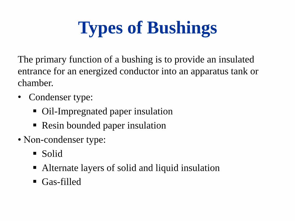
Types of Bushings
The primary function of a bushing is to provide an insulated
entrance for an energized conductor into an apparatus tank or
chamber.
• Condenser type:
Oil-Impregnated paper insulation
Resin bounded paper insulation
• Non-condenser type:
Solid
Alternate layers of solid and liquid insulation
Gas-filled

Bushing
• For outdoor bushings, the primary insulation is contained in a weather-proof housing, usually porcelain.
• The space between the primary insulation and the weather shed is generally filled with an insulating oil or compound (also used are plastic and foam).
• Some of the solid homogeneous types may use oil to fill the space between the conductor and the inner wall of the weather-shed.
• Bushings also may use gas, such as SF6 as an insulating medium between the center conductor and outer weather-shed.
• Bushings may be further classified generally as being equipped, or not equipped, with a potential tap or power-factor test tap or electrode.
• NOTE “Potential” taps are sometimes also referred to as “capacitance” or “voltage” taps.

Bushing Components

C11
C12
C13
C14
C1
C2
Anatomy of a
Condenser Bushing

Condenser Bushing Construction


Bushing Core Designs

Bushing Test Tap Example

Bushing Potential Tap Example
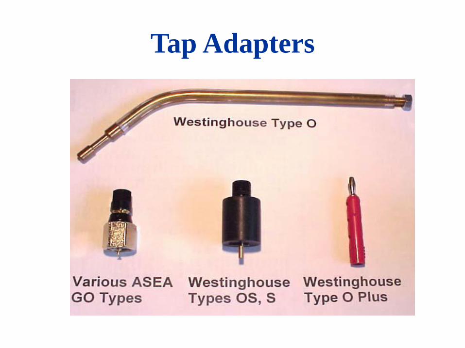
Tap Adapters
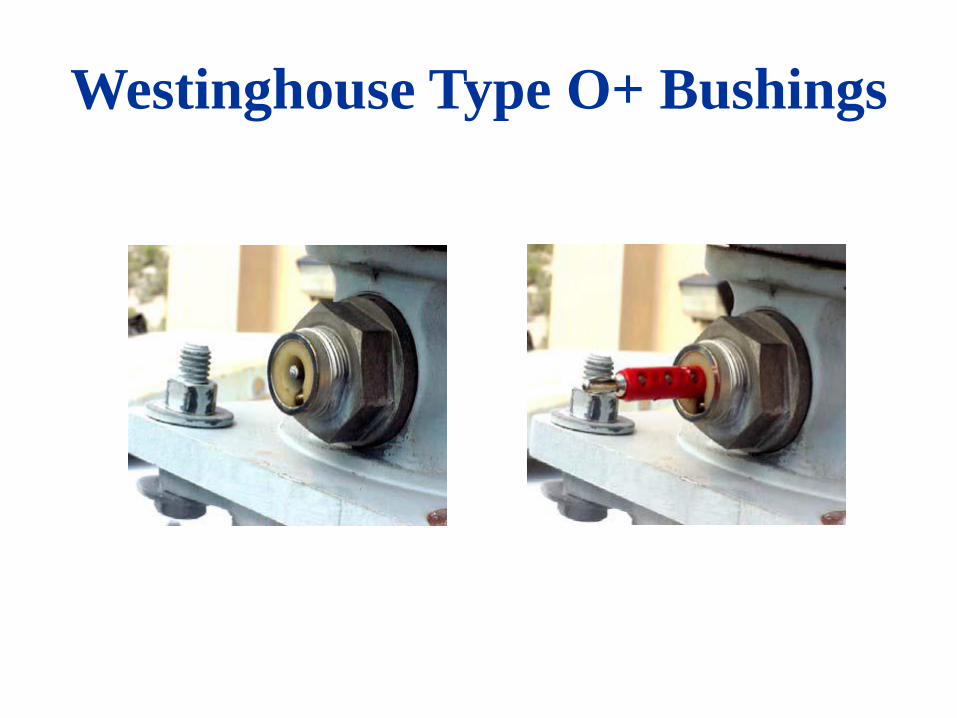
Westinghouse Type O+ Bushings

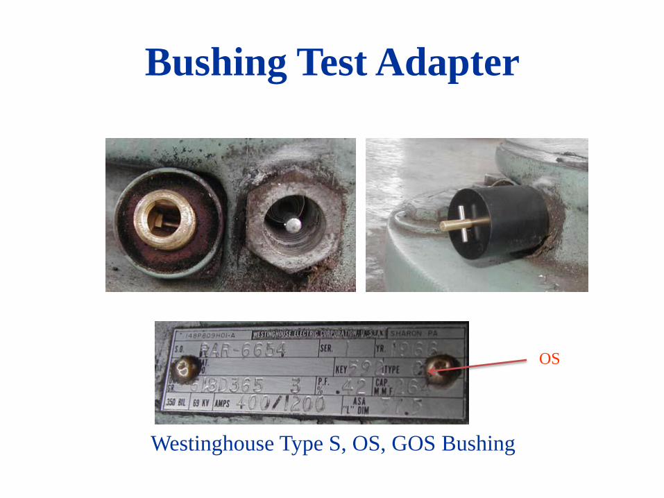
Bushing Test Adapter
Westinghouse Type S, OS, GOS Bushing
Bushing Test Adapter
OS
Westinghouse Type S, OS, GOS Bushing
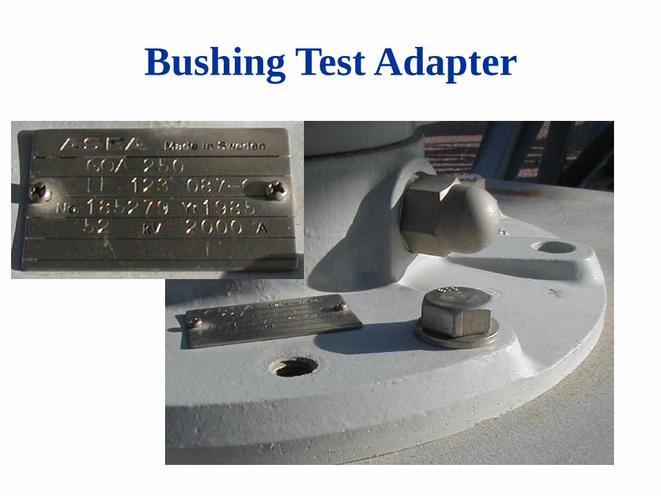
Bushing Test Adapter

Bushing Test Adapter
Bushing Troubles
• Operating records show that about 90 percent of all preventable bushing failures are caused by moisture entering the bushing through leaky gaskets or other openings.
• High-voltage bushings, if allowed to deteriorate, may explode with considerable violence and cause extensive damages to adjacent equipment.
• Flashovers may be caused by deposits of dirt on the bushings, particularly in areas where there are contaminants such as salts or conducting dusts in the air. These deposits should be removed by periodic cleaning.
Bushing Tests
• Ungrounded-Specimen Test (center conductor to tap, C1). • Tap Insulation Test (tap to flange, C2) • Collar Test (externally applied collar to center conductor) • Overall (center conductor to flange) • Inverse Ungrounded-Specimen Test (tap to center conductor, C1. Do not exceed tap voltage rating!) • Tip-up Test (repeat C1 at 2 and 10 kV or 2 and L-G kV if less than 10)
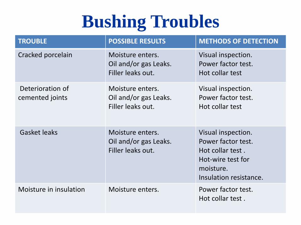
Bushing Troubles TROUBLE POSSIBLE RESULTS METHODS OF DETECTION
Cracked porcelain Moisture enters. Oil and/or gas Leaks. Filler leaks out.
Visual inspection. Power factor test. Hot collar test
Deterioration of cemented joints
Moisture enters. Oil and/or gas Leaks. Filler leaks out.
Visual inspection. Power factor test. Hot collar test
Gasket leaks Moisture enters. Oil and/or gas Leaks. Filler leaks out.
Visual inspection. Power factor test. Hot collar test . Hot-wire test for moisture. Insulation resistance.
Moisture in insulation Moisture enters.
Power factor test. Hot collar test .

Bushing Troubles TROUBLE POSSIBLE RESULTS METHODS OF DETECTION
Solder seal leak Moisture enters. Filler leaks out.
Visual inspection. Power factor test. Hot collar test . Hot-wire test for moisture. Leak detector
Broken connection between ground sleeve and flange
Moisture enters. Oil and/or gas Leaks. Filler leaks out.
Visual inspection. Power factor test. Hot collar test
Gasket leaks Sparking in apparatus Tank or within bushing. Discolored oil.
Power factor test.
Voids in compound Internal corona. Power factor Tip up test. Hot collar test .

Bushing Troubles TROUBLE POSSIBLE RESULTS METHODS OF DETECTION
Oil migration Filler contamination Visual inspection. Power factor test. Hot collar test .
No Oil Oil leaks out Moisture enters.
Visual inspection. Power factor test. Hot collar test.
Displaced grading shield. Internal sparking discolors oil.
Hot collar test .
Electrical flashover Cracked or broken porcelain. Complete failure.
Visual inspection. Hot collar test .
Lightning Cracked or broken porcelain. Complete failure.
Visual inspection. Test lightning arrester

Bushing Troubles
TROUBLE POSSIBLE RESULTS METHODS OF DETECTION
corona Internal breakdown. Radio interference. Treeing along surface of paper or internal surfaces.
Power factor test Hot collar test. Hot-wire test. RRIV
Short-circuited condenser sections
Increased capacitance. Reduced voltage at capacitance tap terminal. Adds internal stress to insulation.
Power factor test. Voltage test at capacitance tap. Capacitance test.
Darkened oil Radio interference, Poor test results.
Power factor test. Hot collar test.

Preparing for
Tests

Bushing Cleaning
Recommendations: • Collinite Wax • Clean, dry cloth • Soap & Water !! • Windex with Ammonia • Apply heat (lamp) to fully dry all surfaces
Alcohol NOT recommended

Spare Bushings
Do not test in a wooden crate (capacitive coupling) Support on a metal stand if possible If hanging from a sling, the sling’s cleanliness may affect the test, and it
should be kept away from energized points Connect ground lead directly to bushing flange, and ground both test set
and the specimen to adequate ground Clean upper and lower surfaces before testing

Bushing C1 (conductor to tap)
Insulation Test
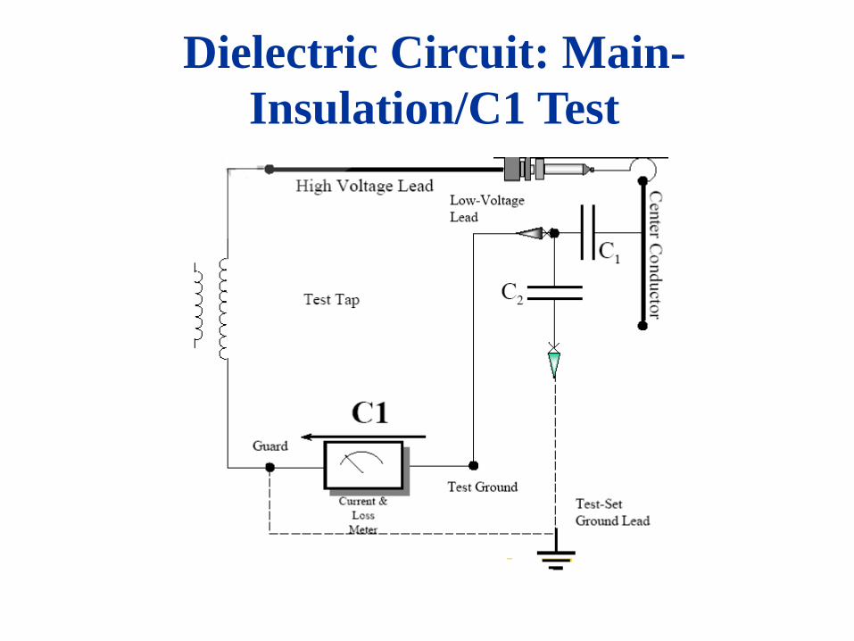
Dielectric Circuit: Main-
Insulation/C1 Test

Dielectric Circuit: C2 Insulation

Bushing Tap-Insulation (C2) Test

Test Result Analysis
Bushing Power Factor •C1 power factor for modern condenser type bushings are typically near 0.5% after correction to 20 degrees C. •C2 should be <1.0% PF for condenser and <2.0% for non-paper/oil filled bushings. • C2 insulation greater than a 1.0% power factor is questionable and warrants further investigation.
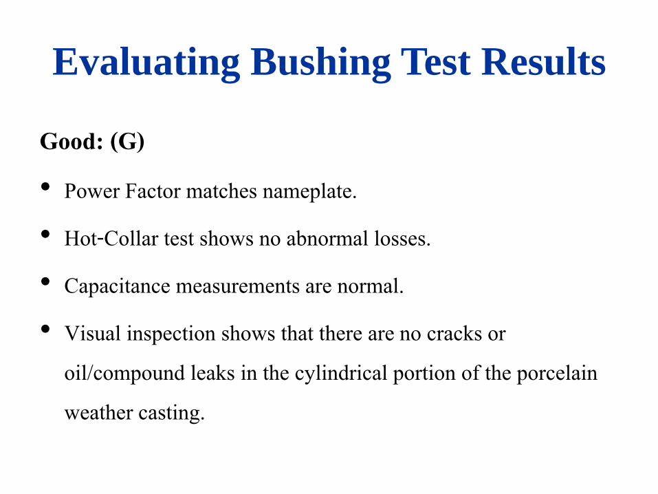
Evaluating Bushing Test Results
Good: (G) • Power Factor matches nameplate. • Hot-Collar test shows no abnormal losses. • Capacitance measurements are normal. • Visual inspection shows that there are no cracks or
oil/compound leaks in the cylindrical portion of the porcelain weather casting.

Evaluating Bushing Test Results
Deteriorated: (D) • Overall GST and/or UST power factors are approximately
twice the nameplate values for a new bushing, and/or the Hot-Collar test values are deteriorated.
• If a visual inspection shows that compound is leaking from the bushing in the vicinity of a gasket, this fact should be recorded on the test data sheet. A defective gasket will eventually permit moisture to enter.

Evaluating Bushing Test Results Ct.
Investigate: (I) • If power factor is significantly different than nameplate value
and overall GST or UST value is greater than 1.0 %PF. • If Hot-Collar test values are abnormal. • If the capacitance is abnormal.
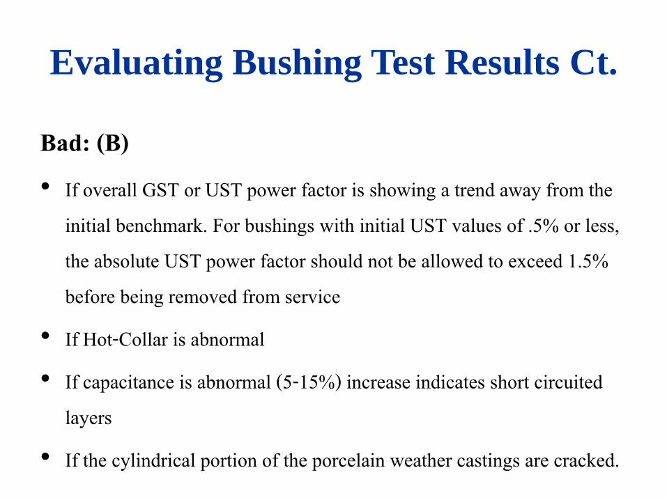
Evaluating Bushing Test Results Ct.
Bad: (B) • If overall GST or UST power factor is showing a trend away from the
initial benchmark. For bushings with initial UST values of .5% or less, the absolute UST power factor should not be allowed to exceed 1.5% before being removed from service
• If Hot-Collar is abnormal • If capacitance is abnormal (5-15%) increase indicates short circuited
layers • If the cylindrical portion of the porcelain weather castings are cracked.

Variation Of Power Factor with
Temperature
• Electrical characteristics of all insulating materials vary with temperature.
• In order to compare results of periodic tests on the same apparatus while at different temperatures, it is necessary that the manner in which the results vary with temperature be known.
• The results then can be converted to a common temperature base.

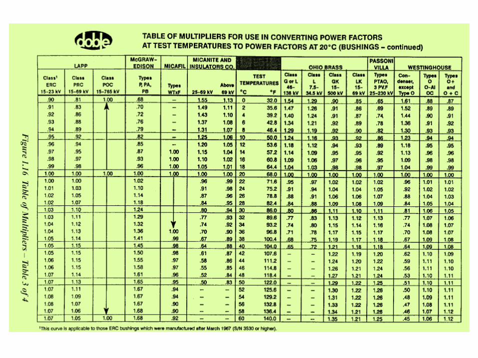
Temperature Factor Correction
Temperature-Correction is used in the following manner: 1. Calculate the specimen (e.g., bushing) power factor.
2. Determine the test-specimen temperature.
3. Obtain the appropriate correction factor from the Temperature-Correction Table corresponding to the specimen temperature.
4. Multiply (1) and (3)
Example Ohio Brass Company bushing Class GK, 115 kV
(1) Calculated power factor = 0.42%
(2) Ambient temperature = 30°C
(3) Multiplier from the Temperature-Correction Table at
30°C = 1.11
(4) Corrected to 20°C power factor = 0.42% x 1.11 = 0.47%