18
Amphenol Amphenol PCD Shenzhen www.amphenolpcd.com.cn ExcelMate CC High Voltage Coupler Outlet
AmphenolAmphenol PCD Shenzhen
www.amphenolpcd.com.cn
ExcelMate CC High Voltage Coupler Outlet
1
CONTENT
PRODUCT INTRODUCTION .…….....................……..........………………........... 2
TEChNICIal ChaRaCTERIsTICs. ...……...............................….….................. 3ElECTRIC vEhIClE ChaRgINg MODEs aND COUPlER TyPEs……………. 4
aC INsERT aRRaNgEMENT...………....................….....….……........................ 5aC vEhIClE COUPlER INTERfaCE..........…………………………................... 6PlUg aND sOCkET OUTlET.............................................................................. 7aC COUPlER DIMENsIONs…………………….......…........................................ 8MOUNTINg INsTRUCTIONs...………….…………............................................. 9
DC INsERT aRRaNgEMENT............................................................................... 10DC ChaRgINg COUPlER INTERfaCE...……………………………………….… 1180a DC COUPlER DIMENsION……………………………………………............. 12120a TO 250a DC COUPlER DIMENsION………………………………….......... 13
PRODUCT faMIly…………………..............................…..................…………… 14
hOW TO ORDER.................................................................................................. 15
2
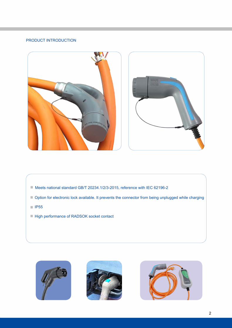
PRODUCT INTRODUCTION
Meets national standard gB/T 20234.1/2/3-2015, reference with IEC 62196-2
Option for electronic lock available. It prevents the connector from being unplugged while charging
IP55
high performance of RaDsOk socket contact
3
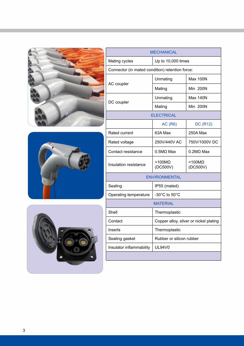
MEChaNICal
Mating cycles Up to 10,000 times
Connector (in mated condition) retention force:
aC coupler Unmating Max 100N
Mating Min 200N
DC couplerUnmating Max 140N
Mating Min 200N
ElECTRICal
aC (R6) DC (R12)
Rated current 63a Max 250a Max
Rated voltage 250v/440v aC 750v/1000v DC
Contact resistance 0.5MΩ Max 0.2MΩ Max
Insulation resistance >100MΩ (DC500v)
>100MΩ(DC500v)
ENvIRONMENTal
sealing IP55 (mated)
Operating temperature -30°C to 50°C
MaTERIal
shell Thermoplastic
Contact Copper alloy, silver or nickel plating
lnserts Thermoplastic
sealing gasket Rubber or silicon rubber
Insulator inflammability Ul94v0
4
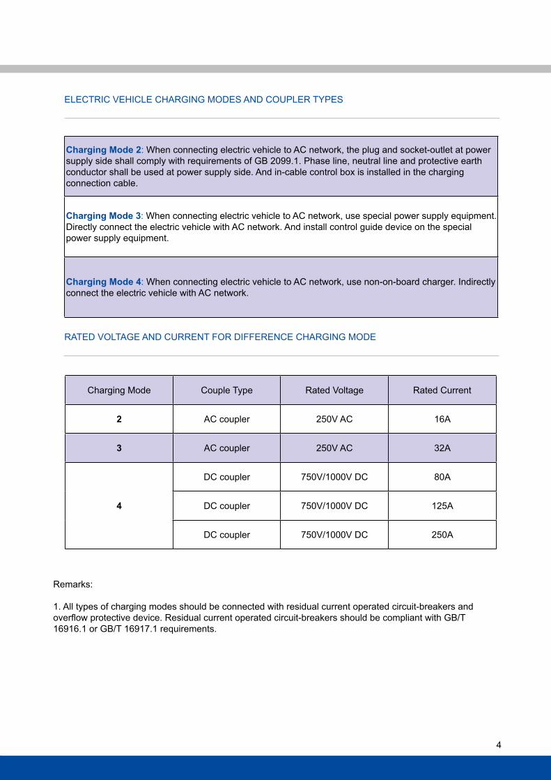
ElECTRIC vEhIClE ChaRgINg MODEs aND COUPlER TyPEs
RaTED vOlTagE aND CURRENT fOR DIffERENCE ChaRgINg MODE
Charging Mode Couple Type Rated voltage Rated Current
2 aC coupler 250v aC 16a
3 aC coupler 250v aC 32a
4
DC coupler 750v/1000v DC 80a
DC coupler 750v/1000v DC 125a
DC coupler 750v/1000v DC 250a
Remarks:
1. all types of charging modes should be connected with residual current operated circuit-breakers and overflow protective device. Residual current operated circuit-breakers should be compliant with GB/T 16916.1 or gB/T 16917.1 requirements.
Charging Mode 2: When connecting electric vehicle to aC network, the plug and socket-outlet at power supply side shall comply with requirements of gB 2099.1. Phase line, neutral line and protective earth conductor shall be used at power supply side. and in-cable control box is installed in the charging connection cable.
Charging Mode 3: When connecting electric vehicle to aC network, use special power supply equipment. Directly connect the electric vehicle with aC network. and install control guide device on the special power supply equipment.
Charging Mode 4: When connecting electric vehicle to aC network, use non-on-board charger. Indirectly connect the electric vehicle with aC network.
5
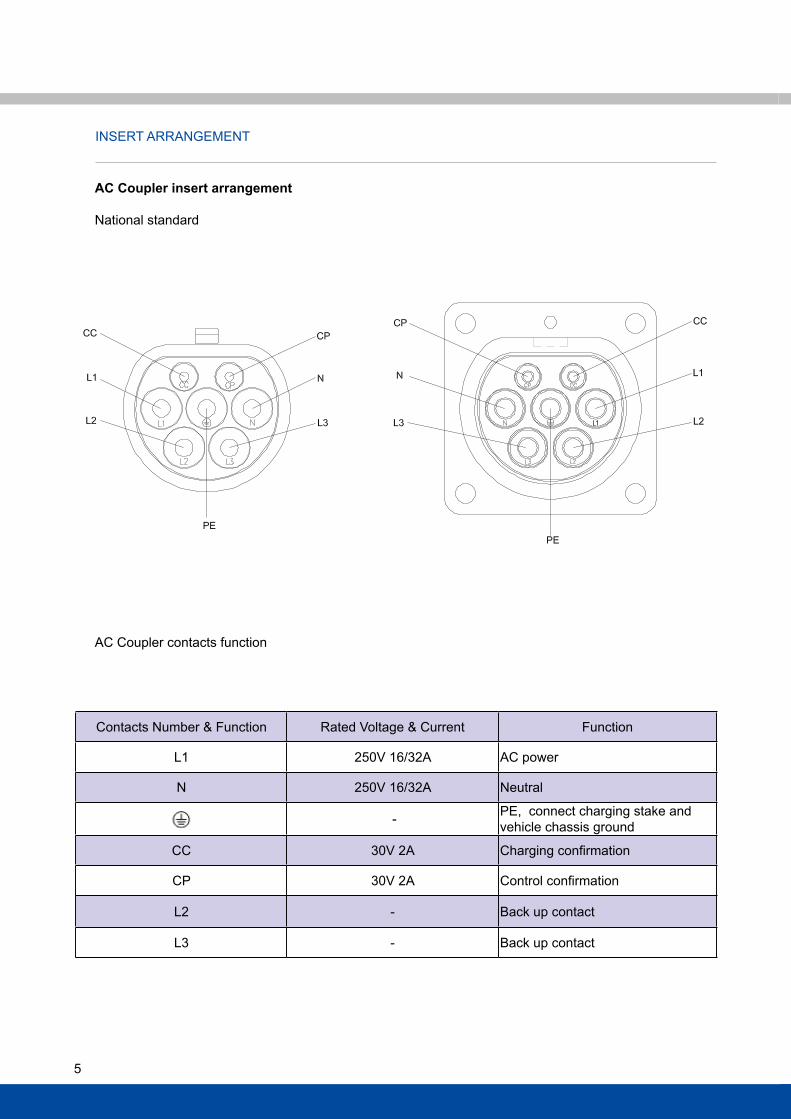
INsERT aRRaNgEMENT
aC Coupler contacts function
AC Coupler insert arrangement
National standard
Contacts Number & function Rated voltage & Current function
l1 250v 16/32a aC power
N 250v 16/32a Neutral
- PE, connect charging stake and vehicle chassis ground
CC 30v 2a Charging confirmation
CP 30v 2a Control confirmation
l2 - Back up contact
l3 - Back up contact
6
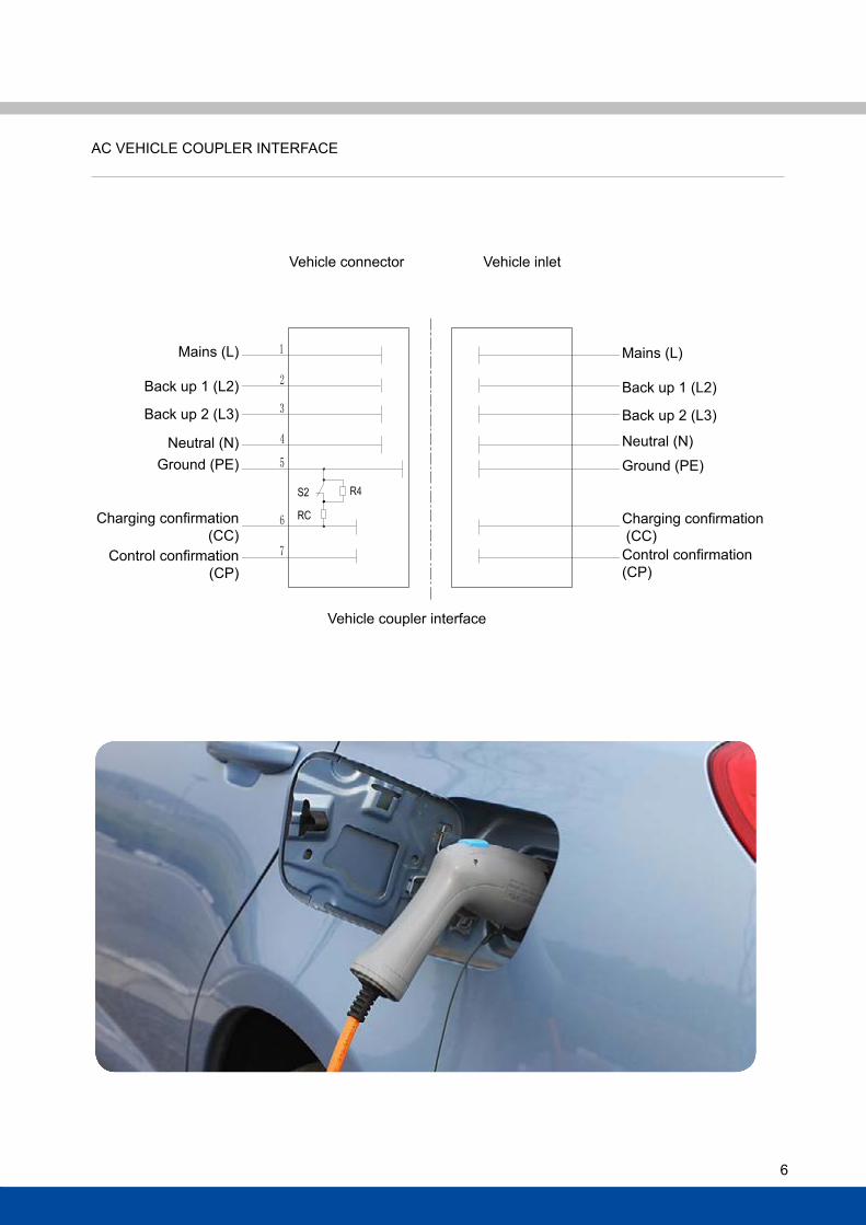
aC vEhIClE COUPlER INTERfaCE
vehicle connector
vehicle coupler interface
vehicle inlet
Mains (l)
Back up 1 (l2)
Back up 2 (l3)
Neutral (N)ground (PE)
Charging confirmation (CC)
Control confirmation(CP)
Mains (l)
Back up 1 (l2)
Back up 2 (l3)
Neutral (N)
ground (PE)
Charging confirmation (CC)Control confirmation(CP)
7
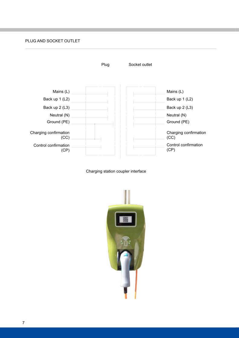
PlUg aND sOCkET OUTlET
Plug
Charging station coupler interface
socket outlet
Mains (l)
Back up 1 (l2)
Back up 2 (l3)
Neutral (N)
ground (PE)
Charging confirmation (CC)
Control confirmation(CP)
Mains (l)
Back up 1 (l2)
Back up 2 (l3)
Neutral (N)
ground (PE)
Charging confirmation (CC)
Control confirmation(CP)
8
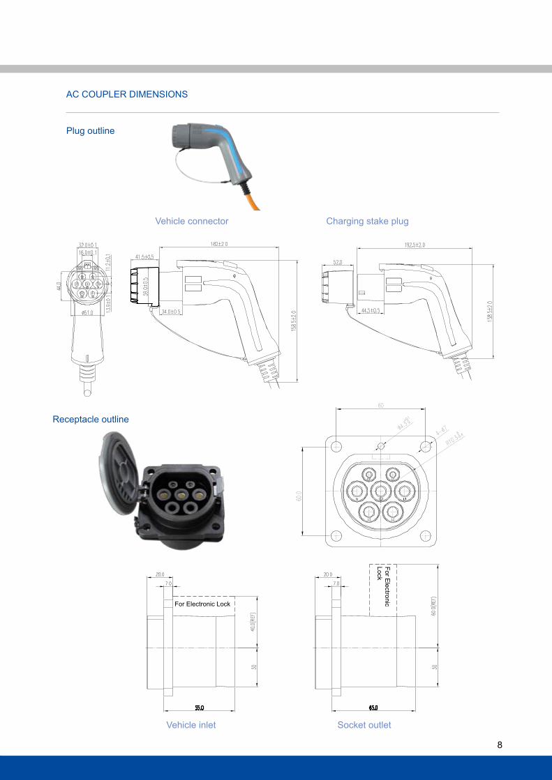
Plug outline
Receptacle outline
aC COUPlER DIMENsIONs
vehicle inlet socket outlet
Charging stake plugvehicle connector
for Electronic lock
for Electronic
lock
9
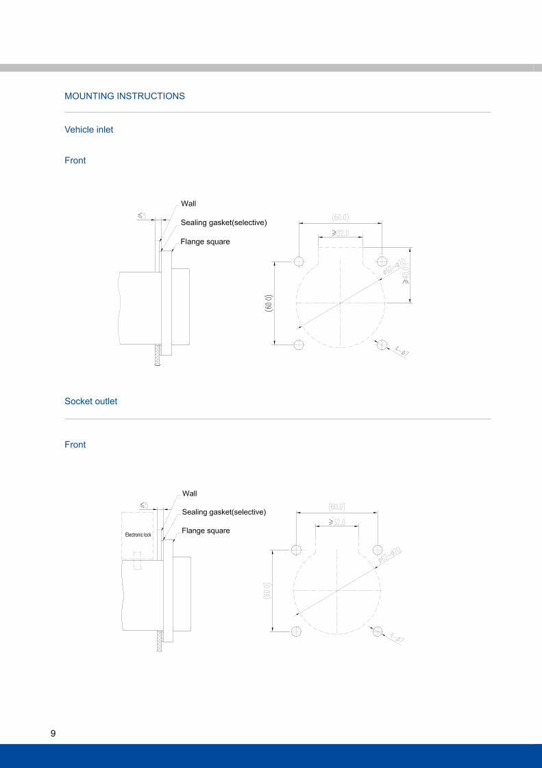
MOUNTINg INsTRUCTIONs
vehicle inlet
socket outlet
front
front
10
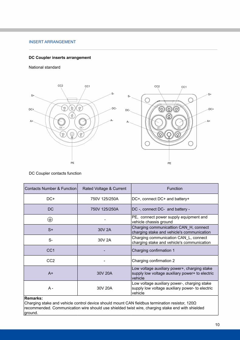
INsERT aRRaNgEMENT
DC Coupler contacts function
DC Coupler inserts arrangement
National standard
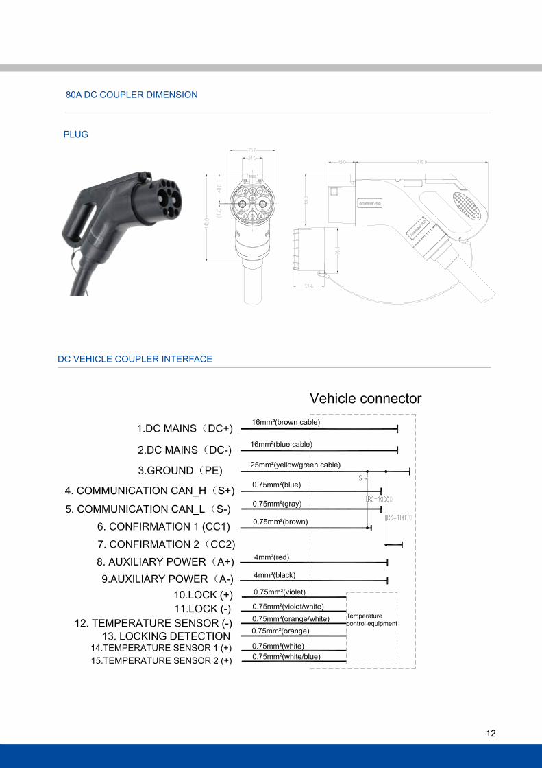
Contacts Number & function Rated voltage & Current function
DC+ 750v 125/250a DC+, connect DC+ and battery+
DC 750v 125/250a DC -, connect DC- and battery -
- PE, connect power supply equipment and vehicle chassis ground
s+ 30v 2a Charging communicattion CaN_h, connect charging stake and vehicle's communication
s- 30v 2a Charging communication CaN_l, connect charging stake and vehicle's communication
CC1 - Charging confirmation 1
CC2 - Charging confirmation 2
a+ 30v 20alow voltage auxiliary power+, charging stake supply low voltage auxiliary power+ to electric vehicle
a - 30v 20alow voltage auxiliary power-, charging stake supply low voltage auxiliary power- to electric vehicle
Remarks: Charging stake and vehicle control device should mount CAN fieldbus termination resistor, 120Ω recommended. Communication wire should use shielded twist wire, charging stake end with shielded ground.
11
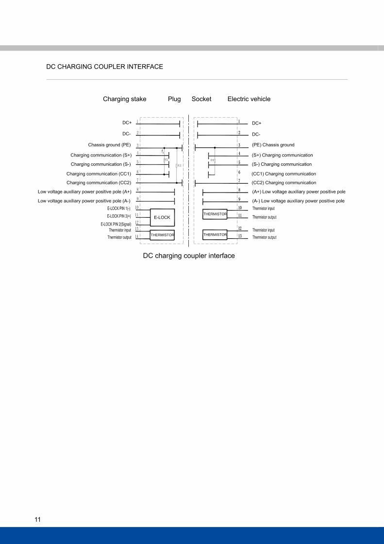
DC ChaRgINg COUPlER INTERfaCE
Charging stake Plug socket Electric vehicle
12
DC vEhIClE COUPlER INTERfaCE
PlUg
80a DC COUPlER DIMENsION
Temperaturecontrol equipment
13
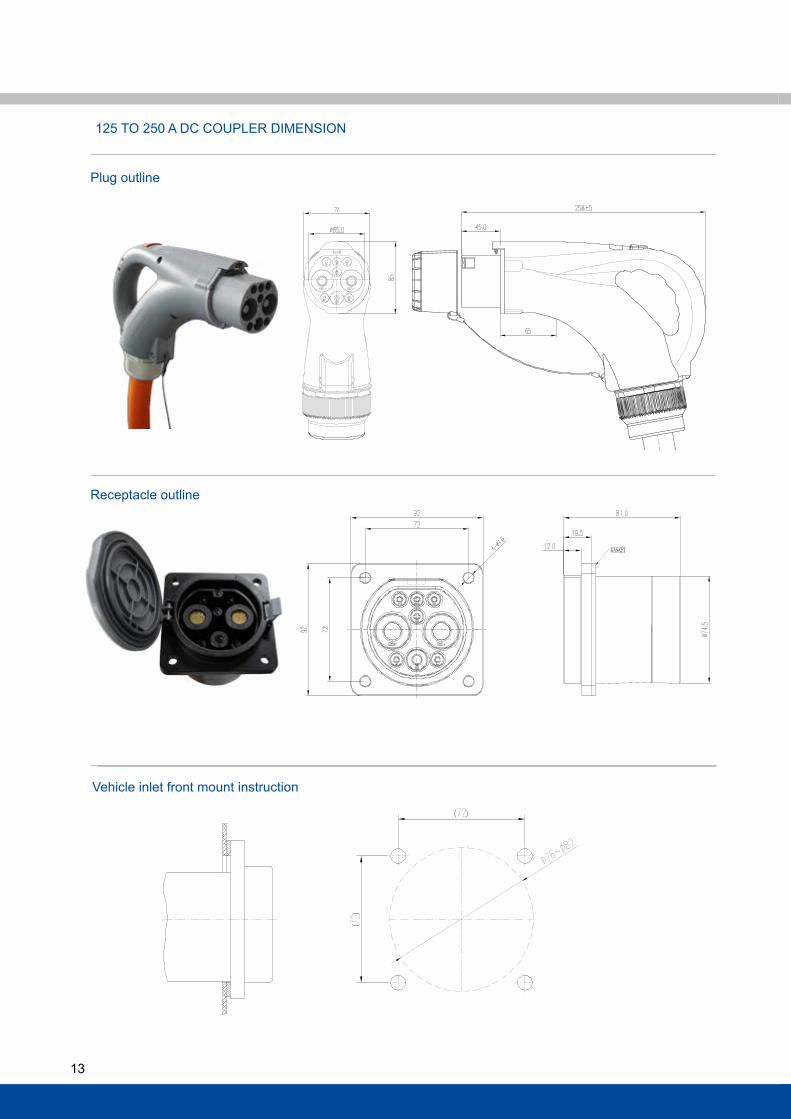
Plug outline
Receptacle outline
125 TO 250 a DC COUPlER DIMENsION
vehicle inlet front mount instruction
14
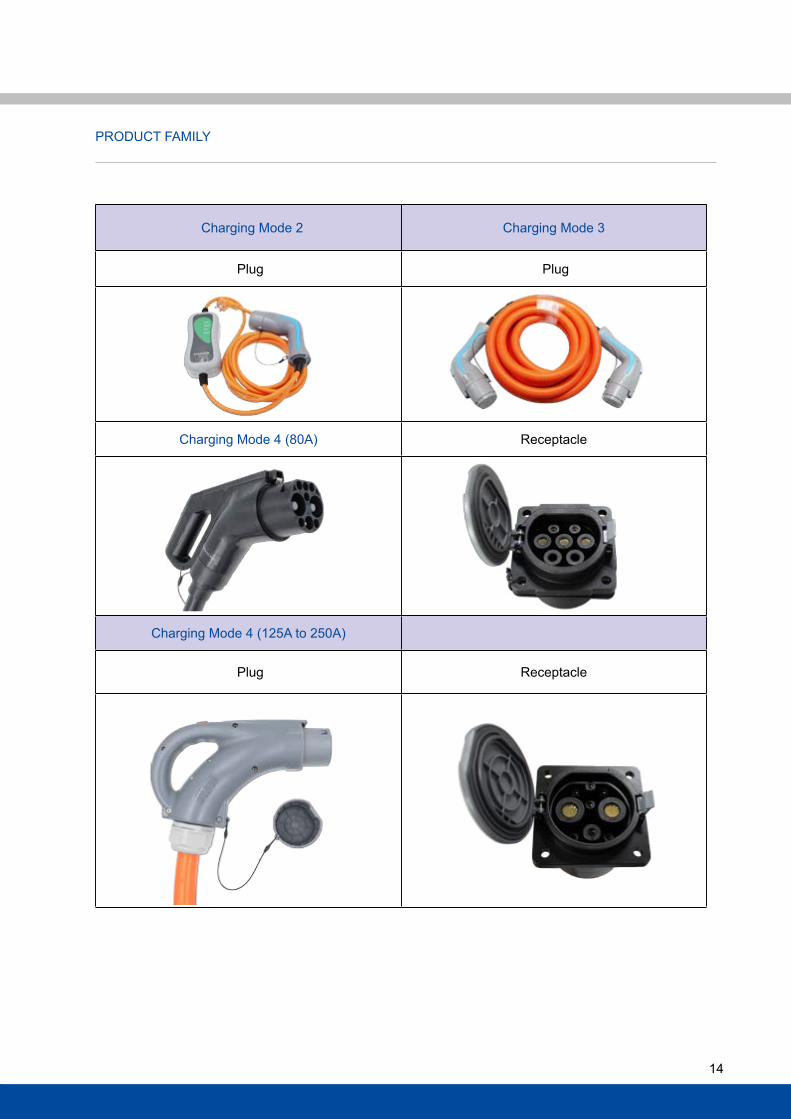
PRODUCT faMIly
Charging Mode 2 Charging Mode 3
Plug Plug
Charging Mode 4 (80a) Receptacle
Charging Mode 4 (125a to 250a)
Plug Receptacle
15
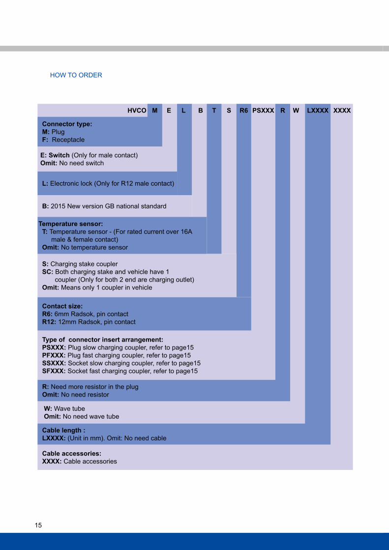
HVCO M E L B T S R6 PSXXX R W LXXXX XXXX
Connector type: M: Plug F: Receptacle
E: Switch (Only for male contact) Omit: No need switch
L: Electronic lock (Only for R12 male contact)
B: 2015 New version gB national standard
Temperature sensor: T: Temperature sensor - (for rated current over 16a male & female contact) Omit: No temperature sensor
S: Charging stake coupler SC: Both charging stake and vehicle have 1 coupler (Only for both 2 end are charging outlet) Omit: Means only 1 coupler in vehicle
Contact size: R6: 6mm Radsok, pin contact R12: 12mm Radsok, pin contact
Type of connector insert arrangement: PSXXX: Plug slow charging coupler, refer to page15 PFXXX: Plug fast charging coupler, refer to page15 SSXXX: socket slow charging coupler, refer to page15 SFXXX: socket fast charging coupler, refer to page15
R: Need more resistor in the plug Omit: No need resistor
W: Wave tube Omit: No need wave tube
Cable length : LXXXX: (Unit in mm). Omit: No need cable
Cable accessories: XXXX: Cable accessories
hOW TO ORDER
16
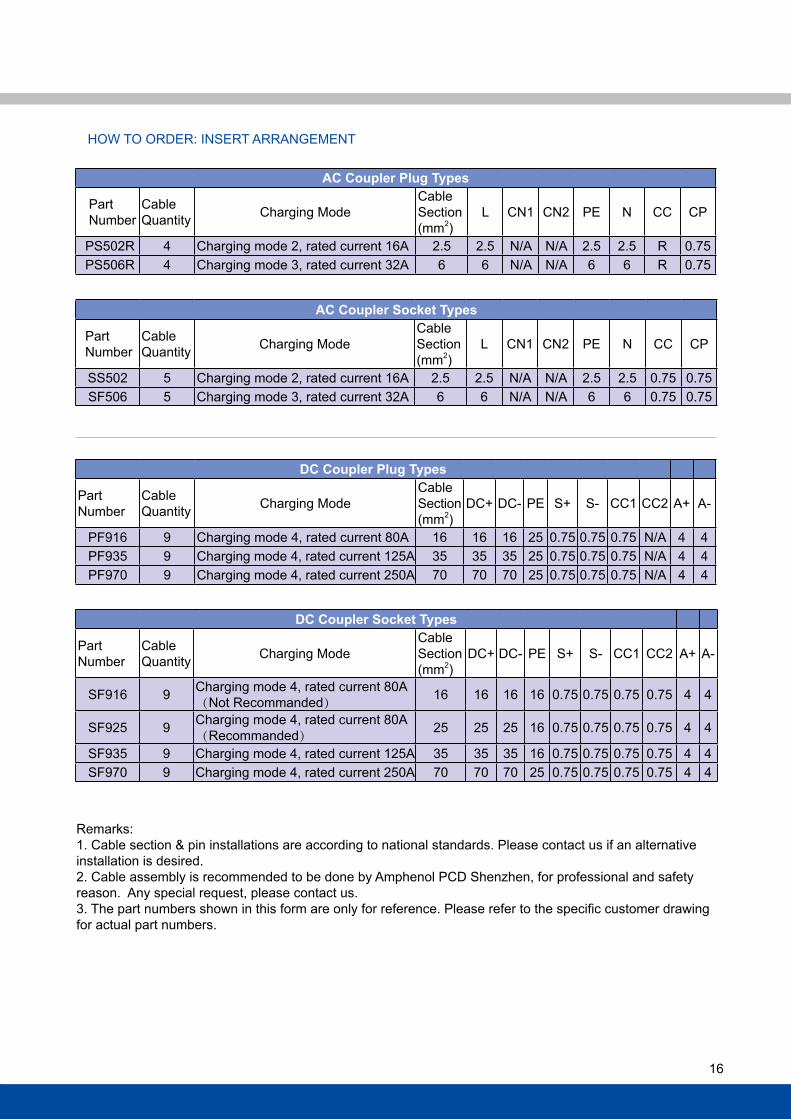
hOW TO ORDER: INsERT aRRaNgEMENT
AC Coupler Plug Types
Part Number
Cable quantity Charging Mode
Cable section (mm2)
l CN1 CN2 PE N CC CP
Ps502R 4 Charging mode 2, rated current 16a 2.5 2.5 N/a N/a 2.5 2.5 R 0.75 Ps506R 4 Charging mode 3, rated current 32a 6 6 N/a N/a 6 6 R 0.75
AC Coupler Socket Types
Part Number
Cable quantity Charging Mode
Cable section (mm2)
l CN1 CN2 PE N CC CP
ss502 5 Charging mode 2, rated current 16a 2.5 2.5 N/a N/a 2.5 2.5 0.75 0.75sf506 5 Charging mode 3, rated current 32a 6 6 N/a N/a 6 6 0.75 0.75
DC Coupler Plug Types
Part Number
Cable quantity Charging Mode
Cable section (mm2)
DC+ DC- PE s+ s- CC1 CC2 a+ a-
Pf916 9 Charging mode 4, rated current 80a 16 16 16 25 0.75 0.75 0.75 N/a 4 4Pf935 9 Charging mode 4, rated current 125a 35 35 35 25 0.75 0.75 0.75 N/a 4 4Pf970 9 Charging mode 4, rated current 250a 70 70 70 25 0.75 0.75 0.75 N/a 4 4
DC Coupler Socket Types
Part Number
Cable quantity Charging Mode
Cable section (mm2)
DC+ DC- PE s+ s- CC1 CC2 a+ a-
sf916 9 Charging mode 4, rated current 80a(Not Recommanded) 16 16 16 16 0.75 0.75 0.75 0.75 4 4
sf925 9 Charging mode 4, rated current 80a(Recommanded) 25 25 25 16 0.75 0.75 0.75 0.75 4 4
sf935 9 Charging mode 4, rated current 125a 35 35 35 16 0.75 0.75 0.75 0.75 4 4sf970 9 Charging mode 4, rated current 250a 70 70 70 25 0.75 0.75 0.75 0.75 4 4
Remarks:1. Cable section & pin installations are according to national standards. Please contact us if an alternative installation is desired.2. Cable assembly is recommended to be done by amphenol PCD shenzhen, for professional and safety reason. any special request, please contact us.3. The part numbers shown in this form are only for reference. Please refer to the specific customer drawing for actual part numbers.
Notes:
amphenol PCD shenzhen has made every effort to ensure that the information contained in this catalog is accurate at the time of publication. Specifications or information stated in this publication are subject to change without notice.
amphenol PCD shenzhen reserves the right to clarify this catalog.
amphenol PCD shenzhen Building 211st liao keng Industrial Zoneshi yan street, Bao an District shenzhen 518108China
TTel.: +86 755-8173-8000fax: +86 755-8173-8180Email: [email protected]
www.amphenolpcd.com.cn


