59
High Voltage Embedded Generation Network Access Standard UE-ST-2008. 3
High Voltage Embedded Generation Network Access
Standard UE-ST-2008.3

High Voltage Embedded Generation Network Access Standard | UE-ST-2008.3 Page 1 of 56
Disclaimer The master document is controlled electronically.
Ensure latest version prior to use.
Based on document template: UE-TP-5140 Standard Revision 190826. Document controlled in accordance with UE-ST-1750 INMS Document Management Standard.

High Voltage Embedded Generation Network Access Standard | UE-ST-2008.3 Page 2 of 56
Document Control
Reviewer Title Signature
Darshana Paranagama Principal Engineer Complex Customer Connections {{Sig_es_:signer2:signature}}
Christopher Roberts Principal Engineer Network Planning {{Sig_es_:signer3:signature}}
Approver Title Signature
Roshanth Sivanathan Head of Network Planning {{Sig_es_:signer4:signature}}
Robert Simpkin Secondary Assets Manager {{Sig_es_:signer5:signature}}
Version Amendment Overview Author
1 Supersedes UE-ST-2008
Incorporates ENA National DER Grid Connection Guidelines – Technical Guidelines for Medium and High Voltage EG Connections
Sarah Lim Technical Consultant 31st July 2020
Kaisui Tnay Engineer Complex Customer Connections 31st July 2020
1.1 Updated the following sections:
Section 1.3 (7), Section 5.3.2, Section 5.7.2.2 Remote Trip Scheme, Section 5.7.3, Section 6 Table 11, Section 8.3.1, Section 8.3.1.1, Section 8.3.2, Section 8.6.2.1, Section 8.6.2.2 Remote Trip Scheme, Section 8.6.3, Section 9 Table 18
Kaisui Tnay Senior Engineer Complex Customer Connections
{{Sig_es_:signer1:signature}}
Kaisui Tnay (Dec 16, 2020 11:06 GMT+11)Kaisui Tnay
Darshana Paranagama (Dec 16, 2020 12:13 GMT+11)Darshana Paranagama
Christopher Roberts (Dec 16, 2020 13:18 GMT+11)Christopher Roberts
Rosh Sivanathan (Dec 21, 2020 15:23 GMT+11)Rosh Sivanathan
Robert Simpkin (Dec 21, 2020 16:05 GMT+11)Robert Simpkin

High Voltage Embedded Generation Network Access Standard | UE-ST-2008.3 Page 3 of 56
Table of Contents Document Control ........................................................................................................................................................ 2 1. Introduction .......................................................................................................................................................... 7
1.1 Purpose of document .............................................................................................................................. 7 1.1.1 HV EG IES Connection Limits.................................................................................................................... 8 1.1.2 HV non-IES EG Connection Limits ............................................................................................................. 9 1.1.3 Combined HV EG IES and Non-IES System .............................................................................................. 9 1.2 Scope .................................................................................................................................................... 10 1.3 Obligations ............................................................................................................................................ 10 1.4 UE HV EG Assessment Considerations................................................................................................ 11
2. Definitions and Abbreviations ........................................................................................................................... 12 2.1 Definitions ............................................................................................................................................. 12 2.2 Abbreviations ........................................................................................................................................ 14 2.3 Terminology .......................................................................................................................................... 16 2.3.1 Subcategories ......................................................................................................................................... 16
3. Relevant Rules, Regulations, Standards and Codes ......................................................................................... 17 3.1 Standards and Codes ............................................................................................................................ 17 3.2 Legislation and Regulation ................................................................................................................... 18
4. Fees and Charges .............................................................................................................................................. 18 5. Technical Requirements for HV EG IES ............................................................................................................. 20
5.1 Labelling and Signage .......................................................................................................................... 20 5.2 Maximum System Capacity ................................................................................................................... 20 5.3 Generation Control................................................................................................................................ 20 5.3.1 Export Limits at Connection Point ............................................................................................................ 20 5.3.2 Anti-Islanding Considerations .................................................................................................................. 20 5.3.3 Network Asset Constraints Considerations ............................................................................................... 20 5.3.4 Site Generation Limit Downstream of Connection Point ............................................................................ 20 5.4 Inverter Energy System......................................................................................................................... 21 5.5 Network Connection and Isolation........................................................................................................ 21 5.6 Earthing ................................................................................................................................................. 21 5.7 Protection .............................................................................................................................................. 22 5.7.1 Protection Requirements at HV Point of Connection (POC) ...................................................................... 22 5.7.2 IES Protection ......................................................................................................................................... 22 5.7.2.1 Inverter Integrated Protection .................................................................................................................. 22 5.7.2.2 IES Backup Protection............................................................................................................................. 23 5.7.3 Special Operational Conditions ................................................................................................................ 26 5.7.4 Switchgear and control gear requirements ............................................................................................... 27 5.7.5 Interlocking ............................................................................................................................................. 27 5.8 Operating Voltage and Frequency ........................................................................................................ 27 5.9 Metering ................................................................................................................................................ 28 5.10 Power Quality ........................................................................................................................................ 28 5.10.1 IES Volt Response Modes ....................................................................................................................... 28 5.10.2 Network Ancillary Services ...................................................................................................................... 28

High Voltage Embedded Generation Network Access Standard | UE-ST-2008.3 Page 4 of 56
5.11 HV Embedded Network ......................................................................................................................... 28 5.12 Communications Requirements for Monitoring Systems .................................................................... 28 5.13 Data and Information............................................................................................................................. 29 5.13.1 Static Data and Information ..................................................................................................................... 29 5.13.2 Dynamic Data and Information ................................................................................................................. 29 5.14 Cybersecurity ........................................................................................................................................ 29 5.15 Technical Studies .................................................................................................................................. 29 5.15.1 Power Flow Study ................................................................................................................................... 30 5.15.2 Power Quality Impact Studies .................................................................................................................. 30 5.15.3 Fault Level Contribution Study and Protection Settings Report .................................................................. 30 5.15.4 Earthing Study ........................................................................................................................................ 30 5.15.5 System studies........................................................................................................................................ 30
6. Testing and Commissioning for HV EG IES ....................................................................................................... 32 7. Operations and Maintenance ............................................................................................................................. 34 8. Technical Requirements for HV non-IES EG ..................................................................................................... 36
8.1 Labelling and Signage .......................................................................................................................... 36 8.2 Maximum System Capacity ................................................................................................................... 36 8.3 Generation Control................................................................................................................................ 36 8.3.1 Export Constraints at Connection Point .................................................................................................... 36 8.3.1.1 Anti-Islanding Considerations .................................................................................................................. 36 8.3.1.2 Network Asset Constraints Considerations ............................................................................................... 36 8.3.2 Site Generation Limit Downstream of Connection Point ............................................................................ 36 8.4 Network Connection and Isolation........................................................................................................ 37 8.5 Earthing ................................................................................................................................................. 37 8.6 Protection .............................................................................................................................................. 37 8.6.1 Protection Requirements at HV Point of Connection (POC) ...................................................................... 37 8.6.2 HV non-IES EG Protection ...................................................................................................................... 37 8.6.2.1 HV non-IES EG Integrated Protection ...................................................................................................... 38 8.6.2.2 Backup Protection ................................................................................................................................... 38 8.6.3 Special Operational Conditions ................................................................................................................ 42 8.6.4 Switchgear and control gear requirements ............................................................................................... 42 8.6.5 Interlocking ............................................................................................................................................. 43 8.7 Operating Voltage and Frequency ........................................................................................................ 43 8.8 Metering ................................................................................................................................................ 43 8.9 Power Quality ........................................................................................................................................ 43 8.9.1 HV Non-IES Voltage Response Modes .................................................................................................... 43 8.9.2 Network Ancillary Services ...................................................................................................................... 43 8.10 HV Embedded Network ......................................................................................................................... 44 8.11 Communications Systems .................................................................................................................... 44 8.12 Data and Information............................................................................................................................. 44 8.12.1 Static Data and Information ..................................................................................................................... 44 8.12.2 Dynamic Data and Information ................................................................................................................. 44 8.13 Cybersecurity ........................................................................................................................................ 44 8.14 Technical Studies .................................................................................................................................. 45

High Voltage Embedded Generation Network Access Standard | UE-ST-2008.3 Page 5 of 56
8.14.1 Power Flow Study ................................................................................................................................... 45 8.14.2 Power Quality Impact Studies .................................................................................................................. 45 8.14.3 Fault Level Contribution Study and Protection Settings Report .................................................................. 45 8.14.4 Earthing Study ........................................................................................................................................ 45 8.14.5 System studies........................................................................................................................................ 46
9. Testing and Commissioning for HV non-IES EG ............................................................................................... 47 10. Operations and Maintenance ............................................................................................................................. 49 Appendix A: Deviations from the National DER Connection Guidelines ................................................................... 50 Appendix B: Connection Arrangement Requirements .............................................................................................. 52 Appendix C: Sample Offer to Connect ....................................................................................................................... 55 Appendix D: Static Data and Information ................................................................................................................... 56

High Voltage Embedded Generation Network Access Standard | UE-ST-2008.3 Page 6 of 56
Table of Figures Figure 1: Typical Wireless Protection Trip Scheme ................................................................................................... 24 Figure 2: Typical Remote Trip Scheme ...................................................................................................................... 25 Figure 3: Fault levels extracted from the Electricity Distribution Code ..................................................................... 27 Figure 4: Typical Remote Trip Scheme ...................................................................................................................... 41 Figure 5: Fault levels extracted from the Electricity Distribution Code ..................................................................... 42 Figure 6: Typical HV EG installation with no export limit conditions imposed ......................................................... 52 Figure 7: Typical HV EG installation with export limit conditions imposed at LV ..................................................... 53 Figure 8: Typical HV EG installation with export limit conditions imposed at HV ..................................................... 54
List of Tables Table 1: HV EG IES capacity and export limits2, 3, 4, 5.................................................................................................... 8 Table 2: HV non-IES EG capacity and export limits2, 3, 4 ............................................................................................... 9 Table 3: Applicable Standards and Codes ................................................................................................................. 17 Table 4: Applicable Legislation and Regulations ....................................................................................................... 18 Table 5: HV EG IES Protection Requirements ............................................................................................................ 22 Table 6: Inverter Integrated Protection Settings ........................................................................................................ 22 Table 7: Backup protection requirements .................................................................................................................. 23 Table 8: Voltage unbalance requirements .................................................................................................................. 24 Table 9: Passive anti-islanding protection ................................................................................................................. 25 Table 10: Technical Studies Required for HV EG IES Connections ........................................................................... 29 Table 11: Testing and Commissioning Requirements for HV EG IES Connections .................................................. 32 Table 12: Protection requirements for HV non-IES EG .............................................................................................. 37 Table 13: HV EG integrated protection requirements ................................................................................................ 38 Table 14: HV non-IES EG backup protection requirements ....................................................................................... 39 Table 15: HV non-IES EG anti-islanding protection requirements ............................................................................. 40 Table 16: Suitability of ROCOF and vector shift for HV non-IES EG.......................................................................... 40 Table 17: Technical Studies Required for HV EG IES Connections ........................................................................... 45 Table 18: Testing and Commissioning Requirements for HV non-IES EG Connections ........................................... 47 Table 19 Table of deviations from National DER Connection Guidelines ................................................................. 50
High Voltage Embedded Generation Network Access Standard | UE-ST-2008.3 Page 7 of 56
1. Introduction This document provides the technical requirements for the equipment and installation of embedded generation (EG) connections to United Energy’s (UE) high voltage (HV) distribution network. This document has been prepared based on present network conditions and is subject to change. This document complies with the ENA National Distributed Energy Resources (DER) Connection Guidelines for medium voltage and high voltage EG Connections, with the exception of UE specific requirement deviations presented in Appendix A: Deviations from the National DER Connection Guidelines.
This document shall be read in conjunction with UE-PR-2008 EG Customer Connection Procedure. UE-PR-2008 details the EG connection services offered and the application process.
1.1 Purpose of document The purpose of this document is to provide proponents of EG connections information about their obligations for connection to and interfacing with the UE HV distribution network.
A HV EG connection type is defined in Table 1 and Table 2 and subject to the following:
a. point of customer connection to UE’s network is at high voltage (HV)
b. not required to be or is exempt from being registered in the National Electricity Market (NEM)
Any person who owns, controls, or operates a generating system connected to a transmission or distribution network in the NEM must register with Australian Energy Market Operator (AEMO) as a generator, except where they meet the exemption criteria as stipulated in the National Electricity Rules (NER). UE distribution network is part of the NEM. Generators with total installed capacity of less than 5MVA are automatically exempted from registration. Generators with total installed capacity greater than 5MVA but less than 30MVA can apply for registration exemption from AEMO, which is a separate negotiation with AEMO. However, generators with total installed capacity greater than 30MVA must register. Registered embedded generators are required to comply with the generator performance standards stipulated in Chapter 5 of the National Electricity Rules which is available on the AEMC website.
c. it is intended to be connected to and is capable of operating in parallel with any part of the HV distribution network
d. it meets all other technical requirements set out in this document
e. a Certificate of Electrical Safety (CES) is issued for the installation and provided to UE
f. it consists of either Inverter Energy System (IES) or non-IES (synchronous or asynchronous EGs), and/or Energy Storage System (ESS) with a total system capacity shown in Table 1 and Table 2

High Voltage Embedded Generation Network Access Standard | UE-ST-2008.3 Page 8 of 56
1.1.1 HV EG IES Connection Limits Only proponents with IES installations greater than 30kVA can apply for HV EG connections. Please refer to UE-ST-2008.1 Basic Micro EG Network Access Standard for IES installations less than 30kVA.
Table 1: HV EG IES capacity and export limits2, 3, 4, 5
Network Connection Type Three Phase
Connections automatically exempted from registration
Connections exempted from registration by AEMO1
Minimum total installed capacity (based on maximum continuous inverter rating) > 30kVA ≥ 5MVA
Maximum total installed capacity (based on maximum continuous inverter rating) < 5MVA 5MVA ≤ capacity < 30MVA
Maximum export < 5MVA < 30MVA
Notes:
1. The proponent shall provide evidence of registration exemption granted by AEMO prior to finalising UE connection offer.
2. The figures shown in Table 1 for total installed capacity and export is subject to change depending on site specific constraints such as
• network constraints
• location of connection point to the UE network
• generator protection and control schemes and compliance to technical requirements in this document and applicable AEMO requirements for generators with total installed capacity of greater than 5MVA.
3. The capacity limits in Table 1 is the aggregate maximum continuous inverter rating installed behind the meter.
4. The maximum installed HV EG capacity shall not exceed the thermal rating of the UE’s HV connection assets.
5. The above table is subject to the technical requirements as set out in Section 5, in particular if single phase or two phase IES are installed, the current/voltage unbalance at the POC shall not exceed the values in Section 5.7.2.

High Voltage Embedded Generation Network Access Standard | UE-ST-2008.3 Page 9 of 56
1.1.2 HV non-IES EG Connection Limits Only proponents with three phase non-IES installations can apply for HV EG connections. UE does not permit single phase or two phase non-IES installation to operate in parallel with the network.
Table 2: HV non-IES EG capacity and export limits2, 3, 4
Network Connection Type Three Phase
Connections automatically exempted from registration
Connections exempted from registration by AEMO1
Maximum total installed capacity (based on maximum continuous inverter rating) < 5MVA 5MVA ≤ capacity < 30MVA
Maximum export < 5MVA < 30MVA
Notes:
1. The proponent shall provide evidence of registration exemption granted by AEMO prior to finalising UE connection offer.
2. The figures shown in Table 2 for total installed capacity and export may be subject to change depending on site specific constraints such as
a. network constraints
b. location of connection point to UE’s distribution network
c. generator protection and control schemes and compliance to technical requirements in this document and applicable AEMO requirements for generators with total installed capacity of greater than 5MVA.
3. The above table is subject to technical requirements as set out in section 8.
4. The maximum installed HV EG capacity shall not exceed the thermal rating of the UE’s HV connection assets.
1.1.3 Combined HV EG IES and Non-IES System For HV EG systems consisting of both HV EG IES and HV non-IES EG, the system capacities and export shall satisfy the requirements of both Table 1 and Table 2.
High Voltage Embedded Generation Network Access Standard | UE-ST-2008.3 Page 10 of 56
1.2 Scope This document applies to HV EG systems proposals for connection to the network. It applies to
• new connections of HV EG systems
• modifications to existing HV EG systems
• temporarily connected HV EG systems
This document sets out the common requirements for both HV EG IES and HV non-IES EG systems in sections 1 to 4. HV EG IES specific technical, testing and commissioning, and operation and maintenance requirements are set out in Part A of this document. HV non-IES EG specific technical, testing and commissioning, and operation and maintenance requirements are set out in Part B of this document.
It excludes the following:
a. EG units covered by UE’s Basic Micro EG Network Access Standards (refer UE-ST-2008.1)
b. EG units covered by UE’s LV EG Network Access Standards (refer UE-ST-2008.2)
c. Electric vehicles, unless the on-board battery storage system is capable of exporting to the network (in which case the requirements in this document shall apply)
d. DER systems that do not generate electricity, including demand response / demand management systems, unless they impact on the ability of the HV EG system to meet the technical requirements
e. EG systems that are registered within the NEM
f. EG systems that are directly connected to the transmission network
1.3 Obligations UE has developed this standard to meet its obligations to ensure the safe and reliable operation of the distribution network for operating personnel, proponents, customers and the general public.
The obligations of proponents are to:
1. comply with the technical requirements as well as relevant national standards, industry codes, legislation and regulations. In the event of inconsistency, legislation and regulations shall prevail, followed by this technical requirements, followed by national standards and industry codes
2. not connect additional HV EG units, make modifications or install additional HV EG units, including ESS, without prior written agreement from UE
3. comply with the UE’s connection agreement
4. meet the requirements in the design, installation, operation and maintenance of the HV EG system
5. meet the connection, commissioning, operations and maintenance requirements of UE’s HV distribution network
6. the obligation to ensure that the HV EG installation complies with the current Service and Installation Rules
7. submit an application form UE-FM-2930.4 to UE for all new HV installations and alterations and ensuring that all UE requirements are complied with. This form can be found on UE’s website.
8. comply with the requirements of the current Electricity Distribution Code
High Voltage Embedded Generation Network Access Standard | UE-ST-2008.3 Page 11 of 56
1.4 UE HV EG Assessment Considerations The following factors are considered at each stage of the Connection Enquiry and Application to Connect process:
• Network safety, security and stability
• Network infrastructure availability, capability and capacity to facilitate the proposal
• Any need to refer the proposal to AEMO or another DNSP potentially impacted by the proposal;
• Infrastructure and commercial demarcation and crossover, especially when multiple jurisdictions are involved
• Consideration for non-network support opportunities (especially in areas of network constraints identified under UE’s Distribution Annual Planning Report)
• Depending on the proposal, suitable communications infrastructure to facilitate technical as well as NEM market control requirement (protection and or HV EG scheduling operation)
• Embedded generation network impact (and nearby proponents)
• Network and proposal interconnection protection
• Network infrastructure thermal capacity
• Network voltage control
• HV EG fault level contribution
• Power factor of HV EG IES
• Power quality of supply generated
• HV EG operations (modus operandi: renewables, base, peaking etc.)
• Network augmentation (i.e. infrastructure upgrade) likely to be required to facilitate the proposal and commercial model such as contestability, construction, ownership, the classification of services provided and associated cost
• Network scope of work delivery timeframe
• All other suitable considerations unique to the proposal
• Compliance to Victorian Service and Installation Rules
• Compliance to Victorian Electricity Distribution Code
• Compliance to Chapter 5/Chapter 5A of the NER
• Existing and in-progress EG applications at the relevant network location

High Voltage Embedded Generation Network Access Standard | UE-ST-2008.3 Page 12 of 56
2. Definitions and Abbreviations
2.1 Definitions1
Backup protection Backup protection is the protection contemplated by AS/NZS 4777 (grid connection of energy systems via inverters) as central protection and installed to perform the functions of: coordinating multiple inverter energy system installations at one site, providing protection for the entire inverter energy system installation and islanding protection to the connected grid as well as preserving safety of grid personnel and the general public
Connection agreement
A legally binding document between UE and the proponent stipulating the commercial and technical terms of the HV EG connection.
Distributed Energy Resources
Power generation or storage units that are connected directly to the distribution network
Embedded generating unit
A generating unit connected within a distribution network and not having direct access to the transmission network
Embedded generating system A system comprising of multiple embedded generating units
Generating unit The plant used in the production of electricity and all related equipment essential to its functioning as a single entity.
Generation The production of electrical power by converting another form of energy in a generating unit
High voltage Any voltage greater than 1kV AC
HV customer A customer, who has a high voltage supply, with the following agreements in place:
• an electricity supply contract with a Retailer • an agreement with a Metering Coordinator • an electricity distribution connection agreement, contract or deemed electricity
distribution contract
HV embedded generation connection
A connection between a distribution network and a retail proponent’s premises for an embedded generating unit, for which an offer in accordance to Chapter 5A of the National Electricity Rules
1 Definitions in italics are consistent with the definitions under the National Electricity Rules
High Voltage Embedded Generation Network Access Standard | UE-ST-2008.3 Page 13 of 56
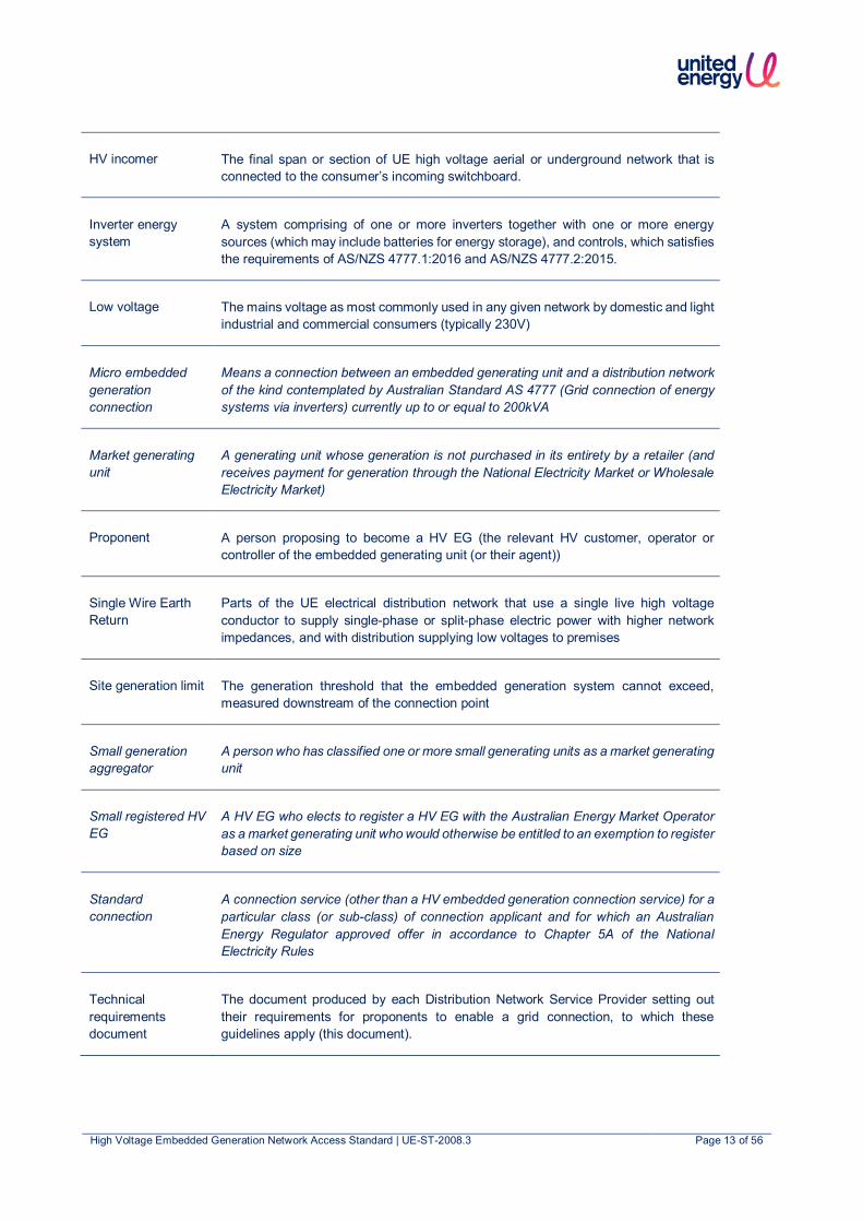
HV incomer The final span or section of UE high voltage aerial or underground network that is connected to the consumer’s incoming switchboard.
Inverter energy system
A system comprising of one or more inverters together with one or more energy sources (which may include batteries for energy storage), and controls, which satisfies the requirements of AS/NZS 4777.1:2016 and AS/NZS 4777.2:2015.
Low voltage The mains voltage as most commonly used in any given network by domestic and light industrial and commercial consumers (typically 230V)
Micro embedded generation connection
Means a connection between an embedded generating unit and a distribution network of the kind contemplated by Australian Standard AS 4777 (Grid connection of energy systems via inverters) currently up to or equal to 200kVA
Market generating unit
A generating unit whose generation is not purchased in its entirety by a retailer (and receives payment for generation through the National Electricity Market or Wholesale Electricity Market)
Proponent A person proposing to become a HV EG (the relevant HV customer, operator or controller of the embedded generating unit (or their agent))
Single Wire Earth Return
Parts of the UE electrical distribution network that use a single live high voltage conductor to supply single-phase or split-phase electric power with higher network impedances, and with distribution supplying low voltages to premises
Site generation limit The generation threshold that the embedded generation system cannot exceed, measured downstream of the connection point
Small generation aggregator
A person who has classified one or more small generating units as a market generating unit
Small registered HV EG
A HV EG who elects to register a HV EG with the Australian Energy Market Operator as a market generating unit who would otherwise be entitled to an exemption to register based on size
Standard connection
A connection service (other than a HV embedded generation connection service) for a particular class (or sub-class) of connection applicant and for which an Australian Energy Regulator approved offer in accordance to Chapter 5A of the National Electricity Rules
Technical requirements document
The document produced by each Distribution Network Service Provider setting out their requirements for proponents to enable a grid connection, to which these guidelines apply (this document).
High Voltage Embedded Generation Network Access Standard | UE-ST-2008.3 Page 14 of 56
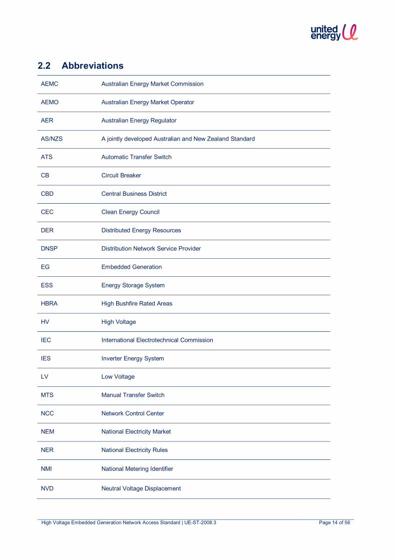
2.2 Abbreviations
AEMC Australian Energy Market Commission
AEMO Australian Energy Market Operator
AER Australian Energy Regulator
AS/NZS A jointly developed Australian and New Zealand Standard
ATS Automatic Transfer Switch
CB Circuit Breaker
CBD Central Business District
CEC Clean Energy Council
DER Distributed Energy Resources
DNSP Distribution Network Service Provider
EG Embedded Generation
ESS Energy Storage System
HBRA High Bushfire Rated Areas
HV High Voltage
IEC International Electrotechnical Commission
IES Inverter Energy System
LV Low Voltage
MTS Manual Transfer Switch
NCC Network Control Center
NEM National Electricity Market
NER National Electricity Rules
NMI National Metering Identifier
NVD Neutral Voltage Displacement

High Voltage Embedded Generation Network Access Standard | UE-ST-2008.3 Page 15 of 56
POC Point of Connection
REFCL Rapid Earth Fault Current Limiter
ROCOF Rate of Change of Frequency
SCADA Supervisory Control And Data Acquisition
SWER Single Wire Earth Return
TFB Total Fire Ban

High Voltage Embedded Generation Network Access Standard | UE-ST-2008.3 Page 16 of 56
2.3 Terminology The following terminology has been used in this document:
• The word “shall” indicates a mandatory requirement to comply with this document
• The word “may” indicates a recommendation that will not be mandatorily imposed on the proponent
• The word “should” indicates a requirement that may be mandatorily imposed on the proponent based on connection specific safety or operational requirements
2.3.1 Subcategories This document applies to all the following subcategories of HV EG connections unless otherwise specified:
1. HV EG IES capacity > 30 kVA – Any HV EG system, that is not a LV EG system, with total system capacity as set out in Table 1 for three phase network connection, meeting all relevant technical requirements for HV EG connections set out in this technical requirement document. Further subcategorised by:
a. Exporting
b. Non-exporting
2. HV non-IES EG connection – Any HV EG system that is not an IES, with a total system capacity as set out in Table 2 for three phase network connections, meeting all relevant technical requirements for HV EG connections set out in this technical requirement document. Further subcategorised by:
a. Exporting
b. Non-exporting
Where:
1. Exporting systems shall be considered to be HV EG systems operating in parallel with the HV distribution network and exporting electricity either via partial-export or full-export into the HV distribution network, where:
a. Partial-export HV EG systems limit the amount of export into the HV distribution network to an agreed export threshold defined in the connection agreement
b. Full-export HV EG systems can export into the HV distribution network to the full HV EG nameplate capacity (full AC rating).
2. Non-exporting systems shall be considered to be HV EG systems operating in parallel with the HV distribution network that are not approved to and limited to ensure they cannot export electricity into the HV distribution network.

High Voltage Embedded Generation Network Access Standard | UE-ST-2008.3 Page 17 of 56
3. Relevant Rules, Regulations, Standards and Codes
3.1 Standards and Codes This section lists the Australian and international standards and industry codes which shall apply to the design, manufacture, installation, testing and commissioning, and operation and maintenance of all plant and equipment for HV EG connections to the UE HV distribution network. The latest version of the Australian and international standards and industry codes shall be used.
In the event of any inconsistency between Australian and international standards and industry codes and UE’s technical requirements, UE technical requirements shall prevail.
Table 3: Applicable Standards and Codes
Standard Title AS 2067 Substations and high voltage installations exceeding 1kV a.c. AS/NZS 3000 Electrical installations (known as the Australian/ New Zealand Wiring Rules) AS/NZS 3010 Electrical installations – Generating Sets AS/NZS 3011 Electrical installations – Secondary batteries installed in buildings AS/NZS 4777 Grid connection of energy systems via inverters (multiple parts) AS/NZS 5033 Installation and safety requirements for photovoltaic (PV) arrays AS/NZS 5139 Electrical installation – Safety of battery systems for use with power conversion equipment AS 60034 Rotating electrical machines AS/NZS 60479 Effects of current on human beings and livestock SA/SNZ TR IEC 61000
Electromagnetic compatibility (EMC)
IEC 62116 Utility-interconnected photovoltaic inverters – Test procedure of islanding prevention measures
IEEE Standard 1547 IEEE Standard for Interconnecting Distributed Resources with Electric Power Systems AS/NZS 1026 Electric Cables – Impregnated Paper Insulated – For Working Voltages up to and including
19/33 (36) kV AS/NZS 1429.1 Electric Cables – Polymeric Insulated – For Working Voltages 1.9/3.3 (3.6) kV up to and
including 19/33 (36) kV AS/NZS 61000 series Electromagnetic Compatibility AS 60044 Instrument Transformers AS/NZS 60076 Power Transformers AS/NZS 60898 Electrical accessories – Circuit Breakers for overcurrent protection for household and similar
installations AS/NZS IEC 60947 Low-voltage switchgear and control gear IEC 60255 Measuring relays and protection equipment IEC 62271 High voltage switchgear and controlgear UL 508 Standard for Industrial Control Equipment

High Voltage Embedded Generation Network Access Standard | UE-ST-2008.3 Page 18 of 56
3.2 Legislation and Regulation This section lists all the relevant legislation and regulations which shall apply to the design, manufacture, installation, testing and commissioning, and operations and maintenance of all plant and equipment for HV EG connections to the distribution network. The latest version of the legislation and regulations shall be applicable.
In the event of any inconsistency between legislation and regulations and UE’s technical requirements, the legislation and regulation shall prevail.
Table 4: Applicable Legislation and Regulations
Document Title Description National Electricity Rules Chapter 5 Network Connection, Planning and Expansion National Electricity Rules Chapter 5A Electricity Connection for Retail Customers Electricity Distribution Code1 Regulates the distribution of electricity, connections to distribution
networks, and the transfer of electricity between distribution systems so that they are undertaken in a safe, efficient, and reliable manner
Electricity Industry Guideline 15 - Connection of Embedded Generation
Provides arrangements for connecting embedded generating units to distribution systems
Victorian Service and Installation Rules1 Provides industry agreed technical requirements that meet all legislative and code requirements for the supply and metering related aspects of any connection to the Victorian electricity supply networks.
Electrical Safety (Installation) Regulations Provides details on regulatory obligations for electricity installation works in Victoria
Note:
1. Where the HV EG system is installed in areas with rapid earth fault current limiter (REFCL) deployment, the HV EG system shall also comply with the REFCL related requirements stipulated in the Electricity Distribution Code and Victorian Service and Installation Rules. REFCLs are currently installed in UE’s Frankston South, Dromana and Mornington substations. Proponents shall confirm with UE the applicability of REFCL related requirements to the HV EG system.
4. Fees and Charges Refer to UE’s website2 for type of connection fees applicable to HV EG connections and how these fees are determined. Where network augmentation works are required to accommodate the HV EG connection, a separate quote will be provided to the proponent. This is in addition to the application fees and charges.
2 https://www.unitedenergy.com.au/industry/solar-energy/negotiated

High Voltage Embedded Generation Network Access Standard | UE-ST-2008.3 Page 19 of 56
Part A – IES Requirements

High Voltage Embedded Generation Network Access Standard | UE-ST-2008.3 Page 20 of 56
5. Technical Requirements for HV EG IES This section details the technical requirements for HV EG IES connections.
5.1 Labelling and Signage The labels and signs on the installation, including cables, shall be as per AS 2067, AS/NZS 4777.1, AS/NZS 3000 and AS/NZS 5033. If the EG output is at LV and connects to the UE HV network, relevant labelling shall be as per Energy Safe Victoria (ESV) application requirements of AS/NZS 5033, AS/NZS 3000 and any other relevant regulatory requirements.
Site specific labelling for additional energy sources and operating procedure for the energy sources shall be installed at each isolation point that has a possibility of energy feedback from the IES.
5.2 Maximum System Capacity Refer to Table 1 for details of maximum system capacity.
5.3 Generation Control
5.3.1 Export Limits at Connection Point The maximum export limit of HV EG IES connections is as per Table 1.
The export limit where required will be negotiated with the proponent as part of the application process. The export limit imposed may be a “hard” or “soft” limit, consistent with the definitions within AS4777.1.
The ability of the proponent’s HV EG system to export at the export limit is not guaranteed, but rather, it will depend upon network characteristics which change over time. UE reserves the right to revise the export limit of the proponent’s HV EG system if the system adversely affects the network safety and/or performance.
5.3.2 Anti-Islanding Considerations • IES systems with total capacity ≥ 30kVA but < 1,000kVA - To ensure unintentional island does not form following
an electricity distribution network outage, anti-islanding protection functions and neutral voltage displacement shall be implemented. Refer to Table 6 and Table 9 for detailed protection requirements.
• IES systems with total capacity ≥ 1,000kVA - To ensure an unintentional island does not form following an electricity distribution network outage, IES systems will require reliable and immediate disconnection from the network. Remote trip schemes are considered to be reliable and robust and this is UE’s preferred option for large IES systems. Alternative schemes may be considered on a case-by-case basis. However, for these alternative schemes, operation restrictions may apply and UE will not be able to guarantee the perpetuity of such schemes due to network changes over time. Refer to Section 5.7.2.2 for remote trip scheme requirements.
5.3.3 Network Asset Constraints Considerations Introduction of HV IES EG may result in the limits of network assets being exceeded (e.g. thermal limits, reverse power flow, fault current contribution, protection grading issues, protection grading with adjacent feeder faults, etc.) and hence, require network augmentation. If the proponent does not wish to pay for the network augmentation, an export limit may be imposed as an alternative.
5.3.4 Site Generation Limit Downstream of Connection Point The Victorian Service and Installation Rules stipulated that HV EG electrical characteristics shall be compatible with the relevant distributor’s network, in this case UE’s distribution network. The HV EG output shall not exceed the capability (e.g. thermal limits, harmonics etc.) of the network assets at, or upstream of the network connection point.

High Voltage Embedded Generation Network Access Standard | UE-ST-2008.3 Page 21 of 56
5.4 Inverter Energy System The IES shall comply with the following requirements:
1. type tested and certified as being compliant with an accreditation number or certificate of suitability as evidence of compliance to IEC 62116 for anti-islanding protection
2. IES EG units should comprise of inverters that have the following inverter power quality response modes available:
a. Reactive power control mode
b. Central control mode via a master/slave system
c. Volt response modes (i.e. volt-var and volt-watt)
d. Fixed power factor or reactive power mode
e. Power rate limit (i.e. ramp rate control)
5.5 Network Connection and Isolation Network connection and isolation requirements shall be as per the following:
• Complies with the Electricity Distribution Code
• Complies with the Victorian Service and Installation Rules 2014 (A2)
• Protection and control system of the installation at POC and downstream of the POC as agreed with UE
• Operation, ownership and responsibility for protection and control schemes downstream of the POC shall lie with the customer and the generator nominated in the Distribution Connection EG agreement
All assets upstream of the POC in UE’s distribution network are owned and operated by UE.
5.6 Earthing The earthing requirements shall be:
1. For installations with IES operating at greater than 1kV a.c., earthing requirements shall comply with AS 2067, AS/NZS 60479.1 and AS/NZS 3000.
2. For ESS, additional requirements shall be as per AS/NZS 5139 and AS 3011.2.
High Voltage Embedded Generation Network Access Standard | UE-ST-2008.3 Page 22 of 56
5.7 Protection
5.7.1 Protection Requirements at HV Point of Connection (POC) As per the Victorian SIR, the proponent is required to have the following protection at their POC:
• Overcurrent
• Earth Fault
• Sensitive Earth Fault
The purpose of this protection is to ensure that any faults within the customer’s premises will be cleared via operation of this protection.
These protection settings shall be site specific. Examples of site specific factors include circuit rating, loading, fault level, device grading etc. Operation of overcurrent/earth fault protection shall immediately trip a suitably fault rated circuit breaker. Self-powered relays are not permitted.
The fault clearance time for a solid phase-to-phase or phase-to-ground short circuit at the network connection point must be less than 150ms. Where this fault clearance time cannot be achieved, the proponent should consult with UE to determine the maximum permissible fault clearance time to be adopted.
It is necessary to undertake a grading study and to grade with the upstream network protection. If the immediate upstream network protection device is a circuit breaker, the minimum grading margin shall be 0.3s.
5.7.2 IES Protection The intention of this section is to ensure the safe and reliable operation of the distribution network for operating personnel, proponents, customer (i.e. electricity consumers) and the general public. The HV EG IES intending to connect to the network shall not adversely affect the operation and safety of other existing network users. UE may impose limitations and/or conditions of operation on the new HV EG IES connection in order to mitigate these issues.
Table 5: HV EG IES Protection Requirements
IES protection Three Phase Connection
Inverter integrated protection according to AS/NZS 4777.2 Yes
IES Backup Protection Yes
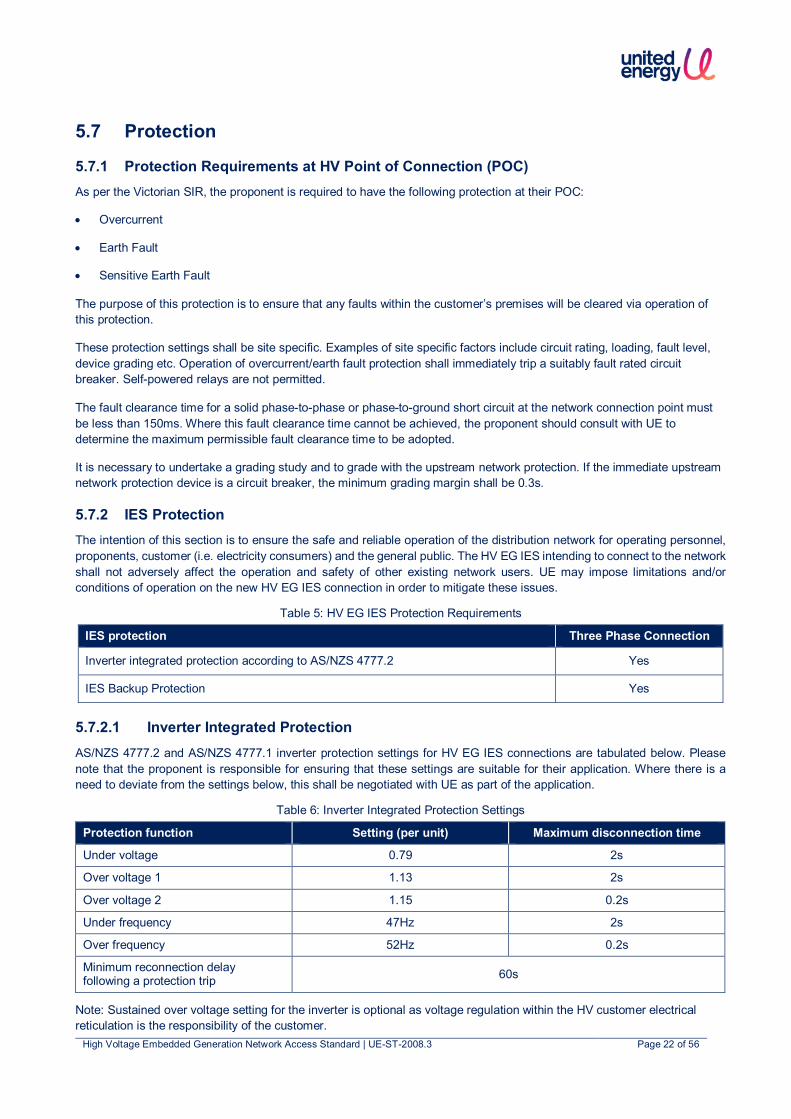
5.7.2.1 Inverter Integrated Protection AS/NZS 4777.2 and AS/NZS 4777.1 inverter protection settings for HV EG IES connections are tabulated below. Please note that the proponent is responsible for ensuring that these settings are suitable for their application. Where there is a need to deviate from the settings below, this shall be negotiated with UE as part of the application.
Table 6: Inverter Integrated Protection Settings
Protection function Setting (per unit) Maximum disconnection time
Under voltage 0.79 2s
Over voltage 1 1.13 2s
Over voltage 2 1.15 0.2s
Under frequency 47Hz 2s
Over frequency 52Hz 0.2s
Minimum reconnection delay following a protection trip 60s
Note: Sustained over voltage setting for the inverter is optional as voltage regulation within the HV customer electrical reticulation is the responsibility of the customer.

High Voltage Embedded Generation Network Access Standard | UE-ST-2008.3 Page 23 of 56
5.7.2.2 IES Backup Protection Backup protection requirements shall apply to HV EG IES connections as per Table 5. The protection functions for each HV EG IES connection subcategory is shown in Table 7. The protection relay shall be compliant with IEC 60255.
Table 7: Backup protection requirements
Protection function Exporting to UE Network1
Non-exporting to UE Network1,2
Network reverse power protection ‒
Phase balance protection • Current unbalance protection • Voltage unbalance protection
‒
Passive anti-islanding protection
Reconnection Time Delay
Remote tripping ‒ ‒
Synchronisation check (for EG systems configured to operate in island mode when disconnected from UE network)
Symbols are used to denote protection requirements, where:
Represents that the protection shall be required
‒ Represents that the protection may be required
Represents that the protection shall not be required
Notes:
1. For customers exporting to the HV reticulation, the voltage and current sensing devices of the protection relay are to be located at HV and upstream of all IES. The protection relay shall be capable of disconnecting the contribution from all IES when a fault is detected.
2. For customers who are exporting only to their LV reticulation, the voltage and current sensing devices of the protection relay are to be located at LV and upstream of all IES. The protection relay shall be capable of disconnecting the contribution from all IES when a fault is detected.
The protection schemes shall be designed such that:
• All protection elements initiate tripping of a suitably rated circuit breaker (tripping of CB isolates the IES); or
• Current based protection elements (e.g. overcurrent, earth fault) shall initiate tripping of a suitably rated circuit breaker while voltage based protection elements (e.g. over voltage, under voltage, over frequency, under frequency) may initiate opening of a suitably rated contactor.
• The protection scheme shall be fail-safe such that in the event of any component failure (e.g. device fault, loss of auxiliary supply, etc.), the HV EG IES shall be automatically disconnected from the network within 2s.
For voltage-based protection elements, if the trip/open signal is not hard wired to the disconnection device (i.e. circuit breaker or contactor), a dedicated wireless trip scheme may be used. The trip/open signal shall be initiated by a protection grade device (IEC 60255 compliant). The wireless trip scheme shall incorporate control equipment (i.e. devices that utilise digital input and output functions) compliant to AS/NZS IEC 60947 or equivalent. The communication used shall be compliant with internationally recognised standards (e.g. IEC, AS/NZS or IEEE).
The receipt of the trip/open signal shall operate the disconnection device directly. This is illustrated in Figure 1 below:
High Voltage Embedded Generation Network Access Standard | UE-ST-2008.3 Page 24 of 56
IEC 60255 Compliant
Protection Device
AS/NZS IEC 60947Control
Equipment
Trip/Open signal
Trip/Open Signal
Digi
tal O
utpu
t
Digi
tal I
nput
Wireless Transmitter
HV EG Circuit Breaker / Contactor
AS/NZS IEC 60947Control
Equipment
Digi
tal O
utpu
t
Wireless Receiver
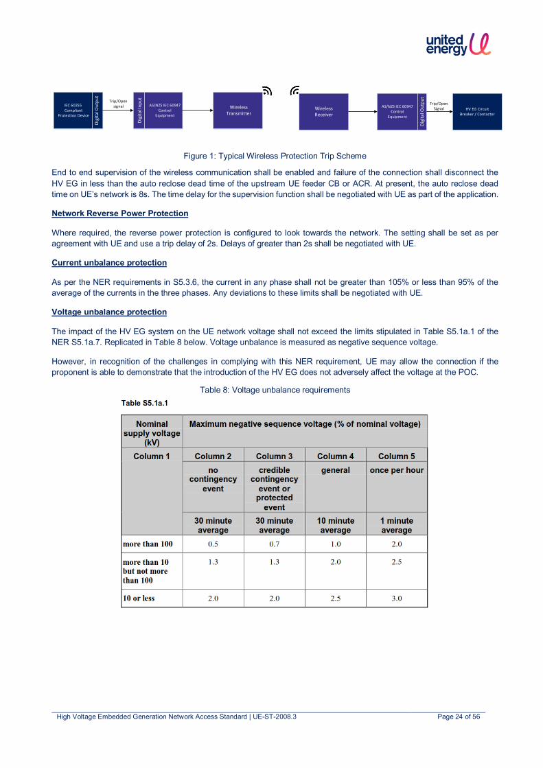
Figure 1: Typical Wireless Protection Trip Scheme
End to end supervision of the wireless communication shall be enabled and failure of the connection shall disconnect the HV EG in less than the auto reclose dead time of the upstream UE feeder CB or ACR. At present, the auto reclose dead time on UE’s network is 8s. The time delay for the supervision function shall be negotiated with UE as part of the application.
Network Reverse Power Protection
Where required, the reverse power protection is configured to look towards the network. The setting shall be set as per agreement with UE and use a trip delay of 2s. Delays of greater than 2s shall be negotiated with UE.
Current unbalance protection
As per the NER requirements in S5.3.6, the current in any phase shall not be greater than 105% or less than 95% of the average of the currents in the three phases. Any deviations to these limits shall be negotiated with UE.
Voltage unbalance protection
The impact of the HV EG system on the UE network voltage shall not exceed the limits stipulated in Table S5.1a.1 of the NER S5.1a.7. Replicated in Table 8 below. Voltage unbalance is measured as negative sequence voltage.
However, in recognition of the challenges in complying with this NER requirement, UE may allow the connection if the proponent is able to demonstrate that the introduction of the HV EG does not adversely affect the voltage at the POC.
Table 8: Voltage unbalance requirements
High Voltage Embedded Generation Network Access Standard | UE-ST-2008.3 Page 25 of 56
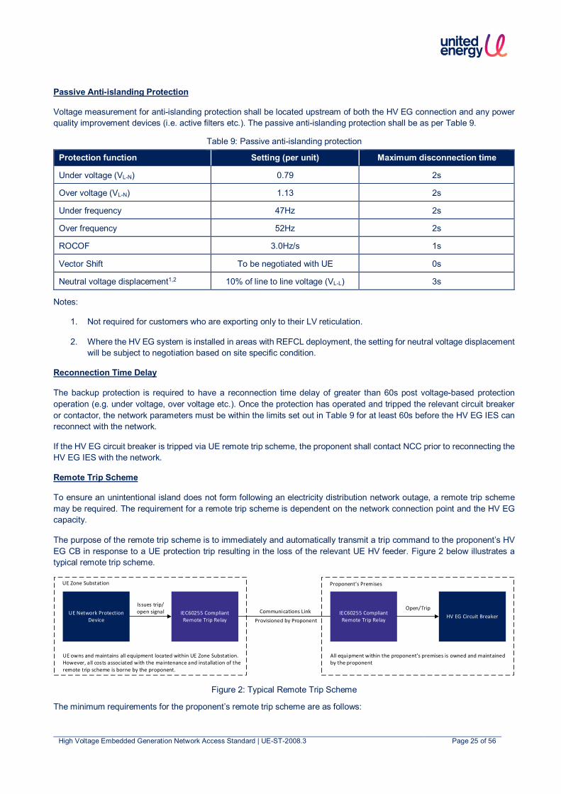
Passive Anti-islanding Protection
Voltage measurement for anti-islanding protection shall be located upstream of both the HV EG connection and any power quality improvement devices (i.e. active filters etc.). The passive anti-islanding protection shall be as per Table 9.
Table 9: Passive anti-islanding protection
Protection function Setting (per unit) Maximum disconnection time
Under voltage (VL-N) 0.79 2s
Over voltage (VL-N) 1.13 2s
Under frequency 47Hz 2s
Over frequency 52Hz 2s
ROCOF 3.0Hz/s 1s
Vector Shift To be negotiated with UE 0s
Neutral voltage displacement1,2 10% of line to line voltage (VL-L) 3s
Notes:
1. Not required for customers who are exporting only to their LV reticulation.
2. Where the HV EG system is installed in areas with REFCL deployment, the setting for neutral voltage displacement will be subject to negotiation based on site specific condition.
Reconnection Time Delay
The backup protection is required to have a reconnection time delay of greater than 60s post voltage-based protection operation (e.g. under voltage, over voltage etc.). Once the protection has operated and tripped the relevant circuit breaker or contactor, the network parameters must be within the limits set out in Table 9 for at least 60s before the HV EG IES can reconnect with the network.
If the HV EG circuit breaker is tripped via UE remote trip scheme, the proponent shall contact NCC prior to reconnecting the HV EG IES with the network.
Remote Trip Scheme
To ensure an unintentional island does not form following an electricity distribution network outage, a remote trip scheme may be required. The requirement for a remote trip scheme is dependent on the network connection point and the HV EG capacity.
The purpose of the remote trip scheme is to immediately and automatically transmit a trip command to the proponent’s HV EG CB in response to a UE protection trip resulting in the loss of the relevant UE HV feeder. Figure 2 below illustrates a typical remote trip scheme.
Figure 2: Typical Remote Trip Scheme
The minimum requirements for the proponent’s remote trip scheme are as follows:
UE Network Protection Device
IEC60255 Compliant Remote Trip Relay
Issues trip/open signal IEC60255 Compliant
Remote Trip Relay HV EG Circuit BreakerOpen/Trip
UE Zone Substation Proponent’s Premises
Communications Link
Provisioned by Proponent
All equipment within the proponent’s premises is owned and maintained by the proponent
UE owns and maintains all equipment located within UE Zone Substation. However, all costs associated with the maintenance and installation of the remote trip scheme is borne by the proponent.

High Voltage Embedded Generation Network Access Standard | UE-ST-2008.3 Page 26 of 56
• Backup protection (including voltage and current sensors) that forms part of the customer HV protection scheme shall be installed at the HV incomer of the installation. Any changes to the location of the backup protection, including voltage and current sensors, shall be negotiated with UE.
• Send a remote trip signal to the proponent’s HV EG CB for any relevant UE protection operation, “loss of mains” network scenarios on the HV supply feeder including overcurrent, earth fault and sensitive earth fault protection.
• UE Network Control Centre (NCC) operators shall have the facility to trip the proponent’s HV EG CB via UE NCC SCADA. This trip shall be latched until NCC resets the trip signal. This trip signal shall result in the proponent’s HV EG CB closing to be blocked as well.
• Send a remote trip signal to the proponent’s HV EG CB for any manual initiated open command on the UE HV supply feeder/ACR (both via UE operator on site at the supply zone substation or controller in the UE NCC).
• Tripping of the proponent’s HV EG CB shall be completed within a maximum of 200ms from the time of the UE protection operation or manually initiated command. Any deviation of the disconnection time shall be negotiated with UE.
• The scheme shall be configured so that the proponent’s HV EG CB is automatically tripped in the event the integrity of the scheme is compromised, including equipment failure associated with the scheme. The proponent’s HV EG CB shall trip if the integrity of the scheme is not restored (e.g. equipment failure, loss of auxiliary supply) within 2s to ensure the scheme is fail safe.
• End to end supervision of the communication shall be enabled and failure of the connection shall disconnect the HV EG in less than the auto reclose dead time of the upstream UE isolation device. The time delay for the supervision function shall be negotiated with UE.
• At a minimum the following information shall be telemetered to the UE NCC via SCADA for each proponent’s remote trip scheme:
o Equipment fail alarm for both ends
o Health of communications link
o Remote trip received by proponent
o Proponent HV EG CB fail to open (after receipt of remote trip signal)
o Proponent HV EG CB status (open/closed)
o Loss of mains (loss of network) protection operated
o Proponent generation (kW) with measurement accuracy within ±2%
o Proponent reactive power output (kvar) with measurement accuracy within ±2%
o Proponent net load (kW) with measurement accuracy within ±2%
o Proponent net reactive power consumption (kvar) with measurement accuracy within ±2%
o Additional voltage, current or power quality parameters such as harmonics, flicker, voltage dips and swells may be required. These will be negotiated as part of the application process.
5.7.3 Special Operational Conditions The following HV EG protection is required for special UE network operational conditions:
• Live line work by UE
When works are undertaken near or on live HV distribution feeders, UE enables a live line operating mode which disables automatic reclose and enables low set instantaneous overcurrent and earth fault protection. With live line mode enabled, grading may be compromised with downstream protection (including the protection associated with the HV EG installation). If the proponent wishes to operate their HV EG when live line mode is enabled, the HV EG

High Voltage Embedded Generation Network Access Standard | UE-ST-2008.3 Page 27 of 56
protection will also need to act much more quickly to disconnect from the network for phase-phase faults on the HV feeder while live line sequence is enabled. As such, additional requirements may be required and shall be negotiated with UE as part of the application.
• Total Fire Ban (TFB) Days
For HV EG installed in HBRA may experience TFB restrictions, if the proponent chooses to operate their HV EG on TFB days, the HV EG will be required to disconnect instantaneously to avoid contribution to a fault. As such, additional requirements may be required and shall be negotiated with UE as part of the application.
5.7.4 Switchgear and control gear requirements The switchgear and control gear associated with the HV EG IES connection shall be:
• Compliant to all relevant standards, codes legislations and regulations listed in Section 3.
• Switchgear – appropriate breaking and thermal capacities based on the fault level at the switchgear location. Refer to Figure 3 below (this is extracted from Table 5 of the Electricity Distribution Code) for the maximum HV fault level. Site specific fault level at HV customer POC can be obtained from UE.
Figure 3: Fault levels extracted from the Electricity Distribution Code3
• EG isolation – All EG shall have a lockable isolating device owned and operable by the proponent.
5.7.5 Interlocking For cases where a HV non-IES EG exists downstream of the same point of connection as a HV EG IES, a break before make interlocking system shall be installed if no other control systems are in place. This is to ensure the safe parallel operation of the HV EG IES and the HV non-IES EG. Where the following are implemented:
• Automatic transfer switch (ATS)
The HV EG IES system shall be disconnected prior to the switching of the ATS. This interlocking system shall be fail safe.
• Manual transfer switch (MTS)
Installations of manual transfer switches shall include suitable warning label instructions for the HV EG IES to be disconnected prior to the switching of the transfer switch.
• When connecting an islanded HV EG system to the network, synchronisation check protection shall be implemented.
5.8 Operating Voltage and Frequency UE has an obligation to maintain the network voltage in compliance to the Distribution Code. Introduction of HV EG IES to the network may impact the network voltage and deviate it beyond the limits of the Distribution Code. The EG shall not adversely affect the voltage at the point of connection (POC) such that the voltage deviates beyond the limits of the Electricity Distribution Code.
3 https://www.esc.vic.gov.au/electricity-and-gas/codes-guidelines-and-policies/electricity-distribution-code

High Voltage Embedded Generation Network Access Standard | UE-ST-2008.3 Page 28 of 56
The HV EG system should operate at the frequency ranges in compliance with AEMC’s Frequency Operating Standard. Where the HV EG system are unable to operate within the AEMC Frequency Operating Standard, this shall be negotiated with UE.
It is the responsibility of the proponent to maintain the voltage of the HV and LV electrical reticulation within the proponent’s premises.
5.9 Metering Metering shall be installed as per Victorian Service and Installation Rules4.
5.10 Power Quality HV EG IES shall comply with the applicable power quality requirements of the AS/NZS 61000 series as well as relevant Victorian regulations and licence conditions, including but not limited to:
• Network voltage control • Voltage fluctuations • Harmonics • Voltage balance
5.10.1 IES Volt Response Modes IES may be equipped with power quality response modes to either maintain the power quality at its point of connection or provide support to the network. Site specific requirements are to be negotiated with UE during the technical assessment. This encompasses the use of inverter volt response modes, power factor control modes, etc.
5.10.2 Network Ancillary Services AEMO is responsible for maintaining the network frequency close to 50Hz in accordance with the NEM frequency standards and for keeping the voltage within an acceptable range at particular nodes on the transmission network and for scheduling power flow between regions while maintaining power flows within the capability of plant. AEMO achieves these objectives by dispatching scheduled generation to match the load and via ancillary services.
Ancillary services can be one of the following:
• Frequency Control Ancillary Services (FCAS)
• Network Control Ancillary Services (NCAS)
In practice FCAS and NCAS are offered by HV EGs by providing either real power or reactive power reserves that may be required in response to a network fluctuation, disturbance or event or based on load flows to provide local network support. Any HV EG has the option to provide ancillary services.
HV EG participating in network ancillary services (potentially IES with ESS) has the potential to rapidly change network load, resulting in significant voltage impact on the local network. Hence, the HV EG shall adopt necessary controls to prevent adverse impacts on the power quality at the point of connection while generating to provide ancillary services.
5.11 HV Embedded Network It is the responsibility of the proponent to maintain the voltage of the HV and LV electrical reticulation within the proponent premises as per the Electricity Distribution Code. The proponent is also responsible for the operation of the EG system downstream of the HV POC.
5.12 Communications Requirements for Monitoring Systems For HV EG IES systems requiring remote trip schemes, the communication requirements are outlined in Section 5.7.2.2.
4 http://www.victoriansir.org.au/

High Voltage Embedded Generation Network Access Standard | UE-ST-2008.3 Page 29 of 56
Communication requirements for alternate control schemes as mentioned in Section 5.3.2 shall be negotiated with UE as part of the application process.
For all other HV EG IES systems, UE does not require the proponent to provide any remote monitoring data to UE. However, proponents shall install remote monitoring of their HV EG IES systems to ensure that the proponent is promptly notified of issues on their HV EG IES systems. Remote monitoring of HV EG IES systems by the proponent may be achieved via use of IES manufacturer’s software applications.
5.13 Data and Information
5.13.1 Static Data and Information The static data and information shall be provided by the proponent to UE as listed in Appendix D: Static Data and Information. UE will provide this data to AEMO’s Distributed Energy Resource Register (DERR) on behalf of the proponent.
5.13.2 Dynamic Data and Information For HV EG IES systems requiring remote trip schemes, the dynamic data requirements are outlined in Section 5.7.2.2. Dynamic data requirements for HV EG IES systems implementing alternate control schemes as mentioned in Section 5.3.2. Shall be negotiated with UE as part of the application process.
5.14 Cybersecurity All devices and equipment settings associated with the HV EG system shall be secured against inadvertent or unauthorised tampering. Changes to the HV EG settings shall require the use of tools (e.g. special interface devices and passwords) and special instructions which shall not be provided to unauthorised personnel.
5.15 Technical Studies Technical studies shall be completed as part of the connection application as per Table 10.
Table 10: Technical Studies Required for HV EG IES Connections
Technical Studies HV EG IES
Power Flow Study ‒
Fault Level Contribution Study
Protection Study
Power Quality Impact Study (including harmonics, flicker, voltage step change, unbalance)
‒
Earthing Study ‒
Dynamic System Studies (see Section 5.15.5) ‒
Symbols are used to denote technical studies requirements, where:
Represents that technical studies shall be required ‒ Represents that technical studies may be required
As part of the application process, UE shall provide the following network data to enable the proponent to complete the required technical studies:
• network fault levels up to the point of common coupling
• network model
• network protection information for UE assets (e.g. protection settings)
• network equipment information for UE assets (e.g. line and conductor ratings)
High Voltage Embedded Generation Network Access Standard | UE-ST-2008.3 Page 30 of 56
Where one or more of the technical studies does not meet the assessment criteria, UE shall provide the proponent feedback on components of the submission that require further work. The proponent has the option to discuss with UE:
• Alternative configurations of the HV EG IES systems
• Network augmentation (and associated cost of network augmentation)
5.15.1 Power Flow Study The requirement for a power flow study shall be negotiated with UE as part of the application process. Typically this is required for larger installations where there may be thermal impacts to UE’s distribution network or where there are impacts on the proponent’s maximum demand.
5.15.2 Power Quality Impact Studies The requirement for this study shall be negotiated with UE as part of the application process.
5.15.3 Fault Level Contribution Study and Protection Settings Report A comprehensive protection study is required for all HV EG installations. The fault level contribution and protection settings shall be included in this study.
Please refer to UE-FM-5001 EG Application Form (Non-Registered) for additional information. This form can be found on UE’s website.
5.15.4 Earthing Study An earthing study is required if alterations or additions are made to the proponent’s HV network.
5.15.5 System studies Steady state study
The following steady state studies may be required for HV EG applications:
• Power Flow Study (including network contingency analysis where applicable)
• Fault Level Contribution Study (including network contingency analysis where applicable)
• Protection Study (including network contingency analysis where applicable)
• Power Quality Impact Study (including harmonics, flicker, voltage step change, unbalance, network contingency analysis where applicable)
The proponent shall negotiate with UE to determine the required steady state studies for their application,
Dynamic study
Dynamic studies may be required depending on the following:
• outcome of steady state studies,
• presence of non-standard design features as part of the HV EG connection (e.g. STATCOM)
• location of the HV EG on the network
The studies may include:
• Transient/step frequency disturbance
• Transient/step voltage fluctuation
• Generator stability
High Voltage Embedded Generation Network Access Standard | UE-ST-2008.3 Page 31 of 56
• Generator governor control/excitation control
• Frequency response
• Fault ride through
The dynamic study requirements shall be negotiated with UE as part of the application process.

High Voltage Embedded Generation Network Access Standard | UE-ST-2008.3 Page 32 of 56
6. Testing and Commissioning for HV EG IES Testing and commissioning of the HV EG IES installation shall be undertaken by the proponent in accordance with AS 2067, AS/NZS 3000 and AS/NZS 5033, the CEC approved test regime (if applicable), and the equipment manufacturer’s specifications and to the technical requirements stipulated in this document. The testing and commissioning results shall demonstrate that the installed HV EG IES system meets the requirements of the connection agreement.
Note these tests shall be installation tests and not type tests of the equipment. Equipment type tests shall be as per IEC 62116 for inverters.
In addition, the following requirements for network connection of HV EG IES systems shall be met:
1. Testing and commissioning plan shall be produced by the proponent covering all newly installed equipment, interfaces with existing equipment and end to end testing of remote trip scheme (if installed). The plan shall be produced based on the sequence of testing on site.
2. All tests shall be provided in a test report format or ITP format with reference made to the commissioning plan. The test report shall clearly indicate pass/fail criteria for each test.
3. Pre-commissioning shall be undertaken to prove the functionality of the complete scheme.
4. The results of all testing and commissioning activities shall be thoroughly documented and shall align with the commissioning plan.
5. Testing and commissioning acceptance shall be signed off by a suitably qualified and authorised person.
6. Testing and commissioning acceptance may require UE to carry out witnessing at the proponent’s expense.
Table 11: Testing and Commissioning Requirements for HV EG IES Connections
Testing and commissioning submission HV EG IES
Exporting Non-exporting
Protection settings and performance1 ≤
HV switchgear integrity and performance ≤
CTs and VTs performance test results ≤
Power quality settings and performance ‒ ‒
Export limits settings and performance ‒
Earth grid in compliance to AS 2067:2016 ‒ ‒
Communications performance for monitoring system2
Site Maintenance Procedure ≤ ≤
Safety and Operating Procedure ≤ ≤
Confirm system is as per specifications ≤ ≤
Confirm single line diagram is located on site ≤ ≤
As-built documentation and drawings ≤ ≤
Certificate of Electrical Safety (CES) ≤ ≤
UE HV EG Commissioning forms (see Appendix D) ≤ ≤
Symbols are used to denote testing and commissioning requirements, where:
Represents that testing and commissioning shall be required
‒ Represents that testing and commissioning may be required

High Voltage Embedded Generation Network Access Standard | UE-ST-2008.3 Page 33 of 56
Notes:
1. Protection Settings and Performance
• The HV EG IES protection relay shall be tested by secondary injection. All necessary functional tests shall be carried out to prove that the protection and control schemes operate as per the design.
2. Communications schemes for monitoring
• End to end testing of monitoring data points are required.
• Where remote tripping is required, full end-to-end testing of the remote trip scheme is required.

High Voltage Embedded Generation Network Access Standard | UE-ST-2008.3 Page 34 of 56
7. Operations and Maintenance The operation and maintenance requirements for HV EG IES connections to the UE network, includes:
1. The HV EG IES system shall be operated and maintained by the proponent to ensure compliance with their connection agreement and all legislation, codes, and/or other regulatory instruments at all times
2. Confirmation that maintenance of the HV EG IES system has been completed shall be submitted to UE by the proponent at a specified interval as agreed with UE
The following documentation is to be kept at the HV EG IES installation in compliance with relevant codes and is to be readily accessible by UE’s representatives and other authorised parties:
• A single line diagram showing all electrical metering points, protection functions and zones of coverage.
• A record of all approved protection settings.
• A copy of the approved operating procedures.
• Maintenance plan and all subsequent maintenance records.
In addition, the proponent shall:
1. Maintain and operate the HV EG IES installation in a safe condition
2. Ensure that any changes to the HV EG IES installation are performed by an electrician lawfully permitted to do the work and that the proponent holds a Certificate of Electrical Safety (CES) issued in respect of any of the changes
3. Seek UE approval prior to altering the connection in terms of an addition, upgrade, extension, expansion, augmentation or any other kind of alteration, including any changes to firmware and protection functions or settings.
If any breach of this technical standard is suspected, UE may undertake an investigation. If the investigation reveals a breach, the proponent shall be required to rectify this breach and pay UE for the costs associated with the investigation and associated works undertaken by UE.

High Voltage Embedded Generation Network Access Standard | UE-ST-2008.3 Page 35 of 56
Part B – Non-IES requirements

High Voltage Embedded Generation Network Access Standard | UE-ST-2008.3 Page 36 of 56
8. Technical Requirements for HV non-IES EG This section details the technical requirements for HV non-IES EG connections.
8.1 Labelling and Signage The labels and signs on the installation, including cables, shall be as per AS 2067 and AS/NZS 3000. Site specific labelling for additional energy sources and operating procedure for the energy sources shall be installed at each isolation point that has a possibility of energy feedback from the HV non-IES EG.
8.2 Maximum System Capacity Refer to Table 2 for details of maximum system capacity.
8.3 Generation Control
8.3.1 Export Constraints at Connection Point The maximum export limit of HV non-IES EG connections is as per Table 2.
The export constraints where required will be negotiated with the proponent as part of the application process.
The ability of the proponent’s HV EG system to export at the export limit is not guaranteed, but rather, it will depend upon network characteristics which changes over time. UE reserves the right to revise the export limit of the proponent’s HV EG system if the system adversely affects the network safety and/or performance.
8.3.1.1 Anti-Islanding Considerations • HV non-IES EG systems with total capacity < 1,000kVA – To ensure an unintentional island does not form following
an electricity distribution network outage, HV non-IES EG shall incorporate anti-islanding protection functions such as ROCOF, vector shift, NVD etc. to reliably and automatically disconnect from the network. Refer to Table 14 and 16 for detailed protection requirements. If there is insufficient load on the network to implement a reliable ROCOF and vector shift setting, minimum import may be considered or alternatively remote trip scheme may be required.
• HV non-IES EG systems with total capacity ≥ 1,000kVA - To ensure an unintentional island does not form following an electricity distribution network outage, HV non-IES EG systems will require reliable and immediate disconnection from the network. Remote trip schemes are considered to be reliable and robust and this is UE’s preferred option for large HV non-IES EG systems. Alternatively, minimum import depending on the connection point will avoid the requirement for such schemes. Refer to Section 8.6.2.2 for remote trip scheme requirements.
8.3.1.2 Network Asset Constraints Considerations Introduction of HV non-IES EG may result in the limits of network assets being exceeded (e.g. thermal limits, reverse power flow, fault current contribution, protection grading issues, protection grading with adjacent feeder faults, etc.) and hence, require network augmentation. If the proponent does not wish to pay for the network augmentation, an export limit may be imposed as an alternative.
8.3.2 Site Generation Limit Downstream of Connection Point The Victorian Service and Installation Rules stipulated that HV EG electrical characteristics shall be compatible with the relevant distributor’s network, in this case UE’s network. The HV EG output shall not exceed the capability (e.g. thermal limits, harmonics etc.) of the network assets at, or upstream of the network connection point.

High Voltage Embedded Generation Network Access Standard | UE-ST-2008.3 Page 37 of 56
8.4 Network Connection and Isolation Network connection and isolation requirements shall be as per the following:
• Complies with the Electricity Distribution Code
• Complies with the Victorian Service and Installation Rules
• Protection and control system of the installation at POC and downstream of the POC as agreed with UE
• Operation, ownership and responsibility for protection and control schemes downstream of the POC shall lie with the proponent and the generator nominated in the Distribution Connection EG agreement
All assets upstream of the POC in UE network is owned and operated by UE.
8.5 Earthing For installations with non-IES operating at greater than 1kV a.c., earthing requirements shall comply with AS 2067, AS/NZS 60479.1 and AS/NZS 3000. The earthing system for the HV non-IES EG system must provide satisfactory earthing independent of UE’s earthing system.
8.6 Protection
8.6.1 Protection Requirements at HV Point of Connection (POC) As per the current Victorian SIR, the proponent is required to have the following protection at their POC:
• Overcurrent
• Earth Fault
• Sensitive Earth Fault
The purpose of this protection is to ensure that any faults within the customer’s premises will be cleared via operation of this protection.
These protection settings shall be site specific. Examples of site specific factors include circuit rating, loading, fault level, device grading etc. Operation of overcurrent/earth fault protection shall immediately trip a suitably fault rated circuit breaker. Self-powered relays are not permitted. Where possible, the protection trip output shall be latched.
The fault clearance time for a solid phase-to-phase or phase-to-ground short circuit at the network connection point must be less than 150ms. Where this fault clearance time cannot be achieved, the proponent should consult with UE to determine the maximum permissible fault clearance time to be adopted.
It is necessary to undertake a grading study and to grade with the upstream network protection. If the immediate upstream network protection device is a circuit breaker, the minimum grading margin shall be 0.3s.
8.6.2 HV non-IES EG Protection The intention of this section is to ensure the safe and reliable operation of UE’s network for operating personnel, proponents and the general public. The HV non-IES EG intending to connect to the network shall not adversely affect the operation and safety of other existing network users. UE may impose limitations and/or conditions of operation on the new HV non-IES EG connection in order to mitigate these issues.
Table 12: Protection requirements for HV non-IES EG
HV non-IES EG protection Three Phase Connection EG integrated protection Yes
Backup protection Yes – located to measure at main HV incoming supply

High Voltage Embedded Generation Network Access Standard | UE-ST-2008.3 Page 38 of 56
8.6.2.1 HV non-IES EG Integrated Protection HV non-IES EG integrated protection refers to protection configured directly on the non-IES EG. For example, for a diesel generator, this is the protection directly programmed on the diesel generator controller. Table 13 below indicates UE preferred protection settings. Any deviations will need to be negotiated with UE during the application process.
Table 13: HV EG integrated protection requirements
Protection function Setting (per unit) Maximum disconnection time
Under voltage 0.79 2s
Over voltage 1 1.13 2s
Over voltage 2 1.15 0.2s
Under frequency 47Hz 2s
Over frequency 52Hz 0.2s
ROCOF Calculated based on HV non-IES EG inertia and characteristics
≥ 0.2s
Vector Shift Instantaneous
Reverse power towards HV EG Typically 5% of HV non-IES EG power rating
To be determined by proponent
Synchronisation Check As per HV non-IES EG characteristics To be calculated based on manufacturer’s specifications and
synchronising method
Reconnection Time Delay > 60s
Note: UE may request for an additional synchronisation check relay upstream of the generator synchroniser if the integrated synchronisation check cannot be tested by secondary injection. This will be based on the EG system design and capacity.
8.6.2.2 Backup Protection Backup protection shall be required for all HV non-IES EG connections that has a total capacity greater than 30kVA. For HV non-IES EG connections with a total capacity of less than 30kVA, backup protection shall be required when:
• the integrated protection does not comply with IEC 60255, and/or
• secondary injection testing of the integrated protection is not possible
The backup protection relay shall be compliant with IEC 60255. It shall trip a circuit breaker for all current-based and voltage-based faults.
The back-up protection shall scheme consist of a battery backup or UPS backed supply with adequate alarm and monitoring. A failsafe wiring for the trip circuit is required to disconnect the generator on DC supply failure. The generator shall disconnect within 2s when the DC voltage drops below DC under voltage threshold or a total loss of DC supply.
In the event of the backup protection relay failure, the protection scheme shall disconnect the HV non-IES EG within a maximum of 2s. Where duplicated protection schemes have been implemented, this may not be required and will be assessed as part of the application process.
Trip signal shall be hard wired to the relevant circuit breaker for protection based on fault current. Where hard wired schemes are not possible for passive anti-islanding protection, alternative schemes may be considered and shall be negotiated with UE.

High Voltage Embedded Generation Network Access Standard | UE-ST-2008.3 Page 39 of 56
Table 14 below indicates UE preferred protection functions for the backup protection relay.
Table 14: HV non-IES EG backup protection requirements
Backup protection function Requirements
Directional overcurrent May be required if the overcurrent protection at HV POC is not sensitive enough to detect fault contribution from the HV non-IES EG for faults on the network. The directional overcurrent shall trip within 150ms for a solid phase-to-phase and phase-to-ground short circuit at the network connection point. Where this fault clearance time cannot be achieved, the proponent should consult with UE to determine the maximum permissible fault clearance time to be adopted. Where possible, the protection trip output shall be latched.
Current unbalance protection e.g. negative sequence current protection
Current in each phase shall not deviate from the average of the three phase currents by more than 5% for periods greater than 2 minutes.
Passive anti-islanding protection See section below for more details.
Synchronisation check • Df < ±15°; to be negotiated with UE based on manufacturer specifications
• Frequency and voltage deviation limits to be negotiated with UE • Time delay to be calculated based on manufacturer’s specifications
and synchronising method
Power export protection This is site specific and shall be negotiated with UE based on network constraints with a maximum trip delay of 2s.
Remote Tripping This is site specific and shall be negotiated with UE based on network constraints. See section below for remote trip scheme requirements.
Reconnection Time Delay The backup protection is required to have a reconnection time delay of greater than 60s post voltage-based protection operation (e.g. under voltage, over voltage etc.). In other words, once the protection has operated and tripped the relevant circuit breaker or contactor, the network parameters must be within the limits set out in Table 15 for at least 60s before the HV non-IES EG can reconnect with the network. For HV non-IES EG systems greater than 1MVA, the proponent shall contact NCC prior to reconnecting the HV non-IES EG system to the network.
Passive Anti-Islanding Protection
Voltage sensing for anti-islanding protection of the HV non-IES EG shall be connected at point of connection which is upstream of both the HV non-IES EG connection and any power quality improvement devices (i.e. active filters etc.). The protection relay shall be compliant with IEC 60255.
Table 15 below indicates UE preferred anti-islanding protection settings.
Table 15 may not apply to HV non-IES EG that provides network services/ancillary services, which may operate with wider protection settings while supplemented with a reliable anti-islanding protection (e.g. remote trip scheme with UE). Any deviations shall be negotiated with UE during the application process.

High Voltage Embedded Generation Network Access Standard | UE-ST-2008.3 Page 40 of 56
Table 15: HV non-IES EG anti-islanding protection requirements
Protection function Setting (per unit) Maximum disconnection time
Under voltage (VL-N) 0.79 2s
Over voltage 1 (VL-N) 1.13 2s
Over voltage 2 (VL-N) 1.15 0.2s
Under frequency 47Hz 2s
Over frequency 52Hz 0.2s
ROCOF1 Calculated based on HV EG inertia
and characteristics Decided based on ROCOF setting
Vector Shift1 Instantaneous
Neutral voltage displacement2 10% of line to line voltage (VL-L) 3s
Notes:
1. The suitability of ROCOF and Vector Shift for anti-islanding protection of the HV non-IES EG is summarised in Table 16. The suitability of ROCOF and Vector Shift for anti-islanding protection depends on the loading on the UE HV supply feeder. As the feeder loading may vary with time, the effectiveness of ROCOF and vector shift may be compromised. Hence, the proponent shall undertake periodic review of ROCOF and vector shift at an agreed interval with UE. The proponent will be required to modify the design of their HV EG installation if the anti-islanding protection is found to be inadequate.
2. Where the HV EG system is installed in areas with REFCL deployment, the setting for neutral voltage displacement will be subject to negotiation based on site specific condition.
Table 16: Suitability of ROCOF and vector shift for HV non-IES EG
Type of HV EG Suitability of ROCOF and Vector Shift for Passive Anti-Islanding
Synchronous generator with 30kVA < Capacity < 1000kVA
If the generator rating is more than 80% of the minimum load on the HV feeder protection zone and network sectionalisation, the non-IES EG shall have a dedicated remote trip scheme between the feeder circuit breaker and/or ACR and the non-IES EG’s circuit breaker. Refer to the section below for remote trip scheme requirements.
Asynchronous generator An induction machine draws reactive energy for excitation from the electricity network and therefore cannot sustain operation and island. It is noted however that asynchronous non-IES EGs may self-excite from power factor correction capacitors and/or adjacent capacitance within the electricity network. For large non-IES EGs, studies will need to be undertaken to confirm that the output from such a non-IES EG will decay rapidly when network connection is lost. Anti-islanding protection in the form of ROCOF and voltage vector shift protection must be installed regardless of the outcome of such studies.
Remote Trip Scheme
The purpose of the remote trip scheme is to immediately and automatically transmit a trip command to the proponent’s HV EG CB in response to a UE protection trip resulting in the loss of the relevant UE HV feeder. Figure 4 below illustrates a typical remote trip scheme.
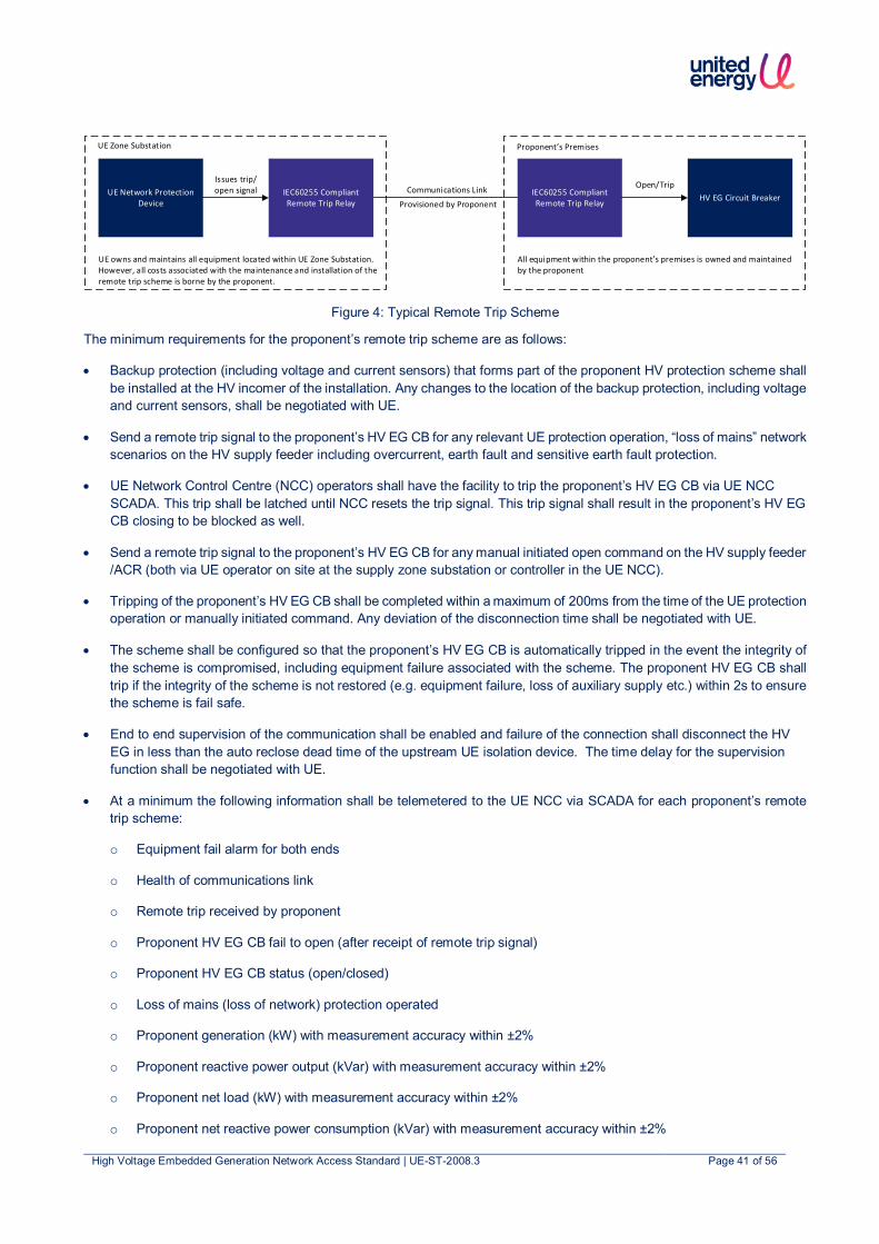
High Voltage Embedded Generation Network Access Standard | UE-ST-2008.3 Page 41 of 56
Figure 4: Typical Remote Trip Scheme
The minimum requirements for the proponent’s remote trip scheme are as follows:
• Backup protection (including voltage and current sensors) that forms part of the proponent HV protection scheme shall be installed at the HV incomer of the installation. Any changes to the location of the backup protection, including voltage and current sensors, shall be negotiated with UE.
• Send a remote trip signal to the proponent’s HV EG CB for any relevant UE protection operation, “loss of mains” network scenarios on the HV supply feeder including overcurrent, earth fault and sensitive earth fault protection.
• UE Network Control Centre (NCC) operators shall have the facility to trip the proponent’s HV EG CB via UE NCC SCADA. This trip shall be latched until NCC resets the trip signal. This trip signal shall result in the proponent’s HV EG CB closing to be blocked as well.
• Send a remote trip signal to the proponent’s HV EG CB for any manual initiated open command on the HV supply feeder /ACR (both via UE operator on site at the supply zone substation or controller in the UE NCC).
• Tripping of the proponent’s HV EG CB shall be completed within a maximum of 200ms from the time of the UE protection operation or manually initiated command. Any deviation of the disconnection time shall be negotiated with UE.
• The scheme shall be configured so that the proponent’s HV EG CB is automatically tripped in the event the integrity of the scheme is compromised, including equipment failure associated with the scheme. The proponent HV EG CB shall trip if the integrity of the scheme is not restored (e.g. equipment failure, loss of auxiliary supply etc.) within 2s to ensure the scheme is fail safe.
• End to end supervision of the communication shall be enabled and failure of the connection shall disconnect the HV EG in less than the auto reclose dead time of the upstream UE isolation device. The time delay for the supervision function shall be negotiated with UE.
• At a minimum the following information shall be telemetered to the UE NCC via SCADA for each proponent’s remote trip scheme:
o Equipment fail alarm for both ends
o Health of communications link
o Remote trip received by proponent
o Proponent HV EG CB fail to open (after receipt of remote trip signal)
o Proponent HV EG CB status (open/closed)
o Loss of mains (loss of network) protection operated
o Proponent generation (kW) with measurement accuracy within ±2%
o Proponent reactive power output (kVar) with measurement accuracy within ±2%
o Proponent net load (kW) with measurement accuracy within ±2%
o Proponent net reactive power consumption (kVar) with measurement accuracy within ±2%
UE Network Protection Device
IEC60255 Compliant Remote Trip Relay
Issues trip/open signal IEC60255 Compliant
Remote Trip Relay HV EG Circuit BreakerOpen/Trip
UE Zone Substation Proponent’s Premises
Communications Link
Provisioned by Proponent
All equipment within the proponent’s premises is owned and maintained by the proponent
UE owns and maintains all equipment located within UE Zone Substation. However, all costs associated with the maintenance and installation of the remote trip scheme is borne by the proponent.

High Voltage Embedded Generation Network Access Standard | UE-ST-2008.3 Page 42 of 56
o Additional voltage, current or power quality parameters such as harmonics, flicker, voltage dips and swells may be required. These will be negotiated as part of the application process.
8.6.3 Special Operational Conditions The following HV EG protection is required for special UE network operational conditions:
• Live line work by UE
When works are undertaken near or on live HV distribution feeders, UE enables a live line operating mode which disables automatic reclose and enables low set instantaneous overcurrent and earth fault protection. With live line mode enabled, grading may be compromised with downstream protection (including the protection associated with the HV EG installation). If the proponent wishes to operate their HV non-IES EG when live line mode is enabled, the HV EG protection will also need to act much more quickly to disconnect from the network for phase-phase faults on the HV feeder while live line sequence is enabled. As such, additional requirements may be required and shall be negotiated with UE as part of the application.
• Total Fire Ban (TFB) Days
For HV EG installed in areas that may experience TFB restrictions, if the proponent chooses to operate their HV EG on TFB days, the HV EG will be required to disconnect instantaneously to avoid contribution to a fault. As such, additional requirements may be required and shall be negotiated with UE as part of the application.
• Short term parallel
UE requires the same analysis for both short term paralleling with the UE network as it does for continuous parallel operation of a HV EG. This is because the consequences of mal-operation are the same for short term parallel operation as with continuous operation. HV EG shall include a backup system to automatically disconnect the HV EG during a short term parallel in the event of a failure paralleling control scheme (i.e. extended parallel protection). HV EG will require protection as per above Table 14 if the extended parallel protection exceed 100ms to disconnect the HV EG.
• Portable HV EG parallel operation
It is necessary to have critical protection and control systems as part of the permanent installation. See sections 8.6.2.1 and 8.6.2.2 for the required protection.
8.6.4 Switchgear and control gear requirements The switchgear and control gear associated with the HV non-IES EG connection shall be:
• Compliant to all relevant standards, codes legislations and regulations listed in section 3
• Switchgear – appropriate breaking and thermal capacities based on the fault level at the switchgear location. Refer to Figure 3 below (this is extracted from Table 5 of the Electricity Distribution Code) for the maximum HV fault level. Site specific fault level at proponent POC can be obtained from UE.
Figure 5: Fault levels extracted from the Electricity Distribution Code5
• EG isolation – All EG shall have a lockable isolating device owned and operable by the proponent.
5 https://www.esc.vic.gov.au/electricity-and-gas/codes-guidelines-and-policies/electricity-distribution-code
High Voltage Embedded Generation Network Access Standard | UE-ST-2008.3 Page 43 of 56
8.6.5 Interlocking • Where multiple HV EG exists downstream of the HV point of connection, suitable control and protection schemes shall
be installed to ensure safe parallel operation inclusive of protection functions in Table 13 and Table 14.
• When connecting an islanded HV non-IES EG system to the network, synchronisation check protection shall be implemented.
8.7 Operating Voltage and Frequency UE has an obligation to maintain the network voltage in compliance to the Distribution Code. Introduction of HV non-IES EG to the network may impact the network voltage and deviate it beyond the limits of the Distribution Code. The EG shall not adversely affect the voltage at the point of connection (POC) such that the voltage deviates beyond the limits of the Electricity Distribution Code.
The HV EG system shall operate at the frequency ranges in compliance with AEMC’s Frequency Operating Standard.
It is the responsibility of the proponent to maintain the voltage of the HV and LV electrical reticulation within the proponent premises.
8.8 Metering Metering shall be installed as per Victorian Service and Installation Rules6.
8.9 Power Quality HV non-IES EG have power quality response capability to either maintain the power quality at the point of connection or provide support to the network. HV non-IES EG shall comply with the applicable power quality requirements of the AS/NZS 61000 series as well as relevant Victoria regulations (e.g. Victorian Distribution Code) and licence conditions, including but not limited to:
• Network voltage control
• Voltage fluctuations
• Harmonics
• Voltage balance
8.9.1 HV Non-IES Voltage Response Modes HV non-IES EG can be configured with either of the following modes:
• Fixed power factor control mode
• Voltage control mode
• Reactive control mode
The voltage response mode configured for HV non-IES EG shall be negotiated with UE as part of the application process as it is dependent on network characteristics at the point of connection.
8.9.2 Network Ancillary Services AEMO is responsible for maintaining the network frequency close to 50Hz in accordance with the NEM frequency standards and for keeping the voltage within an acceptable range at particular nodes on the transmission network and for scheduling power flow between regions while maintaining power flows within the capability of plant. AEMO achieves these objectives by dispatching scheduled generation to match the load and via ancillary services.
6 http://www.victoriansir.org.au/

High Voltage Embedded Generation Network Access Standard | UE-ST-2008.3 Page 44 of 56
Ancillary services can be one of the following:
• Frequency Control Ancillary Services (FCAS)
• Network Control Ancillary Services (NCAS)
• System Restart Ancillary Services (SRAS)
In practice FCAS and NCAS are offered by HV EGs by providing either real power or reactive power reserves that may be required in response to a network fluctuation, disturbance or event or based on load flows to provide local network support. Any HV EG has the option to provide ancillary services.
HV non-IES EG participating in network ancillary services has the potential to rapidly change network load, resulting in significant voltage impact on the local network. Hence, the HV non-IES EG shall adopt necessary controls to prevent adverse impacts on the power quality at the point of connection while generating to provide ancillary services.
8.10 HV Embedded Network It is the responsibility of the proponent to maintain the voltage of the HV and LV electrical reticulation within the proponent premises as per the Electricity Distribution Code. The proponent is also responsible for the operation of the EG system downstream of the HV POC.
8.11 Communications Systems For HV non-IES EG systems requiring remote trip schemes, the communication requirements are outlined in Section 8.6.2.2.
For all other HV non-IES EG systems, UE does not require the proponent to provide any remote monitoring data to UE. However, proponents shall install remote monitoring of their HV non-IES EG systems to ensure that the proponent is promptly notified of issues with their HV non-IES EG systems. Remote monitoring of HV non-IES EG systems by the proponent may be achieved via use of the HV non-IES EG manufacturer’s software applications.
8.12 Data and Information
8.12.1 Static Data and Information The static data and information shall be provided by the proponent to UE as listed in Appendix D: Static Data and Information. UE will provide this data to AEMO’s Distributed Energy Resource Register (DERR) on behalf of the proponent.
8.12.2 Dynamic Data and Information For HV non-IES EG systems requiring remote trip schemes, the dynamic data requirements are outlined in Section 8.6.2.2.
8.13 Cybersecurity The HV EG settings shall be secured against inadvertent or unauthorised tampering. Changes to the HV EG settings shall require the use of tools (e.g. special interface devices and passwords) and special instructions not provided to unauthorised personnel.

High Voltage Embedded Generation Network Access Standard | UE-ST-2008.3 Page 45 of 56
8.14 Technical Studies Technical studies shall be completed as part of the connection application as per Table 10.
Table 17: Technical Studies Required for HV EG IES Connections
Technical Studies HV EG IES
Power Flow Study ‒
Fault Level Contribution Study
Protection Study
Power Quality Impact Study (including harmonics, flicker, voltage step change, unbalance)
‒
Earthing Study ‒
Dynamic System Studies (see Section 8.14.5) ‒
Symbols are used to denote technical studies requirements, where:
Represents that technical studies shall be required ‒ Represents that technical studies may be required
As part of the application process, UE shall provide the following network data to enable the proponent to complete the required technical studies:
• network fault levels up to the point of common coupling
• network model
• network protection information for UE assets (e.g. protection settings)
• network equipment information for UE assets (e.g. line and conductor ratings)
Where one or more of the technical studies does not meet the assessment criteria, UE shall provide the proponent feedback on components of the submission that require further work. The proponent has the option to discuss with UE:
• Alternative configurations of the HV EG IES systems
• Network augmentation (and associated cost of network augmentation)
8.14.1 Power Flow Study The requirement for a power flow study shall be negotiated with UE as part of the application process. Typically this is required for larger installations where there may be thermal impacts to UE’s distribution network or where there are impacts on the proponent’s maximum demand.
8.14.2 Power Quality Impact Studies The requirement for this study shall be negotiated with UE as part of the application process.
8.14.3 Fault Level Contribution Study and Protection Settings Report A comprehensive protection study is required for all HV EG installations. The fault level contribution and protection settings shall be included in this study. Please refer to UE-FM-5001 EG Application Form (Non-Registered) for additional information. This form can be found on UE’s website.
8.14.4 Earthing Study An earthing study is required if alterations or additions are made to the proponent’s HV network.
High Voltage Embedded Generation Network Access Standard | UE-ST-2008.3 Page 46 of 56
8.14.5 System studies Steady state study
The following steady state studies may be required for HV EG applications:
• Power Flow Study (including network contingency analysis where applicable)
• Fault Level Contribution Study (including network contingency analysis where applicable)
• Protection Study (including network contingency analysis where applicable)
• Power Quality Impact Study (including harmonics, flicker, voltage step change, unbalance, network contingency analysis where applicable)
The proponent shall negotiate with UE to determine the required steady state studies for their application,
Dynamic study
Dynamic studies may be required depending on the following:
• outcome of steady state studies,
• presence of non-standard design features as part of the HV EG connection (e.g. STATCOM)
• location of the HV EG on the network
The studies may include:
• Transient/step frequency disturbance
• Transient/step voltage fluctuation
• Generator stability
• Generator governor control/excitation control
• Frequency response
• Fault ride through
The dynamic study requirements shall be negotiated with UE as part of the application process.

High Voltage Embedded Generation Network Access Standard | UE-ST-2008.3 Page 47 of 56
9. Testing and Commissioning for HV non-IES EG Testing and commissioning of the HV non-IES EG installation shall be undertaken by the proponent in accordance with AS 2067, AS/NZS 3000, the equipment manufacturer’s specifications and to the technical requirements stipulated in this document. The testing and commissioning results shall demonstrate that the installed HV non-IES EG system meets the requirements of the connection agreement.
Note these tests shall be installation tests and not type tests of the equipment.
In addition, the following requirements for network connection of HV non-IES EG systems shall be met:
1. Testing and commissioning plan shall be produced by the proponent covering all newly installed equipment, interfaces with existing equipment and end to end testing of remote trip scheme (if installed). The plan shall be produced based on the sequence of testing on site.
2. All tests shall be provided in a test report format or ITP format with reference made to the commissioning plan. The test report shall clearly indicate pass/fail criteria for each test.
3. Pre-commissioning shall be undertaken to prove the functionality of the complete scheme.
4. The results of all testing and commissioning activities shall be thoroughly documented and shall align with the commissioning plan.
5. Testing and commissioning acceptance shall be signed off by a suitably qualified and authorised person.
6. Testing and commissioning acceptance may require UE to carry out witnessing at the proponent’s expense.
Table 18: Testing and Commissioning Requirements for HV non-IES EG Connections
Testing and commissioning submission HV non-IES EG
Exporting Non-exporting
Protection settings and performance1 ≤
HV switchgear integrity and performance ≤
CTs and VTs performance test results ≤
Power quality settings and performance ‒ ‒
Export limits settings and performance ‒
Earth grid in compliance to AS 2067:2016 ‒ ‒
Communications performance for monitoring system2
Site Maintenance Procedure ≤ ≤
Safety and Operating Procedure ≤ ≤
Confirm system is as per specifications ≤ ≤
Confirm single line diagram is located on site ≤ ≤
As-built documentation and drawings ≤ ≤
Certificate of Electrical Safety (CES) ≤ ≤
UE HV EG Commissioning Form (see Appendix D) ≤ ≤
Symbols are used to denote testing and commissioning requirements, where:
Represents that testing and commissioning shall be required
‒ Represents that testing and commissioning may be required

High Voltage Embedded Generation Network Access Standard | UE-ST-2008.3 Page 48 of 56
Notes:
1. Protection Settings and Performance
• The HV non-IES EG protection relay shall be tested by secondary injection. All necessary functional tests shall be carried out to prove that the protection and control schemes operate as per the design.
2. Communications schemes for monitoring
• End to end testing of monitoring data points are required.
• Where remote tripping is required, full end-to-end testing of the remote trip scheme is required.

High Voltage Embedded Generation Network Access Standard | UE-ST-2008.3 Page 49 of 56
10. Operations and Maintenance HV EG systems shall be operated and maintained to ensure compliance with their connection agreement and all legislation, codes, and/or other regulatory instruments at all times. The operations and maintenance requirements for HV EG connections, includes:
1. The HV EG system shall be operated and maintained to ensure compliance with the connection agreement and all legislation, codes, and/or other regulatory instruments at all times
2. Confirmation that maintenance of the HV EG system has been completed shall be submitted to UE by the proponent at a specified interval as agreed with UE
The following documentation is to be kept at the HV EG installation in compliance with relevant codes and is to be readily accessible by UE’s representatives:
• A single line diagram showing all electrical metering points, protection functions and zone of coverage.
• A record of all approved protection settings.
• A copy of the approved operating procedures.
• Maintenance plan and records.
In addition, the proponent shall:
1. Maintain and operate the HV EG installation in a safe condition
2. Ensure that any changes to the HV EG installation are performed by an electrician lawfully permitted to do the work and that the proponent holds a Certificate of Electrical Safety (CES) issued in respect of any of the changes
3. Seek UE approval prior to altering the connection in terms of an addition, upgrade, extension, expansion, augmentation or any other kind of alteration, including any changes to protection functions or settings.
If any breach of this technical standard is suspected, UE may undertake an investigation. If the investigation reveals a breach, the proponent shall be required to rectify this breach and pay UE for the costs associated with the investigation and associated works undertaken by UE.

High Voltage Embedded Generation Network Access Standard | UE-ST-2008.3 Page 50 of 56
Appendix A: Deviations from the National DER Connection Guidelines
Table 19 Table of deviations from National DER Connection Guidelines
Section Description of deviation Type of deviation Justification
1.1 All HV EG connections are to be three phase. In addition, the minimum system capacity for HV non-IES EG system is to be greater than 30kVA. There requirements are not stipulated in the National DER MV and HV EG Connection Guideline.
Promote improved benefits to Australia’s electricity system
Promotes clarity on HV EG connection by differentiating requirements from the LV EG connection
1.3 Added additional obligations f to h To meet jurisdictional requirement
To ensure the proponents meets the jurisdictional requirements
2.1 Definition of IES is different from the National DER LV EG Connection Guideline
To meet jurisdictional requirement
The definition was amended to align with AS/NZS 4777.1:2016
2.1 Added definition of a HV customer Promote improved benefits to Australia’s electricity system
c who is considered a HV customer
2.3 Terminology of the word ‘may’ and ‘should’ were swapped as described in the National DER MV and HV EG Connection Guideline
Promote improved benefits to Australia’s electricity system
Clarifies requirements for proponents
3.2 Added additional requirements for HV EG installed in REFCL protected network areas
To meet jurisdictional requirement
To ensure the proponents meets the jurisdictional requirements
4 (5 in ENA
guide)
Moved Fees and Charges section from section 5 as shown in ENA Guideline to section 4
Promote improved benefits to Australia’s electricity system
Promotes readability and easier reference with sections 1 – 4 being common to both IES and non-IES EG
5 – 10 (4, 6 and 7
in ENA guide)
Created Part A for IES specific requirements and Part B for non-IES specific requirements. This is different to the approach from ENA guideline where IES and non-IES requirements were combined in the various sections
Promote improved benefits to Australia’s electricity system
Promotes readability and easier reference with dedicated sections for IES and non-IES EG specific requirements
5.3.1, 8.3.1 (4.3.1
in ENA guide)
Specific export limit was stipulated instead of export limit to be determined at the time of application as stated in the National DER MV and HV EG Connection Guideline.
Promote improved benefits to Australia’s electricity system
To facilitate HV EG connections by streamlining the assessment process whilst not adversely impacting the network

High Voltage Embedded Generation Network Access Standard | UE-ST-2008.3 Page 51 of 56
Section Description of deviation Type of deviation Justification
5.4 (4.4 in ENA guide)
Excluded items 3b – 3d as the National DER MV and HV EG Connection Guideline stated preferably instead of a requirement
To meet jurisdictional requirement
To ensure the proponents meets the jurisdictional requirements
5.7.2, 8.6.2 (4.7.2
in ENA guide)
Replaced central protection terminology used in National DER MV and HV EG Connection Guideline with backup protection
Promote improved benefits to Australia’s electricity system
Promotes clarity on protection requirements
5.7.3, 8.6.4
Added an additional section on switchgear and control gear requirements
To meet jurisdictional requirement
To ensure associated equipment with HV EG are compliant with AS and international standards
5.10.2, 8.11.2
Added an additional section on network ancillary services requirements
Promote improved benefits to Australia’s electricity system
To ensure system stability when the HV EG provides network ancillary services
5.11, 8.12
Added an additional section on HV connections with multiple tenancies / EG downstream of HV POC
Promote improved benefits to Australia’s electricity system
To ensure EG downstream of HV POC will not adversely impact the network
5.12, 8.13
(4.11 in ENA
guide)
Communication requirements are not based on export level as in the National DER MV and HV EG Connection Guideline. It is based on remote trip requirement.
Promote improved benefits to Australia’s electricity system
Promotes clarity on communication requirements to only systems that require remote trip

High Voltage Embedded Generation Network Access Standard | UE-ST-2008.3 Page 52 of 56
Appendix B: Connection Arrangement Requirements Typical HV EG configuration with no export limit conditions imposed
Figure 6: Typical HV EG installation with no export limit conditions imposed

High Voltage Embedded Generation Network Access Standard | UE-ST-2008.3 Page 53 of 56
Typical HV EG configuration with export limit conditions imposed at LV
Figure 7: Typical HV EG installation with export limit conditions imposed at LV

High Voltage Embedded Generation Network Access Standard | UE-ST-2008.3 Page 54 of 56
Typical HV EG configuration with export limit conditions imposed at HV
Figure 8: Typical HV EG installation with export limit conditions imposed at HV

High Voltage Embedded Generation Network Access Standard | UE-ST-2008.3 Page 55 of 56
Appendix C: Sample Offer to Connect A sample offer to connect can be found on UE’s website7.
For non-registered HV EG customers, please refer to the document titled: Chapter 5A Distribution Connection Embedded Generator Agreement – Sample
For registered HV EG customers, please refer to the document titled: Chapter 5 Distribution Connection Embedded Generator Agreement – Sample
7 https://www.unitedenergy.com.au/industry/solar-energy/negotiated/

High Voltage Embedded Generation Network Access Standard | UE-ST-2008.3 Page 56 of 56
Appendix D: Static Data and Information Static data and information to be provided by the proponent on the HV EG connection can be found on UE’s website8.
For non-registered HV EG customers, please refer to the form titled: UE-FM-5001 EG Application Form (Non-Registered)
For registered HV EG customers, please refer to the form titled: Detailed Enquiry Form (Registered)
For HV EG IES connections, please refer to the form titled: UE-FM-5003 IES Commissioning Form
For HV non-IES EG connections, please refer to the form titled: UE-FM-5004 Non-IES Commissioning Form
For HV connections with both IES and non-IES EG, please refer to the form titled: UE-FM-5005 Combined Commissioning Form
8 https://www.unitedenergy.com.au/industry/solar-energy/negotiated/

UE-ST-2008.3 HV EG Network AccessStandardFinal Audit Report 2020-12-21
Created: 2020-12-16
By: Kaisui Tnay ([email protected])
Status: Signed
Transaction ID: CBJCHBCAABAA3SN_CtKmY5qkh-B9E722TqD3wDMwZI3G
"UE-ST-2008.3 HV EG Network Access Standard" HistoryDocument created by Kaisui Tnay ([email protected])2020-12-16 - 00:06:16 GMT- IP address: 202.125.86.254
Document e-signed by Kaisui Tnay ([email protected])Signature Date: 2020-12-16 - 00:06:48 GMT - Time Source: server- IP address: 202.125.86.254
Document emailed to Darshana Paranagama ([email protected]) for signature2020-12-16 - 00:06:50 GMT
Email viewed by Darshana Paranagama ([email protected])2020-12-16 - 01:12:49 GMT- IP address: 202.125.86.254
Document e-signed by Darshana Paranagama ([email protected])Signature Date: 2020-12-16 - 01:13:05 GMT - Time Source: server- IP address: 202.125.86.254
Document emailed to Christopher Roberts ([email protected]) for signature2020-12-16 - 01:13:07 GMT
Email viewed by Christopher Roberts ([email protected])2020-12-16 - 02:18:43 GMT- IP address: 202.125.86.254
Document e-signed by Christopher Roberts ([email protected])Signature Date: 2020-12-16 - 02:18:54 GMT - Time Source: server- IP address: 202.125.86.254
Document emailed to Rosh Sivanathan ([email protected]) for signature2020-12-16 - 02:18:56 GMT
Email viewed by Rosh Sivanathan ([email protected])2020-12-20 - 23:45:49 GMT- IP address: 202.125.86.254

Document e-signed by Rosh Sivanathan ([email protected])Signature Date: 2020-12-21 - 04:23:25 GMT - Time Source: server- IP address: 202.125.86.254
Document emailed to Robert Simpkin ([email protected]) for signature2020-12-21 - 04:23:27 GMT
Email viewed by Robert Simpkin ([email protected])2020-12-21 - 05:05:11 GMT- IP address: 202.125.86.254
Document e-signed by Robert Simpkin ([email protected])Signature Date: 2020-12-21 - 05:05:50 GMT - Time Source: server- IP address: 202.125.86.254
Agreement completed.2020-12-21 - 05:05:50 GMT


