GE Power Controls range of H.V. HBC fuse links meet the dimensional requirements of BS2692-1986/IEC282 1994. These fuselinks also conform to IS 9385-Part 1-1979. The fuse links are particularly suitable for fitting into H.V. ring main units. This range may also be used in air, details of free air ratings are availble on request. The maximum values of breaking capacity quoted are test values which may be limited by test station capability or the economics of testing. Generally the fuse link capability will be considerably higher and no practical limit is imposed on these fuse links for maximum breaking capacity under service conditions. Excellent performance is provided under low overcurrent conditions. For the majority of ratings the minimum breaking current of the fuse link is between 2 and 3 times the rated current of the fuse link. This is made possible by the use of low melting point alloy which is applied to the centre of the elements thus ensuring that unacceptable temperatures are not reached during the prolonged pre-arcing period. The striker functions normally for all currents down to minimum melting current. Where the H.V fuse link co-ordinates with an over current protective device, for example, expulsion fuse or overload relay, then the minimum breaking current must be lower than the intersection of the prospective time/current characteristics. Where instantaneous striker operated tripping of H.V. fuse switch combinations is employed then the minimum breaking current of the H.V. fuse link must be less than the maximum interrupting current of the associated switch. Fuselink for Distribution Circuit (for use in oil) - Type KEMXO & KEBXO A.C. short circuit performance Low overcurrent performance It should be stressed that use of a fuselink having too high a value of minimum breaking current, could under certain circumstances, result in disruptive failure of the fuselinks and consequent damage, arising out of fuselink clearing faults below the minimum breaking current. The time/current characteristics relate to mean pre-arcing time and are accurate to within a manufacturing tolerance of + 10% related to current. The cut-off current characteristics show the maximum peak current a given fuse link will permit for various fault currents. The minimum pre-arcing I2t values given are for adiabatic conditions and in service pre-arcing values will normally be higher. The total I2t values given are obtained during tests under the most onerous conditions. They are particularly affected by applied voltage in and in service the values will generally be much less than those quoted. Because the total I2t / prospective current characteristic tends towards a constant value, the figures quoted will also apply to prospective current greater than the maximum tested breaking capacity. The overvoltage produced by the fuselink during the arcing period is limited by values in the appropriate standards. These fuselinks have maximum values well within the standard and can thus generally be used at a voltage level one step down in the table listed here. For example the 12kV class may be used on 7.2kV systems and short circuit tests have been conducted to verify that the arc voltage remains with the limit for 7.2 kV. Fuse links are generally equipped with a striker pin which can be used to indicate fuse link operation or to operate a trip mechanism where provided. The striker pin, which is actuated by a small pyrotechnic device, has characteristics as per IEC 282- 1994. This requires a projection of 10mm minimum/16mm maximum from the end face of the fuse link and during this travel an energy output of 2±1 joules must be produced. These fuse links are designed to produce energy towards the upper end of this band. A lockout feature is also incorporated with a minimum withstand force of 40 Newtons, which can be required to hold the trip bar of an associated switch in the locked out position. This prevents reclosure of the switch until the fuse links have been replaced. Characteristics Arc voltage Striker pins Available ranges Maximum 3-phase Service voltage kV R.M.S. Fuse type The letter X denotes a striker and is omitted in non striker version Current rating in Amps Breaking capacity* kA R.M.S. SYM. 12 KEBXO 5,10,16,20,25, 20+# 36,40,45,50,63,80 12 KEMXO 5,10,16,20,25,36, 20+ 40,45,50,56, 63,80,90 12 KEMXO 100,120, 40 * Breaking capacity quoted are test values and apply at the maximum voltage rating. + These ratings certified to more onerous requirements with actual test voltages at least equal to rated voltage. +# Additional tests carried out for breaking capacity of 40kA at 7.2kV. High Voltage HBC Fuselinks E 179 High voltage HBC fuselinks
Transcript
GE Power Controls range of H.V. HBC fuse links meet the dimensional requirements of BS2692-1986/IEC282 1994. These f u s e l i n k s a l s o c o n f o r m t oIS 9385-Part 1-1979.
The fuse links are particularly suitable for fitting into H.V. ring main units.This range may also be used in air, detailsof free air ratings are availble on request.
The maximum values of breaking capacityquoted are test values which may belimited by test station capability or theeconomics of testing. Generally the fuselink capability will be considerably higherand no practical limit is imposed on thesefuse links for maximum breaking capacityunder service conditions.
Excellent performance is provided underlow overcurrent conditions. For themajority of ratings the minimum breaking current of the fuse link is between 2 and 3 times the rated current of the fuse link. This is made possible by the use of low melting point alloy which is applied to the centre of the elements thus ensuring that unacceptable temperatures are not reached during the prolonged pre-arcing period. The striker functions normally for all currents down to minimum melting current.Where the H.V fuse link co-ordinates withan over current protective device, forexample, expulsion fuse or overload relay,then the minimum breaking current mustbe lower than the intersection of theprospective time/current characteristics.Where instantaneous striker operatedtripping of H.V. fuse switch combinationsis employed then the minimum breakingcurrent of the H.V. fuse link must be lessthan the maximum interrupting current ofthe associated switch.
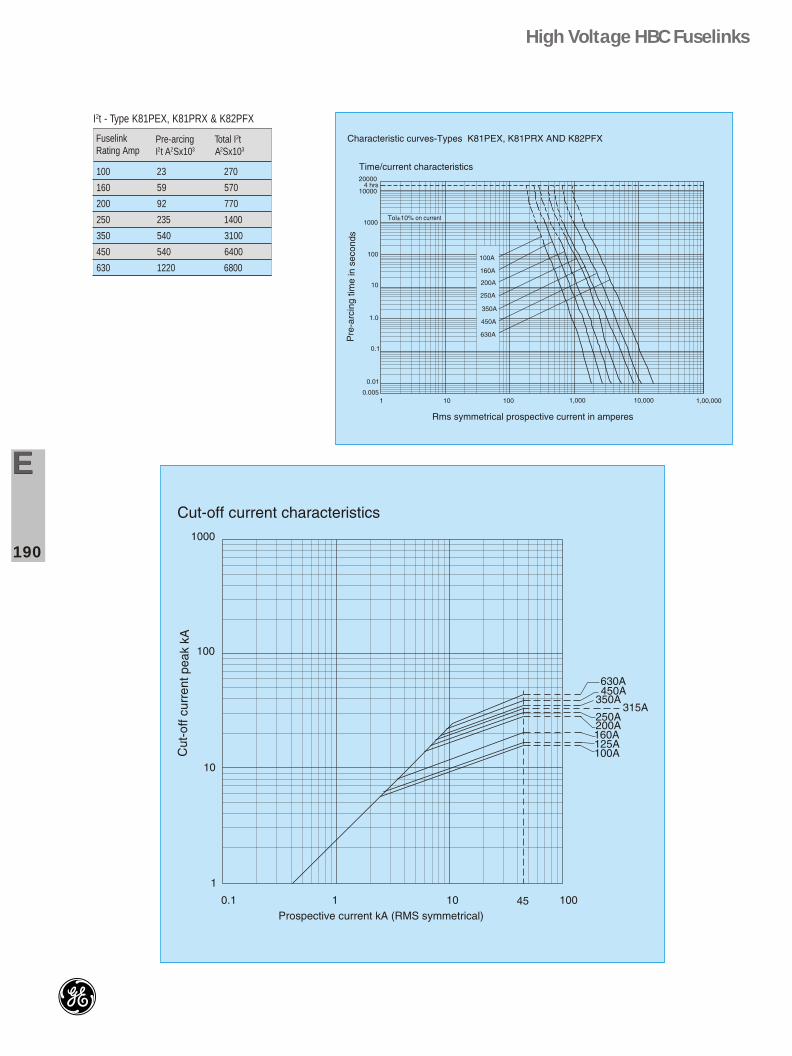
Fuselink for Distribution Circuit (for use in oil) - Type KEMXO & KEBXO
A.C. short circuit performance
Low overcurrent performance
It should be stressed that use of a fuselink having too high a value of minimum breaking current, could under certain circumstances, result in disruptive failure of the fuselinks and consequent damage, arising out of fuselink clearing faults below the minimum breaking current.
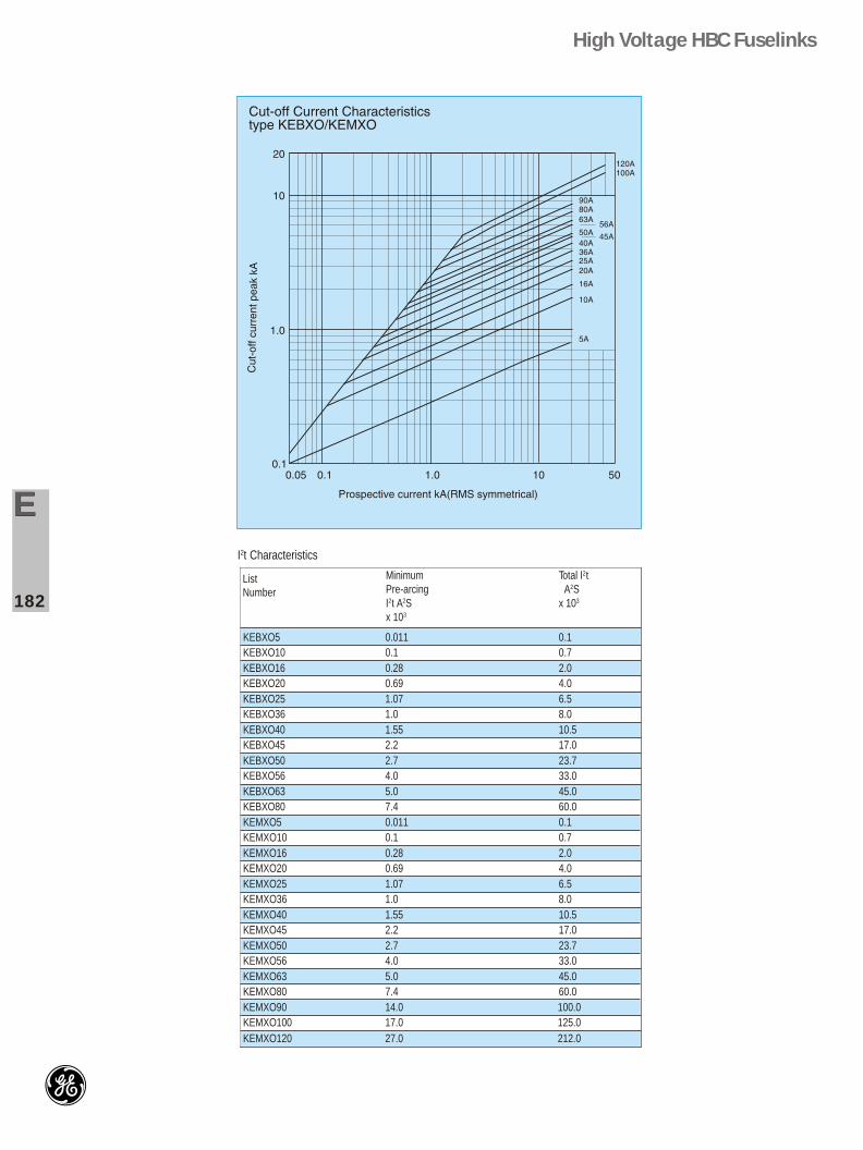
The time/current characteristics relate to mean pre-arcing time and are accurate to within a manufacturing tolerance of + 10% related to current.The cut-off current characteristics show the maximum peak current a given fuse link will permit for various fault currents.The minimum pre-arcing I2t values given are for adiabatic conditions and in servicepre-arcing values will normally be higher.The total I2t values given are obtained during tests under the most onerousconditions. They are particularly affected by applied voltage in and in service thevalues will generally be much less than those quoted. Because the total I2t /prospective current characteristic tends towards a constant value, the figures quoted will also apply to prospective current greater than the maximum tested breaking capacity.
The overvoltage produced by the fuselink during the arcing period is limited byvalues in the appropriate standards. These fuselinks have maximum values wellwithin the standard and can thus generally be used at a voltage level one step downin the table listed here. For example the 12kV class may be used on 7.2kV systemsand short circuit tests have been conducted to verify that the arc voltage remainswith the limit for 7.2 kV.
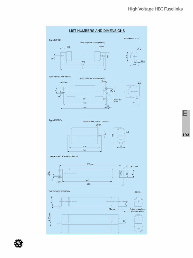
Fuse links are generally equipped with a striker pin which can be used to indicatefuse link operation or to operate a trip mechanism where provided. The striker pin,which is actuated by a small pyrotechnic device, has characteristics as per IEC 282-1994. This requires a projection of 10mm minimum/16mm maximum from the endface of the fuse link and during this travel an energy output of 2±1 joules must beproduced. These fuse links are designed to produce energy towards the upper endof this band. A lockout feature is also incorporated with a minimum withstand forceof 40 Newtons, which can be required to hold the trip bar of an associated switch inthe locked out position. This prevents reclosure of the switch until the fuse linkshave been replaced.
Characteristics
Arc voltage
Striker pins
Available ranges
Maximum3-phaseService voltagekV R.M.S.
Fuse typeThe letter Xdenotes astriker and isomittedin non strikerversion
* Breaking capacity quoted are test values and apply at the maximum voltage rating.+ These ratings certified to more onerous requirements with actual test voltages at least equal to rated voltage.+# Additional tests carried out for breaking capacity of 40kA at 7.2kV.
High Voltage HBC Fuselinks
EE
179
High voltage HBC fuselinks
In some applications a striker pin is not required: Forexample, fuse links mounted directly into transformertanks and used as back-up protection only.
An essential requirement for a fuse link used under oil isabsolute integrity of the oil seal between end caps andbody. For each end cap, these fuse links incorporatetwo rectangular section rings of high temperature and oilresistant rubber. This feature was first introduced over 40years ago, and is well proven with many thousands offuse links in service throughout the world. Fuse links ofthis type are subject to 100% testing of this feature duringthe course of manufacture. These fuse links meet thetype test oil tightness requirements of BS 2692/IEC282
These fuse links are ideally suitable for HV capacitorprotection also. The basic guidelines for normal circuitapplication are:
1. Where small capacitors are to be protected, the fusecurrent rating must be atleast twice the current rating ofthe capacitor.
2. The fuse link must withstand the capacitor inrushcurrent during switching for a period during which thecapacitor tries to settle down to carry normal current.
This must be checked using the time/current characteristics of the fuse links selected as per 1 above.
3. For large installations where a lot of series/parallelconnections are involved please refer to Works with complete data.
Operation in air
Most of these fuse link may be used in air, in which case thehigher current ratings are subject to derating in respect of rated current.
Transformer circuit applications
The criteria for selection of fuse links for transformer circuitapplications are covered in IEC 787 - 1983. the mainrequirements are shown in Fig.1 and are:
1. The H.V. fuse link must withstand inrush current. For practical purposes this means that the time\current characteristic must be to the right of the point given by 12 times transformer full load current and 0.1 seconds.
2. The in-unit H.V. fuse link current rating must be atleast as high as the permissible overload current of the transformer, assumed to be 150% in the table.
Oil seals
Capacitor Circuit Application
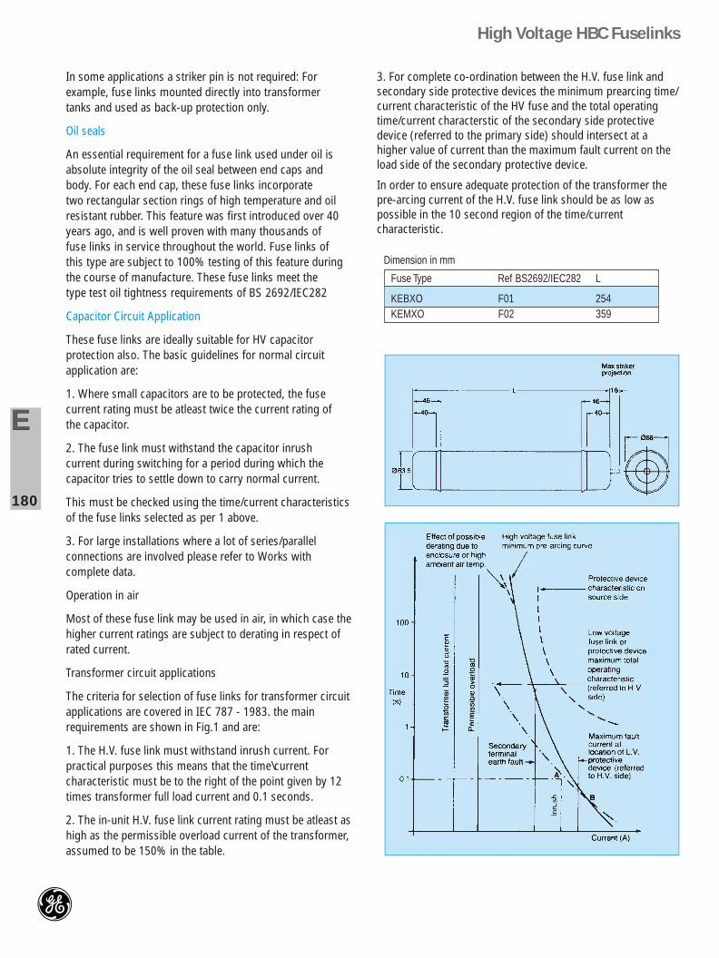
Dimension in mm
Fuse Type Ref BS2692/IEC282 L
KEBXO F01 254KEMXO F02 359
3. For complete co-ordination between the H.V. fuse link andsecondary side protective devices the minimum prearcing time/current characteristic of the HV fuse and the total operatingtime/current characterstic of the secondary side protectivedevice (referred to the primary side) should intersect at ahigher value of current than the maximum fault current on theload side of the secondary protective device.
In order to ensure adequate protection of the transformer thepre-arcing current of the H.V. fuse link should be as low aspossible in the 10 second region of the time/currentcharacteristic.
GE PowerControls high voltage HBC fuselinks suitable for distributioncircuits i.e., for protectingtransformers, cables and capacitors -5 Amps to 100 Amps - 11/12 kVsystems.
The breaking capaciy of type H2CAS/
H3CAS is 36kA at 12 kV to IEC 282-1:1994.
Ideally suited for protecting HVcapacitor circuits, designed towithstand capacitorin-rush currents.
For small capacitors, the fuse ratingmust be at least twice the currentrating of capacitor. For largeinstallations where a lot of series/parallel connections are involved,
please refer to works with completedata.
• Excellent low over-currentperformance.
• Arc-voltage limits permits use in7.2kV System.
• Striker pin operation for trip baroperation/indication.
It should be stressed that use of a fuselink having too high a value of minimum breaking current, could under certain circumstances, result in disruptive failure of the fuselinks and consequent damage, arising out of fuselink clearing faults below the minimum breaking current.
Motor starting applications (Type K)
High voltage fuselinks used in motor circuits must have the ability to withstand, without deterioration, the repeated surges associated with motor starting. Reliability in this respect is essential and must be provided without compromise to other essential parameters of performance and within the bounds of size and economy.
The ability to co-ordinate precisely with contactors and 'upstream' protective devices in the same system, together with adequate short circuit capacity are essential for safety. Fault energy limitation to minimise damage resulting from electrical faults is equally important.
The GE Power Controls range of 3.6kV and 7.2kV fuselinks meets these requirements and represent a significant advance in the design of high voltage fuselinks for motor starting applications. The range has the following advantages:
Higher current rating within single body dimensions.
Proven ability to resist ageing under repeated starting conditions coupled with increased motor starting capability for given ratings.
Lower values of current and energy let-through under maximum fault conditions.
Where fuselinks are used for motor circuit protection in conjuction with contactors, the current rating of the fuselink is usually of secondary consideration. The main criterion in the choice of rating is the ability of the fuselink to withstand repeated starting current surges for the run up time of the motor, without deterioration.
Fuselink selection chart gives recommended fuselink ratings for particular starting currents with variousrun-up times andfrequency of starting.
Ability to withstand motor starting
EE
185
AC short circuit performance
Low overcurrent performance
Characteristics
Application Notes
Method of Selection
¨BS 2692-1986, IEC 282-1-1994 for 45kA, 7.2kV
¨BS 2692-1986, IEC 282-1-1994 for 40kA, 3.6kV
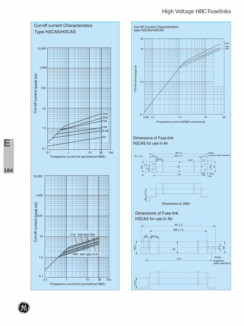
The values of cut-off current and I2t let through are those obtained under the most severe short circuitconditions, specified in IEC 282-1. Arc voltages produced during operation are substantially below the maximum specified in both BS 2692 and IEC. 282-1.
The range has improved performance under low overcurrent conditions and extends considerably the safe operating zone of the fuselink.
Fuselinks should be selected so that the value of minimum breaking current is appropriate to the particular application concerned. Fuselinks guarantee protection against all fault currents ranging from the minimum breaking current to the maximum breaking capacity. The minimum breaking current for each rating is given in the table. It is recommended for a fuselink to be co-ordinated with an overcurrent protective device, an overload relay, with the minimum breaking current always lower than the intersection of the prospective time/current characteristics. It should be stressed that use of a fuselink having too high a value of minimum breaking current, could under certain circumstances, result in disruptive failure of the fuselinks and consequent damage, arising out of fuselink clearing faults below the minimum breaking current.
The time/current characteristics shown relate to mean pre-arcing times and are accurate to within a manufacturing tolerance of ±10% related to current.
These selection charts enable the minimum rating of fuselink to be determined for particular Motor Starting conditions and the following points must be considered in choosing the correct fuselink rating.
1. The number of starts per hour indicated in the charts are based on two of these starts being in immediate succession, the remainder being evenly spaced in the 1 hour period.
The charts indicate a rate of starting : For example 8 starts in 15 min. is respresented as 32 starts per hour.
2. They enable the selection of the lowest rated fuselink to withstand the specified starting conditions. However, it is also necessary to ensure that the fuselink rating is not less than 1.33 times the normal full load current.
It is advisable to replace fuselinks in all the three phases when the fuselink in one or two phases of a three phase circuit has operated, unless it is definitely known that no over-current has passed through the unmelted fuselinks.
(a) Select the chart covering the voltage rating and run-up time of the motor.
(b) Select starting current on the horizontal axis.
(c) Read off on vertical axis fuselink rating corresponding to intersection of starting current and required number of starts per hour line.
Example : Motor with run-up time
6 secs.; 8 starts per hour.
F.L.C. 92A Starting current 552A.
(a) Select Chart A.
(b) Select 552A on horizontal axis.
(c) Read off, on vertical axis, the fuselink rating corresponding to intersection of 552 on the 8 starts per hour line, which in this case is 125A rating.
(d) This fuse rating is greater than 1.33 times 92Amp., motor full-load current, therefore the final fuselinkselection will be 125A rating.
% Increase in Resistance over Base TemperatureResistance measured if > 15 % ( of corrected value for ambient during measurement) will mean atleast one element is broken
1. Please read of the value of resistance on the fuse at the reference temperature, written at the plain end side of the outer cap
2. Observe the ambient temperature at the place of measurement
3. In the chart for resistance increase, locate the temp. as marked as ref. On the fuse. Now locate the new temp. for which the resistance needs be known.
4. Drop a perpendicular from the new temp. to intersect the slanted axis corresponding to the ref. Temp. of measurement. Read off the corresponding value on the X-axis (in %), which indicates the percentage rise on the resistance for the corresponding temperature
5. If the measured value is higher by 15% than the above prescribed resistance increase, then there is a risk of an element break inside and such a fuse is not recommended for service.
For example, for a 12kV, KEMXO 90A fuse, at an ref. Temp. of say 27°C, the marked value on the fuse is, 10.8mohms, And that we need to determine the resistance at a diff. Temp. of say 33°C, then Choose 27 on the Y-axis and choose 33°C on the same Y-axis. Drop a perpendicular from 33°C. This line intersects the slanted axis of 27°C at 2.4% on the X-axis. This indicates that the value measured at 33°C shall be 2.4% increase of the value at 27°C. (10.8+(0.024*10.8) = 0.2592+10.8 = 11.0592m.ohms)
If the measured exceeds 11.0592 by 15% higher, then chances for break of 1 element is present. Such a fuse should not be Put in to service.
High Voltage HBC Fuselinks
EE
192
Relation between ambient temperature and resistance
High Voltage HBC Fuselinks
EE
193
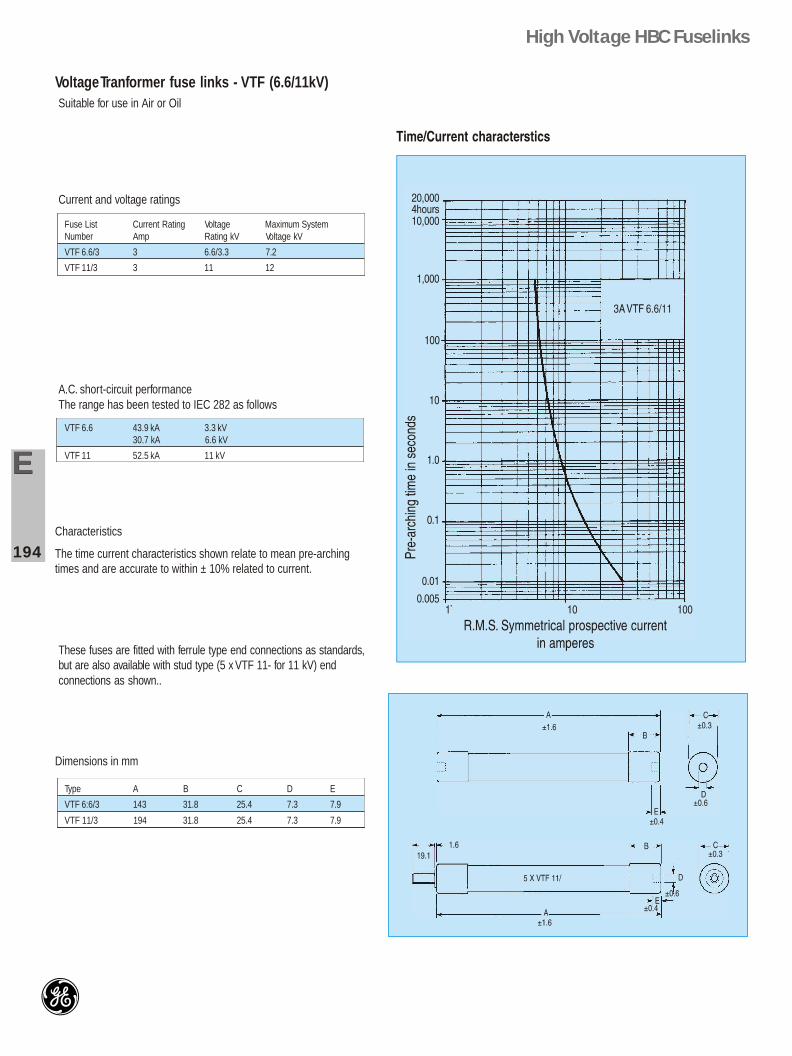
Voltage Tranformer fuse links - VTF (6.6/11kV)Suitable for use in Air or Oil
Current and voltage ratings
Fuse List Current Rating Voltage Maximum SystemNumber Amp Rating kV Voltage kV
VTF 6.6/3 3 6.6/3.3 7.2
VTF 11/3 3 11 12
A.C. short-circuit performanceThe range has been tested to IEC 282 as follows
VTF 6.6 43.9 kA 3.3 kV30.7 kA 6.6 kV
VTF 11 52.5 kA 11 kV
These fuses are fitted with ferrule type end connections as standards,but are also available with stud type (5 x VTF 11- for 11 kV) endconnections as shown..
Characteristics
The time current characteristics shown relate to mean pre-archingtimes and are accurate to within ± 10% related to current.
Type A B C D E
VTF 6:6/3 143 31.8 25.4 7.3 7.9
VTF 11/3 194 31.8 25.4 7.3 7.9
Dimensions in mm
High Voltage HBC Fuselinks
EE
194
Application Guide (reference IEC 60282-2002)
Object
General
Application
Mounting
Dos’ & Donts’
8.1
The object of this clause is to present suggestions on applications, operation and maintenance as an aid in obtaining satisfactory performance with high voltage current limiting fuses
8.2
A fuse is an electric circuit stands guard at all times to protect the circuit and the equipment connected to it from damage within the limits of its ratings. How well this fuse will perform depends not only the accuracy with which it was manufactured, but also upon the correctness of the application and the attention it receives after it is installed. If it is not properly applied and maintained, considerable damage may occur to costly equipment
High voltage fuse-links should be handled with at least with same degree of care as any other precision made itemof equipment (such as a relay). Fuse-links should be stored in their protective packaging until required for use. Any fuse-link dropped or otherwise subjected to severe mechanical shock should be checked before use. The check should include an inspection for damage of the fuse barrel and metal part as a resistance check. A nominal resistance value may usually be obtained from the fuse manufacturer.
If the fuse-link during normal installation and servicve conditions is subject to severe mechanical stresses, for example, shocks, vibration, etc., acting in one or several directions. It should be verified that the fuse link can withstand these stresses without damage or deterioration. Practical tests to prove the mechanical withstand of fuselinks may be carried out by agreement between the user and manufacturer of the fuses and the switchgear. For switch fuse combinations, see IEC 60420
It cannot be stressed too strongly that prescribed safety rules should be observed at all times when manipulating or maintaining fuses near energized equipment or conductors.
8.3
8.3.1
Fuses should be installed in accordance with the manufacturer’s instructions. For multipole arrangements of fuses, when the distance between poles is not fixed by construction, the poles should be mounted with clearances not less than those specified by the manufacturer.
It should be noted that, when fuse-links are subjected to the effect of severe solar radiation, the performance of these fuse-links may be significantly affected
High degree of care needs to be exercised to ensure correctness of applications, handling and maintenance of HV Fuselinks.
Fuselinks should be stored in their original packing until requires to be used.
Any Fuselink dropped or otherwise subjected to severe mechanical shock should be checked.
Fuselinks should not be subjeced to severe mechanical stress, shock or vibrations when installed.