HIGHBAY RAIL 400W INSTALLATION INSTRUCTIONS Thank you for buying RAB lighting fixtures. Our goal is to design the best quality products to get the job done right. We’d like to hear your comments. Call the Marketing Department at 888-RAB-1000 or email: [email protected]TM IMPORTANT READ CAREFULLY BEFORE INSTALLING FIXTURE. RETAIN THESE INSTRUCTIONS FOR FUTURE REFERENCE. Fixtures must be wired in accordance with the National Electrical Code and all applicable local codes. Proper grounding is required for safety. THIS PRODUCT MUST BE INSTALLED IN ACCORDANCE WITH THE APPLICABLE INSTALLATION CODE BY A PERSON FAMILIAR WITH THE CONSTRUCTION AND OPERATION OF THE PRODUCT AND THE HAZARDS INVOLVED. WARNING: Make certain power is OFF before installing or maintaining fixture. No user serviceable parts inside. MOUNTING FIXTURE TO CEILING Mount Housing to sturdy ceiling structure as follows: 1. V Hooks (2) are provided for chain mounting. Secure V Hooks through Bracket Hole at back of Housing as in Fig. 1. 2. Connect to two (2) equal lengths of chain (by others) and/ or appropriate hardware (by others) suitable for mounting surface, to suspend Housing from V Hooks. 3. Fixture mounting height and spacing should be determined by application requirements. Use chain suitable to support four (4) times the weight of the fixture. 4. Brackets (2) should be positioned near end of Housing as shown in Fig.2. Secure Housing to ceiling mounting surface and adjust Brackets evenly to ensure Housing is stabilized. 5. If ordered with LOSBAY800 sensor (suffix /LOS) or similar sensor or LightCloud controller, re-attach pre-wired sensor on Side Cap to Housing. Tighten Side Cap Screw as shown in Fig. 3. 6. Remove one of the Access Plates and feed supply wire with strain relief conduit connector through Access Plate and make electrical connections as shown in wiring diagram. Use approved wiring connectors and wire to local NEC codes. Push all wires back into Housing. Be careful not to pinch wires. 7. Secure Access Plate and tighten Screws (2). Fig. 1 V Hook (2) Bracket (2) Bracket Hole V Hook (2) Screw Access Plate Housing Fig. 2 Fig. 3 Side Cap (2) Side Cap (2) LOSBAY800 Side Cap Screw TM
Transcript
HIGHBAY RAIL 400WINSTALLATION INSTRUCTIONSThank you for buying RAB lighting fixtures. Our goal is to design the best quality products to get the job done right. We’d like to hear your comments. Call the Marketing Department at 888-RAB-1000 or email: [email protected]
TM
IMPORTANTREAD CAREFULLY BEFORE INSTALLING FIXTURE. RETAIN THESE INSTRUCTIONS FOR FUTURE REFERENCE.
Fixtures must be wired in accordance with the National Electrical Code and all applicable local codes. Proper grounding is required for safety. THIS PRODUCT MUST BE INSTALLED IN ACCORDANCE WITH THE APPLICABLE INSTALLATION CODE BY A PERSON FAMILIAR WITH THE CONSTRUCTION AND OPERATION OF THE PRODUCT AND THE HAZARDS INVOLVED.
WARNING: Make certain power is OFF before installing or maintaining fixture. No user serviceable parts inside.
MOUNTING FIXTURE TO CEILINGMount Housing to sturdy ceiling structure as follows:
1. V Hooks (2) are provided for chain mounting. Secure V Hooks through Bracket Hole at back of Housing as in Fig. 1.
2. Connect to two (2) equal lengths of chain (by others) and/or appropriate hardware (by others) suitable for mounting surface, to suspend Housing from V Hooks.
3. Fixture mounting height and spacing should be determined by application requirements. Use chain suitable to support four (4) times the weight of the fixture.
4. Brackets (2) should be positioned near end of Housing as shown in Fig.2. Secure Housing to ceiling mounting surface and adjust Brackets evenly to ensure Housing is stabilized.
5. If ordered with LOSBAY800 sensor (suffix /LOS) or similar sensor or LightCloud controller, re-attach pre-wired sensor on Side Cap to Housing. Tighten Side Cap Screw as shown in Fig. 3.
6. Remove one of the Access Plates and feed supply wire with strain relief conduit connector through Access Plate and make electrical connections as shown in wiring diagram. Use approved wiring connectors and wire to local NEC codes. Push all wires back into Housing. Be careful not to pinch wires.
7. Secure Access Plate and tighten Screws (2).
Fig. 1
V Hook (2)Bracket (2)
Bracket Hole
V Hook (2)
ScrewAccess Plate
Housing
Fig. 2
Fig. 3
Side Cap (2)
Side Cap (2)
LOSBAY800
Side Cap Screw
TM
HIGHBAY RAIL 400WINSTALLATION INSTRUCTIONSThank you for buying RAB lighting fixtures. Our goal is to design the best quality products to get the job done right. We’d like to hear your comments. Call the Marketing Department at 888-RAB-1000 or email: [email protected]
TM
PATENT - US: Patent D761,477
CLEANING & MAINTENANCECAUTION: Be sure fixture temperature is cool enough to touch. Do not clean or maintain while fixture is energized.
1. Lens should be washed in a solution of warm water and any mild, non abrasive household detergent, rinsed with clean water and wiped dry. Do not use chemicals to clean fixture.
2. Do not open fixture to clean the LED. Do not touch the LED.
TROUBLESHOOTING 1. Check that the line voltage at fixture is correct. Refer to
wiring directions.
2. Be sure the fixture is grounded properly.
0-10V DIMMABLE WIRINGUniversal voltage driver permits operation at 120V thru 277V, 50 or 60 Hz. Units ordered with (/480/D10) suffix are 480V, 50Hz or 60Hz. For 0-10V Dimming, follow the wiring directions as in Fig. 4.
1. Connect the black fixture lead to the LINE supply lead.
2. Connect the white fixture lead to the COMMON supply lead.
3. Connect the GROUND wire from fixture to supply ground.
4. Connect the purple fixture lead to the (V+) DIM lead.
5. Connect the gray fixture lead to the (V-) DIM lead.
6. Cap the yellow fixture lead, if present. Do NOT connect. NOTE: Do not connect DIM V+ (purple)/ DIM V- (gray) to line voltage or supply ground.
Easy Answersrabweb.comVisit our website for product info
Note: These instructions do not cover all details or variations in equipment nor do they provide for every possible situation during installation, operation or maintenance.
BILEVEL DIMMER OPTIONFor 100% light output (disabling the dimmer), splice red wire with black line wire.
For chosen output only, leave red wire capped.
For Bilevel Function, connect red wire to switched device.
1. Determine what % light output is desired and set switch prior to installation. Options are: 25%, 50%, and 75%.
2. Connect purple wire with driver’s purple wire.
3. Connect gray wire with driver’s gray wire.
4. Connect black wire with driver and supply line wires.
5. Connect white wire with driver and supply neutral wires.
HIGHBAY RAIL PENDANT 400W/ 52inINSTALLATION INSTRUCTIONSThank you for buying RAB lighting fixtures. Our goal is to design the best quality products to get the job done right. We’d like to hear your comments. Call the Marketing Department at 888-RAB-1000 or email: [email protected]
®
IMPORTANTREAD CAREFULLY BEFORE INSTALLING FIXTURE. RETAIN THESE INSTRUCTIONS FOR FUTURE REFERENCE.Fixtures must be wired in accordance with the National Electrical Code and all applicable local codes. Proper grounding is required for safety. THIS PRODUCT MUST BE INSTALLED IN ACCORDANCE WITH THE APPLICABLE INSTALLATION CODE BY A PERSON FAMILIAR WITH THE CONSTRUCTION AND OPERATION OF THE PRODUCT AND THE HAZARDS INVOLVED. WARNING: Make certain power is OFF before installing or maintaining fixture. No user serviceable parts inside.
MOUNTING FIXTURE TO CEILINGRAIL Pendant 400W is provided with two (2) Pendant Box. Mount Housing to sturdy ceiling structure as follows:
FOR PENDANT MOUNTING 1. Choose equal length of two 3/4” NPS Pendant Stems (supplied
by others) secured to mounting surface using appropriate mounting hardware.
2. Loosen screws (2) and remove Side Panel from each Pendant Box as shown in Fig. 1.
3. Loosen Screws (4) and slide Pendant Box from each Pendant Box Plate/ Housing as shown in Fig. 2a.
4. Secure Pendant Stems to the clearance hole on Pendant Boxes using Locknut and Support Nut (supplied by others) as shown in Fig. 2b. Add thread locking compound and tighten locknut/ nut to prevent fixture rotation.
5. Slide Pendant Boxes onto Pendant Box Plate/ Housing and tighten Screws (4).
6. Feed supply wires through one of the Pendant Stem. Wire the housing leads to supply wires using UL listed wire connectors according to NEC and local codes in the Pendant Box. Push all wires back into Pendant Box. Be careful not to pinch wires.
7. Replace Side Panel and tighten screws (2) as shown in Fig. 1.8. If ordered with LOSBAY800 sensor (suffix /LOS) or similar sensor or
LightCloud controller, re-attach pre-wired sensor on Side Cap to Housing. Tighten Side Cap Screw as shown in Fig. 3.
Pendant Stem (supplied by others)
Fig. 3
Side Cap
LOSBAY800
Side Cap Screw
TM
Locknut (supplied by others)
Support Nut (supplied by others)
slide
Screws (4)
Side Panel
Pendant Box
Housing
Fig. 2a
Fig. 1
Fig. 2b
Pendant Box Plate
FOR SURFACE MOUNTING 1. Follow Step 2 and 3 in For Pendant Mounting section.2. Mount each Pendant Box to ceiling by drilling out Drill Out
Locations as shown on Fig. 4. Use appropriate mounting hardware suitable for the mounting surface.
3. Slide Pendant Boxes onto Pendant Box Plate/ Housing and tighten Screws (4).
4. Wire the housing leads to supply wires using UL listed wire connectors according to NEC and local codes in one of the Pendant Box. Push all wires back into Pendant Box. Be careful not to pinch wires.
5. Replace Side Panel and tighten screws (2) as shown in Fig. 1.6. Follow Step 8 in For Pendant Mounting section, if ordering with
sensor/ controller option.
Only for Pendant Mounting
Housing
HIGHBAY RAIL PENDANT 400W/ 52inINSTALLATION INSTRUCTIONSThank you for buying RAB lighting fixtures. Our goal is to design the best quality products to get the job done right. We’d like to hear your comments. Call the Marketing Department at 888-RAB-1000 or email: [email protected]
®
PATENT - US: Patent D761,477
CLEANING & MAINTENANCECAUTION: Be sure fixture temperature is cool enough to touch. Do not clean or maintain while fixture is energized.
1. Lens should be washed in a solution of warm water and any mild, non abrasive household detergent, rinsed with clean water and wiped dry. Do not use chemicals to clean fixture.
2. Do not open fixture to clean the LED. Do not touch the LED.
TROUBLESHOOTING 1. Check that the line voltage at fixture is correct. Refer to
wiring directions.
2. Be sure the fixture is grounded properly.
0-10V DIMMABLE WIRINGUniversal voltage driver permits operation at 120V thru 277V, 50 or 60 Hz. Units ordered with (/480/D10) suffix are 480V, 50Hz or 60Hz. For 0-10V Dimming, follow the wiring directions as in Fig. 5.
1. Connect the black fixture lead to the LINE supply lead.
2. Connect the white fixture lead to the COMMON supply lead.
3. Connect the GROUND wire from fixture to supply ground.
4. Connect the purple fixture lead to the (V+) DIM lead.
5. Connect the gray fixture lead to the (V-) DIM lead.
6. Cap the yellow fixture lead, if present. Do NOT connect. NOTE: Do not connect DIM V+ (purple)/ DIM V- (gray) to line voltage or supply ground.
Easy Answersrabweb.comVisit our website for product info
Note: These instructions do not cover all details or variations in equipment nor do they provide for every possible situation during installation, operation or maintenance.
BILEVEL DIMMER OPTIONFor 100% light output (disabling the dimmer), splice red wire with black line wire.
For chosen output only, leave red wire capped.
For Bilevel Function, connect red wire to switched device.
1. Determine what % light output is desired and set switch prior to installation. Options are: 25%, 50%, and 75%.
2. Connect purple wire with driver’s purple wire.
3. Connect gray wire with driver’s gray wire.
4. Connect black wire with driver and supply line wires.
5. Connect white wire with driver and supply neutral wires.
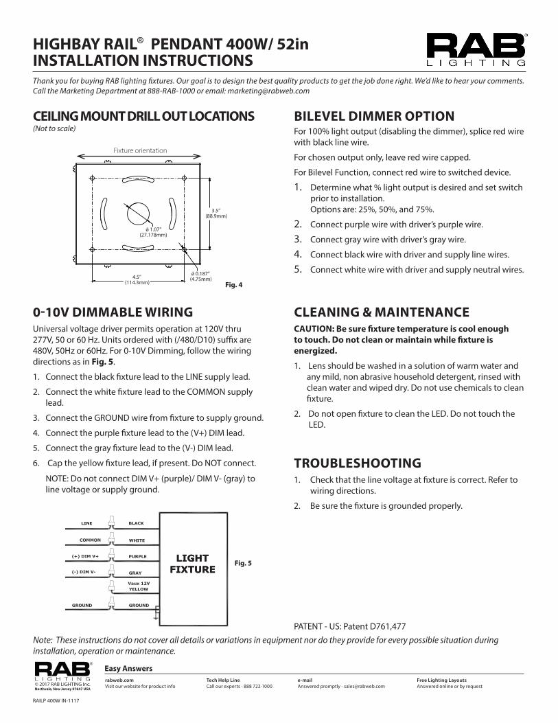
CEILING MOUNT DRILL OUT LOCATIONS (Not to scale)
Fig. 4
3.5” (88.9mm)
ǿ 0.187” (4.75mm)
ǿ 1.07” (27.178mm)
4.5” (114.3mm)
Fixture orientation
HIGHBAY RAIL 400WEMERGENCY BATTERY BACKUP INSTRUCTIONSThank you for buying RAB lighting fixtures. Our goal is to design the best quality products to get the job done right. We’d like to hear your comments. Call the Marketing Department at 888-RAB-1000 or email: [email protected]
®
AA
B B
C C
D D
4
1234
23
R A B
IMPORTANTREAD CAREFULLY BEFORE INSTALLING FIXTURE. RETAIN THESE INSTRUCTIONS FOR FUTURE REFERENCE.
Fixtures must be wired in accordance with the National Electrical Code and all applicable local codes. Proper grounding is required for safety. THIS PRODUCT MUST BE INSTALLED IN ACCORDANCE WITH THE APPLICABLE INSTALLATION CODE BY A PERSON FAMILIAR WITH THE CONSTRUCTION AND OPERATION OF THE PRODUCT AND THE HAZARDS INVOLVED.
WARNING: Make certain power is OFF before installing or maintaining fixture. No user serviceable parts inside.
MOUNTING FIXTURE TO CEILINGMount Housing to sturdy ceiling structure as follows:FOR V HOOK MOUNTING1. V Hooks (4) are provided for chain mounting. Secure V Hooks
through mounting hole at back of Housing as in Fig. 1. 2. Connect to four (4) equal lengths of chain (by others) and/or
appropriate hardware (by others) suitable for mounting surface, to suspend Housing from V Hooks.
3. Fixture mounting height and spacing should be determined by application requirements. Use chain suitable to support four (4) times the weight of the fixture.
4. Remove one of the Access Plate and feed supply wire with strain relief conduit connector through Access Plate and make electrical connections as shown in wiring diagram. Use approved wiring connectors and wire to local NEC codes. Push all wires back into Housing. Be careful not to pinch wires.
5. Tighten screws (2) and secure Access Plate.
Fig. 1
V Hook (4)
Access Plate
Housing
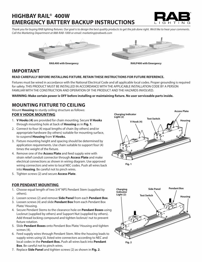
RAIL400 with Emergency
Charging Indicator Light (2)
Test Switch
RAILP400 with Emergency
FOR PENDANT MOUNTING 1. Choose equal length of two 3/4” NPS Pendant Stem (supplied by
others).2. Loosen screws (2) and remove Side Panel from each Pendant Box.3. Loosen screws (4) and slide Pendant Box from each Pendant Box
Plate/ Housing.4. Secure Pendant Stems to the clearance hole on Pendant Boxes using
Locknut (supplied by others) and Support Nut (supplied by others). Add thread locking compound and tighten locknut/ nut to prevent fixture rotation.
5. Slide Pendant Boxes onto Pendant Box Plate/ Housing and tighten screws (4).
6. Feed supply wires through Pendant Stem. Wire the housing leads to supply wires using UL listed wire connectors according to NEC and local codes in the Pendant Box. Push all wires back into Pendant Box. Be careful not to pinch wires.
7. Replace Side Panel and tighten screws (2) as shown in Fig. 2.
Fig. 2
AA
B B
C C
D D
4
1234
23
R A B L I G H T I N G 170 LUDLOW AVE., NORTHVALE, NJ 07647
THIS DRAWING AND THE INFORMATION IT DISCLOSES IS THE EXCLUSIVE
PROPERTY OF RAB LIGHTING, INCORPORATEDANY REPRODUCTION OR USE OF THIS DRAWING WITHOUT THE WRITTEN CONSENT OFRAB LIGHTING, INC. IS STRICTLY PROHIBITED. RAB CONFIDENTIAL PATENT PENDING
ECN # REV DESCRIPTION DATE Init.1
TOLERANCES.X .02
.XX .01.XXX .005
ANGLES .5
Pendant BoxSide Panel
HousingTest Switch
Charging Indicator Light (2)
HIGHBAY RAIL 400WEMERGENCY BATTERY BACKUP INSTRUCTIONSThank you for buying RAB lighting fixtures. Our goal is to design the best quality products to get the job done right. We’d like to hear your comments. Call the Marketing Department at 888-RAB-1000 or email: [email protected]
®
FOR SURFACE MOUNTING 1. Loosen screws (2) and remove Side Panel from each Pendant
Box.2. Loosen screws (4) and slide Pendant Box from each Pendant
Box Plate/ Housing.3. Mount each Pendant Box to ceiling by drilling out Drill Out
Locations as shown on Fig. 3. Use appropriate mounting hardware suitable for the mounting surface.
4. Slide Pendant Boxes onto Pendant Box Plate/ Housing and tighten Screws (4).
5. Wire the housing leads to supply wires using UL listed wire connectors according to NEC and local codes in one of the Pendant Box. Push all wires back into Pendant Box. Be careful not to pinch wires.
6. Replace the Side Panel and tighten screws (2) as shown in Fig. 2.
Note: These instructions do not cover all details or variations in equipment nor do they provide for every possible situation during installation operation or maintenance.
To reduce the risk of electric shock, disconnect both normal and emergency power supplies and converter connector of the emergency ballast before servicing. Do not attempt to service the emergency ballast. The use of accessory equipment may cause an unsafe condition. Do not use this product for other than intended use. Refer any servicing indicated by these checks to a Qualified Service Personnel.
TROUBLESHOOTING 1. Check that the line voltage at fixture is correct. Refer
to wiring directions.
2. Be sure the fixture is grounded properly.
CLEANING CAUTION: Be sure fixture temperature is cool enough to touch. Do not clean or maintain while fixture is energized.1. Lens should be washed in a solution of warm water and any
mild, non abrasive household detergent, rinsed with clean water and wiped dry. Do not use chemicals to clean fixture.
2. Do not open fixture to clean the LED. Do not touch the LED.
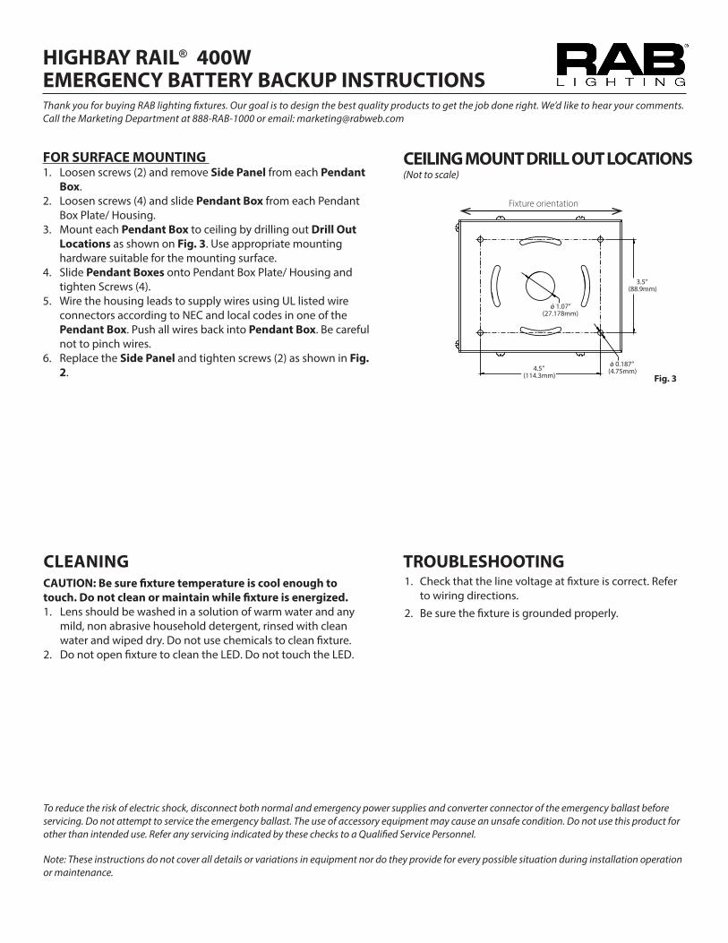
CEILING MOUNT DRILL OUT LOCATIONS (Not to scale)
Fig. 3
3.5” (88.9mm)
ǿ 0.187” (4.75mm)
ǿ 1.07” (27.178mm)
4.5” (114.3mm)
Fixture orientation
HIGHBAY RAIL 400WEMERGENCY BATTERY BACKUP INSTRUCTIONSThank you for buying RAB lighting fixtures. Our goal is to design the best quality products to get the job done right. We’d like to hear your comments. Call the Marketing Department at 888-RAB-1000 or email: [email protected]
®
WIRING CAUTION: THIS IS AN EMERGENCY BATTERY BACKUP FIXTURE. Voltage could be present in Battery. To prevent high voltage from being present on output leads, inverter connector must be open. Do not join inverter connector until installation is complete and AC power is supplied to the emergency ballast. NOTE: Make sure that the necessary branch circuit wiring is available. An unswitched AC source of power is required. The emergency ballast must be fed from the same branch circuit as the AC ballast.Do not use any supply voltage other than those specified below. RAILxx/E2 120V-277V, 50/ 60Hz1. Connect the UNSWITCHED black fixture lead to the HOT supply
lead.2. Connect red and black lead together, if not using a switching
method.3. If switching, connect SWITCHED red lead to a switch.4. Connect the COMMON fixture lead to the COMMON supply
lead.5. For 0-10V Dimming, connect DIM (+) purple lead and DIM (-)
gray lead to 0-10V dimmer. Do not connect the yellow lead, if present. NOTE: Do not connect DIM V+ (purple)/ DIM V- (gray) to line voltage or supply ground.
6. Connect the GROUND wire from fixture to supply ground. 7. All unused leads must be capped and insulated.8 After installation is complete, supply AC power to the
emergency ballast and join the inverter connector.9. At this point, power should be connected to both the AC
ballast and the emergency ballast, and the Charging Indicator Light (2) as shown in Fig. 1 should illuminate indicating the battery is charging.
10. A short-term discharge test may be conducted after the emergency ballast has been charging for one hour. Charge for 24 hours before conducting a long-term discharge test. Refer to OPERATION.
OPERATION1. When AC power is applied, the Charging Indicator
Light (2) as shown in Fig. 1 and Fig. 2 is illuminated, indicating that the battery is being charged.
2. When power fails, the emergency ballast automatically switches to emergency power (internal battery), operating at reduced illumination. The emergency ballast supplies 2x25W of power (output power) at a maximum connected load of 2x0.60A at a rated voltage of 36-42VDC in emergency mode for a minimum of 90 minutes.
3. When AC power is restored, the emergency ballast automatically returns to charging mode.
Easy Answersrabweb.comVisit our website for product info
MAINTENANCE Although no routine maintenance is required to keep the emergency ballast functional, it should be checked periodically to ensure that it is working. The following schedule is recommended:1. Visually inspect the charging indicator lights monthly.
It should be illuminated.2. Test the emergency operation of the fixture at 30-day
intervals for a minimum of 30 seconds. 3. Conduct a 90-minute discharge test once a year.
Fixture would operate at reduced illumination for a minimum of 90 minutes.
PATENT - US: Patent D761,477
Black/Unswitched Line 120-277V
IF U
NS
WIT
CH
ED,
CA
P T
WO
BLA
CK
WIR
ES A
ND
TW
OW
HIT
E W
IRES
TOG
ETH
ER
Black/Switched Line 120-277V
LEA
VE O
PEN
DO
NO
T C
ON
NEC
TD
UR
ING
MA
NU
FAC
TUR
ING
CU
STO
MER
SH
OU
LDC
ON
NEC
T O
NLY
AFT
ER F
INIS
HIN
GW
IRIN
G T
O A
CPO
WER
. B
ATT
ERY
CO
ULD
HA
VEC
HA
RG
E &
SH
OC
K
Green/Ground
EUC-096S245DT/
RDD-096-A2450
EUC-096S245DT/
RDD-096-A2450
EUC-096S245DT/
RDD-096-A2450
LEA
VE O
PEN
DO
NO
T C
ON
NEC
TD
UR
ING
MA
NU
FAC
TUR
ING
CU
STO
MER
SH
OU
LDC
ON
NEC
T O
NLY
AFT
ER F
INIS
HIN
GW
IRIN
G T
O A
CPO
WER
. B
ATT
ERY
CO
ULD
HA
VEC
HA
RG
E &
SH
OC
K
EUC-096S245DT/
RDD-096-A2450
White/Common 120-277V
RAIL
400
EM IN
111
7
DRI
VER
WIR
ING
DIA
GRA
M fo
r RA
IL 4
00W
EM
ERG
ENCY
OPE
RATI
ON
Em
erge
ncy
Balla
st a
nd A
C D
river
mus
t be
fed
from
the
sam
e ci
rcui
t
400
DRI
VER
DRI
VER
DRI
VER
HIGHBAY RAIL 400WEMERGENCY BATTERY BACKUP INSTRUCTIONSThank you for buying RAB lighting fixtures. Our goal is to design the best quality products to get the job done right. We’d like to hear your comments. Call the Marketing Department at 888-RAB-1000 or email: [email protected]
®
AA
B B
C C
D D
4
1234
23
R A B
IMPORTANTREAD CAREFULLY BEFORE INSTALLING FIXTURE. RETAIN THESE INSTRUCTIONS FOR FUTURE REFERENCE.
Fixtures must be wired in accordance with the National Electrical Code and all applicable local codes. Proper grounding is required for safety. THIS PRODUCT MUST BE INSTALLED IN ACCORDANCE WITH THE APPLICABLE INSTALLATION CODE BY A PERSON FAMILIAR WITH THE CONSTRUCTION AND OPERATION OF THE PRODUCT AND THE HAZARDS INVOLVED.
WARNING: Make certain power is OFF before installing or maintaining fixture. No user serviceable parts inside.
MOUNTING FIXTURE TO CEILINGMount Housing to sturdy ceiling structure as follows:FOR V HOOK MOUNTING1. V Hooks (4) are provided for chain mounting. Secure V Hooks
through mounting hole at back of Housing as in Fig. 1. 2. Connect to four (4) equal lengths of chain (by others) and/or
appropriate hardware (by others) suitable for mounting surface, to suspend Housing from V Hooks.
3. Fixture mounting height and spacing should be determined by application requirements. Use chain suitable to support four (4) times the weight of the fixture.
4. Remove one of the Access Plate and feed supply wire with strain relief conduit connector through Access Plate and make electrical connections as shown in wiring diagram. Use approved wiring connectors and wire to local NEC codes. Push all wires back into Housing. Be careful not to pinch wires.
5. Tighten screws (2) and secure Access Plate.
Fig. 1
V Hook (4)
Access Plate
Housing
RAIL400 with Emergency
Charging Indicator Light (2)
Test Switch
RAILP400 with Emergency
FOR PENDANT MOUNTING 1. Choose equal length of two 3/4” NPS Pendant Stem (supplied by
others).2. Loosen screws (2) and remove Side Panel from each Pendant Box.3. Loosen screws (4) and slide Pendant Box from each Pendant Box
Plate/ Housing.4. Secure Pendant Stems to the clearance hole on Pendant Boxes using
Locknut (supplied by others) and Support Nut (supplied by others). Add thread locking compound and tighten locknut/ nut to prevent fixture rotation.
5. Slide Pendant Boxes onto Pendant Box Plate/ Housing and tighten screws (4).
6. Feed supply wires through Pendant Stem. Wire the housing leads to supply wires using UL listed wire connectors according to NEC and local codes in the Pendant Box. Push all wires back into Pendant Box. Be careful not to pinch wires.
7. Replace Side Panel and tighten screws (2) as shown in Fig. 2.
Fig. 2
AA
B B
C C
D D
4
1234
23
R A B L I G H T I N G 170 LUDLOW AVE., NORTHVALE, NJ 07647
THIS DRAWING AND THE INFORMATION IT DISCLOSES IS THE EXCLUSIVE
PROPERTY OF RAB LIGHTING, INCORPORATEDANY REPRODUCTION OR USE OF THIS DRAWING WITHOUT THE WRITTEN CONSENT OFRAB LIGHTING, INC. IS STRICTLY PROHIBITED. RAB CONFIDENTIAL PATENT PENDING
ECN # REV DESCRIPTION DATE Init.1
TOLERANCES.X .02
.XX .01.XXX .005
ANGLES .5
Pendant BoxSide Panel
HousingTest Switch
Charging Indicator Light (2)
HIGHBAY RAIL 400WEMERGENCY BATTERY BACKUP INSTRUCTIONSThank you for buying RAB lighting fixtures. Our goal is to design the best quality products to get the job done right. We’d like to hear your comments. Call the Marketing Department at 888-RAB-1000 or email: [email protected]
®
FOR SURFACE MOUNTING 1. Loosen screws (2) and remove Side Panel from each Pendant
Box.2. Loosen screws (4) and slide Pendant Box from each Pendant
Box Plate/ Housing.3. Mount each Pendant Box to ceiling by drilling out Drill Out
Locations as shown on Fig. 3. Use appropriate mounting hardware suitable for the mounting surface.
4. Slide Pendant Boxes onto Pendant Box Plate/ Housing and tighten Screws (4).
5. Wire the housing leads to supply wires using UL listed wire connectors according to NEC and local codes in one of the Pendant Box. Push all wires back into Pendant Box. Be careful not to pinch wires.
6. Replace the Side Panel and tighten screws (2) as shown in Fig. 2.
Note: These instructions do not cover all details or variations in equipment nor do they provide for every possible situation during installation operation or maintenance.
To reduce the risk of electric shock, disconnect both normal and emergency power supplies and converter connector of the emergency ballast before servicing. Do not attempt to service the emergency ballast. The use of accessory equipment may cause an unsafe condition. Do not use this product for other than intended use. Refer any servicing indicated by these checks to a Qualified Service Personnel.
TROUBLESHOOTING 1. Check that the line voltage at fixture is correct. Refer
to wiring directions.
2. Be sure the fixture is grounded properly.
CLEANING CAUTION: Be sure fixture temperature is cool enough to touch. Do not clean or maintain while fixture is energized.1. Lens should be washed in a solution of warm water and any
mild, non abrasive household detergent, rinsed with clean water and wiped dry. Do not use chemicals to clean fixture.
2. Do not open fixture to clean the LED. Do not touch the LED.
CEILING MOUNT DRILL OUT LOCATIONS (Not to scale)
Fig. 3
3.5” (88.9mm)
ǿ 0.187” (4.75mm)
ǿ 1.07” (27.178mm)
4.5” (114.3mm)
Fixture orientation
HIGHBAY RAIL 400WEMERGENCY BATTERY BACKUP INSTRUCTIONSThank you for buying RAB lighting fixtures. Our goal is to design the best quality products to get the job done right. We’d like to hear your comments. Call the Marketing Department at 888-RAB-1000 or email: [email protected]
®
WIRING CAUTION: THIS IS AN EMERGENCY BATTERY BACKUP FIXTURE. Voltage could be present in Battery. To prevent high voltage from being present on output leads, inverter connector must be open. Do not join inverter connector until installation is complete and AC power is supplied to the emergency ballast. NOTE: Make sure that the necessary branch circuit wiring is available. An unswitched AC source of power is required. The emergency ballast must be fed from the same branch circuit as the AC ballast.Do not use any supply voltage other than those specified below. RAILxx/E2 120V-277V, 50/ 60Hz1. Connect the UNSWITCHED black fixture lead to the HOT supply
lead.2. Connect red and black lead together, if not using a switching
method.3. If switching, connect SWITCHED red lead to a switch.4. Connect the COMMON fixture lead to the COMMON supply
lead.5. For 0-10V Dimming, connect DIM (+) purple lead and DIM (-)
gray lead to 0-10V dimmer. Do not connect the yellow lead, if present. NOTE: Do not connect DIM V+ (purple)/ DIM V- (gray) to line voltage or supply ground.
6. Connect the GROUND wire from fixture to supply ground. 7. All unused leads must be capped and insulated.8 After installation is complete, supply AC power to the
emergency ballast and join the inverter connector.9. At this point, power should be connected to both the AC
ballast and the emergency ballast, and the Charging Indicator Light (2) as shown in Fig. 1 should illuminate indicating the battery is charging.
10. A short-term discharge test may be conducted after the emergency ballast has been charging for one hour. Charge for 24 hours before conducting a long-term discharge test. Refer to OPERATION.
OPERATION1. When AC power is applied, the Charging Indicator
Light (2) as shown in Fig. 1 and Fig. 2 is illuminated, indicating that the battery is being charged.
2. When power fails, the emergency ballast automatically switches to emergency power (internal battery), operating at reduced illumination. The emergency ballast supplies 2x25W of power (output power) at a maximum connected load of 2x0.60A at a rated voltage of 36-42VDC in emergency mode for a minimum of 90 minutes.
3. When AC power is restored, the emergency ballast automatically returns to charging mode.
Easy Answersrabweb.comVisit our website for product info
MAINTENANCE Although no routine maintenance is required to keep the emergency ballast functional, it should be checked periodically to ensure that it is working. The following schedule is recommended:1. Visually inspect the charging indicator lights monthly.
It should be illuminated.2. Test the emergency operation of the fixture at 30-day
intervals for a minimum of 30 seconds. 3. Conduct a 90-minute discharge test once a year.
Fixture would operate at reduced illumination for a minimum of 90 minutes.