1 NOVEMBER 2011 TS TIDINGS TECHNICAL SERVICES / PSSR VIJAYAWADA TPP NOVEMBER: 2011 VOLUME: 15.06 Published by Technical Services / PSSR For internal circulation HIGHLIGHTS BELLARY 500 MW UNIT 2: SECOND STAGE STEAM BLOWING WAS COMPLETED. TG LUBE OIL FLUSHING WAS COMPLETED CPCL PHASE 3 - UNIT 4: CRANKING OPERATION WAS SUCCESSFULLY DONE. HRSG AIR LEAK TEST WAS COMPLETED SUCCESSFULLY AND PROTOCOL WAS SIGNED BY THE CUSTOMER. VALLUR 3 X 500 MW, UNIT 1: FIRST STAGE STEAM BLOWING WAS STARTED.
Transcript
1 NOVEMBER 2011 TS TIDINGS
TECHNICAL SERVICES / PSSR
VIJAYAWADA TPP NOVEMBER: 2011 VOLUME: 15.06
Published by Technical Services / PSSR For internal circulation
HIGHLIGHTS
BELLARY 500 MW UNIT 2:
SECOND STAGE STEAM BLOWING WAS COMPLETED.
TG LUBE OIL FLUSHING WAS COMPLETED
CPCL PHASE 3 - UNIT 4:
CRANKING OPERATION WAS SUCCESSFULLY DONE.
HRSG AIR LEAK TEST WAS COMPLETED SUCCESSFULLY AND PROTOCOL WAS SIGNED BY THE CUSTOMER.
VALLUR 3 X 500 MW, UNIT 1:
FIRST STAGE STEAM BLOWING WAS STARTED.
2 NOVEMBER 2011 TS TIDINGS
TECHNICAL SERVICES / PSSR
INSIDE
1. STATUS OF PROJECTS COMMISSIONED / TO BE COMMISSIONED DURING 2010 - 2012.
2. SERVICE RENDERED TO OTHER REGIONS/SAS/PROJECTS AFTER CONTRACT
CLOSING/CUSTOMER TRAINING.
3. APPRECIATION FROM CUSTOMER FOR SERVICES RENDERED.
4. FEED BACK ON EQUIPMENTS FROM SITES.
5. LET US KNOW. SUPERVISORY CONTROL AND DATA ACQUISITION
Feed backs and suggestions from all departments of BHEL for improvement of TS TIDINGS are welcome and may please be addressed to ADDL. GENERAL MANAGER (TSX)/BHEL-PSSR/CHENNAI
3 NOVEMBER 2011 TS TIDINGS
TECHNICAL SERVICES / PSSR
STATUS OF PROJECTS COMMISSIONED / TO BE COMMISSIONED DURING 2010 – 2012: BELLARY 500 MW UNIT 2:
Boiler was lighted up on 01.11.11 for second stage steam blowing and second stage steam blowing was completed on 09.11.2011.
Mill – A, C & D motor trial run and Mill – A & B no load trial run was completed.
TG DMCW-C pump trial run was completed.
ESP – D pass LTMSB scheme checking was completed and demonstrated to customer.
Clarifier water MCC transformer - 2 was charged.
Flushing of hot well make up line and deaerator make up line was completed.
Ash handling system MCC – CT & PT and relay testing was completed.
ACW pump –A was run and flushing up to self cleaning strainer was carried out.
Seal oil pump motor trial run was completed.
Generator PW system – Cold water flushing with magnetic filter was declared completed.
GT R and Y phase oil filtration was in progress.
LP heaters drip line steam flushing was completed.
RODM plant: 2 nos. chemical cleaning pumps motor trial run was carried out.
TG LUBE OIL FLUSHING WAS COMPLETED ON 18.11.11.
Turbine lube oil system and seal oil system hydro test was carried out.
Control fluid flushing was in progress.
Turbine vacuum pump-A & B motor trial run was completed.
Furnace first and second pass gas tightness test was completed.
Mill – C stage – II flushing was declared completed
4 NOVEMBER 2011 TS TIDINGS
TECHNICAL SERVICES / PSSR
CW Pump D motor trial run was completed after balancing. CW Pump B trial run was completed.
ACW pump – C trial run was completed.
Ash handling system – MCC was charged and 2 nos. slurry water pump motor trial run was carried out.
AC and DC JOP trial run was completed.
Jacking oil system hydro test (at 200 Kg) was completed.
Generator Transformer – B phase HT bushing tan delta test was completed.
Boiler Outlet Flange (BOF) to ESP air tightness test upto 285 mmwc was carried out.
CPCL PHASE 3 - UNIT 4:
Inlet air filter installation was completed.
Bentley Nevada – VMS system was charged and cards were configured. Vibration probes calibration was completed.
Honey well PLC computer was charged and communication was established between Computer and Controller.
Guillotine damper – Electrical commissioning was completed.
GT was put on ratcheting on 15.11.11 for four hours.
CRANKING OPERATION WAS SUCCESSFULLY DONE ON 18.11.11 AND ALL PARAMETERS WERE FOUND TO BE NORMAL.
HRSG AIR LEAK TEST WAS COMPLETED SUCCESSFULLY ON 21.11.11 AND PROTOCOL WAS SIGNED BY THE CUSTOMER.
Cooling water line passivation was completed.
6.6 KV HT switchgear bus A& B was charged.
Generator oil filtration started and was in progress.
5 NOVEMBER 2011 TS TIDINGS
TECHNICAL SERVICES / PSSR
KOTHAGUDAM 500 MW, UNIT 1:
TDBFP – A oil filling, Solo run was completed and over speed test was carried out after attending the thrust bearing failure
Unit tripped on 09.11.11 due to local emergency push button pressing of generator PW pump. Unit was synchronized on 14.11.11 and loaded to 280 MW.
TDBFP – B turbine was rolled to 3000 rpm after attending the super heater spray flange leak and erosion of flange
Unit is presently running around full load.
NALCO – 120 MW UNIT 10:
Unit was running around 110 MW till 18.11.11.
Unit was shut down on 19.11.11 due to Boiler tube leakage.
Unit was synchronized on 29.11.11 and presently unit is running around 90 MW.
SG PG test : BHEL/Trichy team and TG PG test team are at site for PG test preparatory works.
NEYVELI TS II EXP CFBC, 2 X 250 MW, UNIT 1:
CFBC was boxed up since 24.09.11 to attend to shut down jobs and rectification works.
Rotary air lock feeders – 4 hours trial run of A,B, C & D was completed after rectification work.
SCW 140 tubes in affected zone was completed.
Refractory area repair work was in progress. NEYVELI TS II EXP CFBC, 2 X 250 MW, UNIT 2:
BFP – 2B oil flushing is in progress.
6 NOVEMBER 2011 TS TIDINGS
TECHNICAL SERVICES / PSSR
TG control oil piping air blasting was completed.
6.6 KV interconnecting bus B (Unit 1 and 2) was charged.
LT panel 2DA and 2EA was charged.
AC EOP, AC JOP, AOP 1& 2 and DC EOP & DC JOP motor trial run was completed.
RINL:
TB – 4:
TG oil flushing was started on 08.10.11 and is in progress.
ESP HT breaker (11 KV) testing was completed.
DC EOP trial run was completed.
Ventilation system MCC testing was carried out.
220 V DC boarding testing was completed.
Remote commissioning of CW line actuators was completed.
Stage – II steam blowing of extraction line was completed.
Condenser hydro test was completed.
SG – 6:
FD fan Stage II lube oil flushing was completed.
ID fan – A and FD fan – A lube oil lines acid cleaning and hydro test was completed.
SIMHADRI STAGE II, 2 X 500 MW, UNIT 3:
TDBFP –A vibration problem was resolved by replacing the damaged gear coupling of booster pump side from unit 4.
Unit was running around 300 MW from 11.11.2011 up to 21.11.2011. Load reduction was due to non-availability of PA fan – B because of vibration problem.
Vibration problem was resolved by BHEL/Ranipet. Unit is presently running at full load.
7 NOVEMBER 2011 TS TIDINGS
TECHNICAL SERVICES / PSSR
SIMHADRI STAGE II, 2 X 500 MW, UNIT 4:
ESP – D pas air leak test was carried out on 09.11.11 at 22 mmwc. ID fan – B and FD fan – B stage II lube oil flushing was declared completed. SAPH -4A Guide and support bearing lube oil flushing was started and is in
progress. SAPH- 4B – trial run with main motor and air motor was completed. LT PRDS line steam blowing was completed. Service air line flushing upto air motor of SAPH-B was done. Atomising line steam blowing of all corner stations at all elevations was
completed. FD fan – B trial run was carried out. Second instrument air compressor trial run was completed. LDO line air leak test was carried out from unit 3 to unit 4 up to AB
elevation. Cooling water line for ID fan –B, FD fan – B and PA fan- B was flushed. Duct leak test was conducted up to APH inlet by running FD fan – B.
VALLUR 3 X 500 MW, UNIT 1:
Commissioning of 30% feed control vale, MDBFP discharge valve and economizer inlet valve was completed.
CC pump – B trial run was carried out. TG AOP – A motor trial run was completed. Hydro test of boiler drum, SH and MS line was carried out at 100 Kg. FIRST STAGE STEAM BLOWING WAS STARTED ON 05.11.11 AND
COMPLETED ON 10.11.11. TG MOT oil filling was completed and TG Lube oil flushing was started on
09.11.2011. Reheater lines hydro test was completed in the presence of Boiler Inspector. Second stage steam blowing was completed on 28.11.11. Steam blowing of auxiliary lines (CRH to PRDS, MS to PRDS, CRH to HP heater)
was completed. Steam blowing of CRH to TDBFP, PRDS to TDBFP, Extraction line to TDBFP,
station PRDS ( HT & LT ) and extraction to deaerator line was completed.
8 NOVEMBER 2011 TS TIDINGS
TECHNICAL SERVICES / PSSR
KAKATIYA 500 MW - UNIT 1 :
Beach nut & HP inlet insert received from BHEL/Hardwar on 30.11.11 and blue matching with HP out casing is in progress.
SERVICES RENDERED TO CUSTOMER /SAS/MUs:
--- NIL ---
CUSTOMER TRAINING & TECHNICAL PAPER PRESENTED:
--- NIL ---
APPRECIATION FROM CUSTOMER FOR SERVICES RENDERED :
--- NIL ---
9 NOVEMBER 2011 TS TIDINGS
TECHNICAL SERVICES / PSSR
FEED BACK NO.1
PROJECT: KOTHAGUDEM TPS STAGE VI , UNIT – 11 (1 X 500MW)
PROBLEM: UNIT TRIPPING ON 87OA DIFFERENTIAL PROTECTION
Kothagudem TPS Stage VI 1 X 500MW unit is running at around 300MW load till 24/09/2011 and got tripped on 87OA differential protection. The overall differential protection serves a backup protection for 87GT,87UT and 87HV , and has protection range covering Generator, Unit Transformer, Generator Transformer along with the over head line till the 400KV breaker in the Switch Yard. During the initial tripping of 87OA on 24/09/11 we have checked the Generator and Generator Transformer IR values to ensure that everything is fine with the equipment and found normal. During the initial tripping of 87OA on 24/09/11 we have checked the Generator and Generator Transformer IR values to ensure that everything is fine with the equipment and found normal. We have the checked the CT wiring from Switchyard CTs and Generator CTs for any loose contacts and found no problem. Along with the 87OA differential protection, HV standby earth fault also picked up in the relay which shows an earth fault occurred on the HV side of the Generator Transformer. Upon enquiry with the PGCIL LDC near Khammam, there is fault in the line side of the 400KV switchyard 19KM away from the generating station and the fault is pretty severe. The reports were attached along with this document. So, as the fault is severe we have thought of CT saturation might be the case for operation of differential protection and got confirmed the same from PEM. So we have gone ahead with the synchronization of the unit.
10 NOVEMBER 2011 TS TIDINGS
TECHNICAL SERVICES / PSSR
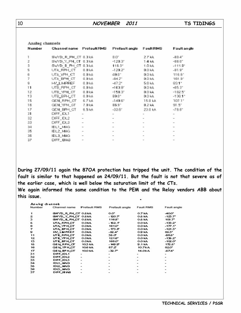
During 27/09/11 again the 87OA protection has tripped the unit. The condition of the fault is similar to that happened on 24/09/11. But the fault is not that severe as of the earlier case, which is well below the saturation limit of the CTs. We again informed the same condition to the PEM and the Relay vendors ABB about this issue.
11 NOVEMBER 2011 TS TIDINGS
TECHNICAL SERVICES / PSSR
The relay vendor has studied the situation with various disturbance reports site has sent from the relay and proposed a solution. The solution for the above problem is mentioned below. Proposed solution for operation of Differential Protection operation for External Earth Fault Actual Parameter settings in IED
12 NOVEMBER 2011 TS TIDINGS
TECHNICAL SERVICES / PSSR
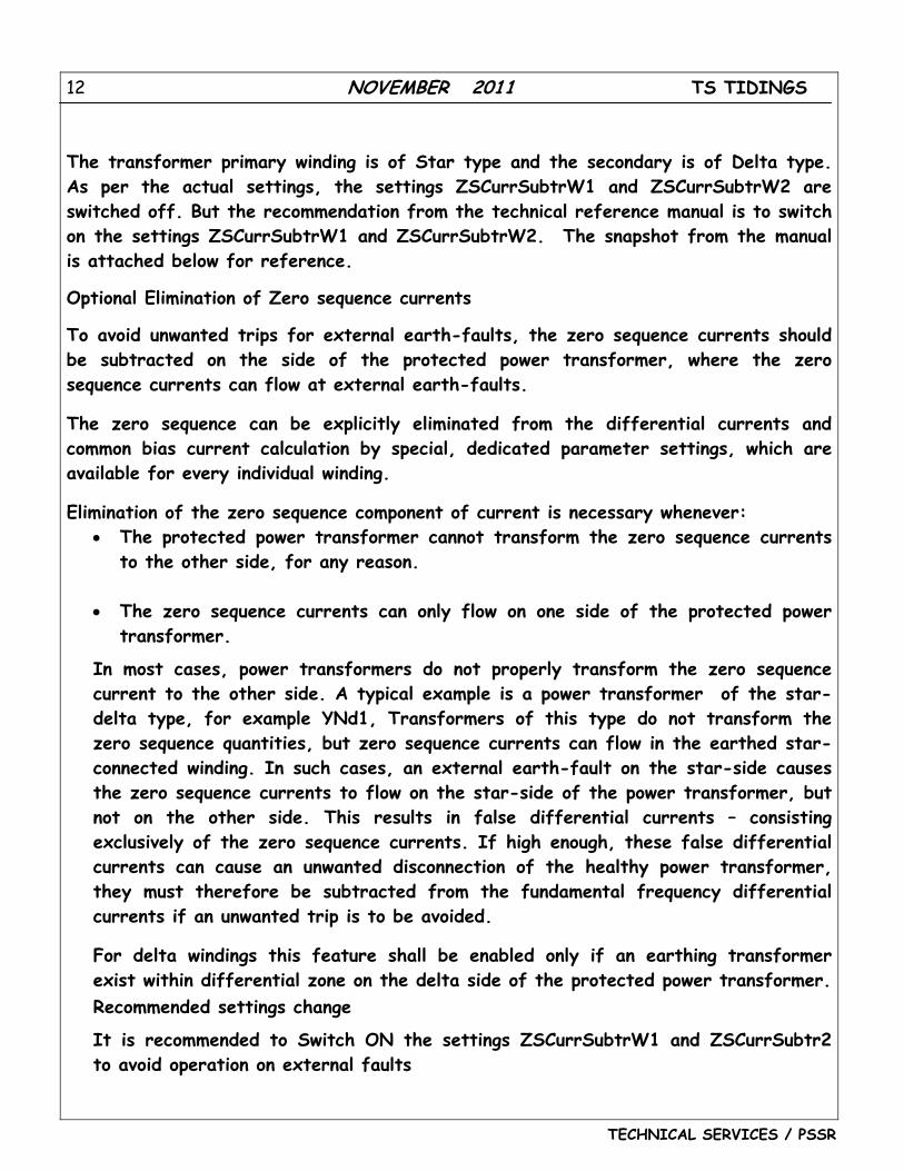
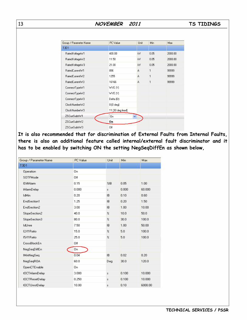
The transformer primary winding is of Star type and the secondary is of Delta type. As per the actual settings, the settings ZSCurrSubtrW1 and ZSCurrSubtrW2 are switched off. But the recommendation from the technical reference manual is to switch on the settings ZSCurrSubtrW1 and ZSCurrSubtrW2. The snapshot from the manual is attached below for reference.
Optional Elimination of Zero sequence currents
To avoid unwanted trips for external earth-faults, the zero sequence currents should be subtracted on the side of the protected power transformer, where the zero sequence currents can flow at external earth-faults.
The zero sequence can be explicitly eliminated from the differential currents and common bias current calculation by special, dedicated parameter settings, which are available for every individual winding.
Elimination of the zero sequence component of current is necessary whenever: • The protected power transformer cannot transform the zero sequence currents
to the other side, for any reason. • The zero sequence currents can only flow on one side of the protected power
transformer.
In most cases, power transformers do not properly transform the zero sequence current to the other side. A typical example is a power transformer of the star-delta type, for example YNd1, Transformers of this type do not transform the zero sequence quantities, but zero sequence currents can flow in the earthed star- connected winding. In such cases, an external earth-fault on the star-side causes the zero sequence currents to flow on the star-side of the power transformer, but not on the other side. This results in false differential currents – consisting exclusively of the zero sequence currents. If high enough, these false differential currents can cause an unwanted disconnection of the healthy power transformer, they must therefore be subtracted from the fundamental frequency differential currents if an unwanted trip is to be avoided.
For delta windings this feature shall be enabled only if an earthing transformer exist within differential zone on the delta side of the protected power transformer.
Recommended settings change
It is recommended to Switch ON the settings ZSCurrSubtrW1 and ZSCurrSubtr2 to avoid operation on external faults
13 NOVEMBER 2011 TS TIDINGS
TECHNICAL SERVICES / PSSR
It is also recommended that for discrimination of External Faults from Internal Faults, there is also an additional feature called internal/external fault discriminator and it has to be enabled by switching ON the setting NegSeqDiffEn as shown below,
14 NOVEMBER 2011 TS TIDINGS
TECHNICAL SERVICES / PSSR
Internal / external fault discriminator The internal/external fault discriminator is a very powerful and reliable supplementary criterion to the traditional differential protection. It is recommended that this feature shall be always used (that is, On) when protecting three-phase power transformers. The internal/external fault discriminator detects even minor faults, with a high sensitivity and at high speed, and at the same time discriminates with a high degree of dependability between internal and external faults. The internal/external fault discriminator responds to magnitudes and the relative phase angles of the negative-sequence fault currents at different windings (that is, sides) of the protected power transformer. The negative sequence fault currents must of course first be referred to the same phase reference side, and put to the same magnitude reference. This is done by the matrix expression (see equation 23).
Operation of the internal/external fault discriminator is based on the relative position of the two phasors representing winding one (W1) and winding two (W2) negative sequence current contributions, respectively, difined by expression shown in equation 23. It performs a directional comparison between these two phasors, First, the LV side phasor is reffered to the HV side (W1 side): both the magnitude, and the phase position are referred to the HV(W1 side): both the magnitude, and the phase position are referred to the HV (W1 side). Then the relative phase displacement between the two negative sequence current phasors is calculated. In case of three-winding power transformers, a little more complex algorithm is applied, with two directional tests. The overall directional characteristic of the internal/external fault discriminator is shown in figure 48, where the directional characteristic is defined by two setting parameters:
1. 1MinNegSeq 2. NegSeqROA
15 NOVEMBER 2011 TS TIDINGS
TECHNICAL SERVICES / PSSR
In order to perform directional comparison of the two phasors their magnitudes must be high enough so that one can be sure that they are due to a fault. On the other hand, in order to guarantee a good sensitivity of the internal/external fault discriminator, the value of this minimum limit must not be too high. Therefore this limit value, called 1minNegSeq, is settable in the range of 0.02 to 0.20 times the 1Base of the power transformer winding one. The default value is 0.04. Note that, in order to enhance stability at higher fault currents, the relatively very low threshold value IminNegSeq is dynamically increased at current, than 10% of the bias current is higher that 110% 1Base current, than 10% of the bias current is added to the 1minNegSeq. Only if magnitudes of both negative sequence current contributions are above the actual limit, the relative position between these two phasors is checked. If either of the negative sequence current contributions, which should be
16 NOVEMBER 2011 TS TIDINGS
TECHNICAL SERVICES / PSSR
campared, is too small (less than the set value for 1minNegSeq), no directional comparison is made in order to avoid the possibility to produce a wrong decision. This magnitude check, as well guarantee stability of the algorithm, when power transformer is energized. The setting NegSeqROA represents the so-called Relay Operate Angle, which determines the boundary between the internal and external fault regions. It can be selected in the range from ± 30 degrees to ± 120 degrees, with a step of 0.1 degree. The default value is ±60 degrees. The default setting ±60 degree favours somewhat security in comparison to dependability. If the above condition concerning magnitudes is fulfilled, the internal/external fault discriminator compares the relative phase angle between the negative sequence current contributions from the W1 and W2 sides of the power transformer using the following two rules :
• If the negative sequence currents contributions from W1 and W2 sides are in phase, the fault is internal (that is, both phasors are within protected zone)
• If the negative sequence currents contributions from W1 and W2 sides are 180
degrees out of phase, the fault is external (that is, W1 phasors is outside protected zone)
17 NOVEMBER 2011 TS TIDINGS
TECHNICAL SERVICES / PSSR
FEED BACK NO. 2
PROJECT: BELLARY UNIT -2 (500MW)
PROBLEM: CW PUMP VIBRATION
Bellary Unit# 2 CW pump motor was run on 14.11.2011, the vibration levels in the
motor non drive end was found very high. The matter was referred to BHEL/Bhopal and the motor was balanced and the vibration levels were reduced. The vibration readings are mentioned in the Table 1. During balancing totally 165 gm of weight was added in the holes 7 and 8 (81 gms on hole 7 and 84 gm in hole 8) which are provided in the motor NDE fan for balancing purpose.
CW Pump D Pump was started for first time on 28 th Nov 2011 and vibration levels of motor was found to be very high. The vibration readings are shown in Table 2. The matter was referred to BHEL/Hyderabad. BHEL/Hyderabad suggested for changing of the Impeller of CWP-D with the new one. After replacement of impeller, there was not much change in vibration level and it was decided to carryout insitu balancing of pump. During balancing 135 gms of weight was added in the hole no 6 The Vibration readings observed are enclosed in Annexure-I. The measured values are within the limits as per ISO 10816 Part-7. BHEL Hyderabad and Bhopal has given clearance to run the Pump on continuous operation CW Pump D was running continuously since 1130 hrs of 16/12/2011 pump is running smoothly all the parameters were found normal. The following are the vibration limits as per ISO 10816 Part-7, Zone B
Conclusion CW Pump motor alone was initially balanced and with coupled condition also balanced again. If any imbalance observed in the machine, machine shall be balanced for coupled condition.
18 NOVEMBER 2011 TS TIDINGS
TECHNICAL SERVICES / PSSR
Table 1: Vibration Reading of CW Pump D motor
Table 2: CW Pump D Vibration in coupled condition
Pump Discharge Pressure: 1.3 KSC (Disch .B/F Full open, RC valve full close) Motor current: 101 Amps
Location Radial Direction (Along Flow) (Disp. in microns /Vel in mm/sec)
Radial Direction (Across Flow) (Disp. in microns /Vel in mm/sec)
Axial Direction (Disp. in microns / Vel in mm/sec)
Motor DE 20/2.2 200/5.2 69/3.3 Motor NDE 393/8.8 680/16 76/2.7 Pump Brg Housing
--- 39/3.1 31/4.5
Table 3: CW Pump D vibration after new impeller replacement
Location
Along Flow Direction (Disp. in microns / Vel in mm/sec)
Across Flow (Disp. in microns / Vel in mm/sec)
Radial Axial Radial Axial
Motor DE 28/1 17/2.8 181/4.4 94/3.2 Motor NDE
255/6.6 25/2.2 623/15.1 --
Pump Brg Housing
-- -- 35/2.1 35/4.6
Test Condition Unit NDE DE H V A H V A
Disp in micron(pk-pk)
103 412 - 42 101 75 1.Before balancing
Decoupled. Vel mm/s(rms) - 11.6 - - - - Disp in micron(pk-
pk) 15 29 11 7 10 10
Vel mm/s(rms) 0.31 0.62 0.16 - -- -
2.After balancing Motor in
decoupled condition
Vel mm/s (pk) 1.7 1.7 1.4 1.4 1.5 1.5
19 NOVEMBER 2011 TS TIDINGS
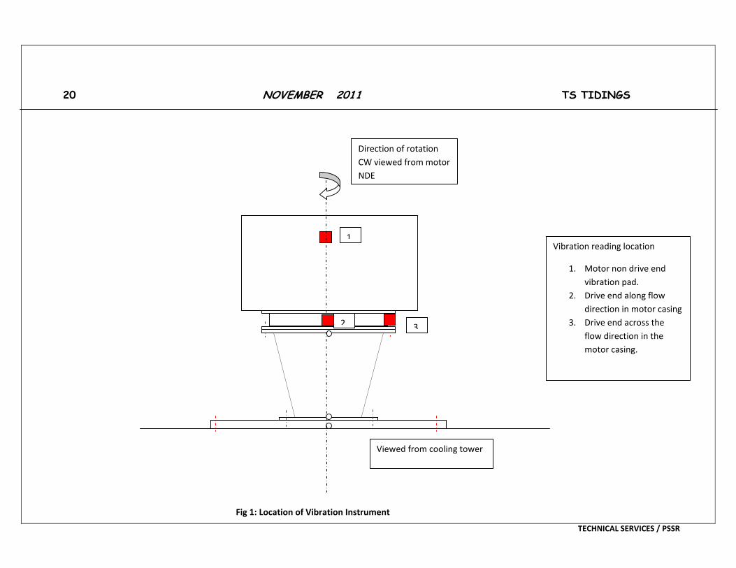
Motor Non Drive End Motor Drive End Thrust Bearing Housing
3. Drive end across the flow direction in the motor casing.
Viewed from cooling tower
Direction of rotation CW viewed from motor NDE
1
2 3
Fig 1: Location of Vibration Instrument
TECHNICAL SERVICES / PSSR
21 NOVEMBER 2011 TS TIDINGS
TECHNICAL SERVICES / PSSR
SUPERVISORY CONTROL AND DATA ACQUISITION
INTRODUCTION
SCADA, which stands for Supervisory Control and Data Acquisition, generally refers to the control system of the industry which is a computer system which controls and monitors a process. This process can be infrastructure, facility or industrial based which is as described as below:
Industrial processes include production, refining, manufacturing, fabrication, and power generation and may run in batch, continuous, discrete or repetitive modes.
The infrastructure processes can be private or public, and includes water treatment and the distribution, wastewater treatment and collection, electrical power distribution and transmission, gas and oil pipelines, civil defense siren systems, and the large communication systems.
Space stations, airports, ships, buildings both the private and public facilities have all the facility processes. These facility processes control and monitor access, consumption, HVAC, and energy
The following subsystems are usually present in the SCADA system:
The apparatus which presents to the human operator all the processed data and via this human operator control and monitor the processes is called Human-Machine Interface or HMI.
A supervisory system which acquires all the required data about the process and sending to the process all the control (commands).
Remote Terminal Units (RTUs) which connect to the sensors of the process, which help to convert the sensor signals to the digital data and sending this digital data to supervisory stream.
Programmable Logic Controller (PLCs) which are used like field devices rather than RTUs because PLCs are more versatile, configurable, economical, and flexible.
22 NOVEMBER 2011 TS TIDINGS
TECHNICAL SERVICES / PSSR
Communication infrastructure connects the Remote Terminal Units to supervisory system.
Several industries confuse over the differences between the Distributed control systems and SCADA systems. Generally SCADA system does not control the processes in real time but it usually refers to the system which coordinates the processes in real time. The discussion about the real time control becomes unclear due to the new telecommunications technology which helps in enabling high speed, reliability, and low latency communications over wide ranges. The differences between DCS and SCADA can be ignored as they are culturally determined. The differences between the DCS and SCADA will fade away as higher capacity communication infrastructures become available.
SCADA SYSTEMS CONCEPTS
SCADA refers to the centralized systems which control and monitor the entire sites, or they are the complexes of the systems which are spread out over large areas (between an industrial plant and country). Mostly all the control actions are automatically performed by the remote terminal units (RTUs) or by the programmable logic controllers (PLCs). The restrictions to the host control functions are supervisory level intervention or basic overriding. For example, the PLC in an industrial process controls the flow of cooling water, the SCADA system allows the operators for enabling the alarm conditions and for changing the set points for the flow, such as high temperature, loss of flow, to be recorded and displayed. The SCADA system keeps a tab on the total performance of the loop while the feedback control loop which passes from the PLC or the RTU.
Data acquisition starts at the PLC or RTU level which includes the equipment status reports and meter readings which are communicated as per requirement to the SCADA system. Data is then formatted and compiled in a way that by using the HMI
23 NOVEMBER 2011 TS TIDINGS
TECHNICAL SERVICES / PSSR
the operator of the control room can make the supervisory decisions to override or adjust normal PLC (RTU) controls. To allow the other analytical auditing and trending data can be fed to the Historian, which is built on a Database Management System commodity.
SCADA systems mostly implement the distributed database known as a tag database, containing data elements called points or tags. A point is a single output or input value which is controlled or monitored by the system. Points are either ‘soft’ or ‘hard’. The actual output or input of a system is represented by a hard point, whereas the soft point is due to the different math and logic operations which are applied to the other points. Mostly all the implementations are remove conceptually the distinctions by making all the properties a ‘soft’ point expression, which can, in the easiest case equate to a single a hard point. These points are usually stored as timestamp-value pairs: a value and the timestamp whenever it was calculated or recorded. Series of the timestamp-value pairs gives history of the particular point in consideration. Storing additional metadata with the tags is common, like the comments on the design time, alarm information, path to the field device or the PLC register.
Human Machine Interface
The HMI, or Human Machine Interface, is an apparatus that presents the processed data to the human operator and with which the process is controlled by the human operator.
To provide the SCADA systems the diagnostic data, management information and trending information such as logistic information, detailed schematics for a certain machine or sensor, maintenance procedures and troubleshooting guides for the expert system the HMI is linked to the SCADA system’s databases.
24 NOVEMBER 2011 TS TIDINGS
TECHNICAL SERVICES / PSSR
The information provided by the HMI to the operating personnel is generally graphical, in the form of mimic diagrams. This means the schematic representation of the plant which is being controlled is available to the operator. For example, the picture of the pump which is connected to the pipe shows to the operator that this pump is in running condition and the amount of fluid pumping through pipe at the particular moment. The pump can then be switched off by the operator. The software of the HMI shows the flow rate of fluid in pipe decrease in the real time. Mimic diagrams either consists of digital photographs of process equipment with animated symbols, or schematic symbols and line graphics to represent various process elements.
HMI package of the SCADA systems consist of a drawing program that the system maintenance personnel or operators use to change the representation of these points in the interface. These representations are simple like on-screen traffic light, that represents the state of the actual traffic light in field, or complex like the multi-projector display which represents the position of all the trains on railway or elevators in skyscraper.
One of the most important implementations of SCADA are alarms. The alarm has just two digital status points with values ALARM or NORMAL. When the requirements of the Alarm are met they are activated. For example, when the fuel tank is empty of a car, the alarm is activated and a light glows. The attention of the SCADA operator is drawn to the system which requires attention by the alarm. To alert the SCADA operators along with the managers text messages and emails are sent along with alarm activation.
SCADA HARDWARE
Solutions of the SCADA system many times have the components of the Distributed Control System. Execution of easy logic processes without having to involve the master computer is increasing day by day because of the use of ‘smart’ PLCs or RTUs.IEC61131-39(Ladder Logic) which is a functional block programming language, is often used in creating programs running on PLCs and RTUs. Due to resemblance of historic physical control arrays, IEC 61131-3 has very few training requirements, unlike procedural languages like FORTRAN and C programming language. Thus the system engineers of SCADA can perform implementation and design of programs being executed on PLC or RTU. The compact controller, Programmable automation controller (PAC), combines the capabilities and features of PC-based control system with any typical PLC. For providing PLC and RTU functions, PACs are
25 NOVEMBER 2011 TS TIDINGS
TECHNICAL SERVICES / PSSR
positions in the SCADA systems. ’Distributed RTUs’, in various electrical substation SCADA applications, use station computers or information processors for communicating with PACs, protective relays, and other I/O devices, and in return of traditional RTU, communicate with SCADA master.
Almost all big PLC manufacturers offered integrated HMI/SCADA systems, since 1998, many using non-proprietary and open communications protocols. Many skilled third party HMI/SCADA packages have stepped into the market, offering in-built compatibility with several major PLCs, which allow electrical engineers, mechanical engineers or technicians for configuring HMIs on their own, without requiring software-developer- written custom-made program.
REMOTE TERMINAL UNIT (RTU)
The RTU attaches to the physical equipment. Often, the RTU converts all electrical signals from equipment into digital values like the status- open/closed – from a valve or switch, or the measurements like flow, pressure, current or voltage. By converting as well as sending the electrical signals to the equipment, RTU may control equipment, like closing or opening a valve or a switch, or to set the speed of the pump.
SUPERVISORY STATION
‘Supervisory Station’ is used to refer to the software and servers responsible for communication with field equipment (PLCs, RTUs etc), and after that to HMI software which runs on the workstations in control room, or somewhere else. Master station could be composed of only one PC in small SCADA systems. Master station
26 NOVEMBER 2011 TS TIDINGS
TECHNICAL SERVICES / PSSR
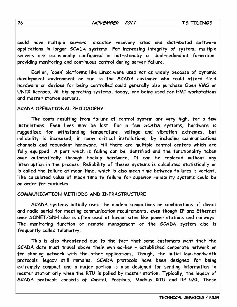
could have multiple servers, disaster recovery sites and distributed software applications in larger SCADA systems. For increasing integrity of system, multiple servers are occasionally configured in hot-standby or dual-redundant formation, providing monitoring and continuous control during server failure.
Earlier, ‘open’ platforms like Linux were used not as widely because of dynamic development environment or due to the SCADA customer who could afford field hardware or devices for being controlled could generally also purchase Open VMS or UNIX licenses. All big operating systems, today, are being used for HMI workstations and master station servers.
SCADA OPERATIONAL PHILOSOPHY
The costs resulting from failure of control system are very high, for a few installations. Even lives may be lost. For a few SCADA systems, hardware is ruggedized for withstanding temperature, voltage and vibration extremes, but reliability is increased, in many critical installations, by including communications channels and redundant hardware, till there are multiple control centers which are fully equipped. A part which is failing can be identified and the functionality taken over automatically through backup hardware. It can be replaced without any interruption in the process. Reliability of theses systems is calculated statistically or is called the failure at mean time, which is also mean time between failures ’s variant. The calculated value of mean time to failure for superior reliability systems could be on order for centuries.
COMMUNICATION METHODS AND INFRASTRUCTURE
SCADA systems initially used the modem connections or combinations of direct and radio serial for meeting communication requirements, even though IP and Ethernet over SONET/SDH also is often used at larger sites like power stations and railways. The monitoring function or remote management of the SCADA system also is frequently called telemetry.
This is also threatened due to the fact that some customers want that the SCADA data must travel above their own earlier – established corporate network or for sharing network with the other applications. Though, the initial low-bandwidth protocols’ legacy still remains. SCADA protocols have been designed for being extremely compact and a major portion is also designed for sending information to master station only when the RTU is polled by master station. Typically, the legacy of SCADA protocols consists of Conitel, Profibus, Modbus RTU and RP-570. These
27 NOVEMBER 2011 TS TIDINGS
TECHNICAL SERVICES / PSSR
protocols of communication are specifically SCADA-vendor but they are popularly used and adopted. Standard protocols mainly are IEC 61850, DNP3 and IEC 60870-5-101 or 104. These protocols of communication are recognized and standardized by all big SCADA vendors. Several of these protocols contain extensions for operating over the TCP/IP. It is considered good practice of security engineering for avoiding the SCADA systems from connecting to Internet for reducing attack surface.
Even before the advent of wide industry standards for the interoperability the development of many automatic controller devices and RTUs had started. Due to this creation of multitude of control protocols by the developers and its management. In order to ‘lock in’ their own customer base amongst the many vendors an incentive was there to create own protocols. Compilation of automation protocols is given here.
For the better intercommunication between the different software and hardware PLE for Process Control (OPC) is a widely accepted solution, which then even allows communication between the devices which were originally not even intended to be part of the industrial network.
SCADA ARCHITECTURES
The evolution of SCADA system has been through 3 generations as given below:
Monolithic: First Generation
Computing in the first generation was done with the help of Mainframe systems. When the SCADA was developed networks did not exist. Therefore the SCADA systems were without any connectivity to any other system hence were independent systems. Later on RTU vendors designed the Wide Area Networks which helped in communication with RTU. The usage of communication protocols at that time was proprietary. If the main mainframe system failed a back-up mainframe existed which was connected at the bus level hence the SCADA system of the first generation was considered redundant.
Distributed: Second Generation
The information between multiple stations was shared in real time through LAN and the processing was distributed between various multiple stations. The cost and size of the stations used reduced in comparison to the ones used in first generation as responsibility for a task was assigned to one station. The protocols used for the networks were still proprietary, which caused many security issues for a SCADA system that came under the eye of the hacker. Due to the proprietary nature of the
28 NOVEMBER 2011 TS TIDINGS
TECHNICAL SERVICES / PSSR
protocols, the number of people who knew how secure the SCADA installation was apart from the hackers and developers is very few. Due to vested interest in keeping the issues of security quite, the security of the SCADA installation is overestimated, if security is ever under consideration.
Networked: Third Generation
The SCADA system used today belong to this generation, these systems instead of using a proprietary environment which is vendor controlled these systems use the open architecture system. For distributing functionality across the WAN instead of the LAN this system uses open protocols and standards. By using the open system architecture the connectivity of any peripheral device to the system like tape drives, printers, disk drives etc is very easy. The communication between the communication system and the master station is done by the WAN protocols like the Internet Protocols (IP). Since the standard protocols used and the networked SCADA systems can be accessed through the internet, the vulnerability of the system for cyber attacks increases. But by using security techniques and standard protocols it is assumed that the SCADA system receive timely updates and maintenance meaning that the standard security improvements are applicable to SCADA system.
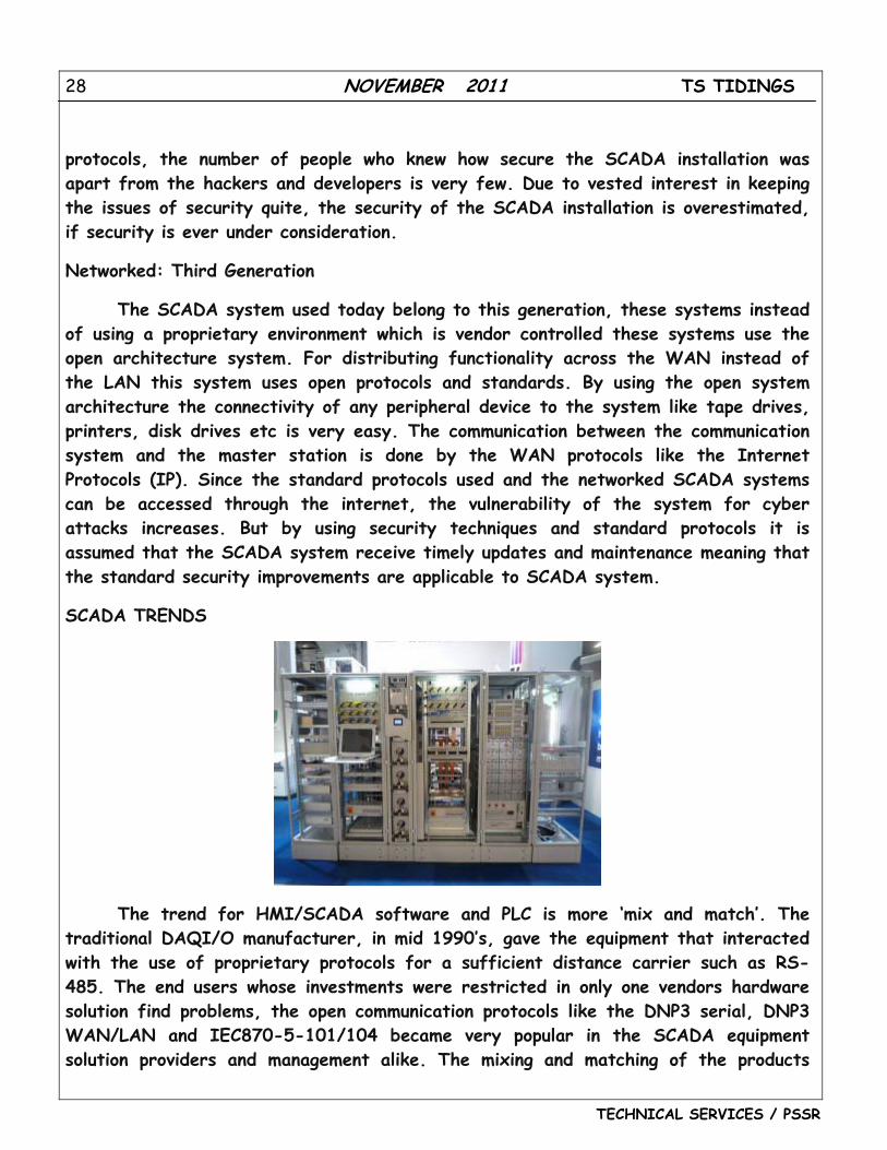
SCADA TRENDS
The trend for HMI/SCADA software and PLC is more ‘mix and match’. The traditional DAQI/O manufacturer, in mid 1990’s, gave the equipment that interacted with the use of proprietary protocols for a sufficient distance carrier such as RS-485. The end users whose investments were restricted in only one vendors hardware solution find problems, the open communication protocols like the DNP3 serial, DNP3 WAN/LAN and IEC870-5-101/104 became very popular in the SCADA equipment solution providers and management alike. The mixing and matching of the products
29 NOVEMBER 2011 TS TIDINGS
TECHNICAL SERVICES / PSSR
from different vendors for developing better solutions is possible because of the use of the Open architecture SCADA systems and hence were better than the solutions which were developed when the choices were restricted to one vendor’s products.
By the late 1990s instead of using the RS-485, the shift for open communications continued including the I O manufacturers, who used open message structures like Modbus ASCII and Modbus RTU (both developed by Modicon). By 2000, almost all the I O makers offered fully open interfacing like Modbus TCP instead of the IP and Ethernet.
The electrical system data should be time- tagged to the closest millisecond according to the North American Electric Reliability Corporation (NERC). To synchronize the distributed RTU clocks or RTU, the electrical system SCADA systems using the radio clocks provide Sequence of events recorder.
SCADA systems are now in line with the standard networking technologies. The old proprietary standards are being replaced by the TCP/IP and Ethernet protocols. But due to certain special frame-based network communication technology characteristics like synchronization, environment suitability, protocol selection and determinism have created certain issues in the adoption of the Ethernet in some specialized applications, Ethernet networks have been accepted by a majority of markets for HMI SCADA.
The ‘Next Generation’ protocols using XML web services and the other modern web technologies make themselves more IT supportable. A few examples of these protocols are Wonderware’s SuiteLink, GE Fanuc’s Proficy, I Gear’s Data Transport Utility, Rockwell Automation’s FactoryTalk and OPC-UA.
Some vendor’s have started offering application specific SCADA systems which are hosted on remote platforms all over the internet because of the emerging software as a service. Hence the need to commission and install systems at the user’s-end facility is not there anymore and this also take advantage of all the security features which are available in the Internet Technology, SSL and VPNs. Some concerns are the internet connection reliability, security and latency.
The SCADA systems are becoming omnipresent day by day. Web portals, web based products and thin clients have gained a lot of popularity with the major vendors. There is a pressing security question which arises due to the fact that there is a lot of convenience at end users viewing all their processes remotely. These considerations in some sectors of the internet services are considered solved but not
30 NOVEMBER 2011 TS TIDINGS
TECHNICAL SERVICES / PSSR
all the entities which are responsible for deploying the SCADA systems have really understood the changes in the threat scope and accessibility scope implicit in connecting any system to internet.
SCADA SECURITY ISSUES
The move to better standardized and more open solutions from the proprietary technologies along with increase in number of the connections between office networks and SCADA systems as well as Internet has led to more vulnerability to attacks- check references. Subsequently, SCADA-based systems’ security is being questioned as they are targets to cyberterrorism/cyberwarfare attacks.
Mainly, security researchers are looking into:
1. Concern lacking in security and lack of authentic deployment, operation and design in existing networks of SCADA.
2. By the use of proprietary interfaces and specialized protocols, the erroneous belief that the SCADA systems are benefiting by security through obscurity.
3. The erroneous belief about the SCADA networks being secure due to the fact that they are purportedly secured physically.
4. The erroneous belief about the SCADA networks being secure due to the fact that they are disconnected from internet, supposedly.
SCADA systems also are used for monitoring and controlling physical processes, examples being, distribution of water, traffic lights, electricity transmissions, gas transportation and oil pipelines and other systems used in the modern society. The SCADA systems’ security is primary as the destruction or compromise of the systems would have a bad impact on various areas of the society which have been removed from original compromise. Example- financial losses will be faced by the customers who receive electricity from the source, due to the blackout by the electrically compromised SCADA system. Its effect on new deployments and legacy SCADA will be seen.
The modern SCADA system has two threats. First is the unauthorized access for controlling software, be it human access or intentionally induced changes or virus infections or other threats on control host machine. Second is that of the packet access to network segments which host SCADA devices. In numerous cases, there remains less or no security on actual packet control protocol, therefore any person
31 NOVEMBER 2011 TS TIDINGS
TECHNICAL SERVICES / PSSR
sending packets to SCADA device is in position to control it. Often, SCADA users infer that VPN is enough protection and remain oblivious to the fact that physical access to network switches and jacks related to SCADA provides the capacity to bypass the security on control software and control SCADA networks. These physical access attacks can bypass the VPN security and firewall and can be put right by end point-to-endpoint authorization and authentication like these are frequently provided in world of non-SCADA by SSL which is an in-device and cryptographic techniques.
Various SCADA and the control product vendors are addressing these risks by developing specialized industrial VPN and firewall solutions for SCADA networks which are based on TCP/IP. Also, whitelisting solutions have been implemented due to their ability for preventing unauthorized and malware application changes while not having performance impacts belonging to the earlier antivirus scans. Moreover, the ISA Security Compliances Institute (ISCI) has been emerging for formalizing SCADA security test beginning from 2009.ISCI is equivalent to private certification and testing which has been done since 2007 by vendors. In the long run, ISA99 WG4 has defined standards which will supersede the earlier industry efforts of consortia, but not till 2011.
Due to the increase in interest in the SCADA vulnerabilities, vulnerability researchers have discovered vulnerabilities in the commercial software of SCADA and the SCADA techniques which are offensive, presented to general security community. In gas and electric utility systems, the big installed base having wireless and wired serial communications, has its vulnerability addressed in few cases by application of bump-in-the-wire devices which employ Advanced Encryption Standard and authentication encryption instead of replacing all the existing nodes.
32 NOVEMBER 2011 TS TIDINGS
TECHNICAL SERVICES / PSSR
UNITS WHICH HAVE ACHIEVED 100% OA
THERMAL
500 MW RAMAGUNDAM UNITS – 4, 5, 6 & 7
TALCHER UNIT – 2 & 4 SIMHADRI UNIT – 1
SIPAT UNIT – 4 VTPS UNIT - 7
210 MW
VIJAYAWADA UNITS – 2,3,4 & 6 MUDDANUR UNIT – 2 RAICHUR UNIT – 3 & 6