FC144 Highly-Accessible Catalysts for Durable High-Power Performance Anusorn Kongkanand (PI) General Motors, Fuel Cell Business May 1, 2019 This presentation does not contain any proprietary, confidential, or otherwise restricted information
Transcript
FC144
Highly-Accessible Catalysts for
Durable High-Power Performance
Anusorn Kongkanand (PI)
General Motors, Fuel Cell Business
May 1, 2019
This presentation does not contain any proprietary, confidential, or otherwise restricted information
Overview
Timeline
• Project start date: 1 Apr 2016
• Project end date: 30 Jun 2019
• Percent complete: 75%
Budget
• Total Funding Spent as of 12/31/18:
$2.4M
• Total DOE Project Value:
$4.0M (additional direct funding to NREL $0.6M)
• Cost Share: 21.7%
Barriers • B. Cost
– Decrease amount of precious metals.
• A. Durability
– Improve kinetic activity and high current density performance
• C. Performance
– Achieve and maintain high current densities at acceptably-high voltages
Partners
• Subcontractors: – 3M Company
– Carnegie Mellon University
– Cornell University
– Drexel University
– NREL
• Project lead: GM
2
Relevance:
--
---
--
carbon
Pt
ionomer
O2
Mass-transport Voltage Losses
H+, O2
1.75 A/cm2 on a 0.10
mgPt/cm2 cathode
O2 through Ionomer/Pt Interface H+ and O2 through Carbon
Measure the effect of leached Co2+ and Pt surface area 100% 100%
Develop dealloyed catalyst from ordered intermetallic alloy 100% 100%
Visualize carbon structure and Pt location on selected catalysts 100% 100%
Model baseline material 100% 100%
TASK 2 - Development of Dealloyed Catalyst with Preferred Catalyst Design Go/No-go criteria : >0.44 A/mgPGM, <40% mass activity loss with preferred design ✓
Develop dealloyed catalyst on preferred support 80% 100%
Implement selected ionomer and ionic liquid with selected catalysts 60% 100%
Visualize fresh PtCo/C and post-AST Pt/C 90% 100%
Model PtCo/C before and after AST 70% 100%
TASK 3 - Optimization for Durable HCD and LCD Performance Milestone: >1.1 W/cm2, >9.1 kWrated/gPt, and Q/ΔT <1.45 ✓ Jun 2019
Identify root cause and improve durability and performance of PtCo/C 20% 70%
Evaluate effect of selected ionomer/IL on HCD and durability of improved PtCo catalyst 10% 80%
Integrate new catalyst design with other state-of-the-art FC components 20% 80%
Make available to DOE the improved catalyst in 50 cm2 MEAs 10% 10%
6
Visualize and model improved catalyst 10% 50%
Improved HCD with Pt/C
Durable ORR activity PtCo/C
Durable HCD and LCD
2016 2017 2018
MilestoneGo/No-go
2019
Go/No-go
Materials dev’t Characterization Collaborations
Modeling
Catalyst dev’t MEA integration
Prof. Abruna
Catalyst dev’t
Prof. Muller
Electron Microscopy
Prof. Litster
Modeling
X-ray CT
Cation effect
Dr. Neyerlin
MEA diagnostics
Dr. Haug
Ionomer
Prof. Snyder
Ionic Liquid
Drs. Wang & Sasaki
Catalyst dev’t
Prof. Thompson
Support dev’t
Dr. Borup
Cation effect
APS & Dr. Myers
SAXS, XRF, XAS
Suppliers
Catalyst dev’t
Funded Partners
Unfunded
Partners
7
From 2018 AMR
Accessible-PtCo Stability
ORR Targets
0.44 A/mgPt BOL
0.26 A/mgPt EOT
➢ Although catalysts with Accessible-
porous carbons outperform other
catalysts at HCD (2 A/cm2) throughout
the test, they show larger % losses
of ORR MA and ECSA compared to
KB.
* HSC-en is an optimized and up-scale (20 g) of HSC-e † MA at 0.9 VRHE measured in cathodic direction ‡ H2/air, 94°C, 250 kPaabs, 65% RH, stoich 1.5/2 Porous Solid Accessible-Porous
H2/N2, 80°C, 100% RH
0.3
0.4
0.5
0.6
0.7
PtC
o/K
B
PtC
o/H
SC-c
PtC
o/V
PtC
o/H
SC-e
PtC
o/H
SC-e
n
PtC
o/H
SC-f
(0.0
6 P
t)
Vo
ltag
e a
t 2
A/c
m2
(V)
30%
51%
59%
62%
42%54%
00.10.20.30.40.50.60.70.8
OR
R M
ass
Act
ivit
y (A
/mg P
t)
0 10k 30k
loss
0
10
20
30
40
50
60
ECSA
HA
D(m
2 /g P
t)
†
‡
*
30 wt.% PtCo/C 50 cm2
8
Technical Accomplishment:
Improving Stability with Intermetallic Pt3Co
Pt Loss Determined by TEM
PNAS (2019) 116, 1974
30k
BOL
disordered
Pt3Co
annealed
Pt3Co
0
5
10
15
20
25
30
35
PtCo/HSC i-PtCo/HSC
Effe
ctiv
e EC
SA L
oss
(%)
disordered
Pt3Co
annealed
Pt3Co
Pt loss to membrane
Pt loss due to
coarsening in
cathode
Thermal annealing to encourage intermetallic
ordering decreases ORR activity, ECSA, and HCD
losses by about one half.
TEM confirms MEA results: less particle growth,
less Pt loss to membrane.
Changes in Co/Pt ratio in cathode catalyst were
comparable (~45%). 9
Technical Accomplishment:
Also Effective on Accessible-PtCo
Carbon Supports and Annealing Effects on HCD Stability
0.3
0.4
0.5
0.6
0.7
PtC
o/K
B
PtC
o/A
B
PtC
o/V
i-Pt
Co/K
B
PtC
o/H
SC-f
i-Pt
Co/H
SC-f
Vo
ltag
e at
2 A
/cm
2
0 10k 30k‡
Thermal annealing optimization study (time & temperature) was done on PtCo/KB and
PtCo/HSC-f.
Results from the best treatment condition are shown, although it was found that similar
results were achievable among a wide range of condition, reflecting its robustness.
Appears to be effective on accessible-porous carbon as well.
‡ H2/air, 94°C, 250 kPaabs, 65% RH, stoich 1.5/2
Error bars: two σ 10
Technical Accomplishment:
Pt/Co Composition Trade-off ‡
Voltages at LCD and HCD vs Pt/Co ratio Co loss to ionomer phase
0.30
0.35
0.40
0.45
0.50
0.55
0.78
0.79
0.80
0.81
0.82
0.83
Pt/Co=3.2 Pt/Co=3.8 Pt/Co=4.8 Pt
V a
t 2
A/c
m2
V a
t 0
.2 A
/cm
2†
0
2
4
6
8
10
12
0
2
4
6
8
10
12
Ion
om
er a
cid
sit
e ex
chan
ged
(%)
Co
co
nte
nt
(μg
/cm
2 MEA
)
Co2+ in ionomer
Co in cathode
Catalysts with higher Co content give higher LCD but lower HCD.
Noticeable amount of Co is lost from the catalyst even at beginning-of-life, further loss after
AST.
Trade-off is not simple, depending on users’ operating condition, drive cycle, and MEA
design.
Need to better quantify/monitor Co amount during life, and ultimately, make the catalyst
Catalyst cycling (0.6-0.95V, 30k cycles)mV loss at
0.8A/cm2 24 39* 25 8 tbd <30
Support cycling (1.0-1.5V, 5k cycles)mV loss at
1.5A/cm2 >500 >500 tbd tbd tbd <30 -
Metric Units
DOE
2020
Target
Project
TargetPtCo/HSC-f
Ordered-
PtCo/HSC-fPtCo/HSC-f
Ordered-
PtCo/KB
Reduce anode Pt loading by shifting to high ECSA Pt/HSC catalyst.
Will prepare MEAs (38cm2) for DOE validation at NREL.
19
Responses to Last Year AMR Reviewers’ Comments
• “should benchmark against new commercial catalysts, which are showing very high mass activity in MEAs”
➢ We routinely benchmark against suppliers’ catalysts. Our PtCo/KB and PtCo/V baseline catalysts reported here are competitive. Note that some high mass activity reported by some groups are due to difference in measurement protocols.
• “Investigate whether increased ORR activities after more conditioning has any effect on HCDs”
➢ It does. We’re aware of it and ensure that it does not affect our conclusion.
• Modeling “serves only as a confirmation of what is already understood”, “not apparent that it is critical to the project”, “benefit for the greater community are difficult to derive”
➢ Fuel cell is a complicated device and until we apply numbers with reasonable assumption to try to explain the phenomenon, it is impossible to prove the hypothesis. The model allows us to do so.
➢ Notable findings from modeling: (a) how internal vs external Pt dissolve/redeposit, (b) importance of high negative Pt surface charge in carbon pores on kinetic and proton transport, (c) existence of high O2 diffusion resistance in carbon pores. These will be published in detail.
• “should increase the understanding of ionic liquid stability” ➢ Although we agree that durability testing should be done, we do not have resource to do so.
Another issue is that we do not have a method to characterize the IL once it is made into an MEA, other than watching the voltage which is an indirect measurement. This complicates the effort.
➢ That being said, we value IL as a tool to understand the Pt-ionomer interface. It’s also shown that IL could mitigate Pt dissolution.
Future Work Validation
Evaluate durability of low-loaded (0.075 mgPt/cm2, cathode+anode) MEA. Employ MEA diagnostics and
modeling to understand performance loss.
Prepare MEAs for DOE validation at NREL.
Materials Development
Implement new ionomer on accessible-porous carbons.
Optimize IL application and evaluate potential durability benefit of IL.
Catalyst synthesis path for intermetallic ordered PtCo with well controlled size.
Fundamentals
Finalize catalyst particle-pore performance model and cation fundamental performance model.
Study effects of local lattice strain on ORR activity using STEM with pixel array detector.
Ex-situ measurement of O2 diffusivity in water-filled nanopores
Improved HCD with Pt/C
Durable ORR activity PtCo/C
Durable HCD and LCD
2016 2017 2018
MilestoneGo/No-go
2019
Go/No-go
Any proposed future work is subject to change based on funding levels. 21
Summary
Progress to DOE target status
➢ Advanced PGM Utilization status by 15% by reducing
Pt in both anode and cathode.
➢ Narrowed gap to 1 W/cm2 (150kPa) target (now 0.95 W/cm2).
Promising materials
Project period
4
6
8
10
12
14
2013 2014 2015 2016 2017 2018 2019 2020
Po
we
r (k
W/g
PG
M)
Year
DOE target 150kPa
Q/ΔT = 1.45 (0.67 V at 94°C)
➢ Intermetallic ordering was effective for improving durability of accessible-PtCo with minimal
performance penalty.
➢ While ionic liquid were beneficial for some PtCo/HSC, benefits on our best accessible-catalyst was not
yet realized. Potential merit on stability awaits confirmation in MEA.
Improved understanding of low-PGM electrode
➢ 3D-TEM and modeling confirmed that internal pore size (opening) is the key factor for good ORR
activity and transport properties in porous carbon catalysts.
➢ Ex-situ tests and modeling highlighted (a) importance of high negative Pt surface charge in carbon
pores on kinetic and proton transport and (b) unusually strong dependent of O2 diffusivity on carbon
pore size.
➢ STEM Nanobeam Diffraction allows study of how lattice strain and defect in Pt shell affect ORR
activity in MEAs.
22 This Year: 3 Articles, 12 Talks (3 invited)
Acknowledgements DOE
– Greg Kleen (Program Manager)
– Donna Ho (Technology Manager)
– Dan Berteletti
General Motors
– Aida Rodrigues, Yevita Brown, Sheryl Forbes, Charles
Gough (Contract Managers)
– Venkata Yarlagadda
– Michael K. Carpenter
– Yun Cai
– Thomas E. Moylan
– Joseph M. Ziegelbauer
– Ratandeep Singh Kukreja
– Wenbin Gu
– Srikanth Arisetty
– Roland Koestner
– Cristin L. Keary
– Qiang Li and team
– Peter Harvey and team
– Kathryn Stevick and team
– Tim Fuller
– Shruti Gondikar
– Mohammed Atwan
– Nagappan Ramaswamy
– Dave Masten
– Swami Kumaraguru
– Craig Gittleman
– Mark F. Mathias
3M
– Dr. Andrew Haug (sub-PI)
– Matthew Lindell
– Tyler Matthews
Carnegie Mellon University
– Prof. Shawn Litster (sub-PI)
– Shohei Ogawa
– Jonathan Braaten
– Leiming Hu
– Yuqi Guo
Cornell University
– Prof. David A. Muller (sub-PI)
– Prof. Héctor Abruña
– Elliot Padgett
– Matthew Ko
– Barnaby Levin
– Yin Xiong
– Yao Yang
Drexel University
– Prof. Joshua Snyder (sub-PI)
– Yawei Li
NREL
– Dr. K.C. Neyerlin (sub-PI)
– Luigi Osmieri
– Jason Christ
– Shaun Alia
– Jason Zack
ANL / APS
– Dr. Deborah J. Myers
– Dr. Nancy N. Kariuki
– Dr. Ross N. Andrews
– Dr. Jan Ilavsky
LANL
– Dr. Andrew M. Baker
– Dr. Rangachary Mukundan
– Dr. Rod L. Borup
Technical Back-Up Slides
24
-
Technical Accomplishment:
In-Operando Co2+ Migration with Nano-CT
Migration Cell Raw high-Z color mapping (Hydrogen pump config.)
(histogram adjusted)
Installed in nano CT
Co2+ attenuation mapping
Experimental details: 20 wt% Pt/V CL in X-ray view
Nafion 211 membrane
Migration under 1V conditions
Nano-CT imaging
LFOV (65x65 μm)
Absorption contrast mode
60s per image, bin1 (64 nm pixel)
>10 hour duration, data shown at 2 & 400 min
25
Cell front 0
*
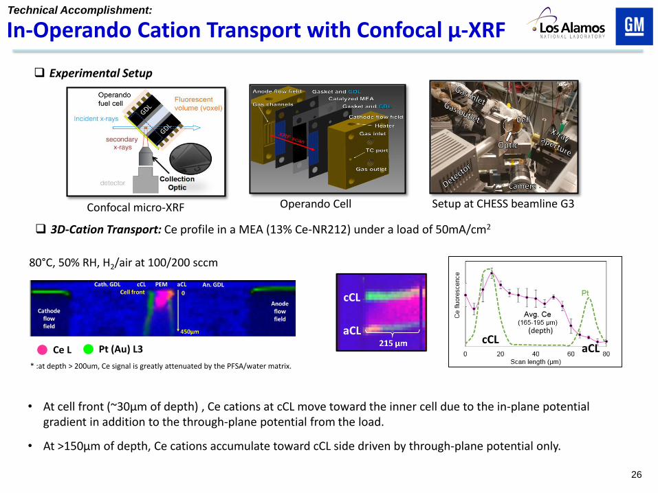
Technical Accomplishment:
In-Operando Cation Transport with Confocal μ-XRF
Experimental Setup
Setup at CHESS beamline G3 Confocal micro-XRF Operando Cell
3D-Cation Transport: Ce profile in a MEA (13% Ce-NR212) under a load of 50mA/cm2
• At cell front (~30µm of depth) , Ce cations at cCL move toward the inner cell due to the in-plane potential gradient in addition to the through-plane potential from the load.
• At >150µm of depth, Ce cations accumulate toward cCL side driven by through-plane potential only.
Ce L Pt (Au) L3
* :at depth > 200um, Ce signal is greatly attenuated by the PFSA/water matrix.
80°C, 50% RH, H2/air at 100/200 sccm
cCL
aCL cCL
aCL
(depth)
26
CO displacement charge at 0.4 V vs. RHE is lower
in the presence of IL, indicating decreased anionic
0.1 0.2 0.3 0.4 0.5 0.6 0.7 0.8 0.9-0.06
-0.04
-0.02
0.00
0.02
0.04
Curr
ent D
ensity (
mA
cm
-2 geo)
Potential (V vs RHE)
Pt(111)
Pt(111)+Nafion
Pt(111)+Nafion+IL -10 -5 0 5 10 15 20 25 30
-1.25
-1.00
-0.75
-0.50
-0.25
0.00
0.25
0.50
0.75
1.00
Curr
ent (
A)
Time (s)
Pt(111)
Pt(111)+Nafion
Pt(111)+Nafion+IL
-10 -5 0 5 10 15 20 25 30
-1
0
1
2
3
4
5
6
Curr
ent (
A)
Time (s)
Pt(111)
Pt(111)+Nafion
Pt(111)+Nafion+IL
CO displacement
0.2 V vs. RHE 0.4 V vs. RHE
0.2 0.3 0.4
-0.05
0.00
0.05
0.10
0.15
0.20
0.25
Pt(111)
Pt(111)+Nafion
Pt(111)+Nafion+IL
Covera
ge (
dis)
Potential (V vs RHE)
Technical Accomplishment:
IL Mediation of Nafion Specific Adsorption
Nafion/IL Thin Films on Pt(111)
0.1 M HClO4
SO3-
species
CO displacement below the Pt PZC, < 0.3 V vs.
RHE at pH 1, indicates increased H adsorption,
approaching that of bare Pt(111), in the presence of
Intermediary IL thin film both limits ionic species
specific adsorption, screening of SO3- groups, and