Highly Accurate Position Location for Future Precision Wireless Communication Theodore S. Rappaport tr51 @nyu.edu This work is supported by the NYU WIRELESS Industrial Affiliates Program and National Science Foundation (NSF) (Award Number: 1702967, 1731290 1555332, 1302336, and 1320472). March 11, 2020 A Presentation for NYU WIRELESS Industrial Affiliates
Transcript
Highly Accurate Position Location for Future Precision Wireless Communication
This work is supported by the NYU WIRELESS Industrial Affiliates Program and National Science Foundation (NSF) (Award Number: 1702967, 1731290 1555332, 1302336, and 1320472).
March 11, 2020
A Presentation forNYU WIRELESS Industrial Affiliates
2
Industrial Affiliates
Acknowledgement to our NYU WIRELESS Industrial Affiliates and NSF
This work is supported by the NYU WIRELESS Industrial Affiliates Program and National Science Foundation (NSF) (Award Number: 1702967, 1731290 1555332, 1302336, and 1320472).
• FCC and 3GPP Localization Accuracy Requirements.
• mmWave Localization Characteristics.
• 3GPP Localization Techniques.
• NYURay – 3D mmWave Ray Tracer.
• MAP-AT – Novel Localization Scheme.
• Localization Simulation Results in Real-World Indoor Environments.
Agenda
3
4
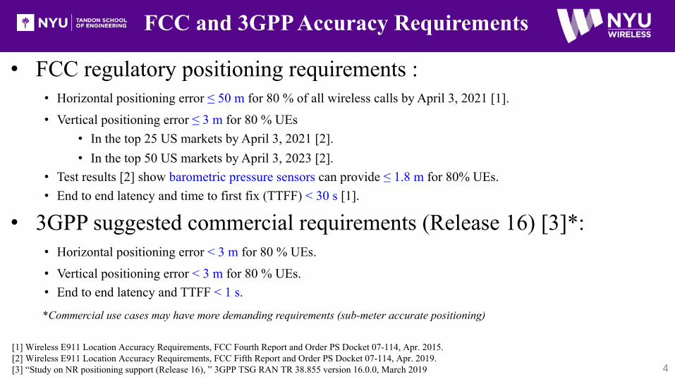
FCC and 3GPP Accuracy Requirements
• FCC regulatory positioning requirements :• Horizontal positioning error ≤ 50 m for 80 % of all wireless calls by April 3, 2021 [1].• Vertical positioning error ≤ 3 m for 80 % UEs
• In the top 25 US markets by April 3, 2021 [2]. • In the top 50 US markets by April 3, 2023 [2].
• Test results [2] show barometric pressure sensors can provide ≤ 1.8 m for 80% UEs. • End to end latency and time to first fix (TTFF) < 30 s [1].
• 3GPP suggested commercial requirements (Release 16) [3]*:• Horizontal positioning error < 3 m for 80 % UEs.• Vertical positioning error < 3 m for 80 % UEs.• End to end latency and TTFF < 1 s.
*Commercial use cases may have more demanding requirements (sub-meter accurate positioning)
[1] Wireless E911 Location Accuracy Requirements, FCC Fourth Report and Order PS Docket 07-114, Apr. 2015. [2] Wireless E911 Location Accuracy Requirements, FCC Fifth Report and Order PS Docket 07-114, Apr. 2019. [3] “Study on NR positioning support (Release 16), ” 3GPP TSG RAN TR 38.855 version 16.0.0, March 2019
LMU at eNB
5
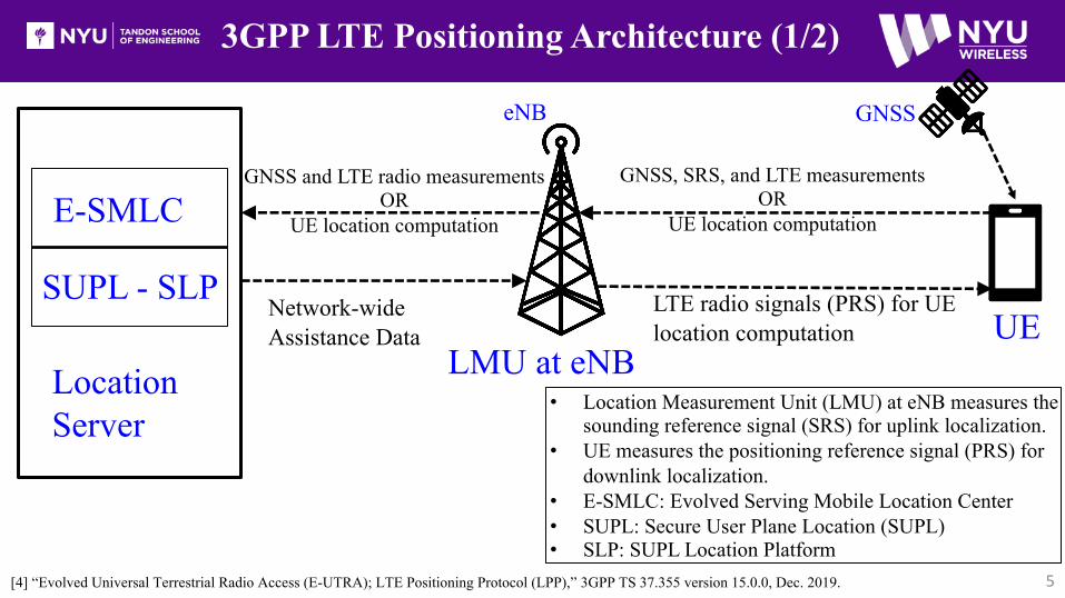
3GPP LTE Positioning Architecture (1/2)
UE
GNSS
LTE radio signals (PRS) for UE location computation
GNSS, SRS, and LTE measurements OR
UE location computation
Network-wide Assistance Data
GNSS and LTE radio measurements OR
UE location computationE-SMLC
[4] “Evolved Universal Terrestrial Radio Access (E-UTRA); LTE Positioning Protocol (LPP),” 3GPP TS 37.355 version 15.0.0, Dec. 2019.
• Location Measurement Unit (LMU) at eNB measures the sounding reference signal (SRS) for uplink localization.
• UE measures the positioning reference signal (PRS) for downlink localization.
• E-SMLC: Evolved Serving Mobile Location Center• SUPL: Secure User Plane Location (SUPL)• SLP: SUPL Location Platform
eNB
Location Server
SUPL - SLP
6
3GPP LTE Positioning Architecture (2/2)
Two types of “Location Solution” offered by 3GPP [4]:
1) Control Plane Location Solution
• Control Plane: The signaling connection in a network.
• Evolved Serving Mobile Location Center (E-SMLC) uses the control plane for user positioning.• Network prioritizes localization data over regular traffic - used by emergency services.
2) Secure User Plane Location (SUPL)
• Data Plane: The user data traffic carrying connection in a network.
• SUPL Location Platform (SLP) communicates with UE over data plane.
[4] “Evolved Universal Terrestrial Radio Access (E-UTRA); LTE Positioning Protocol (LPP),” 3GPP TS 37.355 version 15.0.0, Dec. 2019.
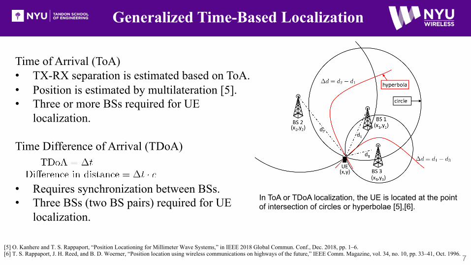
Generalized Time-Based Localization
7[5] O. Kanhere and T. S. Rappaport, “Position Locationing for Millimeter Wave Systems,” in IEEE 2018 Global Commun. Conf., Dec. 2018, pp. 1–6.[6] T. S. Rappaport, J. H. Reed, and B. D. Woerner, “Position location using wireless communications on highways of the future,” IEEE Comm. Magazine, vol. 34, no. 10, pp. 33–41, Oct. 1996.
Time of Arrival (ToA)• TX-RX separation is estimated based on ToA.• Position is estimated by multilateration [5].• Three or more BSs required for UE
localization.
Time Difference of Arrival (TDoA)
• Requires synchronization between BSs.• Three BSs (two BS pairs) required for UE
localization.
In ToA or TDoA localization, the UE is located at the point of intersection of circles or hyperbolae [5],[6].
8
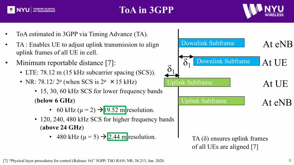
ToA in 3GPP
• ToA estimated in 3GPP via Timing Advance (TA).• TA : Enables UE to adjust uplink transmission to align
uplink frames of all UE in cell.• Minimum reportable distance [7]:
• LTE: 78.12 m (15 kHz subcarrier spacing (SCS)).• NR: 78.12/ 2μ (when SCS is 2μ ×15 kHz)
• 15, 30, 60 kHz SCS for lower frequency bands (below 6 GHz)
• 60 kHz (μ = 2) à19.52 m resolution. • 120, 240, 480 kHz SCS for higher frequency bands
(above 24 GHz)• 480 kHz (μ = 5) à 2.44 m resolution.
[7] “Physical layer procedures for control (Release 16)” 3GPP; TSG RAN; NR; 38.213, Jan. 2020.
TA (δ) ensures uplink frames of all UEs are aligned [7]
Downlink Subframe
Downlink Subframe
Uplink Subframe
Uplink Subframe
δ1δ1
At eNB
At UE
At UE
At eNB
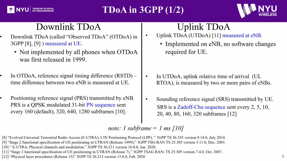
• Uplink TDoA (UTDoA) [11] measured at eNB.• Implemented on eNB, no software changes
required for UE.
• In UTDoA, uplink relative time of arrival (UL RTOA), is measured by two or more pairs of eNBs.
• Sounding reference signal (SRS) transmitted by UE.SRS is a Zadoff-Chu sequence sent every 2, 5, 10, 20, 40, 80, 160, 320 subframes [12]
9
TDoA in 3GPP (1/2)
• Downlink TDoA (called “Observed TDoA” (OTDoA) in 3GPP [8], [9] ) measured at UE. • Not implemented by all phones when OTDoA
was first released in 1999.
• In OTDoA, reference signal timing difference (RSTD) –time difference between two eNB is measured at UE.
• Positioning reference signal (PRS) transmitted by eNB. PRS is a QPSK modulated 31-bit PN sequence sent every 160 (default), 320, 640, 1280 subframes [10].
[8] “Evolved Universal Terrestrial Radio Access (E-UTRA); LTE Positioning Protocol (LPP), ” 3GPP TS 36.355 version 9.14.0, July 2014.[9] “Stage 2 functional specification of UE positioning in UTRAN (Release 1999),” 3GPP TSG-RAN TS 25.305 version 3.11.0, Dec. 2003.[10] “ E-UTRA; Physical channels and modulation,” 3GPP TS 36.211 version 16.0.0, Jan. 2020.[11] “Stage 2 functional specification of UE positioning in UTRAN (Release 7),” 3GPP TSAG RAN; TS 25.305 version 7.4.0, Oct. 2007. [12] “Physical layer procedures (Release 15)” 3GPP TS 36.213 version 15.8.0, Feb. 2020
Downlink TDoA Uplink TDoA
note: 1 subframe = 1 ms [10]
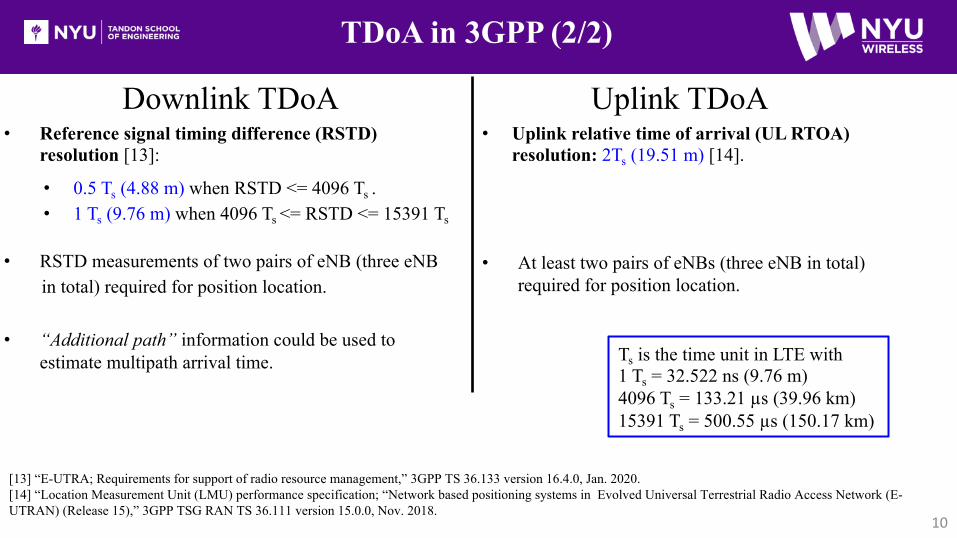
• Uplink relative time of arrival (UL RTOA) resolution: 2Ts (19.51 m) [14].
• At least two pairs of eNBs (three eNB in total) required for position location.
10
TDoA in 3GPP (2/2)
• Reference signal timing difference (RSTD) resolution [13]:
• RSTD measurements of two pairs of eNB (three eNB in total) required for position location.
• “Additional path” information could be used to estimate multipath arrival time.
[13] “E-UTRA; Requirements for support of radio resource management,” 3GPP TS 36.133 version 16.4.0, Jan. 2020. [14] “Location Measurement Unit (LMU) performance specification; “Network based positioning systems in Evolved Universal Terrestrial Radio Access Network (E-UTRAN) (Release 15),” 3GPP TSG RAN TS 36.111 version 15.0.0, Nov. 2018.
Ts is the time unit in LTE with1 Ts = 32.522 ns (9.76 m)4096 Ts = 133.21 µs (39.96 km)15391 Ts = 500.55 µs (150.17 km)
Downlink TDoA Uplink TDoA
• 0.5 Ts (4.88 m) when RSTD <= 4096 Ts .• 1 Ts (9.76 m) when 4096 Ts <= RSTD <= 15391 Ts
11
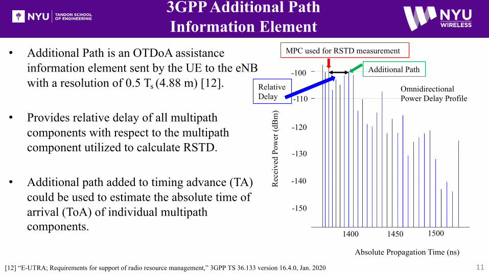
3GPP Additional Path Information Element
• Additional Path is an OTDoA assistance information element sent by the UE to the eNBwith a resolution of 0.5 Ts (4.88 m) [12].
• Provides relative delay of all multipath components with respect to the multipath component utilized to calculate RSTD.
• Additional path added to timing advance (TA) could be used to estimate the absolute time of arrival (ToA) of individual multipath components.
[12] “E-UTRA; Requirements for support of radio resource management,” 3GPP TS 36.133 version 16.4.0, Jan. 2020
1400 1450 1500
Absolute Propagation Time (ns)
Rec
eive
d Po
wer
(dB
m)
-150
-140
-130
-120
-110
-100
MPC used for RSTD measurement
Additional Path
Relative Delay
Omnidirectional Power Delay Profile
12
3GPP Angle of Arrival (AoA)
• Single AoA per UE, estimated only at eNB.• Angular resolution of 0.5°[12].• No beam sweeping procedure found in the standard to date.
• Beam sweeping could be carried out with an exhaustive search along predefined codebook directions at eNB and UE.
[12] “E-UTRA; Requirements for support of radio resource management,” 3GPP TS 36.133 version 16.4.0, Jan. 2020.
UE
eNB1
The eNB estimates one AoA per UE. The UE position is calculated using geometry.
𝜃!𝜃"
eNB2
Drawbacks of ToA, TDoA, AoAPositioning Techniques
13
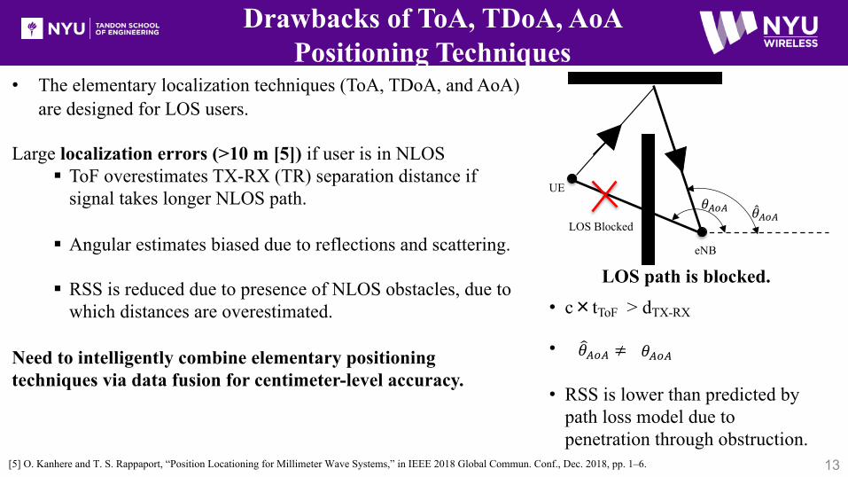
• The elementary localization techniques (ToA, TDoA, and AoA) are designed for LOS users.
Large localization errors (>10 m [5]) if user is in NLOS§ ToF overestimates TX-RX (TR) separation distance if
signal takes longer NLOS path.
§ Angular estimates biased due to reflections and scattering.
§ RSS is reduced due to presence of NLOS obstacles, due to which distances are overestimated.
Need to intelligently combine elementary positioning techniques via data fusion for centimeter-level accuracy.
[5] O. Kanhere and T. S. Rappaport, “Position Locationing for Millimeter Wave Systems,” in IEEE 2018 Global Commun. Conf., Dec. 2018, pp. 1–6.
LOS path is blocked.• c×tToF > dTX-RX
•
• RSS is lower than predicted by path loss model due to penetration through obstruction.
𝜃!"!"𝜃!"! ≠
UE
LOS Blocked"𝜃#$#
𝜃#$#
eNB
Ray Tracing for Positioning
14
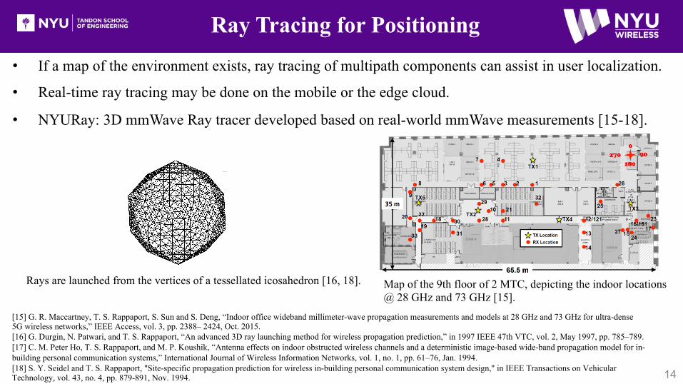
• If a map of the environment exists, ray tracing of multipath components can assist in user localization.
• Real-time ray tracing may be done on the mobile or the edge cloud.
• NYURay: 3D mmWave Ray tracer developed based on real-world mmWave measurements [15-18].
[15] G. R. Maccartney, T. S. Rappaport, S. Sun and S. Deng, “Indoor office wideband millimeter-wave propagation measurements and models at 28 GHz and 73 GHz for ultra-dense 5G wireless networks,” IEEE Access, vol. 3, pp. 2388– 2424, Oct. 2015.[16] G. Durgin, N. Patwari, and T. S. Rappaport, “An advanced 3D ray launching method for wireless propagation prediction,” in 1997 IEEE 47th VTC, vol. 2, May 1997, pp. 785–789.[17] C. M. Peter Ho, T. S. Rappaport, and M. P. Koushik, “Antenna effects on indoor obstructed wireless channels and a deterministic image-based wide-band propagation model for in-building personal communication systems,” International Journal of Wireless Information Networks, vol. 1, no. 1, pp. 61–76, Jan. 1994.[18] S. Y. Seidel and T. S. Rappaport, "Site-specific propagation prediction for wireless in-building personal communication system design," in IEEE Transactions on Vehicular Technology, vol. 43, no. 4, pp. 879-891, Nov. 1994.
Rays are launched from the vertices of a tessellated icosahedron [16, 18]. Map of the 9th floor of 2 MTC, depicting the indoor locations @ 28 GHz and 73 GHz [15].
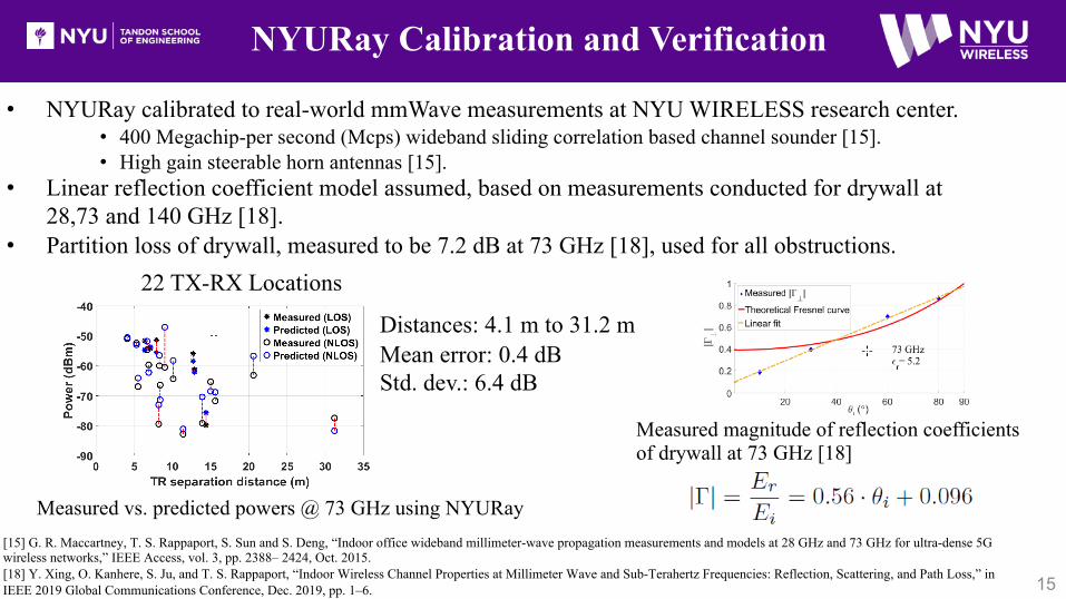
• NYURay calibrated to real-world mmWave measurements at NYU WIRELESS research center.• 400 Megachip-per second (Mcps) wideband sliding correlation based channel sounder [15].• High gain steerable horn antennas [15].
• Linear reflection coefficient model assumed, based on measurements conducted for drywall at 28,73 and 140 GHz [18].
• Partition loss of drywall, measured to be 7.2 dB at 73 GHz [18], used for all obstructions.
NYURay Calibration and Verification
15
Measured magnitude of reflection coefficients of drywall at 73 GHz [18]
[15] G. R. Maccartney, T. S. Rappaport, S. Sun and S. Deng, “Indoor office wideband millimeter-wave propagation measurements and models at 28 GHz and 73 GHz for ultra-dense 5G wireless networks,” IEEE Access, vol. 3, pp. 2388– 2424, Oct. 2015.[18] Y. Xing, O. Kanhere, S. Ju, and T. S. Rappaport, “Indoor Wireless Channel Properties at Millimeter Wave and Sub-Terahertz Frequencies: Reflection, Scattering, and Path Loss,” in IEEE 2019 Global Communications Conference, Dec. 2019, pp. 1–6.
Measured vs. predicted powers @ 73 GHz using NYURay
Distances: 4.1 m to 31.2 mMean error: 0.4 dBStd. dev.: 6.4 dB
22 TX-RX Locations
Implementing MAP-AT : A Novel Localization Method
16
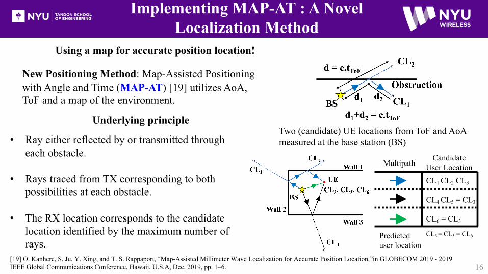
• Ray either reflected by or transmitted through each obstacle.
• Rays traced from TX corresponding to both possibilities at each obstacle.
• The RX location corresponds to the candidate location identified by the maximum number of rays.
Underlying principle
New Positioning Method: Map-Assisted Positioning with Angle and Time (MAP-AT) [19] utilizes AoA, ToF and a map of the environment.
Two (candidate) UE locations from ToF and AoAmeasured at the base station (BS)
Multipath CandidateUser LocationCL1 CL2 CL3
CL4 CL5 = CL3
CL6 = CL3
Predicted user location
CL3 = CL5 = CL6
Using a map for accurate position location!
[19] O. Kanhere, S. Ju, Y. Xing, and T. S. Rappaport, “Map-Assisted Millimeter Wave Localization for Accurate Position Location,”in GLOBECOM 2019 - 2019 IEEE Global Communications Conference, Hawaii, U.S.A, Dec. 2019, pp. 1–6.
Nrms = 100 simulations conducted at NRX = 100randomly selected RX locations, (a total of 10,000 simulation runs) over TX-RX distances ranged from 1.5 m to 24.5 m at NYU WIRELESS Research center.
Simulation Setup and Results forEvaluating MAP-AT using NYURay @ 73 GHz
17
The 100 user locations, selected uniformly at random over the floorplan of NYU WIRELESS Research Center are depicted above.
UE LocationsBS Locations
65.5 m
CDF of the rms localization error when a user is localized using one, two, and three BSs, with Additive Gaussian noise added to angular and time estimates σAoD = 0.5°.
3 BS 2 BS
1 BS
Simulation Results
18
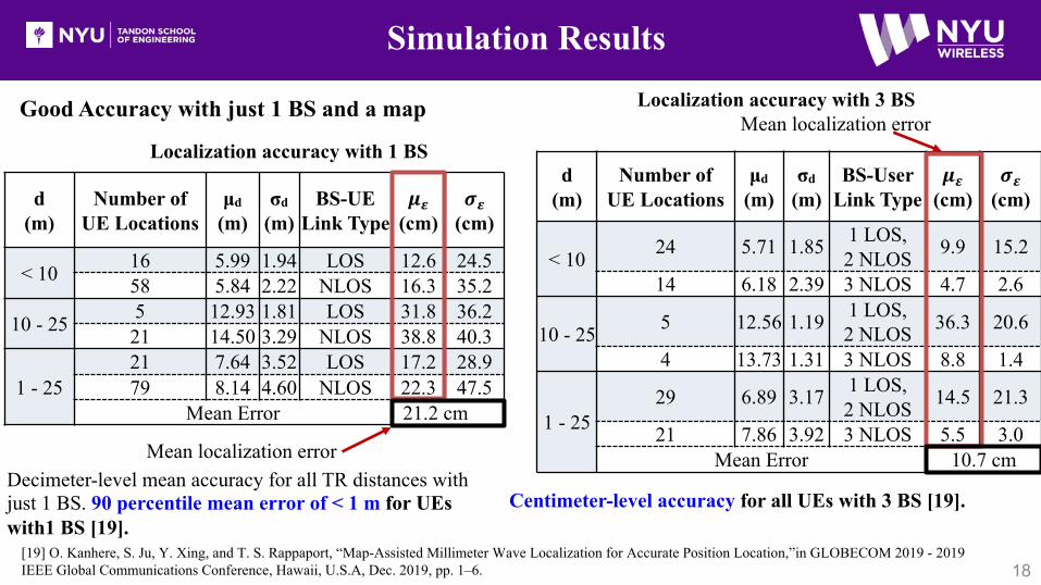
Decimeter-level mean accuracy for all TR distances with just 1 BS. 90 percentile mean error of < 1 m for UEs with1 BS [19].
Centimeter-level accuracy for all UEs with 3 BS [19].
d (m)
Number of UE Locations
μd(m)
σd(m)
BS-User Link Type
𝝁𝜺(cm)
𝝈𝜺(cm)
< 10 24 5.71 1.85 1 LOS, 2 NLOS 9.9 15.2
14 6.18 2.39 3 NLOS 4.7 2.6
10 - 25 5 12.56 1.19 1 LOS, 2 NLOS 36.3 20.6
4 13.73 1.31 3 NLOS 8.8 1.4
1 - 2529 6.89 3.17 1 LOS,
2 NLOS 14.5 21.3
21 7.86 3.92 3 NLOS 5.5 3.0Mean Error 10.7 cm
Mean localization error
[19] O. Kanhere, S. Ju, Y. Xing, and T. S. Rappaport, “Map-Assisted Millimeter Wave Localization for Accurate Position Location,”in GLOBECOM 2019 - 2019 IEEE Global Communications Conference, Hawaii, U.S.A, Dec. 2019, pp. 1–6.
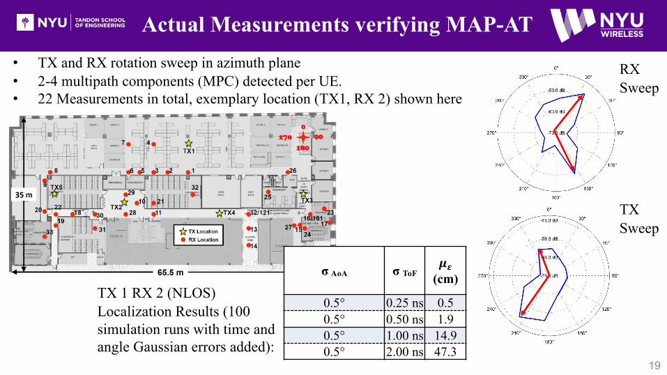
• TX and RX rotation sweep in azimuth plane• 2-4 multipath components (MPC) detected per UE.• 22 Measurements in total, exemplary location (TX1, RX 2) shown here
TX 1 RX 2 (NLOS) Localization Results (100 simulation runs with time and angle Gaussian errors added):
Conclusion
20
• 3GPP standard will support precise positioning in 5G networks.
• NYURay – a 3D mmWave ray tracer developed based on real-world channel measurements.
• We will be able to generate or use a 3-D map of our surroundings on-the-fly using mmWave radio.
• Decimeter-level indoor localization (mean localization error of 21.2 cm) possible at mmWave frequencies using 1 BS, with map information fused with angular and temporal information.
• Indoor localization performance improves with additional BS: 10.7 cm mean localization with 3 BS.
• mmWave localization is a promising solution for cm-level accuracy!
[1] Wireless E911 Location Accuracy Requirements, FCC Fourth Report and Order PS Docket 07-114, Apr. 2015. [2] Wireless E911 Location Accuracy Requirements, FCC Fifth Report and Order PS Docket 07-114, Apr. 2019. [3] “Study on NR positioning support (Release 16), ” 3GPP TSG RAN TR 38.855 version 16.0.0, March 2019. [4] “Evolved Universal Terrestrial Radio Access (E-UTRA); LTE Positioning Protocol (LPP),” 3GPP TS 37.355 version 15.0.0, Dec. 2019.[5] O. Kanhere and T. S. Rappaport, “Position Locationing for Millimeter Wave Systems,” in IEEE 2018 Global Commun. Conf., Dec. 2018, pp. 1–6.[6] T. S. Rappaport, J. H. Reed, and B. D. Woerner, “Position location using wireless communications on highways of the future,” IEEE Comm. Magazine, vol. 34, no. 10, pp. 33–41, Oct. 1996.[7] “Physical layer procedures for control (Release 16)” 3GPP; TSG RAN; NR; 38.213, Jan. 2020.[8] “Evolved Universal Terrestrial Radio Access (E-UTRA); LTE Positioning Protocol (LPP), ” 3GPP TS 36.355 version 9.14.0, July 2014. [9] “Stage 2 functional specification of UE positioning in UTRAN (Release 1999),” 3GPP TSG-RAN TS 25.305 version 3.11.0, Dec. 2003.[10] “ E-UTRA; Physical channels and modulation,” 3GPP TS 36.211 version 16.0.0, Jan. 2020[11] “Stage 2 functional specification of UE positioning in UTRAN (Release 7),” 3GPP TSAG RAN; TS 25.305 version 7.4.0, Oct. 2007. [12] “Physical layer procedures (Release 15)” 3GPP TS 36.213 version 15.8.0, Feb. 2020
References (1/2)
21
[13] “E-UTRA; Requirements for support of radio resource management,” 3GPP TS 36.133 version 16.4.0, Jan. 2020. [14] “Location Measurement Unit (LMU) performance specification; “Network based positioning systems in Evolved Universal Terrestrial Radio Access Network (E-UTRAN) (Release 15),” 3GPP TSG RAN TS 36.111 version 15.0.0, Nov. 2018.[15] G. R. Maccartney, T. S. Rappaport, S. Sun and S. Deng, “Indoor office wideband millimeter-wave propagation measurements and models at 28 GHz and 73 GHz for ultra-dense 5G wireless networks,” IEEE Access, vol. 3, pp. 2388– 2424, Oct. 2015.[16] G. Durgin, N. Patwari, and T. S. Rappaport, “An advanced 3D ray launching method for wireless propagation prediction,” in 1997 IEEE 47th VTC, vol. 2, May 1997, pp. 785–789.[17] C. M. Peter Ho, T. S. Rappaport, and M. P. Koushik, “Antenna effects on indoor obstructed wireless channels and a deterministic image-based wide-band propagation model for in-building personal communication systems,” International Journal of Wireless Information Networks, vol. 1, no. 1, pp. 61–76, Jan. 1994.[18] S. Y. Seidel and T. S. Rappaport, "Site-specific propagation prediction for wireless in-building personal communication system design," in IEEE Transactions on Vehicular Technology, vol. 43, no. 4, pp. 879-891, Nov. 1994.[19] O. Kanhere, S. Ju, Y. Xing, and T. S. Rappaport, “Map-Assisted Millimeter Wave Localization for Accurate Position Location,”in GLOBECOM 2019 - 2019 IEEE Global Communications Conference, Hawaii, U.S.A, Dec. 2019, pp. 1–6.