Received 18th September 2015,Accepted 20th November 2015
DOI: 10.1039/c5nr06431g
www.rsc.org/nanoscale
Highly stretchable MoS2 kirigami
Paul Z. Hanakata,a Zenan Qi,b David K. Campbell*a and Harold S. Park*b
We report the results of classical molecular dynamics simulations focused on studying the mechanical
properties of MoS2 kirigami. Several different kirigami structures were studied based upon two simple
non-dimensional parameters, which are related to the density of cuts, as well as the ratio of the over-
lapping cut length to the nanoribbon length. Our key findings are significant enhancements in tensile
yield (by a factor of four) and fracture strains (by a factor of six) as compared to pristine MoS2 nanoribbons.
These results, in conjunction with recent results on graphene, suggest that the kirigami approach may be
generally useful for enhancing the ductility of two-dimensional nanomaterials.
Molybdenum disulfide (MoS2) has been intensely studied inrecent years as an alternative two-dimensional (2D) material tographene. This interest has arisen in large part because (i)MoS2 exhibits a direct band gap of nearly 2 eV in monolayerform which renders it suitable for photovoltaics;1 and (ii) ithas potential for many other technological applications,ranging from energy storage to valleytonics.2–5
The mechanical properties of MoS2 have also been exploredrecently, through both experimental6–8 and theoreticalmethods.9–12 That MoS2 has been reported experimentally tobe more ductile than graphene8 naturally raises the criticalissue of developing new approaches to further enhancing theductility of 2D materials.
One approach that has recently been proposed towards thisend is “kirigami”, the Japanese technique of paper cutting, inwhich cutting is used to change the morphology of a structure.This approach has traditionally been applied to bulk materialsand recently to micro-scale materials,13–15 though recentexperimental16 and theoretical17 works have shown thebenefits of kirigami for the stretchability of graphene.
Our objective in the present work is to build upon previoussuccesses in applying kirigami concepts to graphene17 toinvestigate their effectiveness in enhancing the ductility of adifferent 2D material, MoS2, which is structurally morecomplex than monolayer graphene due to its three-layer struc-ture involving multiple atom types. We accomplish this usingclassical molecular dynamics (MD) with a recently developedStillinger-Weber potential.18 We find that kirigami can sub-stantially enhance the yield and fracture strains of monolayer
MoS2, with increases that exceed those previously seen inmonolayer graphene.17
We performed MD simulations using the Sandia-developedopen source code LAMMPS19,20 and employing the Stillinger-Weber potential for MoS2 of Jiang.18 All simulations were per-formed on single-layer MoS2 sheets. Of relevance to the resultsin this work, we note that while the Stillinger-Weber potentialdoes not have a term explicitly devoted to rotations, it doescontain two and three-body terms including angular depen-dencies, which are important for out-of-plane deformations.Furthermore, the Stillinger-Weber potential of Jiang18 was fitto the phonon spectrum of single-layer MoS2, which includesboth in and out-of-plane vibrational motions. As a result, theStillinger-Weber potential should do a reasonable job of cap-turing out-of-plane deformations that involve angle changes,such as rotations.
The MoS2 kirigami was made by cutting an MoS2 nano-ribbon, which had free edges without additional surfacetreatment or termination. A schematic view of the kirigamistructure and the relevant geometric parameters is shown inFig. 1. The key geometric parameters are the nanoribbonlength L0, the width b, the height of each interior cut w, thewidth of each interior cut c, and the distance between succes-sive cuts d. We considered kirigami for both zig-zag (ZZ) andarmchair (AC) edges. A representative AC MoS2 kirigami con-sisting a number of N ∼ 12 000 atoms with a nanoribbonlength L0 ∼ 450 Å, width b ∼ 100 Å, height of each interior cutw ∼ 70 Å, width of each interior cut c ∼ 11 Å, and distancebetween successive cuts d ∼ 55 Å is shown in Fig. 1.
The MD simulations were performed as follows. Thekirigami was first relaxed for 200 ps within the NVT (constantnumber of atoms N, volume V and temperature T ) ensemble atlow temperature (4.2 K), while non-periodic boundary con-ditions were used in all three directions. The kirigami was sub-sequently deformed in tension by applying uniform
aDepartment of Physics, Boston University, Boston, MA 02215, USA.
E-mail: [email protected]; Tel: +1 617-353-1948bDepartment of Mechanical Engineering, Boston University, Boston, MA 02215, USA.
displacement loading on both ends, such that the kirigamiwas pulled apart until fracture occurred. We note that in actualapplications, the MoS2 kirigami will likely lie on a substrate,and thus adhesive interactions with the substrate may impactthe deformation characteristics. In the present work, we focuson the intrinsic stretchability of the MoS2 kirigami whileleaving the interactions with a substrate for future work.
In addition, we simulated MoS2 sheets (defined as mono-layer MoS2 with periodic boundary conditions in the plane)and pristine nanoribbons with no cuts for comparative pur-poses. The calculated fracture strains εf, fracture stresses σ3Df ,and Young’s modulus Y3D are tabulated in Table 1. The resultsare in reasonably good agreement with the experimental andfirst-principles studies of MoS2 monolayer sheets.6,8 †
In Fig. 2(a), we plot a representative stress–strain curve ofMoS2 kirigami. For this, and the subsequent discussion, weintroduce two non-dimensional geometric parameters α =(w − 0.5b)/L0 and β = (0.5d − c)/L0, which were also previouslyused to describe graphene kirigami.17 α represents the ratio ofthe overlapping cut length to the nanoribbon length, while β
represents the ratio of overlapping width to the nanoribbonlength. Put another way, α describes the geometry orthogonalto the loading direction, while β describes the geometry paral-lel to the loading direction. Fig. 2(a) shows the stress–strain forthe specific choices of α = 0.0866, and β = 0.0375, which were
obtained by choosing b = 101.312 Å, L0 = 438.693 Å, w =88.648 Å, c = 10.967 Å, and d = 54.837 Å. In contrast, Fig. 2(b)shows the change in the stress–strain response if β = 0.0375 iskept constant while α changes. This is achieved by changing wwhile keeping other geometric parameters constant. We alsonote that the 2D stress was calculated as stress (in directionparallel to the applied strain) times simulation box size per-pendicular to the plane σ × t to remove any issues in calculat-ing the thickness,10 while the stress was obtained using theviral theorem, as is done in LAMMPS.
It can be seen that there are generally three major stages ofdeformation for the kirigami, as separated by the dashed linesin Fig. 2(a). In the first stage (region I), the deformation occursvia elastic bond stretching, and neither flipping nor rotation ofthe monolayer MoS2 sheet is observed, as shown in Fig. 3. Inprevious work on graphene kirigami, it was found that the kiri-gami rotates and flips in the first stage instead of stretchingthe bonds.17 This does not occur for kirigami in MoS2 in thisfirst stage because the bending modulus of MoS2 is nearlyseven times higher than that of graphene.10
In the second stage (region II), for tensile strains (ε) exceed-ing about 10%, further strain hardening occurs. Kirigami pat-terning allows the MoS2 monolayer to exhibit out-of-plane
Table 1 Comparison of mechanical properties of MoS2 sheets and pris-tine nanoribbons in the armchair (AC) and zigzag (ZZ) direction
Fig. 2 (Color online) Stress–strain curves of AC MoS2 kirigami, wherethe 2D stress was calculated as the stress σ times the simulation box sizet. (a) Stress–strain curve for constant α = 0.0866, β = 0.0375. (b) Stress–strain curve for AC kirigami keeping β = 0.0375 constant and varying α.Note the brittle fracture of the pristine MoS2 nanoribbon. In general, thestrain in region III increases substantially for α > 0.
Fig. 1 (Color online) Schematic of the MoS2 kirigami, with key geo-metric parameters labeled. The kirigami is deformed via tensile displace-ment loading that is applied at the two ends in the direction indicated bythe arrows. Top image represents a top view of the kirigami.
† In the above table, 3D stresses σ3Df are calculated as σ2Df /th, where th is theeffective thickness with a value of ∼6 Å.
deflections, as shown in Fig. 3, which permits the MoS2 mono-layer to undergo additional tensile deformation, which is incontrast to the brittle fracture observed for the pristine nano-ribbon immediately following the initial yielding event, asshown in Fig. 2(b). Furthermore, the out-of-plane deflectionscause the slope of the stress–strain curve in region II to besmaller than that in region I. This is because of the change indeformation mechanism from purely elastic stretching ofbonds in region I, to a combination of stretching and out ofplane buckling in region II.
Local bond breaking near the edges starts to occur at thetensile strain of ε = 35%. The occurrence of bond breaking isusually defined as the yield point, and signifies the demarka-tion between regions II and III. This local bond breakingoccurs due to the concentrated stress at the edges connectingeach slab, as previously observed in graphene kirigami.17 Atthis stage, each kirigami unit is held by a small connectingribbon which allows the monolayer to be almost foldable.Fig. 3 (stages 1 to 3) shows how the inner cut surface areahaving initial area w × c and the height of the monolayer(largest out-of-plane distance between S atoms) can change sig-nificantly during the tensile elongation.
In the final stage, after more than 62.5% tensile strain, frac-ture and thus failure of the kirigami nanoribbon is observed.Unlike the pristine nanoribbon, the yield point can differ sub-stantially from the fracture strain, and the difference increaseswith increasing cut-overlap, which was described previously, asshown in Fig. 2(b). Thus, it is important to quantify the yieldpoint of the kirigami, as it defines the beginning of the irre-versible deformation regime. Note that these regions varydepending on the kirigami structure, as shown in Fig. 2(b).
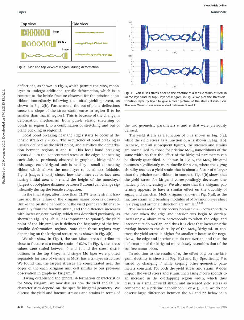
We also show, in Fig. 4, the von Mises stress distributionclose to fracture at a tensile strain of 62%. In Fig. 4, the stressvalues were scaled between 0 and 1, and the stress distri-butions in the top S layer and single Mo layer were plottedseparately for ease of viewing as MoS2 has a tri-layer structure.We found that the largest stresses are concentrated near theedges of the each kirigami unit cell similar to our previousobservation in graphene kirigami.17
Having established the general deformation characteristicsfor MoS2 kirigami, we now discuss how the yield and failurecharacteristics depend on the specific kirigami geometry. Wediscuss the yield and fracture stresses and strains in terms of
the two geometric parameters α and β that were previouslydefined.
The yield strain as a function of α is shown in Fig. 5(a),while the yield stress as a function of α is shown in Fig. 5(b).In these, and all subsequent figures, the stresses and strainsare normalized by those for pristine MoS2 nanoribbons of thesame width so that the effect of the kirigami parameters canbe directly quantified. As shown in Fig. 5, the MoS2 kirigamibecomes significantly more ductile for α > 0, where the zigzagchirality reaches a yield strain that is about a factor of 6 largerthan the pristine nanoribbon. In contrast, Fig. 5(b) shows thatthe yield stress for kirigami correspondingly decreases dra-matically for increasing α. We also note that the kirigami pat-terning appears to have a similar effect on the ductility ofzigzag and armchair MoS2 kirigami (shown in Fig. 5(a)), as thefracture strain and bending modulus of MoS2 monolayer sheetin zigzag and armchair direction are similar.10,18
The increased ductility occurs because α = 0 corresponds tothe case when the edge and interior cuts begin to overlap.Increasing α above zero corresponds to when the edge andinterior cuts do overlap, and thus it is clear that increasing theoverlap increases the ductility of the MoS2 kirigami. In con-trast, the yield stress is higher for smaller α because for nega-tive α, the edge and interior cuts do not overlap, and thus thedeformation of the kirigami more closely resembles that of thecut-free nanoribbon.
In addition to the results of α, the effect of β on the kiri-gami ductility is shown in Fig. 6(a) and (b). Specifically, β isvaried by changing d while keeping other geometric para-meters constant. For both the yield stress and strain, β doesimpact the yield stress and strain. Increasing β corresponds toan increase in the overlapping region width, which thusresults in a smaller yield strain, and increased yield stress ascompared to a pristine nanoribbon. For β ≥ 0.03, we do notobserve large differences between the AC and ZZ behavior in
Fig. 3 Side and top views of kirigami during deformation.
Fig. 4 Von Mises stress prior to the fracture at a tensile strain of 62% in(a) Mo layer and (b) top S layer of kirigami in Fig. 3. We plot the stress dis-tribution layer by layer to give a clear picture of the stress distribution.The von Mises stress were scaled between 0 and 1.
the case of varying β because increasing β (or decreasing thecut density) makes the kirigami more pristine, leading tosimilar values of fracture stress and strain in the AC or ZZdirection (see Table 1). Our results suggest that the failurestrain can be maximized by increasing the overlappingcut (increasing α) and increasing density of the cuts (decreas-ing β).
Recently, Guo et al. showed stretchability of metal electro-des can be enhanced by creating geometries similar to theones illustrated in Fig. 1.15 Adopting the geometric ratiosdetermining fracture strain described in ref. 15, we foundsimilar trends: the fracture strain increases with decreasingðb� wÞ
cand increases with increasing
bd. It is interesting to see
that a similar trend is observed at a different length scale (anatomically-thin monolayer in this work as compared to a ≈40 nm thin film in the work of Guo et al.), and for a differentmaterial system (MoS2 in this work, nanocrystalline gold in thework of Guo et al.), which suggests that the fracture strain inpatterned membranes can be described entirely by geometricparameters.
It is also interesting to note that the yield and fracturestrain enhancements shown in Fig. 5(a) exceed those pre-
viously reported for monolayer graphene kirigami.17 The mainreason for this is that the failure strain for the normalizingconstant, that of a pristine nanoribbon of the same width, issmaller for MoS2. As shown in Table 1, this value is about13%, whereas the value for a pristine graphene nanoribbonwas found to be closer to 30%.17 However, the largest failurestrain for the MoS2 and graphene kirigami were found to bearound 65%, so the overall failure strains for graphene andMoS2 kirigami appear to reach similar values.
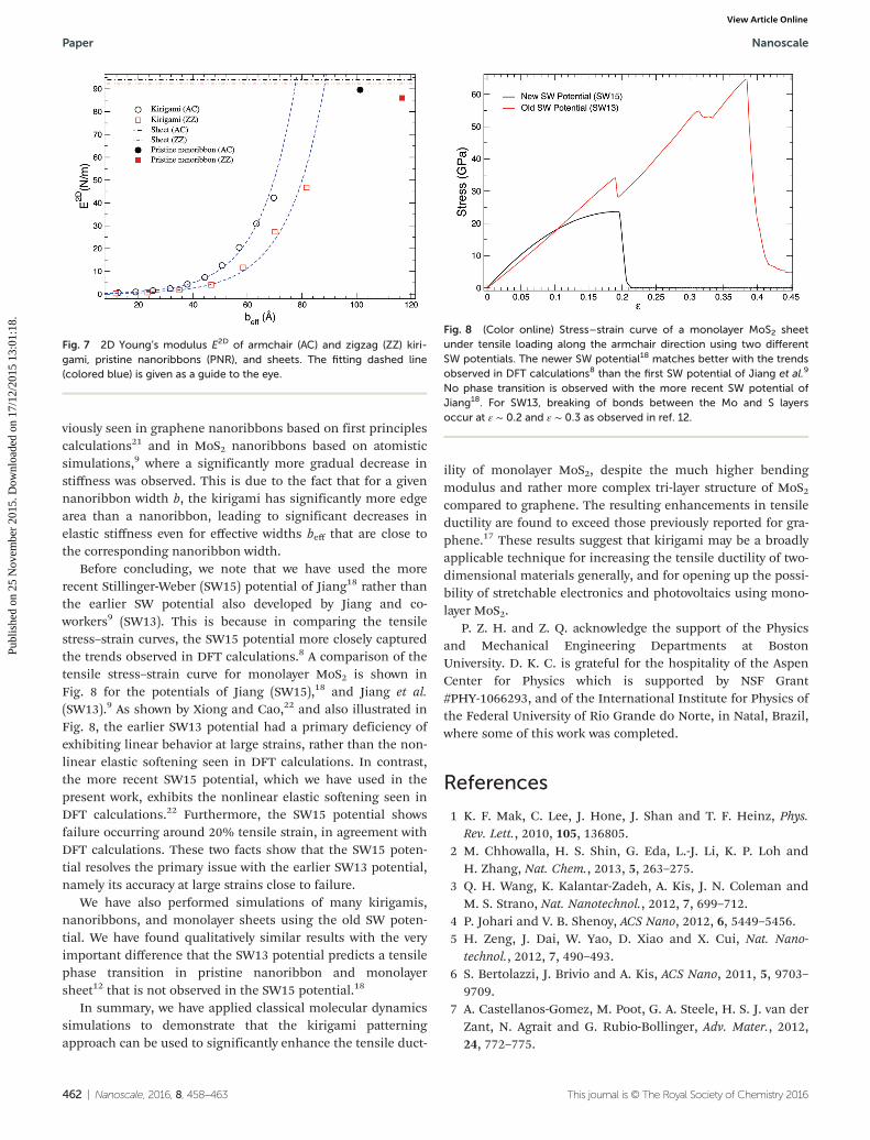
In addition to the yield and fracture behavior, we alsodiscuss the elastic properties, or Young’s modulus. For thekirigami system, we expect the Young’s modulus to decreasewith increasing width of the cut w due to edge effects.9 Fig. 7shows the dependence of Young’s modulus with effectivewidth beff = b − w. As can be seen for both armchair and zigzagorientations, the modulus decreases nonlinearly with decreas-ing effective width, reaching a value that is nearly 200 timessmaller than the corresponding bulk value for the smallesteffective width value we examined. We introduce beff to have amore direct way of comparing the width of nanoribbons andkirigamis. This effective width beff is approximately pro-portional to the number of atoms in one unit cell of ribbonswith cuts (kirigamis) or without cuts (pristine nanoribbons).Furthermore, the trend of the decrease differs from that pre-
Fig. 6 (Color online) Influence of β on the kirigami yield and fracturestrain (a) and stress (b), with constant α = 0.0186 for AC and constantα = 0.0157 for ZZ. Data are normalized by MoS2 nanoribbon results withthe same width.
Fig. 5 (Color online) (a) Influence of α on yield and fracture strain forzigzag (ZZ) and armchair (AC) MoS2 kirigami, with constant β = 0.0375for AC and constant β = 0.0417 for ZZ. (b) Influence of α on yield andfracture stress for zigzag (ZZ) and armchair (AC) MoS2 kirigami. Data arenormalized by MoS2 nanoribbon results with the same width.
viously seen in graphene nanoribbons based on first principlescalculations21 and in MoS2 nanoribbons based on atomisticsimulations,9 where a significantly more gradual decrease instiffness was observed. This is due to the fact that for a givennanoribbon width b, the kirigami has significantly more edgearea than a nanoribbon, leading to significant decreases inelastic stiffness even for effective widths beff that are close tothe corresponding nanoribbon width.
Before concluding, we note that we have used the morerecent Stillinger-Weber (SW15) potential of Jiang18 rather thanthe earlier SW potential also developed by Jiang and co-workers9 (SW13). This is because in comparing the tensilestress–strain curves, the SW15 potential more closely capturedthe trends observed in DFT calculations.8 A comparison of thetensile stress–strain curve for monolayer MoS2 is shown inFig. 8 for the potentials of Jiang (SW15),18 and Jiang et al.(SW13).9 As shown by Xiong and Cao,22 and also illustrated inFig. 8, the earlier SW13 potential had a primary deficiency ofexhibiting linear behavior at large strains, rather than the non-linear elastic softening seen in DFT calculations. In contrast,the more recent SW15 potential, which we have used in thepresent work, exhibits the nonlinear elastic softening seen inDFT calculations.22 Furthermore, the SW15 potential showsfailure occurring around 20% tensile strain, in agreement withDFT calculations. These two facts show that the SW15 poten-tial resolves the primary issue with the earlier SW13 potential,namely its accuracy at large strains close to failure.
We have also performed simulations of many kirigamis,nanoribbons, and monolayer sheets using the old SW poten-tial. We have found qualitatively similar results with the veryimportant difference that the SW13 potential predicts a tensilephase transition in pristine nanoribbon and monolayersheet12 that is not observed in the SW15 potential.18
In summary, we have applied classical molecular dynamicssimulations to demonstrate that the kirigami patterningapproach can be used to significantly enhance the tensile duct-
ility of monolayer MoS2, despite the much higher bendingmodulus and rather more complex tri-layer structure of MoS2compared to graphene. The resulting enhancements in tensileductility are found to exceed those previously reported for gra-phene.17 These results suggest that kirigami may be a broadlyapplicable technique for increasing the tensile ductility of two-dimensional materials generally, and for opening up the possi-bility of stretchable electronics and photovoltaics using mono-layer MoS2.
P. Z. H. and Z. Q. acknowledge the support of the Physicsand Mechanical Engineering Departments at BostonUniversity. D. K. C. is grateful for the hospitality of the AspenCenter for Physics which is supported by NSF Grant#PHY-1066293, and of the International Institute for Physics ofthe Federal University of Rio Grande do Norte, in Natal, Brazil,where some of this work was completed.
References
1 K. F. Mak, C. Lee, J. Hone, J. Shan and T. F. Heinz, Phys.Rev. Lett., 2010, 105, 136805.
2 M. Chhowalla, H. S. Shin, G. Eda, L.-J. Li, K. P. Loh andH. Zhang, Nat. Chem., 2013, 5, 263–275.
3 Q. H. Wang, K. Kalantar-Zadeh, A. Kis, J. N. Coleman andM. S. Strano, Nat. Nanotechnol., 2012, 7, 699–712.
4 P. Johari and V. B. Shenoy, ACS Nano, 2012, 6, 5449–5456.5 H. Zeng, J. Dai, W. Yao, D. Xiao and X. Cui, Nat. Nano-
technol., 2012, 7, 490–493.6 S. Bertolazzi, J. Brivio and A. Kis, ACS Nano, 2011, 5, 9703–
9709.7 A. Castellanos-Gomez, M. Poot, G. A. Steele, H. S. J. van der
Zant, N. Agrait and G. Rubio-Bollinger, Adv. Mater., 2012,24, 772–775.
Fig. 7 2D Young’s modulus E2D of armchair (AC) and zigzag (ZZ) kiri-gami, pristine nanoribbons (PNR), and sheets. The fitting dashed line(colored blue) is given as a guide to the eye.
Fig. 8 (Color online) Stress–strain curve of a monolayer MoS2 sheetunder tensile loading along the armchair direction using two differentSW potentials. The newer SW potential18 matches better with the trendsobserved in DFT calculations8 than the first SW potential of Jiang et al.9
No phase transition is observed with the more recent SW potential ofJiang18. For SW13, breaking of bonds between the Mo and S layersoccur at ε ∼ 0.2 and ε ∼ 0.3 as observed in ref. 12.
8 R. C. Cooper, C. Lee, C. A. Marianetti, X. Wei, J. Hone andJ. W. Kysar, Phys. Rev. B: Condens. Matter, 2013, 87, 035423.
9 J.-W. Jiang, H. S. Park and T. Rabczuk, J. Appl. Phys., 2013,114, 064307.
10 J.-W. Jiang, Z. Qi, H. S. Park and T. Rabczuk, Nanotechno-logy, 2013, 24, 435705.
11 K. Q. Dang, J. P. Simpson and D. E. Spearot, Scr. Mater.,2014, 76, 41–44.
12 J. Zhao, L. Kou, J.-W. Jiang and T. Rabczuk, Nanotechnology,2014, 25, 295701.
13 C. F. Guo, T. Sun, Q. Liu, Z. Suo and Z. Ren, Nat. Commun.,2014, 5, 3121.
14 T. C. Shyu, P. F. Damasceno, P. M. Dodd, A. Lamoureux,L. Xu, M. Shlian, M. Shtein, S. C. Glotzer and N. A. Kotov,Nat. Mater., 2015, 14, 785–789.
15 C. F. Guo, Q. Liu, G. Wang, Y. Wang, Z. Shi, Z. Suo,C.-W. Chu and Z. Ren, Proc. Natl. Acad. Sci. U. S. A., 2015,112, 12332–12337.
16 M. K. Blees, A. W. Barnard, P. A. Rose, S. P. Roberts,K. L. McGill, P. Y. Huang, A. R. Ruyack, J. W. Kevek,B. Kobrin, D. A. Muller, et al., Nature, 2015, 524, 204–207.
17 Z. Qi, D. K. Campbell and H. S. Park, Phys. Rev. B: Condens.Matter, 2014, 90, 245437.
18 J.-W. Jiang, Nanotechnology, 2015, 26, 315706.19 Lammps, http://lammps.sandia.gov, 2012.20 S. Plimpton, J. Comput. Phys., 1995, 117, 1–19.21 P. Wagner, C. P. Ewels, V. V. Ivanovskaya, P. R. Briddon,
A. Pateau and B. Humbert, Phys. Rev. B: Condens. Matter,2011, 84, 134110.
22 S. Xiong and G. Cao, Nanotechnology, 2015, 26, 185705.