73


HIGHWAY DESIGN MANUAL
May 7, 2012
Table of Contents Topic Number
Subject Page Number
i
CHAPTER 10 - DIVISION OF DESIGN
11 Organization and Functions
11.1 Organization 10-1
CHAPTER 20 - DESIGNATION OF HIGHWAY ROUTES
21 Highway Route Numbers
21.1 Legislative Route Numbers and Descriptions 20-1
21.2 Sign Route Numbers 20-1
CHAPTER 40 - FEDERAL-AID
41 Enabling Legislation
41.1 General 40-1
42 Federal-Aid System
42.1 National Highway System 40-1
42.2 Interstate 40-1
43 Federal-Aid Programs
43.1 Surface Transportation Program (STP) 40-1
43.2 California Stewardship & Oversight Agreement with FHWA 40-1
43.3 Congestion Mitigation and Air Quality Improvement Program (CMAQ) 40-2
43.4 Bridge Replacement and Rehabilitation Program 40-2
43.5 Federal Lands Program 40-2
43.6 Highway Safety Improvement Program 40-2
43.7 Special Programs 40-2
44 Funding Determination
44.1 Funding Eligibility 40-2
44.2 Federal Participation Ratio 40-3
44.3 Emergency Relief 40-3
CHAPTER 60 - NOMENCLATURE
61 Abbreviations
61.1 Official Names 60-1
62 Definitions
62.1 Geometric Cross Section 60-1
HIGHWAY DESIGN MANUAL June 21, 2013
Table of Contents Topic Number
Subject Page Number
ii
62.2 Highway Structures 60-2
62.3 Highway Types 60-2
62.4 Interchanges and Intersections at Grade 60-3
62.5 Landscape Architecture 60-6
62.6 Right of Way 60-7
62.7 Pavement 60-8
62.8 Traffic 60-11
62.9 Drainage 60-13
62.10 Users 60-13
CHAPTER 80 - APPLICATION OF DESIGN STANDARDS
81 Project Development Overview
81.1 Philosophy 80-1
81.2 Highway Context 80-1
81.3 Place Types 80-2
81.4 Type of Highway 80-4
81.5 Access Control 80-5
81.6 Design Standards and Highway Context 80-5
82 Application of Standards
82.1 Highway Design Manual Standards 80-5
82.2 Approvals for Nonstandard Design 80-7
82.3 Use of FHWA and AASHTO Standards and Policies 80-7
82.4 Mandatory Procedural Requirements 80-8
82.5 Effective Date for Implementing Revisions to Design Standards 80-8
82.6 Design Information Bulletins and Other Guidance 80-8
82-7 Traffic Engineering 80-8
CHAPTER 100 - BASIC DESIGN POLICIES
101 Design Speed
101.1 Selection of Highway Design Speed 100-1
101.2 Highway Design Speed Standards 100-2
102 Highway Capacity & Level of Service
102.1 Design Capacity (Automobiles) 100-3

HIGHWAY DESIGN MANUAL
May 7, 2012
Table of Contents Topic Number
Subject Page Number
iii
102.2 Design Capacity and Quality of Service (Pedestrians and Bicycles) 100-3
103 Design Designation
103.1 Relation to Design 100-3
103.2 Design Period 100-4
104 Control of Access
104.1 General Policy 100-4
104.2 Access Openings 100-4
104.3 Frontage Roads 100-5
104.4 Protection of Access Rights 100-5
104.5 Relation of Access Opening to a Median Opening 100-5
104.6 Maintaining Local Community Access 100-6
104.7 Cross References 100-6
105 Pedestrian Facilities
105.1 General Policy 100-6
105.2 Sidewalks and Walkways 100-6
105.3 Pedestrian Grade Separations 100-7
105.4 Accessibility Requirements 100-8
105.5 Guidelines for the Location and Design of Curb Ramps 100-10
106 Stage Construction and Utilization of Local Roads
106.1 Stage Construction 100-11
106.2 Utilization of Local Roads 100-11
107 Roadside Installations
107.1 Roadway Connections 100-12
107.2 Maintenance and Police Facilities on Freeways 100-12
107.3 Location of Border Inspection Stations 100-13
108 Coordination with Other Agencies
108.1 Divided Nonfreeway Facilities 100-13
108.2 Transit Loading Facilities 100-13
108.3 Commuter and Light Rail Facilities Within State Right of Way 100-16
108.4 Bus Loading Facilities 100-16
108.5 Bus Rapid Transit 100-17
108.6 High-Occupancy Toll and Express Toll Lanes 100-17

HIGHWAY DESIGN MANUAL May 7, 2012
Table of Contents Topic Number
Subject Page Number
iv
108.7 Coordination with the FHWA 100-17
109 Scenic Values in Planning and Design
109.1 Basic Precepts 100-18
109.2 Design Speed 100-18
109.3 Aesthetic Factors 100-18
110 Special Considerations
110.1 Design for Overloaded Material Hauling Equipment 100-19
110.2 Control of Water Pollution 100-20
110.3 Control of Air Pollution 100-24
110.4 Wetlands Protection 100-26
110.5 Control of Noxious Weeds – Exotic and Invasive Species 100-26
110.6 Earthquake Consideration 100-26
110.7 Traffic Control Plans 100-27
110.8 Safety Reviews 100-29
110.9 Value Analysis 100-30
110.10 Proprietary Items 100-30
110.11 Conservation of Materials and Energy 100-31
110.12 Tunnel Safety Orders 100-32
111 Material Sites and Disposal Sites
111.1 General Policy 100-35
111.2 Investigation of Local Materials Sources 100-37
111.3 Materials Information Furnished to Prospective Bidders 100-38
111.4 Materials Arrangements 100-39
111.5 Procedures for Acquisition of Material Sites and Disposal Sites 100-39
111.6 Mandatory Material Sites and Disposal Sites on Federal-aid Projects 100-40
112 Contractor's Yard and Plant Sites
112.1 Policy 100-41
112.2 Locating a Site 100-41
113 Geotechnical Design Report
113.1 Policy 100-41
113.2 Content 100-41
113.3 Submittal and Review 100-41
HIGHWAY DESIGN MANUAL
May 7, 2012
Table of Contents Topic Number
Subject Page Number
v
114 Materials Report
114.1 Policy 100-41
114.2 Requesting Material Report(s) 100-42
114.3 Content 100-42
114.4 Preliminary Materials Report 100-42
114.5 Review and Retention of Records 100-43
115 Designing for Bicycle Traffic
115.1 General 100-43
116 Bicyclists and Pedestrians on Freeways
116.1 General 100-43
CHAPTER 200 - GEOMETRIC DESIGN AND STRUCTURE STANDARDS
201 Sight Distance
201.1 General 200-1
201.2 Passing Sight Distance 200-1
201.3 Stopping Sight Distance 200-2
201.4 Stopping Sight Distance at Grade Crests 200-2
201.5 Stopping Sight Distance at Grade Sags 200-2
201.6 Stopping Sight Distance on Horizontal Curves 200-2
201.7 Decision Sight Distance 200-3
202 Superelevation
202.1 Basic Criteria 200-3
202.2 Standards for Superelevation 200-4
202.3 Restrictive Conditions 200-4
202.4 Axis of Rotation 200-9
202.5 Superelevation Transition 200-9
202.6 Superelevation of Compound Curves 200-12
202.7 Superelevation on City Streets and County Roads 200-12
203 Horizontal Alignment
203.1 General Controls 200-12
203.2 Standards for Curvature 200-16
203.3 Alignment Consistency 200-16
HIGHWAY DESIGN MANUAL May 7, 2012
Table of Contents Topic Number
Subject Page Number
vi
203.4 Curve Length and Central Angle 200-16
203.5 Compound Curves 200-16
203.6 Reversing Curves 200-17
203.7 Broken Back Curves 200-17
203.8 Spiral Transition 200-17
203.9 Alignment at Bridges 200-17
204 Grade
204.1 General Controls 200-17
204.2 Position with Respect to Cross Section 200-18
204.3 Standards for Grade 200-18
204.4 Vertical Curves 200-18
204.5 Sustained Grades 200-19
204.6 Coordination of Horizontal and Vertical Alignment 200-22
204.7 Separate Grade Lines 200-22
204.8 Grade Line of Structures 200-22
205 Road Connections and Driveways
205.1 Access Openings on Expressways 200-25
205.2 Private Road Connections 200-26
205.3 Urban Driveways 200-26
205.4 Driveways on Frontage Roads and in Rural Areas 200-27
205.5 Financial Responsibility 200-28
206 Pavement Transitions
206.1 General Transition Standards 200-28
206.2 Pavement Widenings 200-28
206.3 Pavement Reductions 200-28
206.4 Temporary Freeway Transitions 200-30
207 Airway-Highway Clearances
207.1 Introduction 200-30
207.2 Clearances 200-30
207.3 Submittal of Airway-Highway Clearance Data 200-30
208 Bridges, Grade Separation Structures, and Structure Approach Embankment
208.1 Bridge Lane and Shoulder Width 200-35
HIGHWAY DESIGN MANUAL
November 2, 2012
Table of Contents Topic Number
Subject Page Number
vii
208.2 Cross Slope 200-35
208.3 Median 200-35
208.4 Bridge Sidewalks 200-37
208.5 Open End Structures 200-37
208.6 Bicycle and Pedestrian Overcrossings and Undercrossings 200-37
208.7 Equestrian Undercrossings and Overcrossings 200-37
208.8 Cattle Passes, Equipment, and Deer Crossings 200-37
208.9 Railroad Underpasses and Overheads 200-38
208.10 Bridge Barriers and Railings 200-38
208.11 Structure Approach Embankment 200-40
209 Currently Not In Use
210 Reinforced Earth Slopes and Earth Retaining Systems
210.1 Introduction 200-46
210.2 Construction Methods and Types 200-46
210.3 Alternative Earth Retaining Systems (AERS) 200-52
210.4 Cost Reduction Incentive Proposals (CRIP) 200-53
210.5 Aesthetic Consideration 200-53
210.6 Safety Railing, Fences, and Concrete Barriers 200-54
210.7 Design Responsibility 200-54
210.8 Guidelines for Type Selection and Plan Preparation 200-55
CHAPTER 300 – GEOMETRIC CROSS SECTION
301 Traveled Way Standards
301.1 Lane Width 300-1
301.2 Class II Bikeway (Bike Lane) Lane Width 300-1
301.3 Cross Slopes 300-2
302 Highway Shoulder Standards
302.1 Width 300-3
302.2 Cross Slopes 300-3
302.3 Safety Edge 300-6
303 Curbs, Dikes, and Side Gutters
303.1 General Policy 300-6

HIGHWAY DESIGN MANUAL November 2, 2012
Table of Contents Topic Number
Subject Page Number
viii
303.2 Curb Types and Uses 300-7
303.3 Dike Types and Uses 300-9
303.4 Curb Extensions 300-11
303.5 Position of Curbs and Dikes 300-11
303.6 Curbs and Dikes on Frontage Roads and Streets 300-13
304 Side Slopes
304.1 Side Slope Standards 300-13
304.2 Clearance From Slope to Right of Way Line 300-14
304.3 Slope Benches and Cut Widening 300-14
304.4 Contour Grading and Slope Rounding 300-15
304.5 Stepped Slopes 300-15
305 Median Standards
305.1 Width 300-16
305.2 Median Cross Slopes 300-17
305.3 Median Barriers 300-17
305.4 Median Curbs 300-17
305.5 Paved Medians 300-17
305.6 Separate Roadways 300-18
306 Right of Way
306.1 General Standards 300-18
306.2 Right of Way Through the Public Domain 300-18
307 Cross Sections for State Highways
307.1 Cross Section Selection 300-18
307.2 Two-lane Cross Sections for New Construction 300-18
307.3 Two-lane Cross Sections for 2R, 3R, and other Projects 300-20
307.4 Multilane Divided Cross Sections 300-20
307.5 Multilane All Paved Cross Sections with Special Median Widths 300-20
307.6 Multilane Cross Sections for 2R and 3R Projects 300-24
307.7 Reconstruction Projects 300-24
308 Cross Sections for Roads Under Other Jurisdictions
308.1 City Streets and County Roads 300-24
HIGHWAY DESIGN MANUAL
November 2, 2012
Table of Contents Topic Number
Subject Page Number
ix
309 Clearances
309.1 Horizontal Clearances for Highways 300-25
309.2 Vertical Clearances 300-27
309.3 Tunnel Clearances 300-32
309.4 Lateral Clearance for Elevated Structures 300-32
309.5 Structures Across or Adjacent to Railroads 300-32
310 Frontage Roads
310.1 Cross Section 300-33
310.2 Outer Separation 300-34
310.3 Headlight Glare 300-34
CHAPTER 400 – INTERSECTIONS AT GRADE
401 Factors Affecting Design
401.1 General 400-1
401.2 Human Factors 400-1
401.3 Traffic Considerations 400-2
401.4 The Physical Environment 400-2
401.5 Intersection Type 400-2
401.6 Transit 400-3
402 Operational Features Affecting Design
402.1 Capacity 400-3
402.2 Collisions 400-3
402.3 On-Street Parking 400-4
402.4 Consider All Users 400-4
402.5 Speed-Change Areas 400-4
403 Principles of Channelization
403.1 Preference to Major Movements 400-4
403.2 Areas of Conflict 400-4
403.3 Angle of Intersection 400-5
403.4 Points of Conflict 400-5
403.5 Currently Not In Use 400-6
403.6 Turning Traffic 400-6

HIGHWAY DESIGN MANUAL November 2, 2012
Table of Contents Topic Number
Subject Page Number
x
403.7 Refuge Areas 400-9
403.8 Prohibited Turns 400-9
403.9 Effective Signal Control 400-9
403.10 Installation of Traffic Control Devices 400-9
403.11 Summary 400-9
403.12 Other Considerations 400-10
404 Design Vehicles
404.1 General 400-10
404.2 Design Considerations 400-10
404.3 Design Tools 400-11
404.4 Design Vehicles and Related Definitions 400-12
404.5 Turning Templates & Vehicle Diagrams 400-13
405 Intersection Design Standards
405.1 Sight Distance 400-14
405.2 Left-turn Channelization 400-23
405.3 Right-turn Channelization 400-25
405.4 Traffic Islands 400-29
405.5 Median Openings 400-30
405.6 Access Control 400-32
405.7 Public Road Intersections 400-34
405.8 City Street Returns and Corner Radii 400-34
405.9 Widening of 2-lane Roads at Signalized Intersections 400-34
406 Ramp Intersection Capacity Analysis 400-36
CHAPTER 500 – TRAFFIC INTERCHANGES
501 General
501.1 Concepts 500-1
501.2 Warrants 500-1
501.3 Spacing 500-1
502 Interchange Types
502.1 General 500-1
502.2 Local Street Interchanges 500-2

HIGHWAY DESIGN MANUAL
November 2, 2012
Table of Contents Topic Number
Subject Page Number
xi
502.3 Freeway-to-freeway Interchanges 500-6
503 Interchange Design Procedure
503.1 Basic Data 500-8
503.2 Reviews 500-8
504 Interchange Design Standards
504.1 General 500-11
504.2 Freeway Entrances and Exits 500-11
504.3 Ramps 500-15
504.4 Freeway-to-Freeway Connections 500-35
504.5 Auxiliary Lanes 500-36
504.6 Mainline Lane Reduction at Interchanges 500-36
504.7 Weaving Sections 500-38
504.8 Access Control 500-39
CHAPTERS 600 – 670 – PAVEMENT ENGINEERING CHAPTER 600 – GENERAL ASPECTS
601 Introduction 600-1
602 Pavement Structure Layers
602.1 Description 600-1
603 Types of Pavement Projects
603.1 New Construction 600-3
603.2 Widening 600-3
603.3 Pavement Preservation 600-3
603.4 Roadway Rehabilitation 600-6
603.5 Reconstruction 600-6
603.6 Temporary Pavements and Detours 600-7
604 Roles and Responsibilities
604.1 Roles and Responsibilities for Pavement Engineering 600-7
604.2 Other Resources 600-8
605 Record Keeping
605.1 Documentation 600-9
605.2 Subsequent Revisions 600-10

HIGHWAY DESIGN MANUAL November 2, 2012
Table of Contents Topic Number
Subject Page Number
xii
606 Research and Special Designs
606.1 Research and Experimentation 600-10
606.2 Special Designs 600-10
606.3 Mechanistic-Emperical Design 600-10
606.4 Proprietary Items 600-11
CHAPTER 610 – PAVEMENT ENGINEERING CONSIDERATIONS
611 Factors in Selecting Pavement Types
611.1 Pavement Type Selection 610-1
611.2 Selection Criteria 610-1
612 Pavement Design Life
612.1 Definition 610-1
612.2 New Construction and Reconstruction 610-1
612.3 Widening 610-1
612.4 Pavement Preservation 610-3
612.5 Roadway Rehabilitation 610-3
612.6 Temporary Pavements and Detours 610-3
612.7 Non-Structural Wearing Courses 610-3
613 Traffic Considerations
613.1 Overview 610-3
613.2 Traffic Volume Projection 610-4
613.3 Traffic Index Calculation 610-5
613.4 Axle Load Spectra 610-5
613.5 Specific Traffic Loading Considerations 610-8
614 Soil Characteristics
614.1 Engineering Considerations 610-11
614.2 Unified Soil Classification System (USCS) 610-12
614.3 California R-Value 610-12
614.4 Expansive Soils 610-14
614.5 Subgrade Enhancement Geotextile (SEG) 610-15
614.6 Other Considerations 610-15
615 Climate 610-16

HIGHWAY DESIGN MANUAL
November 2, 2012
Table of Contents Topic Number
Subject Page Number
xiii
616 Existing Pavement Type and Condition 610-18
617 Materials
617.1 Availability of Materials 610-18
617.2 Recycling 610-18
618 Maintainability and Constructibility
618.1 Maintainability 610-19
618.2 Constructibility 610-19
619 Life-Cycle Cost Analysis
619.1 Life-Cycle Cost Analysis 610-20
CHAPTER 620 – RIGID PAVEMENT
621 Types of Rigid Pavements
621.1 Jointed Plain Concrete Pavement (JPCP) 620-1
621.2 Continuously Reinforced Concrete Pavement (CRCP) 620-1
621.3 Precast Panel Concrete Pavement (PPCP) 620-1
622 Engineering Requirements
622.1 Engineering Properties 620-1
622.2 Performance Factors 620-3
622.3 Pavement Joints 620-3
622.4 Dowel Bars and Tie Bars 620-3
622.5 Joint Seals 620-5
622.6 Bond Breaker 620-5
622.7 Texturing 620-6
622.8 Transitions and Anchors 620-6
623 Engineering Procedure for New and Reconstruction Projects
623.1 Catalog 620-6
623.2 Mechanistic-Emperical Method 620-21
624 Engineering Procedures for Pavement Preservation
624.1 Preventive Maintenance 620-21
624.2 Capital Preventive Maintenance (CAPM) 620-21
625 Engineering Procedures for Pavement and Roadway Rehabilitation
625.1 Rigid Pavement Rehabilitation Strategies 620-21

HIGHWAY DESIGN MANUAL November 2, 2012
Table of Contents Topic Number
Subject Page Number
xiv
625.2 Mechanistic-Emperical Method 620-22
626 Other Considerations
626.1 Traveled Way 620-22
626.2 Shoulder 620-24
626.3 Intersections 620-27
626.4 Roadside Facilities 620-27
CHAPTER 630 – FLEXIBLE PAVEMENT
631 Types of Flexible Pavements & Materials
631.1 Hot Mix Asphalt (HMA) 630-1
631.2 Open Graded Friction Course (OGFC) 630-1
631.3 Rubberized Hot Mix Asphalt (RHMA) 630-1
631.4 Other Types of Flexible Pavement 630-2
631.5 Stress Absorbing Membrane Interlayers (SAMI) 630-2
632 Engineering Criteria
632.1 Engineering Properties 630-2
632.2 Performance Factors 630-3
633 Engineering Procedures for New and Reconstruction Projects
633.1 Emperical Method 630-5
633.2 Mechanistic-Emperical Method 630-9
634 Engineering Procedures for Flexible Pavement Preservation
634.1 Preventive Maintenance 630-9
634.2 Capital Preventive Maintenance (CAPM) 630-9
635 Engineering Procedures for Flexible Pavement and Roadway Rehabilitation
635.1 Emperical Method 630-9
635.2 Mechanistic-Emperical Method 630-19
636 Other Considerations
636.1 Traveled Way 630-19
636.2 Shoulders 630-20
636.3 Intersections 630-20
636.4 Roadside Facilities 630-20
637 Engineering Analysis Software 630-21

HIGHWAY DESIGN MANUAL
May 7, 2012
Table of Contents Topic Number
Subject Page Number
xv
CHAPTER 640 – COMPOSITE PAVEMENTS
641 Types of Composite Pavement
641.1 Flexible Over Rigid Layer 640-1
641.2 Rigid Over Flexible Layer 640-1
642 Engineering Criteria
642.1 Engineering Properties 640-1
642.2 Performance Factors 640-1
643 Engineering Procedures for New Construction and Reconstruction
643.1 Emperical Method 640-2
643.2 Mechanistic-Emperical Method 640-2
644 Engineering Procedures for Pavement Preservation
644.1 Preventive Maintenance 640-2
644.2 Capital Preventive Maintenance (CAPM) 640-2
645 Engineering Procedures for Pavement and Roadway Rehabilitation
645.1 Emperical Method 640-3
645.2 Mechanistic-Emperical Method 640-3
CHAPTER 650 – PAVEMENT DRAINAGE
651 General Considerations
651.1 Impacts of Drainage on Pavement 650-1
651.2 Drainage System Components and Requirements 650-1
652 Storm Water Management 650-6
653 Other Considerations
653.1 New Consideration Projects 650-6
653.2 Widening Projects 650-6
653.3 Rehabilitation and Reconstruction Projects 650-6
653.4 Ramps 650-6
653.5 Roadside Facilities 650-6
CHAPTER 660 – BASE AND SUBBASE
661 Engineering Considerations 660-1

HIGHWAY DESIGN MANUAL June 21, 2013
Table of Contents Topic Number
Subject Page Number
xvi
662 Base and Subbase Categories
662.1 Aggregate Base and Subbase 660-1
662.2 Treated Base and Subbase 660-1
662.3 Treated Permeable Base and Subbase 660-1
663 Engineering Criteria 660-2
CHAPTER 670 – STRUCTURE APPROACH SLABS
671 Application
671.1 Purpose 670-1
671.2 Application 670-1
672 General Considerations
672.1 Field Investigations 670-1
672.2 Load Transfer at Approach Slab/Concrete Pavement Joint 670-1
672.3 Guardrails 670-3
672.4 Barriers 670-3
672.5 Structural Approach System Drainage 670-3
673 Structure Approach Slab Rehabilitation Considerations
673.1 Approach Slab Replacement 670-3
673.2 Structure Approach Slab Drainage 670-3
673.3 Pavement Details 670-4
673.4 Traffic Handling 670-4
CHAPTER 700 – MISCELLANEOUS STANDARDS
701 Fences
701.1 Type, Intent and Purpose of Fences 700-1
701.2 Freeway and Expressway Access Control Fence 700-2
701.3 Private Fences 700-3
701.4 Temporary Fences 700-4
701.5 Other Fences 700-4
702 Miscellaneous Traffic Items
702.1 References 700-4
703 Special Structures and Installation
703.1 Truck Weighing Facilities 700-4

HIGHWAY DESIGN MANUAL
June 21, 2013
Table of Contents Topic Number
Subject Page Number
xvii
703.2 Rockfall Restraining Nets 700-4
704 Contrast Treatment
704.1 Policy 700-5
705 Materials and Color Selection
705.1 Special Treatments and Materials 700-5
705.2 Colors for Steel Structures 700-5
706 Roadside Treatment
706.1 Roadside Management 700-5
706.2 Vegetation Control 700-7
706.3 Topsoil 700-7
706.4 Irrigation Crossovers for Highway Construction Projects 700-7
706.5 Water Supply Line (Bridge) and Sprinkler Control Conduit for Bridge 700-7
706.6 Water Supply for Future Roadside Rest Areas, Vista Points, or Planting 700-8
707 Slope Treatment Under Structures
707.1 Policy 700-8
707.2 Guidelines for Slope Treatment 700-8
707.3 Procedure 700-8
CHAPTERS 800-890 – HIGHWAY DRAINAGE DESIGN CHAPTERS 800 – GENERAL ASPECTS
801 General
801.1 Introduction 800-1
801.2 Drainage Design Philosophy 800-1
801.3 Drainage Standards 800-1
801.4 Objectives of Drainage Design 800-2
801.5 Economics of Design 800-2
801.6 Use of Drainage References 800-3
802 Drainage Design Responsibilities
802.1 Functional Organization 800-3
802.2 Culvert Committee 800-5
802.3 Bank and Shore Protection Committee 800-5
HIGHWAY DESIGN MANUAL June 21, 2013
Table of Contents Topic Number
Subject Page Number
xviii
803 Drainage Design Policies
803.1 Basic Policy 800-6
803.2 Cooperative Agreements 800-6
803.3 Up-Grading Existing Drainage Facilities 800-6
804 Floodplain Encroachments
804.1 Purpose 800-7
804.2 Authority 800-7
804.3 Applicability 800-7
804.4 Definitions 800-7
804.5 Procedures 800-8
804.6 Responsibilities 800-8
804.7 Preliminary Evaluation of Risks and Impacts for Environmental Document Phase
800-9
804.8 Design Standards 800-10
804.9 Coordination with the Local Community 800-10
804.10 National Flood Insurance Program 800-10
804.11 Coordination with FEMA 800-14
805 Preliminary Plans
805.1 Required FHWA Approval 800-14
805.2 Bridge Preliminary Report 800-14
805.3 Storm Drain Systems 800-15
805.4 Unusual Hydraulic Structures 800-15
805.5 Levees and Dams Formed by Highway Fills 800-15
805.6 Geotechnical 800-15
805.7 Data Provided by the District 800-15
806 Definitions of Drainage Terms
806.1 Introduction 800-16
806.2 Drainage Terms 800-16
807 Selected Drainage References
807.1 Introduction 800-35
807.2 Federal Highway Administration Hydraulic Publications 800-35
HIGHWAY DESIGN MANUAL
June 21, 2013
Table of Contents Topic Number
Subject Page Number
xix
807.3 American Association of State Highway and Transportation Officials (AASHTO)
800-37
807.4 California Department of Transportation 800-37
807.5 U.S. Department of Interior – Geological Survey (USGS) 800-37
807.6 U.S. Department of Agriculture – Natural Resources Conservation Service (NRCS)
800-37
807.7 California Department of Water Resources and Caltrans 800-37
807.8 University of California – Institute of Transportation and Traffic Engineering (ITTE)
800-38
807.9 U.S. Army Corps of Engineers 800-38
808 Selected Computer Programs 800-38
CHAPTER 810 – HYDROLOGY
811 General
811.1 Introduction 810-1
811.2 Objectives of Hydrologic Analysis 810-1
811.3 Peak Discharge 810-1
811.4 Flood Severity 810-2
811.5 Factors Affecting Runoff 810-2
812 Basin Characteristics
812.1 Size 810-2
812.2 Shape 810-2
812.3 Slope 810-2
812.4 Land Use 810-2
812.5 Soil and Geology 810-3
812.6 Storage 810-3
812.7 Elevation 810-3
812.8 Orientation 810-3
813 Channel and Floodplain Characteristics
813.1 General 810-4
813.2 Length and Slope 810-4
813.3 Cross Section 810-4
813.4 Hydraulic Roughness 810-4

HIGHWAY DESIGN MANUAL June 21, 2013
Table of Contents Topic Number
Subject Page Number
xx
813.5 Natural and Man-made Constrictions 810-4
813.6 Channel Modifications 810-4
813.7 Aggradation – Degradation 810-4
813.8 Debris 810-5
814 Meteorological Characteristics
814.1 General 810-5
814.2 Rainfall 810-5
814.3 Snow 810-5
814.4 Evapo-transpiration 810-6
814.5 Tides and Waves 810-6
815 Hydrologic Data
815.1 General 810-6
815.2 Categories 810-7
815.3 Sources 810-7
815.4 Stream Flow 810-8
815.5 Rainfall 810-8
815.6 Adequacy of Data 810-8
816 Runoff
816.1 General 810-8
816.2 Overland Flow 810-9
816.3 Subsurface Flow 810-9
816.4 Detention and Retention 810-9
816.5 Flood Hydrograph and Flood Volume 810-9
816.6 Time of Concentration (Tc) and Travel Time (Tt) 810-9
817 Flood Magnitude
817.1 General 810-12
817.2 Measurements 810-12
818 Flood Probability and Frequency
818.1 General 810-12
818.2 Establishing Design Flood Frequency 810-14
819 Estimating Design Discharge
819.1 Introduction 810-15
HIGHWAY DESIGN MANUAL
June 21, 2013
Table of Contents Topic Number
Subject Page Number
xxi
819.2 Empirical Methods 810-15
819.3 Statistical Methods 810-19
819.4 Hydrograph Methods 810-21
819.5 Transfer of Data 810-21
819.6 Hydrologic Computer Programs 810-21
819.7 Region-Specific Analysis 810-23
CHAPTER 820 – CROSS DRAINAGE
821 General
821.1 Introduction 820-1
821.2 Hydrologic Considerations 820-1
821.3 Selection of Design Flood 820-2
821.4 Headwater and Tailwater 820-2
821.5 Effects of Tide and Wind 820-3
822 Debris Control
822.1 Introduction 820-3
822.2 Debris Control Methods 820-3
822.3 Economics 820-4
822.4 Classification of Debris 820-4
822.5 Types of Debris Control Structures 820-4
823 Culvert Location
823.1 Introduction 820-4
823.2 Alignment and Slope 820-4
824 Culvert Type Selection
824.1 Introduction 820-5
824.2 Shape and Cross Section 820-5
825 Hydraulic Design of Culverts
825.1 Introduction 820-5
825.2 Culvert Flow 820-5
825.3 Computer Programs 820-6
825.4 Coefficient of Roughness 820-6

HIGHWAY DESIGN MANUAL June 21, 2013
Table of Contents Topic Number
Subject Page Number
xxii
826 Entrance Design
826.1 Introduction 820-6
826.2 End Treatment Policy 820-6
826.3 Conventional Entrance Designs 820-7
826.4 Improved Inlet Designs 820-7
827 Outlet Design
827.1 General 820-8
827.2 Embankment Protection 820-8
828 Diameter and Length
828.1 Introduction 820-9
828.2 Minimum Diameter 820-9
828.3 Length 820-9
829 Special Considerations
829.1 Introduction 820-10
829.2 Bedding and Backfill 820-10
829.3 Piping 820-11
829.4 Joints 820-11
829.5 Anchorage 820-11
829.6 Irregular Treatment 820-12
829.7 Siphons and Sag Culverts 820-12
829.8 Currently Not In Use 820-12
829.9 Dams 820-12
829.10 Reinforced Concrete Box Modifications 820-13
CHAPTER 830 – TRANSPORTATION FACILITY DRAINAGE
831 General
831.1 Basic Concepts 830-1
831.2 Highway Grade Line 830-1
831.3 Design Storm and Water Spread 830-1
831.4 Other Considerations 830-2
831.5 Computer Programs 830-5

HIGHWAY DESIGN MANUAL
June 21, 2013
Table of Contents Topic Number
Subject Page Number
xxiii
832 Hydrology
832.1 Introduction 830-5
832.2 Rational Method 830-5
832.3 Time of Concentration 830-5
833 Roadway Cross Sections
833.1 Introduction 830-5
833.2 Grade, Cross Slope, and Superelevation 830-5
834 Roadside Drainage
834.1 General 830-6
834.2 Median Drainage 830-6
834.3 Ditches and Gutters 830-6
834.4 Overside Drains 830-7
835 Dikes and Berms
835.1 General 830-8
835.2 Earth Berms 830-8
835.3 Dikes 830-9
836 Curbs and Gutters
836.1 General 830-9
836.2 Gutter Design 830-9
837 Inlet Design
837.1 General 830-9
837.2 Inlet Types 830-10
837.3 Location and Spacing 830-14
837.4 Hydraulic Design 830-15
837.5 Local Depressions 830-16
838 Storm Drains
838.1 General 830-17
838.2 Design Criteria 830-17
838.3 Hydraulic Design 830-17
838.4 Standards 830-18
838.5 Appurtenant Structures 830-19

HIGHWAY DESIGN MANUAL June 21, 2013
Table of Contents Topic Number
Subject Page Number
xxiv
839 Pumping Stations
839.1 General 830-20
839.2 Pump Type 830-20
839.3 Design Responsibilities 830-20
839.4 Trash and Debris Considerations 830-20
839.5 Maintenance Consideration 830-21
839.6 Groundwater Considerations 830-21
CHAPTER 840 – SUBSURFACE DRAINAGE
841 General
841.1 Introduction 840-1
841.2 Subsurface (Groundwater) Discharge 840-1
841.3 Preliminary Investigations 840-1
841.4 Exploration Notes 840-1
841.5 Category of System 840-2
842 Pipe Underdrains
842.1 General 840-3
842.2 Single Installations 840-3
842.3 Multiple Installations 840-3
842.4 Design Criteria 840-3
842.5 Types of Underdrain Pipe 840-4
842.6 Design Service Life 840-4
842.7 Pipe Selection 840-5
CHAPTER 850 – PHYSICAL STANDARDS
851 General
851.1 Introduction 850-1
851.2 Selection of Material and Type 850-1
852 Pipe Materials
852.1 Reinforced Concrete Pipe (RCP) 850-1
852.2 Concrete Box and Arch Culverts 850-3
852.3 Corrugated Steel Pipe, Steel Spiral Rib Pipe and Pipe Arches 850-3
852.4 Corrugated Aluminum Pipe, Aluminum Spiral Rib Pipe and Pipe Arches 850-6
HIGHWAY DESIGN MANUAL
June 21, 2013
Table of Contents Topic Number
Subject Page Number
xxv
852.5 Structural Metal Plate 850-8
852.6 Plastic Pipe 850-9
852.7 Special Purpose Types 850-10
853 Pipe Liners and Linings for Culvert Rehabilitation
853.1 General 850-10
853.2 Caltrans Host Pipe Structural Philosophy 850-10
853.3 Problem Identification and Coordination 850-11
853.4 Alternative Pipe Liner Materials 850-11
853.5 Cementitious Pipe Lining 850-12
853.6 Invert Paving with Concrete 850-12
853.7 Structural Repairs with Steel Tunnel Liner Plate 850-14
854 Pipe Connections
854.1 Basic Policy 850-14
855 Design Service Life
855.1 Basic Concepts 850-17
855.2 Abrasion 850-19
855.3 Corrosion 850-30
855.4 Protection of Concrete Pipe and Drainage Structures from Acids, Chlorides and Sulfates
850-33
855.5 Material Susceptibility to Fire 850-36
856 Height of Fill
856.1 Construction Loads 850-36
856.2 Concrete Pipe, Box and Arch Culverts 850-36
856.3 Metal Pipe and Structural Plate Pipe 850-37
856.4 Plastic Pipe 850-54
856.5 Minimum Height of Cover 850-55
857 Alternative Materials
857.1 Basic Policy 850-55
857.2 Alternative Pipe Culvert Selection Procedure Using AltPipe 850-55
857.3 Alternative Pipe Culvert (APC) and Pipe Arch Culvert List 850-59

HIGHWAY DESIGN MANUAL June 21, 2013
Table of Contents Topic Number
Subject Page Number
xxvi
CHAPTER 860 – OPEN CHANNELS
861 General
861.1 Introduction 860-1
861.2 Hydraulic Considerations 860-1
861.3 Selection of “Design Flood” 860-1
861.4 Safety Considerations 860-2
861.5 Maintenance Consideration 860-2
861.6 Economics 860-2
861.7 Coordination with Other Agencies 860-2
861.8 Environment 860-2
861.9 References 860-3
862 Channel Location
862.1 General 860-3
862.2 Alignment and Grade 860-3
863 Channel Section
863.1 Natural Channels 860-3
863.2 Triangular V-Ditch 860-5
863.3 Trapezoidal 860-5
863.4 Rectangular 860-5
864 Hydraulic Design of Channels
864.1 General 860-5
864.2 Flow Classifications 860-5
864.3 Open Channel Flow Equations 860-6
864.4 Water Surface Profiles 860-9
864.5 Stage-Discharge Relationships 860-10
865 Channel Changes
865.1 General 860-10
865.2 Design Considerations 860-11
866 Freeboard Considerations
866.1 General 860-11
866.2 Height of Freeboard 860-11

HIGHWAY DESIGN MANUAL
June 21, 2013
Table of Contents Topic Number
Subject Page Number
xxvii
CHAPTER 870 – CHANNEL AND SHORE PROTECTION – EROSION CONTROL
871 General
871.1 Introduction 870-1
871.2 Design Philosophy 870-1
871.3 Selected References 870-2
872 Planning and Location Studies
872.1 Planning 870-3
872.2 Class and Type of Protection 870-4
872.3 Site Consideration 870-4
872.4 Data Needs 870-12
873 Design Concepts
873.1 Introduction 870-12
873.2 Design High Water and Hydraulics 870-13
873.3 Armor Protection 870-19
873.4 Training Systems 870-41
873.5 Design Check List 870-50
CHAPTER 880 – CURRENTLY NOT IN USE
CHAPTER 890 – STORM WATER MANAGEMENT
891 General
891.1 Introduction 890-1
891.2 Philosophy 890-1
892 Storm Water Management Strategies
892.1 General 890-1
892.2 Types of Strategies 890-1
892.3 Design Considerations 890-2
892.4 Mixing with Other Waste Streams 890-2
893 Maintenance Requirements for Storm Water Management Features
893.1 General 890-3

HIGHWAY DESIGN MANUAL June 21, 2013
Table of Contents Topic Number
Subject Page Number
xxviii
CHAPTER 900 – LANDSCAPE ARCHITECTURE
901 General
901.1 Landscape Architecture Program 900-1
901.2 Cross References 900-1
902 Highway Planting Standards and Guidelines
902.1 General 900-1
902.2 Sight Distance and Clear Recovery Zone Standards 900-3
902.3 Planting Guidelines 900-4
902.4 Irrigation Guidelines 900-7
903 Safety Roadside Rest Area Standards and Guidelines
903.1 Minimum Standards 900-8
903.2 General 900-8
903.3 Site Selection 900-9
903.4 Facility Size and Capacity Analysis 900-9
903.5 Site Planning 900-11
903.6 Utility Systems 900-14
903.7 Structures 900-16
903.8 Security and Pedestrian Amenities 900-17
904 Vista Point Standards and Guidelines
904.1 General 900-17
904.2 Site Selection 900-18
904.3 Design Features and Facilities 900-18
905 Park and Ride Standards and Guidelines
905.1 General 900-19
905.2 Site Selection 900-19
905.3 Design Features and Facilities 900-20
CHAPTER 1000 – BICYCLE TRANSPORTATION DESIGN
1001 Introduction
1001.1 Bicycle Transportation 1000-1
1001.2 Streets and Highways Code References 1000-1
1001.3 Vehicle Code References 1000-1

HIGHWAY DESIGN MANUAL
June 21, 2013
Table of Contents Topic Number
Subject Page Number
xxix
1001.4 Bikeways 1000-1
1002 Bikeway Facilties
1002.1 Selection of the Type of Facility 1000-2
1003 Bikeway Design Criteria
1003.1 Class I Bikeways (Bike Paths) 1000-3
1003.2 Class II Bikeways (Bike Lanes) 1000-13
1003.3 Class III Bikeways (Bike Routes) 1000-13
1003.4 Trails 1000-14
1003.5 Miscellaneous Criteria 1000-14
CHAPTER 1100 – HIGHWAY TRAFFIC NOISE ABATEMENT
1101 General Requirements
1101.1 Introduction 1100-1
1101.2 Objective 1100-1
1101.3 Terminology 1100-2
1101.4 Procedures for Assessing Noise Impacts 1100-2
1101.5 Prioritizing Construction of Retrofit Noise Barriers 1100-2
1102 Design Criteria
1102.1 General 1100-2
1102.2 Noise Barrier Location 1100-2
1102.3 Noise Barrier Heights 1100-3
1102.4 Noise Barrier Length 1100-4
1102.5 Alternative Noise Barrier Designs 1100-4
1102.6 Noise Barrier Aesthetics 1100-5
1102.7 Maintenance Consideration in Noise Barrier Design 1100-6
1102.8 Emergency Access Considerations in Noise Barrier Design 1100-6
1102.9 Drainage Openings in Noise Barrier 1100-7
HIGHWAY DESIGN MANUAL May 7, 2012
List of Figures Figure Number
Subject Page Number
xxx
CHAPTER 10 – DIVISION OF DESIGN
11.1 Division of Design Functional Organization Chart 10-2
CHAPTER 20 – DESIGNATION OF HIGHWAY ROUTES
21.1 Interstate Highway System in California 20-2
CHAPTER 60 – NOMENCLATURE
62.2 Types of Structures 60-4
CHAPTER 100 – BASIC DESIGN POLICIES
110.12 California Mining and Tunneling Districts 100-36
CHAPTER 200 – GEOMETRIC DESIGN AND STRUCTURE STANDARDS
201.4 Stopping Sight Distance on Crest Vertical Curves 200-5
201.5 Stopping Sight Distance on Sag Vertical Curves 200-6
201.6 Stopping Sight Distance on Horizontal Curves 200-7
201.7 Decision Sight Distance on Crest Vertical Curves 200-8
202.2 Maximum Comfortable Speed on Horizontal Curves 200-11
202.5A Superelevation Transition 200-13
202.5B Superelevation Transition Terms & Definitions 200-14
202.6 Superelevation of Compound Curves 200-15
204.4 Vertical Curves 200-20
204.5 Critical Lengths of Grade for Design 200-21
205.1 Access Openings on Expressways 200-26
206.2 Typical Two-lane to Four-lane Transitions 200-29
207.2A Airway-Highway Clearance Requirements (Civil Airports) 200-31
207.2B Airway-Highway Clearance Requirements (Heliport) 200-32
207.2C Airway-Highway Clearance Requirements (Military Airports) 200-33
207.2D Airway-Highway Clearance Requirements (Navy Carrier Landing Practice Field) 200-34
208.1 Offsets to Safety-Shape Barriers 200-36
208.10A Vehicular Railings for Bridge Structures 200-41
208.10B Combination Vehicular Barrier and Pedestrian Railings for Bridge Structures 200-42
208.10C Pedestrian Railings for Bridge Structures 200-43
208.11A Limits of Structure Approach Embankment Material 200-44

HIGHWAY DESIGN MANUAL
May 7, 2012
List of Figures Figure Number
Subject Page Number
xxxi
208.11B Abutment Drainage Details 200-45
210.8 Type Selection and PS&E Process for Reinforced Earth Slopes and Earth Retaining Systems
200-58
CHAPTER 300 – GEOMETRIC CROSS SECTION
301.2A Typical Class II Bikeway (Bike Lane) Cross Section 300-5
303.3 Dike Type Selection and Placement 300-10
303.4 Bulbout with and without Class II Bike Lane 300-12
305.6 Optional Median Designs for Freeways with Separate Roadways 300-19
307.2 Geometric Cross Sections for Two-lane Highways (New Construction) 300-21
307.4 Geometric Cross Sections for Freeways and Expressways 300-22
307.5 Geometric Cross Sections for All Paved Multilane Highways 300-23
309.2 Department of Defense Rural and Single Interstate Routes 300-29
309.5 Typical Horizontal Railroad Clearances from Grade Separated Structures 300-35
CHAPTER 400 - INTERSECTIONS AT GRADE
403.3A Angle of Intersection (Minor Leg Skewed to the Right) 400-6
403.3B Class II Bikeway Crossing Railroad 400-6
403.6A Typical Bicycle and Motor Vehicle Movements at Intersections of Multilane Streets without Right-Turn-Only Lanes
400-7
403.6B Bicycle Left-Turn-Only Lane 400-8
404.5A STAA Design Vehicle – 56-Foot Radius 400-15
404.5B STAA Design Vehicle – 67-Foot Radius 400-16
404.5C California Legal Design Vehicle – 50-Foot Radius 400-17
404.5D California Legal Design Vehicle – 60-Foot Radius 400-18
404.5E 40-Foot Bus Design Vehicle 400-19
404.5F 45-Foot Bus & Motorhome Design Vehicle 400-20
404.5G 60-Foot Articulated Bus Design Vehicle 400-21
405.2A Standard Left-turn Channelization 400-26
405.2B Minimum Median Left-turn Channelization (Widening on One Side of Highway) 400-27
405.2C Minimum Median Left-turn Channelization (Widening on Both Sides in Urban Areas with Short Blocks)
400-28
405.4 Pedestrian Refuge Island 400-32
405.5 Typical Design for Median Openings 400-33
HIGHWAY DESIGN MANUAL May 7, 2012
List of Figures Figure Number
Subject Page Number
xxxii
405.7 Public Road Intersections 400-35
405.9 Widening of Two-lane Roads at Signalized Intersections 400-37
406A Spread Diamond 400-38
406B Tight Diamond 400-39
406C Two-quadrant Cloverleaf 400-40
CHAPTER 500 - TRAFFIC INTERCHANGES
502.2 Typical Local Street Interchanges 500-3
502.3 Typical Freeway-to-freeway Interchanges 500-9
504.2A Single Lane Freeway Entrance 500-12
504.2B Single Lane Freeway Exit 500-13
504.2C Location of Freeway Ramps on a Curve 500-14
504.3A Typical Freeway Entrance With 1-Lane Ramp Meter 500-23
504.3B Typical Freeway Entrance Loop Ramp With 1-Lane Ramp Meter 500-24
504.3C Typical Freeway Entrance Loop Ramp With 2-Lane Ramp Meter 500-25
504.3D Typical Freeway Entrance for Ramp Volumes < 1500 VPH With 2-Lane Ramp Meter
500-26
504.3E Typical Freeway Entrance for Ramp Volumes > 1500 VPH With 2-Lane Ramp Meter
500-27
504.3F Typical Freeway Entrance for Ramp Volumes < 1500 VPH 3-Lane Ramp Meter (2 mixed-flow lanes + HOV preferencial lane)
500-28
504.3G Typical Freeway Entrance for Ramp Volumes > 1500 VPH 3-Lane Ramp Meter (2 mixed-flow lanes + HOV lpreferential ane)
500-29
504.3H Typical Freeway Connector 2-Lane Meter (1 mixed-flow lane + HOV preferential lane)
500-30
504.3I Typical Freeway Connector 3-Lane Meter (2 mixed-flow lanes + HOV preferential lane)
500-31
504.3J Location of Ramp Intersections on the Crossroads 500-32
504.3K Transition to Two-lane Exit Ramp 500-33
504.3L Two-Lane Entrance and Exit Ramps 500-34
504.4 Diverging Branch Connections 500-37
504.7A Design Curve for Freeway and Collector Weaving 500-40
504.7B Lane Configuration of Weaving Sections 500-41
504.7D Percentage Distribution of On- and Off-ramp Traffic in Outer Through Lane and Auxiliary Lane (Level of Service D Procedure)
500-43
HIGHWAY DESIGN MANUAL
November 2, 2012
List of Figures Figure Number
Subject Page Number
xxxiii
504.7E Percentage of Ramp Traffic in the Outer Through Lane (No Auxiliary Lane) (Level of Service D Procedure)
500-44
504.8 Typical Examples of Access Control at Interchanges 500-45
CHAPTERS 600-670 - PAVEMENT ENGINEERING CHAPTER 600 – GENERAL ASPECTS
602.1 Basic Pavement Layers of the Roadway 600-4
CHAPTER 610 – PAVEMENT ENGINEERING CONSIDERATIONS
613.5A Shoulder Design for TI Equal to Adjacent Lane TI 600-11
613.5B Shoulder Design for TI Less than Adjacent Lane TI 600-12
615.1 Pavement Climate Regions 600-22
CHAPTER 620 – RIGID PAVEMENT
621.1 Types of Rigid Pavement 620-2
623.1 Rigid Pavement Catalog Decision Tree 620-8
626.1 Rigid Pavement at Ramp or Connector Gore Area 620-25
626.2A Rigid Pavement and Shoulder Details 620-28
626.2B Rigid Shoulders Through Ramp and Gore Areas 620-29
626.4 Rigid Bus Pad 620-31
CHAPTER 650 – PAVEMENT DRAINAGE
651.2A Typical Section with Treated Permeable Base Drainage Layer 650-2
651.2B Cross Drain Interceptor Details for Use with Treated Permeable Base 650-3
651.2C Cross Drain Interceptor Trenches 650-5
CHAPTER 660 – BASE AND SUBBASE
662.3 Typical Cross Section of ATPB Application 660-2
CHAPTER 670 – STRUCTURE APPROACH SLABS
671.1 Structure Approach Slab Layout 670-2
673.2 Structure Approach Drainage Details (Rehabilitation) 670-5
673.3 Structure Approach Pavement Transition Details (Rehabilitation) 670-6

HIGHWAY DESIGN MANUAL November 2, 2012
List of Figures Figure Number
Subject Page Number
xxxiv
CHAPTERS 800-890 - HIGHWAY DRAINAGE DESIGN CHAPTER 800 - GENERAL ASPECTS
804.7A Technical Information for Location Hydraulic Study 800-11
804.7B Floodplain Evaluation Report Summary 800-13
CHAPTER 810 - HYDROLOGY
816.5 Typical Flood Hydrograph 810-9
816.6 Velocities for Upland Method of Estimating Travel Time for Shallow Concentrated Flow
810-13
819.2A Runoff Coefficients for Undeveloped Areas 810-17
819.2C Regional Flood-Frequency Equations 810-20
819.7A Desert Regions in California 810-25
819.7B Example Depth-Area Reduction Curve 810-30
819.7C San Bernardino County Hydrograph for Desert Areas 810-35
819.7D USBR Example S-Graph 810-36
819.7E Soil Slips vs. Slope Angle 810-42
819.7F Alluvial Fan 810-42
819.7H Recommended Bulking Factor Selection Process 810-47
CHAPTER 830 - TRANSPORTATION FACILITY DRAINAGE
837.1 Storm Drain Inlet Types 830-12
CHAPTER 850 - PHYSICAL STANDARDS
855.1 Abrasion Test Panels 850-21
855.3A Minimum Thickness of Metal Pipe for 50 Year Maintenance-Free Service Life 850-31
855.3B Chart for Estimating Years to Perforation of Steel Culverts 850-32
CHAPTER 860 - OPEN CHANNELS
864.3C Specific Energy Diagram 860-8
CHAPTER 870 - CHANNEL AND SHORE PROTECTION - EROSION CONTROL
872.1 Slope Failure Due to Loss of Toe 870-4
872.2 Alternative Highway Locations Across Debris Cone 870-11
872.3 Alluvial Fan 870-11

HIGHWAY DESIGN MANUAL
November 2, 2012
List of Figures Figure Number
Subject Page Number
xxxv
872.4 Desert Wash Longitudinal Encroachment 870-12
873.2A Nomenclature of Tidal Ranges 870-14
873.2B Significant Wave Height Prediction Nomograph 870-17
873.2C Design Breaker Wave 870-19
873.2D Wave Run-up on Smooth Impermeable Slope 870-19
873.3A Nomograph of Stream-Bank Rock Slope Protection 870-26
873.3C Rock Slope Protection 870-27
873.3D RSP Lined Ocean Shore 870-32
873.3E Gabion Line Streambank 870-34
873.3F Concreted-Rock Slope Protection 870-35
873.3G Nomographs for Design of Rock Slope Shore Protection 870-37
873.3H Toe Failure - Concreted RSP 870-36
873.4A Thalweg Redirection Using Bendway Weirs 870-45
873.4B Bridge Abutment Guide Banks 870-46
873.4C Typical Groin Layout With Resultant Beach Configuration 870-47
873.4D Alignment of Groins to an Oblique Sea Warrants Shortening Proportional to Cosine of Obliquity
870-48
873.4E Typical Stone Dike Groin Details 870-49
CHAPTER 890 - STORM WATER MANAGEMENT
892.3 Example of a Cumulative Hydrograph with and without Detention 890-4
CHAPTER 1000 - BICYCLE TRANSPORTATION DESIGN
1003.1A Two-way Class I Bikeway (Bike Path) 1000-6
1003.1B Typical Cross Section of Class I Bikeway (Bike Path) Parallel to Highway 1000-7
1003.1C Minimum Lengths of Bicycle Path Crest Vertical Curve (L) Based on Stopping Sight Distance (S)
1000-11
1003.1D Minimum Lateral Clearance (m) on Bicycle Path Horizontal Curves 1000-12
1003.5 Railroad Crossing Class I Bikeway 1000-15
HIGHWAY DESIGN MANUAL May 7, 2012
List of Tables Table Number
Subject Page Number
xxxvi
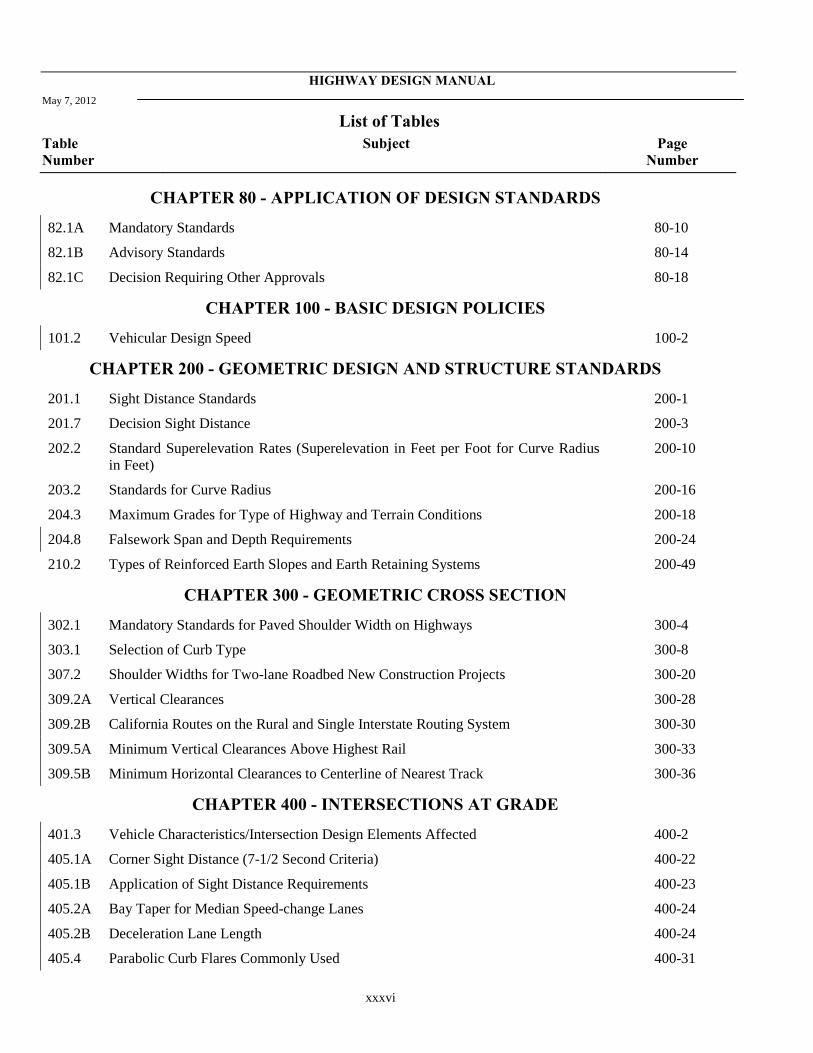
CHAPTER 80 - APPLICATION OF DESIGN STANDARDS
82.1A Mandatory Standards 80-10
82.1B Advisory Standards 80-14
82.1C Decision Requiring Other Approvals 80-18
CHAPTER 100 - BASIC DESIGN POLICIES
101.2 Vehicular Design Speed 100-2
CHAPTER 200 - GEOMETRIC DESIGN AND STRUCTURE STANDARDS
201.1 Sight Distance Standards 200-1
201.7 Decision Sight Distance 200-3
202.2 Standard Superelevation Rates (Superelevation in Feet per Foot for Curve Radius in Feet)
200-10
203.2 Standards for Curve Radius 200-16
204.3 Maximum Grades for Type of Highway and Terrain Conditions 200-18
204.8 Falsework Span and Depth Requirements 200-24
210.2 Types of Reinforced Earth Slopes and Earth Retaining Systems 200-49
CHAPTER 300 - GEOMETRIC CROSS SECTION
302.1 Mandatory Standards for Paved Shoulder Width on Highways 300-4
303.1 Selection of Curb Type 300-8
307.2 Shoulder Widths for Two-lane Roadbed New Construction Projects 300-20
309.2A Vertical Clearances 300-28
309.2B California Routes on the Rural and Single Interstate Routing System 300-30
309.5A Minimum Vertical Clearances Above Highest Rail 300-33
309.5B Minimum Horizontal Clearances to Centerline of Nearest Track 300-36
CHAPTER 400 - INTERSECTIONS AT GRADE
401.3 Vehicle Characteristics/Intersection Design Elements Affected 400-2
405.1A Corner Sight Distance (7-1/2 Second Criteria) 400-22
405.1B Application of Sight Distance Requirements 400-23
405.2A Bay Taper for Median Speed-change Lanes 400-24
405.2B Deceleration Lane Length 400-24
405.4 Parabolic Curb Flares Commonly Used 400-31
HIGHWAY DESIGN MANUAL
May 7, 2012
List of Tables Table Number
Subject Page Number
xxxvii
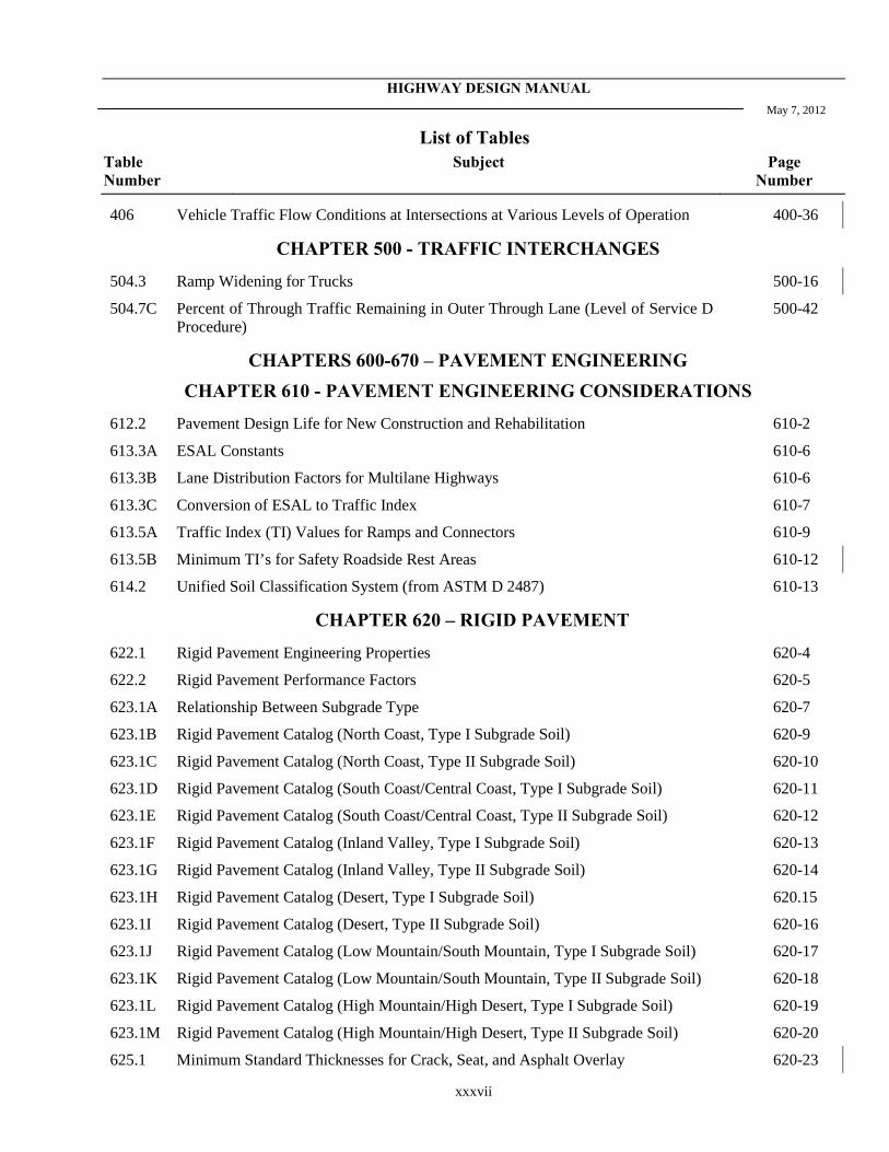
406 Vehicle Traffic Flow Conditions at Intersections at Various Levels of Operation 400-36
CHAPTER 500 - TRAFFIC INTERCHANGES
504.3 Ramp Widening for Trucks 500-16
504.7C Percent of Through Traffic Remaining in Outer Through Lane (Level of Service D Procedure)
500-42
CHAPTERS 600-670 – PAVEMENT ENGINEERING CHAPTER 610 - PAVEMENT ENGINEERING CONSIDERATIONS
612.2 Pavement Design Life for New Construction and Rehabilitation 610-2
613.3A ESAL Constants 610-6
613.3B Lane Distribution Factors for Multilane Highways 610-6
613.3C Conversion of ESAL to Traffic Index 610-7
613.5A Traffic Index (TI) Values for Ramps and Connectors 610-9
613.5B Minimum TI’s for Safety Roadside Rest Areas 610-12
614.2 Unified Soil Classification System (from ASTM D 2487) 610-13
CHAPTER 620 – RIGID PAVEMENT
622.1 Rigid Pavement Engineering Properties 620-4
622.2 Rigid Pavement Performance Factors 620-5
623.1A Relationship Between Subgrade Type 620-7
623.1B Rigid Pavement Catalog (North Coast, Type I Subgrade Soil) 620-9
623.1C Rigid Pavement Catalog (North Coast, Type II Subgrade Soil) 620-10
623.1D Rigid Pavement Catalog (South Coast/Central Coast, Type I Subgrade Soil) 620-11
623.1E Rigid Pavement Catalog (South Coast/Central Coast, Type II Subgrade Soil) 620-12
623.1F Rigid Pavement Catalog (Inland Valley, Type I Subgrade Soil) 620-13
623.1G Rigid Pavement Catalog (Inland Valley, Type II Subgrade Soil) 620-14
623.1H Rigid Pavement Catalog (Desert, Type I Subgrade Soil) 620.15
623.1I Rigid Pavement Catalog (Desert, Type II Subgrade Soil) 620-16
623.1J Rigid Pavement Catalog (Low Mountain/South Mountain, Type I Subgrade Soil) 620-17
623.1K Rigid Pavement Catalog (Low Mountain/South Mountain, Type II Subgrade Soil) 620-18
623.1L Rigid Pavement Catalog (High Mountain/High Desert, Type I Subgrade Soil) 620-19
623.1M Rigid Pavement Catalog (High Mountain/High Desert, Type II Subgrade Soil) 620-20
625.1 Minimum Standard Thicknesses for Crack, Seat, and Asphalt Overlay 620-23
HIGHWAY DESIGN MANUAL May 7, 2012
List of Tables Table Number
Subject Page Number
xxxviii
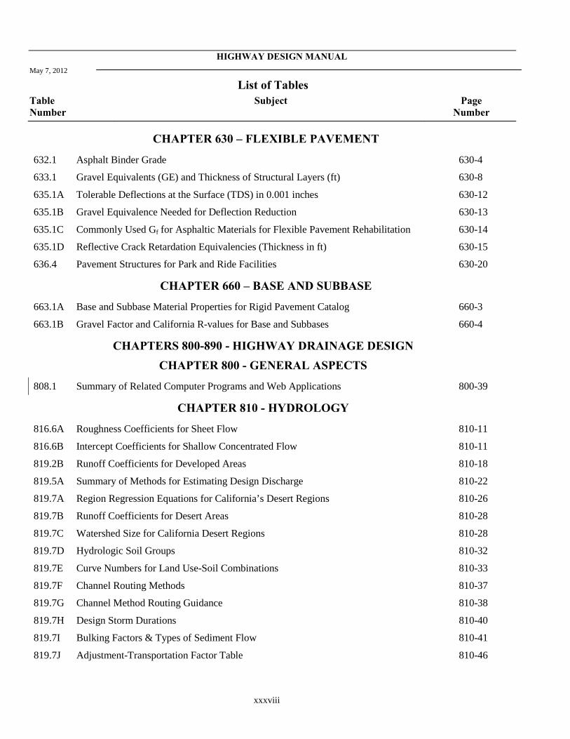
CHAPTER 630 – FLEXIBLE PAVEMENT
632.1 Asphalt Binder Grade 630-4
633.1 Gravel Equivalents (GE) and Thickness of Structural Layers (ft) 630-8
635.1A Tolerable Deflections at the Surface (TDS) in 0.001 inches 630-12
635.1B Gravel Equivalence Needed for Deflection Reduction 630-13
635.1C Commonly Used Gf for Asphaltic Materials for Flexible Pavement Rehabilitation 630-14
635.1D Reflective Crack Retardation Equivalencies (Thickness in ft) 630-15
636.4 Pavement Structures for Park and Ride Facilities 630-20
CHAPTER 660 – BASE AND SUBBASE
663.1A Base and Subbase Material Properties for Rigid Pavement Catalog 660-3
663.1B Gravel Factor and California R-values for Base and Subbases 660-4
CHAPTERS 800-890 - HIGHWAY DRAINAGE DESIGN CHAPTER 800 - GENERAL ASPECTS
808.1 Summary of Related Computer Programs and Web Applications 800-39
CHAPTER 810 - HYDROLOGY
816.6A Roughness Coefficients for Sheet Flow 810-11
816.6B Intercept Coefficients for Shallow Concentrated Flow 810-11
819.2B Runoff Coefficients for Developed Areas 810-18
819.5A Summary of Methods for Estimating Design Discharge 810-22
819.7A Region Regression Equations for California’s Desert Regions 810-26
819.7B Runoff Coefficients for Desert Areas 810-28
819.7C Watershed Size for California Desert Regions 810-28
819.7D Hydrologic Soil Groups 810-32
819.7E Curve Numbers for Land Use-Soil Combinations 810-33
819.7F Channel Routing Methods 810-37
819.7G Channel Method Routing Guidance 810-38
819.7H Design Storm Durations 810-40
819.7I Bulking Factors & Types of Sediment Flow 810-41
819.7J Adjustment-Transportation Factor Table 810-46

HIGHWAY DESIGN MANUAL
May 7, 2012
List of Tables Table Number
Subject Page Number
xxxix
CHAPTER 830 - TRANSPORTATION FACILITY DRAINAGE
831.3 Desirable Roadway Drainage Guidelines 830-3
838.4 Minimum Pipe Diameter for Storm Drain Systems 830-18
CHAPTER 840 - SUBSURFACE DRAINAGE
842.4 Suggested Depth and Spacing of Pipe Underdrains for Various Soil Types 840-5
CHAPTER 850 - PHYSICAL STANDARDS
852.1 Manning "n" Value for Alternative Pipe Materials 850-2
853.1A Allowable Alternative Pipe Liner Materials 850-11
853.1B Guide for Plastic Pipeliner Selection in Abrasive Conditions to Achieve 50 Years of Maintenance-Free Service Life
850-13
854.1 Joint Leakage Selection Criteria 850-18
855.2A Abrasion Levels and Materials 850-22
855.2B Bed Materials Moved by Various Flow Depths and Velocities 850-26
855.2C Guide for Anticipated Service Life Added to Steel Pipe by Abrasive Resistant Protective Coating
850-27
855.2D Guide for Anticipated Wear to Metal Pipe by Abrasive Channel Materials 850-28
855.2E Relative Abrasion Resistance Properties of Pipe an Lining Materials 850-28
855.2F Guide for Minimum Material Thickness of Abrasive Resistant Invert Protection to Achieve 50 Years of Maintenance-Free Service Life
850-29
855.4A Guide for the Protection of Cast-In-Place and Precast Reinforced and Unreinforced Concrete Structures Against Acid and Sulfate Exposure Conditions
850-34
855.4B Guide for Minimum Cover Requirements for Cast-In-Place and Precast Reinforced Concrete Structures for 50-Year Design Life in Chloride Environments
850-35
856.3A Corrugated Steel Pipe Helical Corrugations 850-38
856.3B Corrugated Steel Pipe Helical Corrugations 850-39
856.3C Corrugated Steel Pipe 2⅔" x ½" Annular Corrugations 850-40
856.3D Corrugated Steel Pipe Arches 2⅔" x ½" Helical or Annular Corrugations 850-41
856.3E Steel Spiral Rib Pipe ¾" x 1" Ribs at 11½" Pitch 850-42
856.3F Steel Spiral Rib Pipe ¾" x 1" Ribs at 8½" Pitch 850-43
856.3G Steel Spiral Rib Pipe ¾" x ¾" Ribs at 7½" Pitch 850-44
856.3H Corrugated Aluminum Pipe Annular Corrugations 850-45
856.3I Corrugated Aluminum Pipe Helical Corrugations 850-46

HIGHWAY DESIGN MANUAL May 7, 2012
List of Tables Table Number
Subject Page Number
xl
856.3J Corrugated Aluminum Pipe Arches 2⅔" x ½" Helical or Annular Corrugations 850-47
856.3K Aluminum Spiral Rib Pipe ¾" x 1" Ribs at 11½" Pitch 850-48
856.3L Aluminum Spiral Rib Pipe ¾" x ¾" Ribs at 7½" Pitch 850-49
856.3M Structural Steel Plate Pipe 6" x 2" Corrugations 850-50
856.3N Structural Steel Plate Pipe Arches 6" x 2" Corrugations 850-51
856.3O Structural Aluminum Plate Pipe 9" x 2½" Corrugations 850-52
856.3P Structural Aluminum Plate Pipe Arches 9" x 2½" Corrugations 850-53
856.4 Thermoplastic Pipe Fill Height Tables 850-54
856.5 Minimum Thickness of Cover for Culverts 850-56
857.2 Allowable Alternative Materials 850-58
CHAPTER 860 - OPEN CHANNELS
862.2 Recommended Permissible Velocities for Unlined Channels 860-4
864.3A Average Values for Manning's Roughness Coefficient (n) 860-7
866.2 Guide to Freeboard Height 860-11
CHAPTER 870 - CHANNEL AND SHORE PROTECTION – EROSION CONTROL
872.1 Guide to Selection of Protection 870-5
872.2 Failure Modes and Effects Analysis for Riprap Revetment 870-6
873.3A Guide for Determining RSP-Class of Outside Layer 870-29
873.3B California Layered RSP 870-31
873.3C Minimum Layer Thickness 870-31
873.3D Channel Linings 870-39
873.3E Permissible Velocities for Flexible Channel Linings 870-42
CHAPTER 900 – LANDSCAPE ARCHITECTURE
903.5 Vehicle Parking Stall Standards 900-13
CHAPTER 1000 - BICYCLE TRANSPORTATION DESIGN
1003.1 Bike Path Design Speeds 1000-8
HIGHWAY DESIGN MANUAL 80-1 June 21, 2013
CHAPTER 80 APPLICATION OF DESIGN
STANDARDS Topic 81 - Project Development
Overview Index 81.1 - Philosophy The Project Development process seeks to provide a degree of mobility to users of the transportation system that is in balance with other values. In the development of transportation projects, social, economic, and environmental effects must be considered fully along with technical issues so that final decisions are made in the best overall public interest. Attention should be given to such considerations as:
(a) Need to provide transportation for all users (motorists, bicyclists, transit riders, and pedestrians) of the facility and transportation modes.
(b) Attainment of community goals and objectives.
(c) Needs of low mobility and disadvantaged groups.
(d) Costs and benefits of eliminating or minimizing adverse effects on natural resources, environmental values, public services, aesthetic values, and community and individual integrity .
(e) Planning based on realistic financial estimates.
(f) The cost, ease, and safety of maintaining whatever is built.
Proper consideration of these items requires that a facility be viewed from the perspectives of the user, the nearby community, and larger statewide interests. For the user, efficient travel, mode selection, and safety are paramount concerns. At the same time, the community often is more concerned about local aesthetic, social, and economic impacts. The general population, however, tends to be interested in how successfully a project functions as part of the overall transportation system and how large a share of available capital resources it consumes. Therefore, individual projects must be selected for
construction on the basis of overall system benefits as well as community goals, plans, and values.
Decisions must also emphasize the connectivity between the different transportation modes so that they work together effectively.
The goal is to increase person and goods throughput, highway mobility and safety in a manner that is compatible with, or which enhances, adjacent community values and plans.
81.2 Highway Context The context of a highway is a critical factor when developing the purpose and need statement for a project in addition to making fundamental design decisions such as its typical cross section and when selecting the design elements and aesthetic features such as street furniture and construction materials. Designing a highway that is sensitive to, and respectful of, the surrounding context is critical for project success in the minds of the Department and our stakeholders.
A “one-size-fits-all” design philosophy is not Departmental policy. Designers need to be aware of and sensitive to land use, community context and the associated user needs of the facility. In some instances, the design criteria and standards in this manual are based on the land use contexts in which the State highway is located, for instance: large population areas and downtowns in urban areas, small rural towns and communities, suburban commercial/residential areas, and rural corridors. This approach ensures the standards are flexible, and the approach allows and encourages methods to minimize impacts on scenic, historic, archaeological, environmental, and other important resources.
Beyond their intended transportation benefits, State highways can significantly impact the civic, social and economic conditions of local communities. Designing transportation facilities that integrate the local transportation and land uses while making the design responsive to the other needs of the community support the livability of the community and are usually a complementary goal to meeting the transportation needs of the users of the State highway system.
To do this successfully, the designer needs to have an understanding of the area surrounding the
80-2 HIGHWAY DESIGN MANUAL June 21, 2013 highway and the users of the highway, its function within the regional and State transportation systems, (which includes all transportation modes), and the level of access control needed. To gain this understanding, the designer must consult the Transportation Concept Reports and work with the planning division and the local agencies.
In this manual, the following concepts are used to discuss the context of a highway:
• Place Type - the surrounding built and natural environment;
• Type of Highway - the role the highway plays in terms of providing regional or interregional connectivity and local access; and,
• Access Control - the degree of connection or separation between the highway and the surrounding land use.
A Main Street design is not a solution to creating a specific place type, but a design philosophy to be applied though a community. A main street design serves pedestrians, bicyclists, businesses and public transit with motorized traffic traveling at speeds of 20 to 40 miles per hour. See the Department’s Main Streets Guide for more information.
81.3 Place Types A place type describes the area’s physical environment and the land uses surrounding the State highway. The place types described below are intentionally broad. Place types should be agreed upon in partnership with all of the project stakeholders; however, there likely may be more than one place type within the limits of a project. Ultimately, the place types selected can be used to determine the appropriate application of the guidance provided in this manual. These place type definitions are independent of the Federal government definitions of urban and rural areas. See Title 23 United States Code, Section 13 for further information.
Identifying the appropriate place type(s) involves discussions with the project sponsors, ideally through the Project Development Team (PDT) process, and requires coordination with the land use planning activities associated with the on-going local and regional planning activities. Extensive community engagement throughout both the project planning and project development processes
helps to formulate context sensitive project alternatives and transportation facilities that coordinate with the local land uses.
The following place types are used in this manual:
(1) Rural Areas. Rural areas are typically sparsely settled and developed. They can consist of protected federal and State lands, agricultural lands, and may include tourist and recreational destinations. However, as rural lands transition into rural communities, they can become more developed and suburban and urban-like by providing for a mixture of housing, commercial, industrial and public institutions. For the use of this manual, rural areas have been subcategorized as Natural Corridors, Developing Corridors and City/Town Centers (Rural Main Streets).
(a) Natural Corridors. Typically, the desire in these corridors is to preserve the natural and scenic countryside while at the same time provide transportation services to support the travel and tourism that occurs when visiting these locations. Examples of this place type are: National/State Forests and Parklands; agricultural lands with scattered farm buildings and residences; and, low density development. See Topic 109 for additional information.
(b) Developing Corridors. State highways traveling through these lands tend to be increasingly clustered with industrial, commercial, and residential areas as they lead into a rural city or town center. These corridors can be a transition zone among the aforementioned areas. Highways associated with these locations help to deliver tourists, but they also need to support the local communities and their local economies. In addition, these highways also serve a role and should be efficient at moving people and goods between regions.
Industrial, commercial and retail buildings tend to be located separately from housing and are typically set back from the highway with parking areas placed in front. Truck traffic on these highways tends to serve the needs of these
HIGHWAY DESIGN MANUAL 80-3 June 21, 2013
industrial, commercial and retail buildings; however, there will be a component of the truck traffic that is transporting their loads inter-regionally. Therefore, corridors in areas that are in transition may need to accommodate design vehicles.
(c) City or Town Centers (Rural Main Streets). State highways in this scenario are usually a conventional main street through the rural city or town, or they may be the only main street. The use of the State highway in this environment varies depending upon the individual community, as does the mix of buildings, services, businesses, and public spaces. Transit is often present and should be incorporated into the transportation system as appropriate. Transportation improvement projects on these main street highways can be more complicated and costly than similar projects in more rural settings. A balance usually needs to be maintained between the needs of the through traffic and those of the local main street environment. Thus, analyzing the pedestrian and bicyclist needs early in the development of the project and then following through on the agreements during the design of highway projects in these locations can be especially important. Accommodating the pedestrian and bicyclist needs concurrently in projects leads to greater efficiency in the use of funding.
(2) Suburban Areas. Suburban areas lead into and can completely surround urban areas. A mixture of land uses is typical in suburban areas. This land use mixture can consist of housing, retail businesses and services, and may include regional centers such as shopping malls and other similar regional destinations; which are usually associated with suburban communities (cities and towns) that can be connected with larger urban centers and cities. Assessing the needs of pedestrians, bicyclists, and transit users in concert with the vehicular needs of motorists and truck drivers is necessary during the project planning, development and design of highway projects
in these locations. Accommodating all of these needs concurrently into a project leads to greater efficiency in the use of funding. For the use of this manual, suburban areas have been categorized as either Lower Density/Residential Neighborhoods or Higher Density/Regional Community Centers (Suburban Main Streets).
(a) Lower Density / Residential Neighborh-oods. State highways typically do not cross through this place type. This place type usually feeds users onto the State highway system and is typically under the jurisdiction of a local entity. State highways, if they do interact with this place type, usually just connect at the edges of them where the pedestrians, bicyclists, and motor vehicle operators integrate into the highway system that includes transit facilities.
(b) Higher Density / Regional Community Centers (Suburban Main Streets). As suburban areas grow they tend to merge together into each other’s boundaries. Growth in some locations can create “Megacommunities.” While these megacommunities seem to function as individual cities, they typically have multiple distinct community centers that require highways with the capacity to serve not only each center, but the center-to-center traveler needs. These areas typically require the State highway to serve not only the originally urbanized area, but also the newer suburban areas that have been created where the housing, shopping and employment opportunities are all centered. Anticipating and accommodating growth in this place type can be a challenge. State and local governments, the business community and citizens groups, and metropolitan planning organizations all need to agree on how to meet the community needs, and at times the interregional needs of the highway.
(3) Urban and Urbanized Areas. Urban areas generally are the major population centers in the State. Large numbers of people live in these urbanized areas where growth is
80-4 HIGHWAY DESIGN MANUAL June 21, 2013
expected to continue. Bicycling, transit, and walking are important transportation modes in these areas and as the facilities for pedestrians, transit and bicyclists expand in these areas, the percentage and number of travelers walking, using transit and bicycling is also likely to increase. State agencies and the local governmental entities, the business community and citizens groups, congestion Management Agencies and the local/regional metropolitan planning organization (MPO) need to all agree upon the concept of the transportation facilities being provided so that the community needs can be met.
Urban areas are typically high-density locations such as central business districts, downtown communities, and major activity centers. They have a full range of land uses and are associated with a large diversity of activities. For the use of place types in this manual, urban areas have been categorized as Lower Density Parklands and Residential Neighborhoods and Higher Density Urban Main Streets. Higher Density Urban Main Streets have been further characterized as Community Centers and Downtown Cores.
(a) Lower Density Parklands and Residential Neighborhoods. Large numbers of people live in these urbanized areas and bicycling, transit and walking are important transportation modes in these areas. Parklands can enhance these neighborhoods and parkland preservation is a concern, as well as, access to support travel and tourism to the parklands.
(b) High Density Urban Main Streets.
• Community Centers or Corridor. Strategically improving the design and function of the existing State highways that cross these centers is typically a concern. Providing transportation options to enhancing these urban neighborhoods that combine highway, transit, passenger rail, walking, and biking options are desirable, while they also help promote tourism and shopping.
• Downtown Cores. Similar to community centers, much of the transportation system has already been built and its footprint in the community needs to be preserved while its use may need to be reallocated. Successfully meeting the mobility needs of a major metropolitan downtown core area requires a balanced approach. Such an approach is typically used to enhance the existing transportation network’s performance by adding capacity to the highways, sidewalks, and transit stations for all of the users of the system, and/or adding such enhancement features as HOV lanes, BRT, walkable corridors, etc. Right of way is limited and costly to purchase in these locations. Delivery truck traffic that supports the downtown core businesses can also create problems.
The HEPGIS tool on the FHWA website is available to determine if the project is in an urban area. Urban areas are found on the Highway Information tab of the tool.
81.4 Type of Highway Much of the following terminology is either already discussed in Chapter 20 or defined in Topic 62. The additional information in this portion of the manual is being provided to connect these terms with the guidance that is being provided.
(1) Functional Classification. One of the first steps in the highway design process is to define the function that the facility is to serve. The two major considerations in functionally classifying a highway are access and throughput. Access and mobility are inversely related; as access is increased, mobility decreases. In the AASHTO “A Policy on Geometric Design of Highways and Streets”, highways are functionally classified first as either urban or rural. The hierarchy of the functional highway system within either an urban or rural area consists of the following:

HIGHWAY DESIGN MANUAL 80-5 June 21, 2013
• Principal arterial - main movement (high mobility, limited access) Typically 4 lanes or more;
• Minor arterial - interconnects principal arterials (moderate mobility, limited access) Typically 2 or 3 lanes with turn lanes to benefit through traffic;
• Collectors - connects local roads to arterials (moderate mobility, moderate access) with few businesses; and,
• Local roads and streets - permits access to abutting land (high access, limited mobility).
The California Road System (CRS) maps are the official functional classification maps approved by Federal highway Administration. These maps show functional classification of roads.
(2) Interstate Highways. The interstate highway system was originally designed to be high-speed interregional connectors and it is a portion of the National Highway System (NHS). In urban and suburban areas, a large percentage of vehicular traffic is carried on the interstate highway system, rather than on the local arterials and streets.
(3) State Routes. The State highway system is described in the California Streets and Highway Code, Division 1, Chapter 2 and they are further defined in this manual in Topic 62.3, Highway Types which provides definitions for freeways, expressways, and highways.
81.5 Access Control Index 62.3 defines a controlled access highway and a conventional highway. The level of access control plays a part in determining the design standards that are to be utilized when designing a highway. See Index 405.6 for additional access control guidance.
81.6 Design Standards and Highway Context The design guidance and standards in this manual have been developed with the intent of ensuring that:
• Designers have the ability to design for all modes of travel (vehicular, bicycle, pedestrian, truck and transit); and,
• Designers have the flexibility to tailor a project to the unique circumstances that relate to it and its location, while meeting driver expectation.
Designers should balance the interregional transportation needs with the needs of the communities they pass through. The design of projects should, when possible, expand the options for biking, walking, and transit use. In planning and designing projects, the project development team should work with locals that have any livable policies as revitalizing urban centers, building local economies, and preserving historic sites and scenic country roads. The “Main Streets: Flexibility in Planning, Design and Operations” published by the Department should be consulted for additional guidance as should the FHWA publication “Flexibility in Highway Design”.
Early consultation and discussion with the Design Coordinator and the Design Reviewer during the project initiation document (PID) phase is also necessary to avoid issues that may arise later in the project development process. Design Information Bulletin 78 “Design Checklist for the Development of Geometric Plans” is a tool that can be used to identify and discuss design features that may deviate from standard.
Topic 82 - Application of Standards
82.1 Highway Design Manual Standards (1) General. The highway design criteria and
policies in this manual provide a guide for the engineer to exercise sound judgment in applying standards, consistent with the above Project Development philosophy, in the design of projects. This guidance allows for flexibility in applying design standards and approving design exceptions that take the context of the project location into consideration; which enables the designer to tailor the design, as appropriate, for the specific circumstances while maintaining safety.
80-6 HIGHWAY DESIGN MANUAL June 21, 2013 The design standards used for any project
should equal or exceed the minimum given in the Manual to the maximum extent feasible, taking into account costs (initial and life-cycle), traffic volumes, traffic and safety benefits, right of way, socio-economic and environmental impacts, maintenance, etc. Because design standards have evolved over many years, many existing highways do not conform fully to current standards. It is not intended that current manual standards be applied retroactively to all existing State highways; such is neither warranted nor economically feasible. However, when warranted, upgrading of existing roadway features such as guardrail, lighting, superelevation, roadbed width, etc., should be considered, either as independent projects or as part of larger projects. A record of the decision not to upgrade the existing non-standard mandatory or advisory features shall be provided through the exception process (See Index 82.2).
This manual does not address temporary construction features. It is recognized that the construction conditions encountered are so diverse and variable that it is not practical to set geometric criteria. Guidance for use of traffic control devices for temporary construction zones can be found in Part 6 – Temporary Traffic Control of the California Manual on Uniform Traffic Control Devices (California MUTCD). Guidance for the engineering of pavements in temporary construction zones is available in Index 612.6. In this manual, design standards and guidance are categorized in order of importance in development of a State highway system. See Index 82.4 for other mandatory procedural requirements.
(2) Controlling Criteria. The FHWA has designated thirteen controlling criteria for se-lection of design standards of primary impor-tance for highway safety, listed as follows: design speed, lane width, shoulder width, bridge width, horizontal alignment, vertical alignment, grade, stopping sight distance, cross slope, superelevation, horizontal clear-ance, vertical clearance and bridge structural
capacity. All but the last of these criteria are also designated as geometric criteria.
The design standards related to the 12 geometric criteria are designated as mandatory standards in this manual (see Index 82.1(2) and Table 82.1A).
(3) Mandatory Standards. Mandatory design standards are those considered most essential to achievement of overall design objectives. Many pertain to requirements of law or regulations such as those embodied in the FHWA's 13 controlling criteria (see above). Mandatory standards use the word "shall" and are printed in Boldface type (see Table 82.1A).
(4) Advisory Standards. Advisory design standards are important also, but allow greater flexibility in application to accommodate design constraints or be compatible with local conditions on resurfacing or rehabilitation projects. Advisory standards use the word "should" and are indicated by Underlining (see Table 82.1B).
(5) Decision Requiring Other Approvals. There are design criteria decisions that are not bold or underlined text which require specific approvals from individuals to whom such decisions have been delegated. These individuals include, but are not limited to, District Directors, Traffic Liaisons, Design Coordinators or their combination as specified in this manual. These decisions should be documented as the individual approving desires.
(6) Permissive Standards. All standards other than mandatory, advisory, or decisions requiring other approvals, whether indicated by the use of “should”, “may”, or “can” are permissive.
(7) Other. In addition to the design standards in this manual, see Index 82.7 for general information on the Department’s traffic engineering policy, standards, practices and study warrants.
Caution must be exercised when using other Caltrans publications which provide guidelines for the design of highway facilities,
HIGHWAY DESIGN MANUAL 80-7 June 21, 2013
such as HOV lanes. These publications do not contain design standards; moreover, the designs suggested in these publications do not always meet Highway Design Manual Standards. Therefore, all other Caltrans publications must be used in conjunction with this manual.
82.2 Approvals for Nonstandard Design (1) Mandatory Standards. Design features or
elements which deviate from mandatory standards indicated herein require the approval of the Chief, Division of Design. This approval authority has been delegated to the Design Coordinators, except as noted in Table 82.1A where: (a) the mandatory standard has been delegated to the District Director and (b) the mandatory standards in Chapters 600 through 670 requires the approval of the State Pavement Engineer, and may involve coordination with the Design Coordinator.
The current procedures and documentation requirements pertaining to the approval process for those exceptions to mandatory design standards as well as the dispute resolution process are contained in Chapter 21 of the Project Development Procedures Manual (PDPM).
Design exception approval must be obtained pursuant to the instructions in PDPM Chapter 9.
The Intermodal Surface Transportation Efficiency Act of 1991 (ISTEA) allowed significant delegation to the states by FHWA to approve and administer portions of the Federal-Aid Transportation Program. SAFETEA-LU further allowed delegation to the State DOT’s and in response to this a Joint Stewardship and Oversight Agreement (JSOA) document between FHWA and Caltrans was signed. The JSOA outlines the process to determine specific project related delegation to the Department. The JSOA requires, FHWA approval of exceptions to mandatory design standards related to the 13 controlling criteria on all Interstate projects whether FHWA has oversight responsibilities or not. FHWA approval should be sought as
early in the project development process as possible. However, formal FHWA approval shall not be requested until the appropriate Caltrans representative has approved the design exception.
FHWA approval is not required for exceptions to "Caltrans-only" mandatory standards. Table 82.1A identifies these mandatory stan-dards.
For local facilities crossing the State right of way see Index 308.1.
(2) Advisory Standards. The authority to approve exceptions to advisory standards has been delegated to the District Directors. A list of advisory standards is provided in Table 82.1B. Proposals for exceptions from advisory standards can be discussed with the Design Coordinators during development of the approval documentation. The responsibility for the establishment of procedures for review, documentation, and long term retention of approved exceptions from advisory standards has also been delegated to the District Directors.
(3) Decisions Requiring Other Approvals. The authority to approve specific decisions identified in the text are also listed in Table 82.1C. The form of documentation or other instructions are provided as directed by the approval authority.
82.3 Use of FHWA and AASHTO Standards and Policies The standards in this manual generally conform to the standards and policies set forth in the AASHTO publications, "A Policy on Geometric Design of Highways and Streets" (2001) and "A Policy on Design Standards-Interstate System" (2005). A third AASHTO publication, the latest edition of the "Roadside Design Guide", focuses on creating safer roadsides. These three documents, along with other AASHTO and FHWA publications cited in 23 CFR Ch 1, Part 625, Appendix A, contain most of the current AASHTO policies and standards, and are approved references to be used in conjunction with this manual.
AASHTO policies and standards, which are established as nationwide standards, do not always

80-8 HIGHWAY DESIGN MANUAL June 21, 2013 satisfy California conditions. When standards differ, the instructions in this manual govern, except when necessary for FHWA project approval (Index 108.3, Coordination with the FHWA).
82.4 Mandatory Procedural Requirements Required procedures and policies for which Caltrans is responsible, relating to project clearances, permits, licenses, required tests, documentation, value engineering, etc., are in-dicated by use of the word "must". Procedures and actions to be performed by others (subject to notification by Caltrans), or statements of fact are indicated by the word "will".
82.5 Effective Date for Implementing Revisions to Design Standards Revisions to design standards will be issued with a stated effective date. It is understood that all projects will be designed to current standards unless an exception has been approved in accordance with Index 82.2.
On projects where the project development process has started, the following conditions on the effective date of the new or revised standards will be applied:
• For all projects where the PS&E has not been finalized, the new or revised design standards shall be incorporated unless this would impose a significant delay in the project schedule or a significant increase in the project engineering or construction costs. The Design Coordinator or individual delegated authority must make the final determination on whether to apply the new or previous design standards on a project-by-project basis for roadway features.
• For all projects where the PS&E has been submitted to Headquarters Office Engineer for advertising or the project is under construction, the new or revised standards will be incorporated only if they are identified in the Change Transmittal as requiring special implementation.
For locally-sponsored projects, the Oversight Engineer must inform the funding sponsor within 15 working days of the effective date of any changes in mandatory or advisory design standards as defined in Index 82.2.
82.6 Design Information Bulletins and Other Guidance In addition to the design standards in this manual, Design Information Bulletins (DIBs) establish policies and procedures for the various design specialties of the Department that are in the Division of Design. Some DIBs may eventually become part of this manual, while others are written with the intention to remain as design guidance in the DIB format. References to DIBs are made in this manual by the “base” DIB number only and considered to be the latest version available on the Department Design website. See the Department Design website for further information concerning DIB numbering protocol and postings.
Caution must be exercised when using other Caltrans publications, which provide guidelines for the design of highway facilities, such as HOV lanes. These publications do not contain design standards; moreover, the designs suggested in these publications do not always meet Highway Design Manual Standards. Therefore, all other Caltrans publications must be used in conjunction with this manual.
82.7 Traffic Engineering The Division of Traffic Operations maintains engineering policy, standards, practices and study warrants to direct and guide decision-making on a broad range of design and traffic engineering features and systems, which are provided to meet the site-specific safety and mobility needs of all highway users.
The infrastructure within a highway or freeway corridor, segment, intersection or interchange is not “complete” for drivers, bicyclists and pedestrians unless it includes the appropriate traffic control devices; traffic safety systems; operational features or strategies; and traffic management elements and or systems. The presence or absence of these traffic elements and systems can have a profound effect on safety and operational performance. As such, they are commonly employed to remediate performance deficiencies and to optimize the overall performance of the “built” highway system.

HIGHWAY DESIGN MANUAL 80-9 June 21, 2013 For additional information visit the Division of Traffic Operations website at: http://www.dot.ca.gov/hq/trafficops/
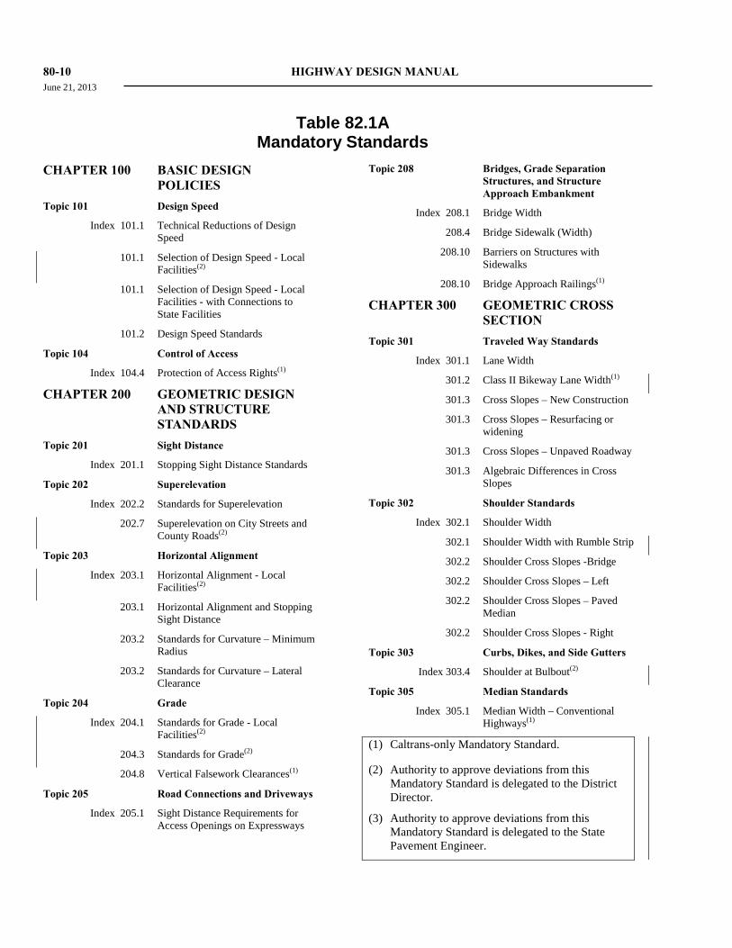
80-10 HIGHWAY DESIGN MANUAL June 21, 2013
Table 82.1A
Mandatory Standards CHAPTER 100 BASIC DESIGN
POLICIES Topic 101 Design Speed
Index 101.1 Technical Reductions of Design Speed
101.1 Selection of Design Speed - Local Facilities(2)
101.1 Selection of Design Speed - Local Facilities - with Connections to State Facilities
101.2 Design Speed Standards
Topic 104 Control of Access Index 104.4 Protection of Access Rights(1)
CHAPTER 200 GEOMETRIC DESIGN AND STRUCTURE STANDARDS
Topic 201 Sight Distance Index 201.1 Stopping Sight Distance Standards
Topic 202 Superelevation Index 202.2 Standards for Superelevation
202.7 Superelevation on City Streets and County Roads(2)
Topic 203 Horizontal Alignment Index 203.1 Horizontal Alignment - Local
Facilities(2) 203.1 Horizontal Alignment and Stopping
Sight Distance 203.2 Standards for Curvature – Minimum
Radius 203.2 Standards for Curvature – Lateral
Clearance
Topic 204 Grade Index 204.1 Standards for Grade - Local
Facilities(2) 204.3 Standards for Grade(2)
204.8 Vertical Falsework Clearances(1)
Topic 205 Road Connections and Driveways Index 205.1 Sight Distance Requirements for
Access Openings on Expressways
Topic 208 Bridges, Grade Separation Structures, and Structure Approach Embankment
Index 208.1 Bridge Width 208.4 Bridge Sidewalk (Width)
208.10 Barriers on Structures with Sidewalks
208.10 Bridge Approach Railings(1)
CHAPTER 300 GEOMETRIC CROSS SECTION
Topic 301 Traveled Way Standards Index 301.1 Lane Width
301.2 Class II Bikeway Lane Width(1)
301.3 Cross Slopes – New Construction
301.3 Cross Slopes – Resurfacing or widening
301.3 Cross Slopes – Unpaved Roadway
301.3 Algebraic Differences in Cross Slopes
Topic 302 Shoulder Standards Index 302.1 Shoulder Width
302.1 Shoulder Width with Rumble Strip
302.2 Shoulder Cross Slopes -Bridge
302.2 Shoulder Cross Slopes – Left
302.2 Shoulder Cross Slopes – Paved Median
302.2 Shoulder Cross Slopes - Right
Topic 303 Curbs, Dikes, and Side Gutters
Index 303.4 Shoulder at Bulbout(2)
Topic 305 Median Standards Index 305.1 Median Width – Conventional
Highways(1)
(1) Caltrans-only Mandatory Standard.
(2) Authority to approve deviations from this Mandatory Standard is delegated to the District Director.
(3) Authority to approve deviations from this Mandatory Standard is delegated to the State Pavement Engineer.

HIGHWAY DESIGN MANUAL 80-11 June 21, 2013
Table 82.1A
Mandatory Standards (Cont.) 305.1 Median Width – Freeways and
Expressways(1)
Topic 307 Cross Sections for State Highways Index 307.2 Shoulder Standards for Two-lane
Cross Sections for New Construction
Topic 308 Cross Sections for Roads Under Other Jurisdictions
Index 308.1 Cross Section Standards for City Streets and County Roads without Connection to State Facilities(2)
308.1 Minimum Width of 2-lane Over-crossing Structures for City Streets and County Roads without Connection to State Facilities(2)
308.1 Cross Section Standards for City Streets and County Roads with Connection to State Facilities(1), (2)
308.1 Two-Lane Local Road Lane Width for City Streets and County Roads within Interchange(2)
308.1 Multi-Lane Local Road Lane Width for City Streets and County Roads within Interchange(2)
308.1 Shoulder Width Standards for City Streets and County Roads Lateral Obstructions(2)
308.1 Shoulder Width Standards for City Streets and County Roads with Curbs and Gutter(2)
308.1 Minimum Width for 2-lane Overcrossing at Interchanges(2)
Topic 309 Clearances Index 309.1 Horizontal Clearances and Stopping
Sight Distance 309.1 Horizontal Clearances
309.2 Vertical Clearances - Major Structures
309.2 Vertical Clearances - Minor Structures
309.2 Vertical Clearances - Rural and Single Interstate Routing System
309.3 Horizontal Tunnel Clearances
309.3 Vertical Tunnel Clearances
309.4 Lateral Clearance for Elevated Structures(1)
309.5 Structures Across or Adjacent to Railroads - Vertical Clearance
Topic 310 Frontage Roads Index 310.1 Frontage Road Width Cross
Section(1), (2)
CHAPTER 400 INTERSECTIONS AT GRADE
Topic 404 Design Vehicles
Index 404.2 Design Vehicle–Traveled Way(1)
404.4 California Legal Design Vehicles on the National Network and on Terminal Access Routes(1)
Topic 405 Intersection Design Standards Index 405.1 Corner Sight Distance – Driver Set
Back 405.1 Corner Sight Distance at Public
Road Intersections 405.1 Corner Sight Distance at Private
Road Intersections 405.2 Left-turn Channelization - Lane
Width
405.2 Left-turn Channelization - Lane Width – Restricted Urban
405.2 Two-way Left-turn Lane Width
405.3 Right-turn Channelization – Lane and Shoulder Width
CHAPTER 500 TRAFFIC INTERCHANGES
Topic 501 General Index 501.3 Interchange Spacing(1)
Topic 502 Interchange Types
Index 502.2 Isolated Off-Ramps and Partial Interchanges(1)
502.3 Route Continuity(1)
(1) Caltrans-only Mandatory Standard.
(2) Authority to approve deviations from this Mandatory Standard is delegated to the District Director.
(3) Authority to approve deviations from this Mandatory Standard is delegated to the State Pavement Engineer.

80-12 HIGHWAY DESIGN MANUAL June 21, 2013
Table 82.1A
Mandatory Standards (Cont.) Topic 504 Interchange Design Standards
Index 504.2 Location of Freeway Entrances & Exits(1)
504.2 Ramp Deceleration Lane and “DL” Distance(1)
504.3 Ramp Lane Width
504.3 Ramp Shoulder Width
504.3 Ramp Lane Drop Taper Past the Limit Line(1)
504.3 Metered Multi-Lane Ramp Lane Drop Taper Past the Limit Line(1)
504.3 Ramp Meters on Connector Ramps(1)
504.3 Lane Drop Transitions on Connector Ramps(1)
504.3 Distance Between Ramp Intersection and Local Road Intersection(1)
504.4 Freeway-to-freeway Connections - Shoulder Width – 1 and 2-Lane
504.4 Freeway-to-freeway Connections - Shoulder Width – 3-Lane
504.7 Minimum Weave Length(1)
504.8 Access Control along Ramps(1)
504.8 Access Control at Ramp Terminal(1)
504.8 Access Rights Opposite Ramp Terminals(1)
CHAPTER 610 PAVEMENT ENGINEERING CONSIDERATIONS
Topic 612 Pavement Design Life
Index 612.2 Design Life for New Construction and Reconstruction(1), (3)
612.3 Pavement Design Life for Widening Projects(1), (3)
612.5 Pavement Design Life for Pavement Roadway Rehabilitation Projects(1),
(3)
Topic 613 Traffic Considerations
Index 613.5 Shoulder Traffic Loading Considerations(1), (3)
CHAPTER 620 RIGID PAVEMENT Topic 622 Engineering Requirements
Index 622.4 Dowel Bars and Tie Bars for New or Reconstructed Rigid Pavements(1), (3)
Index 622.8 Transitions and Terminal Anchors for CRCP(1), (3)
Topic 625 Engineering Procedures for Pavement and Roadway Rehabilitation
Index 625.1 Limits of Paving on Resurfacing Projects(1), (3)
Topic 626 Other Considerations
Index 626.2 Tied Rigid Shoulder Standards(1), (3)
626.2 Tied Rigid Shoulders or Widened Slab Standards(1), (3)
626.2 Tied Rigid Shoulders or Widened Slab at Ramps and Gore Standard(1), (3)
CHAPTER 630 FLEXIBLE PAVEMENT Topic 633 Engineering Procedures for New
& Reconstruction Projects
Index 633.1 Enhancements for Pavement Design Life Greater Than 20 Years(1), (3)
Topic 635 Engineering Procedures for Flexible Pavement and Roadway Rehabilitation
Index 635.1 Limits of Paving on Resurfacing Projects(1), (3)
CHAPTER 640 COMPOSITE PAVEMENTS
Topic 645 Engineering Procedures for Pavement and Roadway Rehabilitation
Index 645.1 Limits of Paving on Overlay Projects(1), (3)
(1) Caltrans-only Mandatory Standard.
(2) Authority to approve deviations from this Mandatory Standard is delegated to the District Director.
(3) Authority to approve deviations from this Mandatory Standard is delegated to the State Pavement Engineer.

HIGHWAY DESIGN MANUAL 80-13 June 21, 2013
Table 82.1A
Mandatory Standards (Cont.) CHAPTER 700 MISCELLANEOUS
STANDARDS Topic 701 Fences
Index 701.2 Fences on Freeways and Expressways(1)
CHAPTER 900 LANDSCAPE ARCHITECTURE
Topic 902 Planting Guidelines
Index 902.3 Trees In Conventional Highway Medians, Distance From Longitudinal End of Median(1)
902.3 The Planting of Trees in Conventional Highway Medians, Less Than 35 mph Posted Speeds(1)
902.3 The Planting of Trees in Conventional Highway Medians, 45 mph or Less Posted Speeds(1)
902.3 The Planting of Trees in Conventional Highway Medians, Greater Than 45 mph Posted Speeds(1)
Topic 903 Safety Roadside Rest Area Design Standards and Guidelines
Index 903.5 Rest Area Ramp Design Topic 904 Vista Point Standards and
Guidelines Index 904.3 Vista Point Ramp Design
CHAPTER 1000 BICYCLE TRANSPORTATION DESIGN
Topic 1003 Design Criteria
Index 1003.1 Class I Bikeway Widths(1), (2) 1003.1 Class I Bikeway Shoulder Width(1),
(2)
1003.1 Class I Bikeway Horizontal Clearance(1), (2)
1003.1 Class I Bikeway Structure Width(1),
(2) 1003.1 Class I Bikeway Vertical
Clearance(1), (2) 1003.1 Class I Bikeway Minimum
Separation From Edge of Traveled Way(1), (2)
1003.1 Physical Barriers Adjacent to Class I Bikeways(1), (2)
1003.1 Class I Bikeway in Medians(1), (2)
1003.1 Class I Bikeway Design Speeds(1), (2) 1003.1 Stopping Sight Distance(2) 1003.1 Obstacle Posts or Bollards in
Bicycle Paths(2)
CHAPTER 1100 HIGHWAY TRAFFIC NOISE ABATEMENT
Topic 1102 Design Criteria Index 1102.2 Horizontal Clearance to Noise
Barrier 1102.2 Noise Barrier on Safety Shape
Concrete Barrier(1)
(1) Caltrans-only Mandatory Standard.
(2) Authority to approve deviations from this Mandatory Standard is delegated to the District Director.
(3) Authority to approve deviations from this Mandatory Standard is delegated to the State Pavement Engineer.
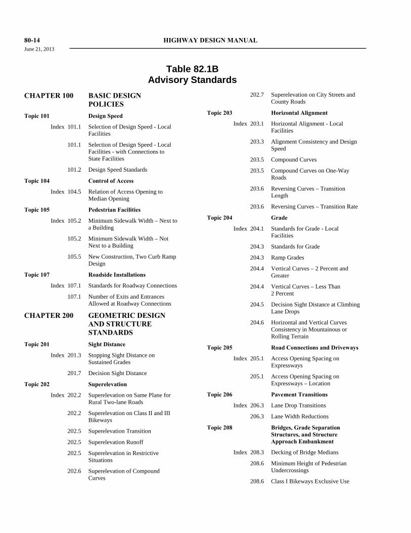
80-14 HIGHWAY DESIGN MANUAL June 21, 2013
Table 82.1B
Advisory Standards CHAPTER 100 BASIC DESIGN
POLICIES Topic 101 Design Speed
Index 101.1 Selection of Design Speed - Local Facilities
101.1 Selection of Design Speed - Local Facilities - with Connections to State Facilities
101.2 Design Speed Standards
Topic 104 Control of Access Index 104.5 Relation of Access Opening to
Median Opening Topic 105 Pedestrian Facilities
Index 105.2 Minimum Sidewalk Width – Next to a Building
105.2 Minimum Sidewalk Width – Not Next to a Building
105.5 New Construction, Two Curb Ramp Design
Topic 107 Roadside Installations Index 107.1 Standards for Roadway Connections
107.1 Number of Exits and Entrances Allowed at Roadway Connections
CHAPTER 200 GEOMETRIC DESIGN AND STRUCTURE STANDARDS
Topic 201 Sight Distance Index 201.3 Stopping Sight Distance on
Sustained Grades 201.7 Decision Sight Distance
Topic 202 Superelevation Index 202.2 Superelevation on Same Plane for
Rural Two-lane Roads 202.2 Superelevation on Class II and III
Bikeways
202.5 Superelevation Transition
202.5 Superelevation Runoff
202.5 Superelevation in Restrictive Situations
202.6 Superelevation of Compound Curves
202.7 Superelevation on City Streets and County Roads
Topic 203 Horizontal Alignment Index 203.1 Horizontal Alignment - Local
Facilities 203.3 Alignment Consistency and Design
Speed
203.5 Compound Curves
203.5 Compound Curves on One-Way Roads
203.6 Reversing Curves – Transition Length
203.6 Reversing Curves – Transition Rate
Topic 204 Grade Index 204.1 Standards for Grade - Local
Facilities 204.3 Standards for Grade 204.3 Ramp Grades
204.4 Vertical Curves – 2 Percent and Greater
204.4 Vertical Curves – Less Than 2 Percent
204.5 Decision Sight Distance at Climbing Lane Drops
204.6 Horizontal and Vertical Curves Consistency in Mountainous or Rolling Terrain
Topic 205 Road Connections and Driveways Index 205.1 Access Opening Spacing on
Expressways 205.1 Access Opening Spacing on
Expressways – Location
Topic 206 Pavement Transitions Index 206.3 Lane Drop Transitions
206.3 Lane Width Reductions Topic 208 Bridges, Grade Separation
Structures, and Structure Approach Embankment
Index 208.3 Decking of Bridge Medians 208.6 Minimum Height of Pedestrian
Undercrossings
208.6 Class I Bikeways Exclusive Use
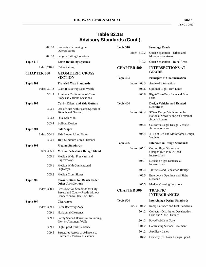
HIGHWAY DESIGN MANUAL 80-15 June 21, 2013
Table 82.1B
Advisory Standards (Cont.) 208.10 Protective Screening on
Overcrossings
208.10 Bicycle Railing Locations
Topic 210 Earth Retaining Systems Index 210.6 Cable Railing
CHAPTER 300 GEOMETRIC CROSS SECTION
Topic 301 Traveled Way Standards Index 301.2 Class II Bikeway Lane Width
301.3 Algebraic Differences of Cross Slopes at Various Locations
Topic 303 Curbs, Dikes, and Side Gutters 303.1 Use of Curb with Posted Speeds of
40 mph and Greater 303.3 Dike Selection
303.4 Bulbout Design
Topic 304 Side Slopes Index 304.1 Side Slopes 4:1 or Flatter
304.1 18 ft Minimum Catch Distance Topic 305 Median Standards
Index 305.1 Median Pedestrian Refuge Island
305.1 Median Width Freeways and Expressways
305.1 Median With Conventional Highways
305.2 Median Cross Slopes
Topic 308 Cross Sections for Roads Under Other Jurisdictions
Index 308.1 Cross Section Standards for City Streets and County Roads without Connection to State Facilities
Topic 309 Clearances Index 309.1 Clear Recovery Zone
309.1 Horizontal Clearance
309.1 Safety Shaped Barriers at Retaining, Pier, or Abutment Walls
309.1 High Speed Rail Clearance
309.5 Structures Across or Adjacent to Railroads - Vertical Clearance
Topic 310 Frontage Roads Index 310.2 Outer Separation – Urban and
Mountainous Areas 310.2 Outer Separation – Rural Areas
CHAPTER 400 INTERSECTIONS AT GRADE
Topic 403 Principles of Channelization Index 403.3 Angle of Intersection
403.6 Optional Right-Turn Lanes
403.6 Right-Turn-Only Lane and Bike Lane
Topic 404 Design Vehicles and Related Definitions
Index 404.4 STAA Design Vehicles on the National Network and on Terminal Access Routes
404.4 California Legal Design Vehicle Accommodation
404.4 45-Foot Bus and Motorhome Design Vehicle
Topic 405 Intersection Design Standards Index 405.1 Corner Sight Distance at
Unsignalized Public Road Intersections
405.1 Decision Sight Distance at Intersections
405.4 Traffic Island Pedestrian Refuge
405.5 Emergency Openings and Sight Distance
405.5 Median Opening Locations
CHAPTER 500 TRAFFIC INTERCHANGES
Topic 504 Interchange Design Standards Index 504.2 Ramp Entrance and Exit Standards
504.2 Collector-Distributor Deceleration Lane and “DL” Distance
504.2 Paved Width at Gore
504.2 Contrasting Surface Treatment 504.2 Auxiliary Lanes
504.2 Freeway Exit Nose Design Speed
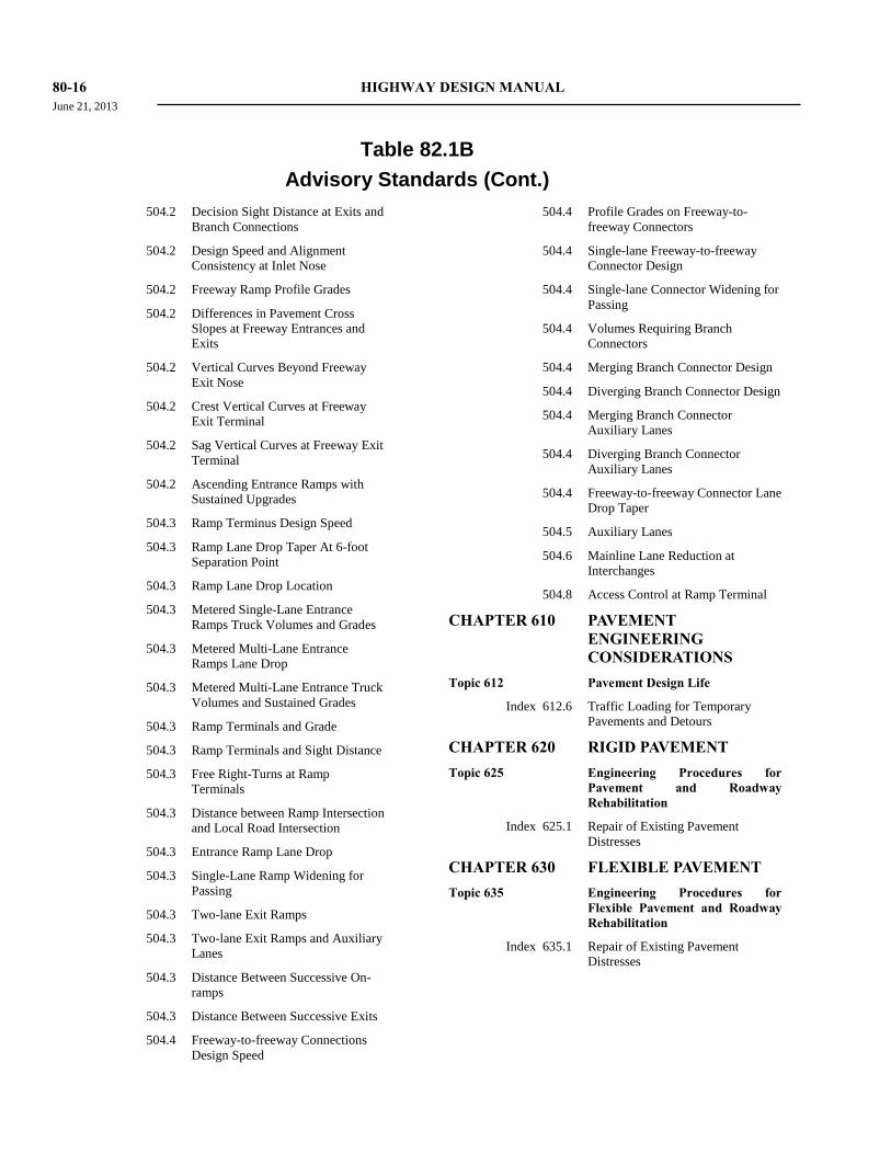
80-16 HIGHWAY DESIGN MANUAL June 21, 2013
Table 82.1B
Advisory Standards (Cont.) 504.2 Decision Sight Distance at Exits and
Branch Connections
504.2 Design Speed and Alignment Consistency at Inlet Nose
504.2 Freeway Ramp Profile Grades
504.2 Differences in Pavement Cross Slopes at Freeway Entrances and Exits
504.2 Vertical Curves Beyond Freeway Exit Nose
504.2 Crest Vertical Curves at Freeway Exit Terminal
504.2 Sag Vertical Curves at Freeway Exit Terminal
504.2 Ascending Entrance Ramps with Sustained Upgrades
504.3 Ramp Terminus Design Speed
504.3 Ramp Lane Drop Taper At 6-foot Separation Point
504.3 Ramp Lane Drop Location
504.3 Metered Single-Lane Entrance Ramps Truck Volumes and Grades
504.3 Metered Multi-Lane Entrance Ramps Lane Drop
504.3 Metered Multi-Lane Entrance Truck Volumes and Sustained Grades
504.3 Ramp Terminals and Grade
504.3 Ramp Terminals and Sight Distance
504.3 Free Right-Turns at Ramp Terminals
504.3 Distance between Ramp Intersection and Local Road Intersection
504.3 Entrance Ramp Lane Drop
504.3 Single-Lane Ramp Widening for Passing
504.3 Two-lane Exit Ramps
504.3 Two-lane Exit Ramps and Auxiliary Lanes
504.3 Distance Between Successive On-ramps
504.3 Distance Between Successive Exits
504.4 Freeway-to-freeway Connections Design Speed
504.4 Profile Grades on Freeway-to-freeway Connectors
504.4 Single-lane Freeway-to-freeway Connector Design
504.4 Single-lane Connector Widening for Passing
504.4 Volumes Requiring Branch Connectors
504.4 Merging Branch Connector Design
504.4 Diverging Branch Connector Design
504.4 Merging Branch Connector Auxiliary Lanes
504.4 Diverging Branch Connector Auxiliary Lanes
504.4 Freeway-to-freeway Connector Lane Drop Taper
504.5 Auxiliary Lanes
504.6 Mainline Lane Reduction at Interchanges
504.8 Access Control at Ramp Terminal
CHAPTER 610 PAVEMENT ENGINEERING CONSIDERATIONS
Topic 612 Pavement Design Life
Index 612.6 Traffic Loading for Temporary Pavements and Detours
CHAPTER 620 RIGID PAVEMENT Topic 625 Engineering Procedures for
Pavement and Roadway Rehabilitation
Index 625.1 Repair of Existing Pavement Distresses
CHAPTER 630 FLEXIBLE PAVEMENT Topic 635 Engineering Procedures for
Flexible Pavement and Roadway Rehabilitation
Index 635.1 Repair of Existing Pavement Distresses

HIGHWAY DESIGN MANUAL 80-17 June 21, 2013
Table 82.1B
Advisory Standards (Cont.) CHAPTER 640 COMPOSITE
PAVEMENTS Topic 645 Engineering Procedures for
Pavement and Roadway Rehabilitation
Index 645.1 Repair of Existing Pavement Distresses
CHAPTER 700 MISCELLANEOUS STANDARDS
Topic 701 Fences Index 701.2 Fences on Freeways and
Expressways
CHAPTER 900 LANDSCAPE ARCHITECTURE
Topic 902 Planting Guidelines Index 902.1 Planting on Freeway Medians
902.2 Sight Distance to Mature Planting 902.2 Clear Recovery Zone to Mature
Planting
902.2 Minimum Setback of Trees
902.3 The Planting of Trees On Conventional Highway Roadsides, Various Posted Speeds and Conditions
Topic 904 Vista Point Standards and Guidelines
Index 904.3 Road Connections to Vista Points
CHAPTER 1000 BICYCLE TRANSPORTATION DESIGN
Topic 1003 Bikeway Design Criteria Index 1003.1 Class I Bikeway Horizontal
Clearance

80-18 HIGHWAY DESIGN MANUAL June 21, 2013
Table 82.1C
Decision Requiring Other Approvals CHAPTER 100 BASIC DESIGN
POLICIES
Topic 103 Design Designation
Index 103.2 Design Period
Topic 108 Coordination With Other Agencies
Index 108.2 Transit Loading Facilities – Location
108.2 Transit Loading Facilities - ADA
108.3 Rail Crossings*
108.3 Parallel Rail Facilities*
108.5 Bus Rapid Transit – Location and ADA
108.7 Coordination With the FHWA - Approvals
Topic 110 Special Considerations
Index 110.1 Overload Category
110.8 Safety Review Items and Employee Exposure
110.10 Proprietary Items
110.10 Proprietary Items – On Structure
110.10 Proprietary Items – National Highway System
Topic 111 Material Sites and Disposal Sites
Index 111.1 Mandatory Material Sites on Federal-aid Projects
111.6 Mandatory Material Sites and Disposal Sites on Federal-aid Projects
Topic 116 Bicyclists and Pedestrians on Freeway
Index 116 Bicycles and Pedestrians on Freeways
CHAPTER 200 GEOMETRIC DESIGN AND STRUCTURE STANDARDS
Topic 204 Grade
Index 204.8 Grade Line of Structures – Temporary Vertical Clearances
Topic 205 Road Connections and Driveways
Index 205.1 Conversion of a Private Opening
Topic 208.10 Bridge Barriers and Railing
Index 208.10 Barrier Separation and Bridge Rail Selection
208.10 Concrete Barrier Type 80
208.10 Concrete Barrier Type 80SW
208.11 Deviations from Foundation and Embankment Recommendations
210.4 Cost Reduction Incentive Proposals
CHAPTER 300 GEOMETRIC CROSS SECTION
Topic 303 Curbs, Dikes, and Side Gutters
Index 303.4 Busbulbs
Topic 304 Side Slopes
Index 304.1 Side Slopes – Erosion Control
304.1 Side Slopes – Structural Integrity
309.2 Vertical Clearance on National Highway System
309.2 Vertical Clearance Above Railroad Facilities
309.5 Horizontal and Vertical Clearances at Railroad Structures
CHAPTER 500 TRAFFIC INTERCHANGES
Topic 502 Interchange Types
Index 502.2 Single Point Interchange Interchanges
502.2 Other Types of Interchanges
Topic 503 Interchange Procedure
Index 503.2 Interchange Geometrics
Topic 504 Interchange Design Standards
Index 504.3 HOV Preferential Lane
504.3 Modification to Existing HOV Preferential Lanes
504.3 Enforcement Areas and Maintenance Pullouts – Required Enforcement Area
504.3 Enforcement Areas and Maintenance Pullouts – Removal
* Authority to approve deviations from this “Decision Requirement” is delegated to the District Director.
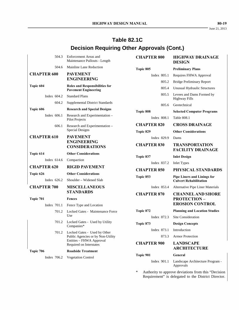
HIGHWAY DESIGN MANUAL 80-19 June 21, 2013
Table 82.1C
Decision Requiring Other Approvals (Cont.) 504.3 Enforcement Areas and
Maintenance Pullouts - Length
504.6 Mainline Lane Reduction
CHAPTER 600 PAVEMENT ENGINEERING
Topic 604 Roles and Responsibilities for Pavement Engineering
Index 604.2 Standard Plans
604.2 Supplemental District Standards
Topic 606 Research and Special Designs
Index 606.1 Research and Experimentation – Pilot Projects
606.1 Research and Experimentation – Special Designs
CHAPTER 610 PAVEMENT ENGINEERING CONSIDERATIONS
Topic 614 Other Considerations
Index 614.6 Compaction
CHAPTER 620 RIGID PAVEMENT Topic 626 Other Considerations
Index 626.2 Shoulder – Widened Slab
CHAPTER 700 MISCELLANEOUS STANDARDS
Topic 701 Fences
Index 701.1 Fence Type and Location
701.2 Locked Gates - Maintenance Force Use
701.2 Locked Gates - Used by Utility Companies*
701.2 Locked Gates - Used by Other Public Agencies or by Non-Utility Entities – FHWA Approval Required on Interstates
Topic 706 Roadside Treatment
Index 706.2 Vegetation Control
CHAPTER 800 HIGHWAY DRAINAGE DESIGN
Topic 805 Preliminary Plans
Index 805.1 Requires FHWA Approval
805.2 Bridge Preliminary Report
805.4 Unusual Hydraulic Structures
805.5 Levees and Dams Formed by Highway Fills
805.6 Geotechnical
Topic 808 Selected Computer Programs
Index 808.1 Table 808.1
CHAPTER 820 CROSS DRAINAGE Topic 829 Other Considerations
Index 829.9 Dams
CHAPTER 830 TRANSPORTATION FACILITY DRAINAGE
Topic 837 Inlet Design
Index 837.2 Inlet Types
CHAPTER 850 PHYSICAL STANDARDS Topic 853 Pipe Liners and Linings for
Culvert Rehabilitation
Index 853.4 Alternative Pipe Liner Materials
CHAPTER 870 CHANNEL AND SHORE PROTECTION – EROSION CONTROL
Topic 872 Planning and Location Studies
Index 872.3 Site Consideration
Topic 873 Design Concepts
Index 873.1 Introduction
873.3 Armor Protection
CHAPTER 900 LANDSCAPE ARCHITECTURE
Topic 901 General
Index 901.1 Landscape Architecture Program - Approvals
* Authority to approve deviations from this “Decision Requirement” is delegated to the District Director.
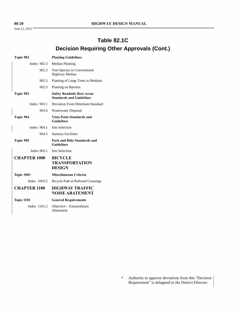
80-20 HIGHWAY DESIGN MANUAL June 21, 2013
Table 82.1C
Decision Requiring Other Approvals (Cont.) Topic 902 Planting Guidelines
Index 902.3 Median Planting
902.3 Tree Species in Conventional Highway Median
902.3 Planting of Large Trees in Medians
902.3 Planting on Barriers
Topic 903 Safety Roadside Rest Areas Standards and Guidelines
Index 903.1 Deviation From Minimum Standard
903.6 Wastewater Disposal
Topic 904 Vista Point Standards and Guidelines
Index 904.1 Site Selection
904.3 Sanitary Facilities
Topic 905 Park and Ride Standards and Guidelines
Index 905.1 Site Selection
CHAPTER 1000 BICYCLE TRANSPORTATION DESIGN
Topic 1003 Miscellaneous Criteria
Index 1003.5 Bicycle Path at Railroad Crossings
CHAPTER 1100 HIGHWAY TRAFFIC NOISE ABATEMENT
Topic 1101 General Requirements
Index 1101.2 Objective – Extraordinary Abatement
* Authority to approve deviations from this “Decision
Requirement” is delegated to the District Director.
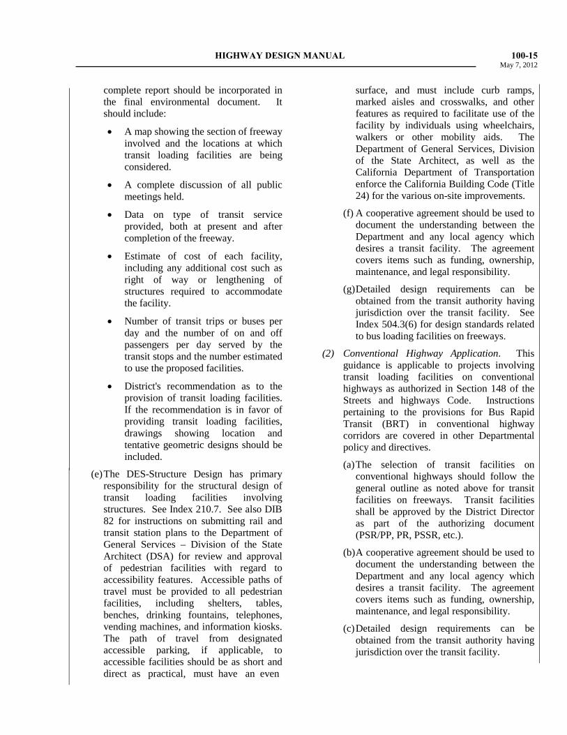
HIGHWAY DESIGN MANUAL 100-15 May 7, 2012 complete report should be incorporated in
the final environmental document. It should include:
• A map showing the section of freeway involved and the locations at which transit loading facilities are being considered.
• A complete discussion of all public meetings held.
• Data on type of transit service provided, both at present and after completion of the freeway.
• Estimate of cost of each facility, including any additional cost such as right of way or lengthening of structures required to accommodate the facility.
• Number of transit trips or buses per day and the number of on and off passengers per day served by the transit stops and the number estimated to use the proposed facilities.
• District's recommendation as to the provision of transit loading facilities. If the recommendation is in favor of providing transit loading facilities, drawings showing location and tentative geometric designs should be included.
(e) The DES-Structure Design has primary responsibility for the structural design of transit loading facilities involving structures. See Index 210.7. See also DIB 82 for instructions on submitting rail and transit station plans to the Department of General Services – Division of the State Architect (DSA) for review and approval of pedestrian facilities with regard to accessibility features. Accessible paths of travel must be provided to all pedestrian facilities, including shelters, tables, benches, drinking fountains, telephones, vending machines, and information kiosks. The path of travel from designated accessible parking, if applicable, to accessible facilities should be as short and direct as practical, must have an even
surface, and must include curb ramps, marked aisles and crosswalks, and other features as required to facilitate use of the facility by individuals using wheelchairs, walkers or other mobility aids. The Department of General Services, Division of the State Architect, as well as the California Department of Transportation enforce the California Building Code (Title 24) for the various on-site improvements.
(f) A cooperative agreement should be used to document the understanding between the Department and any local agency which desires a transit facility. The agreement covers items such as funding, ownership, maintenance, and legal responsibility.
(g) Detailed design requirements can be obtained from the transit authority having jurisdiction over the transit facility. See Index 504.3(6) for design standards related to bus loading facilities on freeways.
(2) Conventional Highway Application. This guidance is applicable to projects involving transit loading facilities on conventional highways as authorized in Section 148 of the Streets and highways Code. Instructions pertaining to the provisions for Bus Rapid Transit (BRT) in conventional highway corridors are covered in other Departmental policy and directives.
(a) The selection of transit facilities on conventional highways should follow the general outline as noted above for transit facilities on freeways. Transit facilities shall be approved by the District Director as part of the authorizing document (PSR/PP, PR, PSSR, etc.).
(b) A cooperative agreement should be used to document the understanding between the Department and any local agency which desires a transit facility. The agreement covers items such as funding, ownership, maintenance, and legal responsibility.
(c) Detailed design requirements can be obtained from the transit authority having jurisdiction over the transit facility.
100-16 HIGHWAY DESIGN MANUAL June 21, 2013
(d) See also DIB 82 for instructions on submitting rail and transit station plans to the Department of General Services – Division of the State Architect (DS) for review and approval of pedestrian facilities with regard to accessibility features. Accessible paths of travel must be provided to all pedestrian facilities, including shelters, tables, benches, drinking fountains, telephones, vending machines, and information kiosks. The path of travel from designated accessible parking for persons with disabilities, if applicable, to accessible facilities should be as short and direct as practical, must have an even surface, and must include curb ramps, marked aisles, and crosswalks, and other features as required to facilitate use of the facility with wheelchairs, walkers and other mobility aides. See Topic 404 for guidance regarding the Design Vehicle, and Index 626.4(3) for structural section guidance for bus pads.
108.3 Commuter and Light Rail Facilities Within State Right of Way (1) General. These facilities may cross or operate
parallel to a highway or other multi modal facility owned and operated by the Department. The following guidance covers all rail facilities, and all transportation facilities owned and operated by the Department. See the Project Development Procedures Manual for additional information and procedures regarding encroachments within State right of way. See Index 309.1(4) for high speed rail guidance.
(2) Rail Crossings. Ideally, rail crossings of transportation facilities should be grade separated. Grade separations must not impact the ability of the Department to operate and maintain its facilities, which includes the ability to expand the existing transportation facilities in the future. All rail crossings are to be approved by the District Director. See the California MUTCD for guidance regarding traffic controls for grade crossings.
(3) Parallel Rail Facilities. Rail facilities may be sited within Department right of way when feasible alternatives do not exist for separate facilities. As necessary, rail facilities may be located within the median. If rail facilities are located in the median, they must not impact the ability of the Department to reasonably operate and maintain its facilities, which includes the ability to expand the existing transportation facilities in the foreseeable future. All parallel rail facilities are to be approved by the District Director.
(4) Design Standards. Transit facilities are to be designed and constructed per the standards contained elsewhere in this manual and exceptions are to be documented as discussed in Chapter 80.
(5) Cooperative Agreements. The design and construction of rail facilities within the Department right of way should be covered in a cooperative agreement. Subsequent maintenance and operations requirements should be addressed in a maintenance agreement or encroachment permit as necessary.
108.4 Bus Loading Facilities (1) General. A bus stop is a marked location for
bus loading and unloading. Bus stops may be midblock, adjacent to, but before an intersection (near side) or adjacent to but after an intersection (far side). The far side location is preferred as pedestrians may cross the intersection behind the bus, allowing the bus to re-enter the travel stream following a break in traffic caused by the signal timing.
(2) Design Standards. Transit facilities are to be designed and constructed per the standards contained elsewhere in this manual and exceptions are to be documented as discussed in Chapter 80.
Bus stops and busbays (see Index 303.4(3) for busbays) should have pavement structures designed in accordance with Index 626.4(3). See the “Guide for Geometric Design of Transit Facilities on Highways and Streets”,

HIGHWAY DESIGN MANUAL 700-1 June 21, 2013
CHAPTER 700 MISCELLANEOUS STANDARDS
Topic 701 - Fences Index 701.1 - Type, Intent and Purpose of Fences (1) Purpose of Fences. Fences constructed by the
Department serve the purposes of either establishing control of access, providing visual demarcation or re-establishing private property lines.
Where the purpose of the fence is access control, installation is intended to establish that access is restricted; such fencing is not intended to serve as a complete physical barrier. The adjacent private property owner will assume responsibility for the construction of any fencing or other facilities necessary to contain their personal property.
(2) Type and Intent of Fences. The type and intent of fences should be as described herein and in the Standard Plans and Standard Specifications.
Fence materials, including gates, installed anywhere within the State right of way are considered Departmental fences and are owned, controlled and maintained by Caltrans forces.
As a right of way consideration, Caltrans may construct fences and gates outside the State right of way. Fences and gates constructed outside the State right of way are considered private fences and are owned, controlled and maintained by the external property owner where Caltrans retains neither rights nor obligations for such fences once constructed.
(a) Fences for freeway and expressway access control are Departmental fences commonly placed immediately inside the State right of way to help enforce observance of the acquired access rights. See Index 701.2 for more detailed guidance.
(b) Median fences are Departmental fences constructed to help prevent indiscriminate crossings of the median by vehicles or pedestrians. These fences are a subset of
freeway and expressway access control fences. See Index 701.2 for more detailed guidance.
(c) Private fences may be constructed adjacent to conventional highways if provided via right of way agreement. Placement is typically parallel to the State right of way and outside Caltrans property. See Index 701.3 for more detailed guidance.
Private fences may also be allowed within Caltrans right of way to restrict access to a private facility crossing or as an aesthetic enhancement of Departmental fence. Neither of these situations is common and should be avoided if possible. See Indexes 701.2(3)(e) and 701.3.
(d) Temporary fences are commonly used during project construction to temporarily control access and/or create a visual screen. Temporary fences are also commonly used during reconstruction of either Departmental or private fences. See Index 701.4 for more detailed guidance.
(e) Environmentally Sensitive Area (ESA) fence is a specialty type of temporary Departmental fence, placed within the limits of a construction project and used to identify the location of sensitive biologic resources while establishing a visible boundary. Orange fabric is used to ensure contractor personnel awareness of the ESA location. See Index 701.5 for more detailed guidance.
(f) Species protection fences are Departmental fences placed within Caltrans right of way and used to prohibit movement of specific threatened or endangered species onto the highway. These fences are unique in composition to the species being addressed. Species protection fences may be placed for either permanent or temporary applications. See Indexes 701.2(3)(b) and 701.5 for more detailed guidance.
(g) Enclosure fences are Departmental fences of various types used to secure the perimeter around equipment storage areas from theft or vandalism, provide a perimeter around maintenance stations or

700-2 HIGHWAY DESIGN MANUAL June 21, 2013 other facilities, or otherwise enclose areas
intended for Caltrans use. See Index 701.5 for more detailed guidance.
(3) Approval. The District Director has the authority and responsibility for approval of fence type and location within the standards stated herein.
701.2 Freeway and Expressway Access Control Fence (1) Placement. Departmental fences shall be
provided on freeways and expressways to control access, except as otherwise provided under paragraph (3)(e) below. Freeway fencing or equivalent access control should extend to the limit of the legal access control on local streets at ramp termini.
(2) Standard Fence Types. The standard types of freeway fence are:
(a) Chain Link Fencing--Type CL-6 fence or equivalent access control should be used along the right of way and in the outer separation in urban or developed areas.
(b) Other Fencing--In rural areas, fences on freeways normally should be either Barbed Wire, (Type BW), or Wire Mesh, (Type WM), on either wood or metal posts. Wood posts may be more aesthetic than metal posts, depending on the surrounding terrain.
(c) Median Fencing--Type CL-4 fence, with the distance from the ground to the bottom tension wire increased to 6 inches, should be used where median fencing is required.
(3) Exceptions to Standard Fence Types.
(a) If walls or fences equal to or better than the standard fence in durability, maintenance requirements, and dimensions exist along the right of way line, the standard fence may be omitted or removed. To avoid a gap in the access control, standard fences should be securely joined to the existing fence or wall at its terminals, if the access control line extends beyond these points.
(b) Fences of special design may be installed where needed for wild animal control.
(c) In special cases, where improvements are scattered, the area is aesthetically sensitive, and a lower fence would be in keeping with the height of adjacent property fence, a Type CL-4 fence may be substituted for Type CL-6 along the right of way in locations where Type CL-6 would otherwise be used.
(d) Fencing may be omitted in remote areas where access control appears unnecessary.
(e) In special cases, nonstandard fencing may be considered at freeway ramp terminals on local streets when the adjacent property either is, or is proposed to be, developed in such a way that the owner feels that standard fencing is aesthetically objectionable. If it is concluded that the objection is valid, a more compatible facility may be substituted, subject to the following controls:
• Preference should be given to retaining the standard fence along the ramp to the end of the curb return or beginning of the taper on the local road. Where this is not reasonable, there may be substituted a fence or wall of equal or better durability and utility that is at least 4 feet high relative to the grade of freeway right of way line. Walls, ornamental iron fences with closely spaced members, or chain link fences are examples of acceptable possibilities.
• Along the local road, beyond the end of the curb return or the beginning of the taper, a facility of somewhat lower standards may be employed, if considered appropriate. The minimum allowable height is 2.5 feet above the grade at the edge of the right of way. In addition to the fence types suitable for use along the ramp, split rail fences, wooden picket fences, and permanent planter boxes are examples of possibilities. The intent is to delineate the access control line and discourage access violations in an effective manner.
HIGHWAY DESIGN MANUAL 700-3 June 21, 2013
• Generally, all costs for the removal of the existing freeway fence and the installation and future maintenance of a nonstandard fence are to be the property owner's responsibility under the terms of the encroachment permit authorizing the substitution. On new construction, the property owner is to assume similar costs and responsibili-ties subject to a credit for the value of a standard fence.
(4) Location of Fences. Normally, fences on freeways should be placed adjacent to, but on the freeway side of the right of way line.
Fences in the outer separation normally should be placed as shown in Figure 307.4 so that the area outside of the fence may be relinquished to the local agency.
When viewed at a flat angle, chain link fencing restricts sight distance. This fact should be considered in the location of such fencing at intersections. To eliminate hand maintenance, right-angle jogs should be avoided.
(5) Locked Gates. Locked gates may be provided in access control fences in special situations. A proposal for a locked gate must address a necessity. Although openings controlled by locked gates do not constitute access openings in the usual sense of access control, they must be shown on the plans. When locked gates are proposed there must be a specific reason for each gate. All gates must be kept locked and secured. Locked gates fall into two categories:
(a) Locked gates to be used exclusively for access by highway maintenance forces do not require FHWA approval and may be approved by the District Director. The integrity and security of this access must always be assured. Maintenance forces must also keep gates locked when not being used for the access of persons or equipment. When locked gates are to be used exclusively by highway maintenance forces, one or more of the following criteria apply:
• A circuitous route would be eliminated.
• The gate access would minimize the exposure of maintenance workers to highway traffic.
• Parking is available outside the gate.
• The gate would allow slow moving equipment to be kept off the highway.
• The site is not accessible to maintenance personal or equipment from the freeway.
(b) Proposals for locked gates to be used by utility companies must be submitted to the District Director for approval. The gate submittal must present all pertinent facts and alternate solutions.
Locked gates to be used by other public agencies or by non-utility entities require FHWA approval if the gate is on an Interstate route.
When proposals for locked gates requiring FHWA approval are included in the plans for new construction, including landscaping projects, FHWA approval of such gates will be included in FHWA approval of the project PS&E. Subsequent installations requiring FHWA approval must be submitted separately to FHWA by the Division of Design after approval by the Chief, Division of Design.
701.3 Private Fences (1) Placement. Caltrans will construct or pay the
cost of fences on private property only as a right of way consideration to mitigate damages. Caltrans’ construction of such fences should be limited to:
(a) The reconstruction or replacement of existing fences.
(b) The construction of fences across property that had been previously enclosed by fences.
These criteria apply to all private as well as public lands.
(2) Private Fences Inside the State Right of Way. Private fences may be constructed within the State right of way via Encroachment Permit to restrict access to facilities (e.g., canals)

700-4 HIGHWAY DESIGN MANUAL June 21, 2013 crossing under or through Department-owned
property. A Maintenance Agreement must be executed to provide for future maintenance of the fence and allow access to the private utility.
701.4 Temporary Fences (1) Placement. Temporary fences are located
where necessary in accordance with construction contractor activities and where the right of way rights have been acquired.
(2) Types of Fences. Temporary fence design should conform to the needs of the situation and the length of time to be used. In most access control or demarcation applications the fence fabric will conform to permanent fence standards, while lesser requirements may apply to posts and post footings to more readily accommodate removal when no longer needed.
Temporary fence used during reconstruction of private fences must be of a type adequate to meet the permanent private fence purposes.
701.5 Other Fences (1) ESA and Species Protection Fences. District
Environmental Unit staff must specify the required placement limits and locations for ESA and species protection fences.
ESA fence material requirements are described in Section 14 of the Standard Specifications.
Species protection fences will be uniquely designed to meet the needs of the target species. District Environmental staff will provide information on the necessary design parameters. In many instances, species protection fence will be able to be directly attached to existing freeway or expressway access control fence and thus preclude the need for separate posts. Where species protection fence is to be constructed along conventional highways, it must be constructed inside the State right of way and should not be attached to any private fence that may exist.
(2) Enclosure Fences. Because these fences are commonly intended to provide security for Caltrans facilities, the facility type and location will often dictate the fence design to be used. Standard chain link (CL-6) fence is most common, but additions (barbed wire extension
arms) or alternative designs may be considered. Typically District Maintenance or Traffic Operations will specify any unique design requirements for enclosure fences as they will assume responsibility after construction.
Topic 702 - Miscellaneous Traffic Items
702.1 References (1) Guardrail and Crash Cushions. See Chapter 7
of the Traffic Manual.
(2) Markers. See Part 3 of the California Manual on Uniform Traffic Control Devices (California MUTCD).
(3) Truck Escape Ramps. See Traffic Bulletin No. 24, (1986) and the NCHRP Report 178.
(4) Mailboxes. See the AASHTO Roadside Design Guide, 3rd Edition, Chapter 11, “Erecting Mailboxes on Streets and Highways”.
Topic 703 - Special Structures and Installation
703.1 Truck Weighing Facilities The Division of Traffic Operations coordinates the design and construction of truck weighing facilities with the California Highway Patrol in Sacramento. Typical plans showing geometric details of these facilities are available from the Headquarters Division of Traffic Operations. Districts should refer truck weighing facility maintenance issues to their District maintenance units.
See Index 107.1 for additional details on roadway connections for truck weighing facilities.
703.2 Rockfall Restraining Nets Rockfall Restraining Nets are protective devices designed to control large rockfall events and prevent rock from reaching the traveled way. The systems consist of rectangular panels of woven wire rope vertically supported by steel posts and designed with frictional brake elements capable of absorbing and dissipating high energies. For additional information on the characteristics and applications for rockfall restraining nets, designers

HIGHWAY DESIGN MANUAL 700-5 June 21, 2013 should contact the Division of Engineering Services - Geotechnical Services (DES-GS).
Topic 704 - Contrast Treatment 704.1 Policy In general, delineation should be composed of the standard patterns discussed in Part 3 of the California MUTCD.
Markings include lines and markings applied to the pavement, raised pavement markers, delineators, object markers, and special pavement treatments.
Contrast treatment is designed primarily to provide a black color contrast with an adjacent white surface. Normally, contrast treatment should be used only in special cases such as the following:
(a) To provide continuity of surface texture for the guidance of drivers through construction areas.
(b) To provide added emphasis on an existing facility where driver behavior has demonstrated that standard signs and markings have proven inadequate.
When contrast treatment is applied, a slurry seal should be used.
See Part 3 of the California MUTCD for additional information on contrast treatment.
Topic 705 - Materials and Color Selection
705.1 Special Treatments and Materials Special materials or treatments, such as painted concrete, or vinyl-clad fences, are sometimes proposed for aesthetic reasons, or to comply with special requirements.
The following guidelines are to be used for the selection of these items:
(a) Concrete should not be painted unless exceptional circumstances exist, due to the continuing and expensive maintenance required. Concrete subject to unintentional staining should be textured during construction to minimize the visibility of stains, if other methods of controlling stain-producing runoff or dripping cannot be accomplished.
(b) Vinyl-clad fences are sometimes specified for aesthetic reasons. The cost of this material is higher than that of galvanized steel. Special consideration should be given to the life-cycle cost and maintainability of vinyl-clad fencing prior to selection for use. The use of black or green vinyl-clad mesh for access control fencing, safety fencing at the top of retaining walls, and pedestrian overcrossing fencing is acceptable.
705.2 Colors for Steel Structures Colors for steel bridges and steel sign structures may be green, gray, or neutral tones of brown, tan, or light blue.
Criteria for selection of colors are:
(a) General continuity along any given route.
(b) Coordination of color schemes with adjacent Districts for interdistrict routes.
(c) Requests from local agencies for improvement of aesthetics in their community.
Color selection for steel bridges should be mutually satisfactory to the Division of Engineering Services and the District. The Division of Engineering Services (DES) will initiate the color selection process by submitting the proposed color to the District Landscape Architect for review. The color for steel sign structures will be selected by the District Landscape Architect.
Topic 706 - Roadside Treatment 706.1 Roadside Management A key concept in roadside management is that roadway and roadside design should consider the full life-cycle cost of transportation improvements including the long-term cost of maintenance. The design alternative with the lowest initial construction cost may not be the best solution if this approach will include high recurring maintenance costs. Designers should strive to select design approaches that do not require extensive recurring long-term activities.
A second key roadside management concept is that roadway and roadside design should contribute to the safety of Department maintenance workers by incorporating techniques that eliminate or reduce worker exposure to traffic. More specifically, these

700-6 HIGHWAY DESIGN MANUAL June 21, 2013 management concepts include the following techniques:
• Eliminate the need for recurrent maintenance activities such as vegetation control, herbicide application, pruning, mowing and graffiti removal;
• Facilitate the automation of recurrent maintenance activities such as herbicide application, mowing and litter collection;
• Locate facilities that require recurrent maintenance activity outside the clear recovery zone, or within protected areas;
• Provide safe maintenance worker access to facilities that require recurrent maintenance activity.
To implement this second roadside management concept, the following conditions must be considered in roadway and roadside design projects:
• Metal beam guardrail, including standard railing, terminal system end treatments, guard railing at structure approach and departures, and at fixed objects should include vegetation control. For more detailed information regarding placement of vegetation control consult with both the District Landscape Architect and District Maintenance. See the Standard Plans for minor concrete vegetation control.
• Thrie beam barrier, including single thrie beam barrier, double thrie beam barrier, at structure approach and at fixed objects should include vegetation control. For more detailed information regarding placement of vegetation control consult with both the District Landscape Architect and District Maintenance. See the Standard Plans for minor concrete vegetation control.
• Unpaved narrow strips often result from the construction of noise barriers or concrete barriers beyond the paved shoulder edge. Unpaved strips 15 feet or less in width, parallel and immediately adjacent to the roadway, should be paved to the barrier or wall. Paving these areas eliminates the need for manual vegetation control, and allows automated
equipment to remove litter and debris. Pavement requirements are consistent with the guidance contained in this manual. Contrasting surface treatment such as markings, delineation, or color may also be provided so drivers can distinguish these areas from those intended for vehicular use.
• Unpaved areas greater than 15 feet in width may include vegetation control techniques such as weed control mats, patterned asphalt or stamped concrete paving, or the planting of low maintenance vegetation such as native grasses. Consult the District Landscape Architect and District Maintenance to select and appropriate vegetation control technique.
• Plants, which at maturity may encroach upon required site distances, should be removed. Consult the District Landscape Architect to identify potential encroaching plant material.
• Noise barriers should be designed with a textured aesthetic treatment or planted with vines to reduce maintenance required to control graffiti. Index 902.3 of this manual and the Project Development Procedures Manual contain information of the planting on noise barriers.
• Unpaved area beyond the gore pavement should be paved as per Index 504.2(2).
• Roadside facilities that require recurring maintenance, such as irrigation controllers, electrical controllers, backflow preventers, and valve boxes, should not be placed on the outside of horizontal curves, near gore areas, near auxiliary lanes, or near ramp termini. The designer should strive to place these facilities outside the clear recovery zone, or within a protected area if placement outside the clear recovery zone is not feasible.
• When placing roadside facilities that require recurring maintenance, the designer should strive to include improvements that facilitate safe maintenance access such as maintenance vehicle pullouts, maintenance access paths, walk gates and vehicle gates. It is preferred that access be provided from outside the right-of-way for all facilities that require maintenance access.
HIGHWAY DESIGN MANUAL 700-7 June 21, 2013 • When placing noise barriers in areas with a
narrow right of way, the designer should consider locating a concrete safety shape barrier 3 feet from the face of the noise barrier to provide protected maintenance access to planting and irrigation facilities.
Formal safety reviews for roadside management issues should be accomplished as discussed in Index 110.8. Consult the District Landscape Architect and District Maintenance unit early during design development to identify and address potential roadside management issues, such as avoiding the redundant placement of roadside facilities, or allow for the consolidation of roadside facilities.
706.2 Vegetation Control Weed control fabric or soil sterilant chemicals may be placed under pavement to prevent weed growth through medians, traffic islands, and other paved areas.
The Division of Maintenance is responsible for the selection of herbicides. Approval is required for any changes from the currently approved Standard Specifications and Standard Special Provisions for pesticides and herbicides.
Since soil sterilants may be transported by water, they should not be used where they may affect environmentally sensitive areas, habitat, native vegetation, landscape plantings, agricultural crops, adjacent residential, commercial or recreation areas, streams, or water bodies.
Before specifying soil sterilants, the District Landscape Architect should be consulted to determine the possibility of future planting.
706.3 Topsoil In areas of new construction, quality existing topsoil should be stockpiled and spread during the final stages of construction. The native brush should be crushed or chipped and mixed with the stockpiled soil to maximize natural or organic matter in the soil. Since topsoil contains beneficial microorganisms and seed, it is best to stockpile it in shallow windrows and planted with temporary erosion control so that oxygen can penetrate the soil.
706.4 Irrigation Crossovers for Highway Construction Projects Irrigation crossovers normally consist of a conduit with a waterline crossover and sprinkler control conduit with pull wire. Irrigation crossovers should be provided under new roadways and ramps when future highway planting is anticipated. The District Landscape Architect should be consulted to determine the need for such crossovers as well as size and location. Attention should also be given to extending existing conduits when widening or modifying roadways and ramps.
The following factors should be considered in sizing and locating crossovers:
(a) A standard irrigation crossover consists of a minimum size of 8-inch diameter nominal (DN) conduit, with a 3-inch DN water supply line and a 2-inch DN sprinkler control conduit with pull wire. Sizes of irrigation crossovers and water supply lines are usually larger when nonpotable water is to be used.
(b) Irrigation crossovers are typically spaced 1,000 feet apart on freeways where future highway planting is anticipated. Undercrossings may be considered alternative crossing opportunities.
(c) Drainage facilities should not be used for waterline crossings.
Standard details and special provisions for the irrigation crossover should be furnished by the District Landscape Architect to the Project Engineer for highway construction projects.
706.5 Water Supply Line (Bridge) and Sprinkler Control Conduit for Bridge Water supply line and sprinkler control conduit with pull wire should be provided in new bridge structures.
The District Landscape Architect should be consulted to determine the need for such water supply lines and sprinkler control conduits such as size and location.
Attention should also be given to modifying, changing existing, or installing new water supply lines and sprinkler control conduits when widening or modifying bridge structures.

700-8 HIGHWAY DESIGN MANUAL June 21, 2013 The following factors should be considered in sizing and locating water supply lines and sprinkler control conduits:
(a) Generally, locate on the side of the bridge, nearest the water source.
(b) Consider the maximum water demand and number of irrigation controller stations anticipated to be used. The water supply line should be a minimum 3-inch DN and the conduit for the sprinkler control conduit should be a minimum 2-inch DN and contain a pull wire.
(c) Ductile iron pipe is required for the water supply line for pipes 4-inch DN or larger because of its superior strength and flexible joints.
706.6 Water Supply for Future Roadside Rest Areas, Vista Points, or Planting Provision for a permanent water supply should be included in the major construction project. In the preparation of a major highway construction project, consideration should be given to using the water source needed for construction as part of a future permanent water supply system. If this appears to be a feasible solution, consider such factors as:
(a) Probability of a future planting, vista point, or roadside rest project.
(b) Economy.
(c) Possible reduction in the flexibility of the highway contractor's operation.
The District Landscape Architect should be consulted.
Topic 707 - Slope Treatment Under Structures
707.1 Policy Structure end slope should be treated to:
(a) Protect slopes from erosion.
(b) Improve aesthetics.
(c) Reduce long term maintenance costs.
Caltrans maintenance, landscape architecture, materials, design, and other affected units will
furnish input to determine slope treatment needed at each site. Local agency input should be obtained for urban undercrossings.
All types of slope treatments require adequate drainage facilities for water from the upper roadway. Inadequate drainage is a major source of slope erosion.
707.2 Guidelines for Slope Treatment (a) Full slope paving shall be installed where it is
anticipated that erosion by pedestrians, wind, storm water, or other causes will occur. High landscape maintenance costs caused by inadequate moisture, sunlight, instability to establish vegetation etc., may also justify the use of full slope paving in lieu of planting. The District Landscape Architect will provide aesthetic input and waterline crossover conduit as well as locations for slope paving.
(b) Landscaped structure end slopes may be justified when adjacent slopes are landscaped and when landscaping is compatible with adjacent development. Conditions must exist where plants would have a strong likelihood of survival.
(c) Bare slopes have minimum initial costs and higher maintenance costs which vary with the site. Bare structure end slopes may be justified at rural sites and other areas where anticipated maintenance activity will be low and there is little likelihood for erosion. Appropriate drainage design is critical when slopes are left bare.
(d) Adequate drainage facilities must be provided to prevent saturation of abutment foundation materials and damage to slope treatment.
(e) Additional protection may be required at stream crossings to provide for flow velocity.
707.3 Procedure Based on consultation with the District Landscape Architect and Structures Bridge Architect and in consideration of economic and aesthetic factors, the District will determine, and set forth with the bridge site plan submittal, the type of slope treatment indicating whether:

HIGHWAY DESIGN MANUAL 700-9 June 21, 2013 (a) The Division of Engineering Services is to
design the slope treatment with the bridge and include the cost in the Structure items; or
(b) The District will design the slope treatment and include the details with the road plans.


