NOTE: Because Hubbell has a policy of continuous product improvement, we reserve the right to change design and specifications without notice.
Printed in USA
®
26-2
JULY 2010 OHIO BRASS – AIKEN, SC, USA
NOTE: Because Hubbell has a policy of continuous product improvement, we reserve the right to change design and specifications without notice.
Warranty - MaterialHubbell Power Systems, Inc. warrants all products sold by it to be merchantable (as such term is defined in the Uniform Commercial Code) and to be free from defects in material and workman-ship. Buyer must notify the Company promptly of any claim under this warranty. The Buyer's exclusive remedy for breach of this warranty shall be the repair or replacement, F.O.B. factory, at the Company's option, of any product defective under the warranty which is returned to the Company within one year from the date of shipment. NO OTHER WARRANTY, WHETHER EXPRESS OR ARISING BY OPERATION OF LAW, COURSE OF DEALING, USAGE OF TRADE OR OTHERWISE IMPLIED, SHALL EXIST IN CONNECTION WITH THE COMPANY'S PRODUCTS OR ANY SALE OR USE THEREOF. The Company shall in no event be liable for any loss of profits or any consequential or special damages incurred by Buyer. The Company's warranty shall run only to the first Buyer of a product from the Company, from the Company's distributor, or from an original equipment manufacturer reselling the Company's product, and is non-assignable and non-transferable and shall be of no force and effect if asserted by any per-son other than such first Buyer. This warranty applies only to the use of the product as intended by Seller and does not cover any misapplication or misuse of said product.
Warranty - ApplicationHubbell Power Systems, Inc. does not warrant the accuracy of and results from product or system performance recommendations resulting from any engineering analysis or study. This applies regardless of whether a charge is made for the recommendation, or if it is provided free of charge.
Responsibility for selection of the proper product or application rests solely with the purchaser. In the event of errors or inaccuracies determined to be caused by Hubbell Power Systems, Inc., its liability will be limited to the re-performance of any such analysis or study.
Design .............................................................. 26-6Rod ................................................................... 26-6End Fittings ....................................................... 26-6Weathersheds .................................................. 26-6Interface ............................................................ 26-6Leakage Distance ............................................. 26-6Washability ....................................................... 26-6Mechanical Ratings .......................................... 26-6Lengths Available ............................................. 26-6Product Updates ............................................... 26-6Packaging ......................................................... 26-6Corona Performance ........................................ 26-7Hi*Lite XL 25k SML Data .................................. 26-8Hi*Lite XL 30k SML Data .................................. 26-9Hi*Lite XL 50k SML Data ................................ 26-10End Fitting Detail ............................................ 26-11Key to the Catalog Numbers ........................... 26-11
Hi*Lite XLSuspension Insulators
26-6
JULY 2010 OHIO BRASS – AIKEN, SC, USA
Hi*Lite® XL InsulatorsHi*Lite XL suspension insulators in this publication em-body the latest features available in polymer insulator design and manufacture.
From the early prototypes in 1971, through full scale introduction in 1976, and through the succeeding years, Hi*Lite insulators have featured conservative design and high-quality manufacture.
Today’s Hi*Lite insulators will add to the over 1,000,000 already in service worldwide.
Design
The structural design of the Hi*Lite XL consists of these basic parts:
Rod - Hi*Lite insulator fiberglass rod is produced from the highest quality materials. Strands are aligned for maximum tensile strength. The rod is more than 50 per-cent glass fibers in cross section.
End Fittings - End fittings are steel or ductile iron. They are crimped directly to the rod by a special process originated by Ohio Brass, and later adopted by many other producers. The crimp develops a high percentage of the rod’s inherent tensile strength. It requires no inter-movement of the parts to achieve high strength, nor does it introduce potting compounds or adhesives.
Weathersheds - Weathersheds are high pressure injec-tion molded by Ohio Brass, from the proprietary com-
pound ESP™. Housings manufactured with ESP silicone alloy rubber exhibit hydrophobicity, high mechanical strength, high corona resistance and low permeability to moisture.
Interface - Hi*Lite insulators use Ohio Brass’ live sili-cone interface. This feature prevents intrusion of mois-ture and contaminating elements. If the exterior seal is damaged, redundant o-ring seals within the live silicone interface prohibit the lengthwise migration of intrusive elements between shed and rod.
Leakage Distance
Hi*Lite XL insulators feature high leakage distance for maximum resistance to contamination and leakage cur-rents. Specific leakage distance (leakage divided by dry arcing distance) is higher than porcelain. Contact Ohio Brass if you have extra-high leakage distance needs.
Washability
Hi*Lite insulators listed in this catalog are suitable for flood washing up to 200 psi. The design incorporates positive, labyrinth seals to ensure long-term security against water entry. Conventional dry-particle, air-pressure cleaning methods may also be employed. A cleaning guideline is available from Ohio Brass.
If your washing requirements exceed flood washing, contact Ohio Brass.
Mechanical Ratings
Hi*Lite XL suspension insulators are rated and tested in accordance with ANSI Standard C29.11. Certified test reports in detail are available.
SML ratings are 25k, 30k and 50k pounds.
RTL ratings are consistent with the ANSI standard. Ac-tual factory routine tests are conducted at loads equal to or greater than the RTL rating.
Markings for XL insulator designs are permanently embossed into the ground end corona shielding rings. Markings include SML and RTL, part number, assem-bly date code, and Ohio Brass identification.
Lengths Available
Hi*Lite suspension insulators are available in lengths appropriate for 69 kV through 765 kV. Longer lengths can be produced for special projects. Length incre-ments are approximately three inches.
Product Updates
Hi*Lite XL insulator end fittings are attached with an improved crimping process using the successful principles of earlier Hi*Lite designs. The corona shield has been refined; a more compact Corona Shielding Ring (CSR) provides both electrical stress relief and a mechanical seal at the housing-to-end fitting interface.
Packaging
Hi*Lite suspension insulators are packaged in appropri-ate quantities in wood crates. As an option, Ohio Brass offers packaging of the insulators in individual sleeves.
A
26-7
JULY 2010OHIO BRASS – AIKEN, SC, USA
Normal Applications: Top Grounded, Bottom Energized
Orientation
TopBottom
TopBottom
Insulator
Suspension25/30 K SML
Suspension50 K SML
The physical and electrical values for the insulators on pages 26-8 through 26-10 are shown without corona protection above 161 kV. Ohio Brass has therefore provided the table below that yields the physical and electrical changes to the insulator when rings are installed for voltages above 161 kV.
Corona PerformanceHi*Lite XL suspension insulators are RIV and corona free through 161 kV, by the use of integral Corona Shield Rings (CSR). Due to the small diameter of the end fittings, corona shielding is necessary at 230 kV and above. The table below details the rings necessary for voltages equal to or exceeding that listed in the column header.
Physical & Electrical Change Table
500 kVRings
-5 (-127.0)
0
-30
0
-65
-65
5.1 (2.29)
345 kVRing
-2 (-50.8)
0
-15
0
-25
-30
3 (1.8)
230 kVRing
-1.2 (-30.48)
0
-10
0
-15
-20
3 (1.8)
Physical & ElectricalCharacteristics
Dry Arc Distance inches (mm)
Leakage Distance inches (mm)
60 Hz Flashover Dry - kV
60 Hz Flashover Wet - kV
Critical Flashover Positive - kV
Critical Flashover Negative - kV
Net Weight pounds (kg)
Part Number 271761 Part Number 271705 Part Number 271751
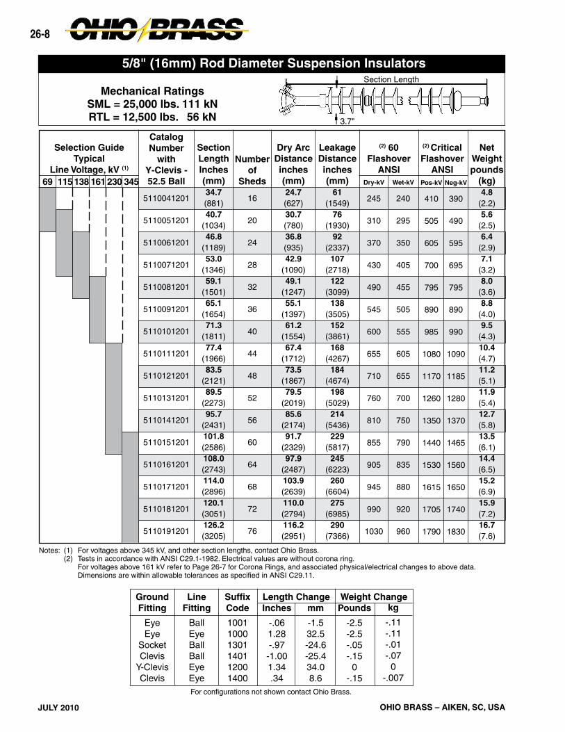
Notes: (1) For voltages above 345 kV, and other section lengths, contact Ohio Brass. (2) Tests in accordance with ANSI C29.1-1982. Electrical values are without corona ring. For voltages above 161 kV refer to Page 26-7 for Corona Rings, and associated physical/electrical changes to above data. Dimensions are within allowable tolerances as specified in ANSI C29.11.
5/8" (16mm) Rod Diameter Suspension InsulatorsSection Length
3.7"
A
26-9
JULY 2010OHIO BRASS – AIKEN, SC, USA
kg
-0.110-0.110-0.010-0.0700.000
-0.007
GroundFitting
EyeEye
SocketClevis
Y-ClevisClevis
LineFitting
BallEyeBallBallEyeEye
SuffixCode
100110001301140112001400
Inches
-0.06 1.28 -0.97 -1.00 1.34 0.34
mm
-1.532.5
-24.6-25.434.08.6
Pounds
-2.50-2.50-0.05-0.150.00
-0.15
Weight ChangeLength Change
For configurations not shown contact Ohio Brass.
Y-Clevis Tower Attachment Detailfor 25k, 30k, and 50k SML Insulators
SML25/30k
50k
“D” Max. Inches.5311.0
To achieve insulator SML value, proper grade steel should be used
Notes: (1) For voltages above 345 kV, and other section lengths, contact Ohio Brass. (2) Tests in accordance with ANSI C29.1-1982. Electrical values are without corona ring. For voltages above 161 kV refer to Page 26-7 for Corona Rings, and associated physical/electrical changes to above data. Dimensions are within allowable tolerances as specified in ANSI C29.11.
Section Length
3.7"
5/8" (16mm) Rod Diameter Suspension Insulators
“D” Max.
3/4" Max.1" Dia. Minimum1/8" x 45° Chamfer
26-10
JULY 2010 OHIO BRASS – AIKEN, SC, USA
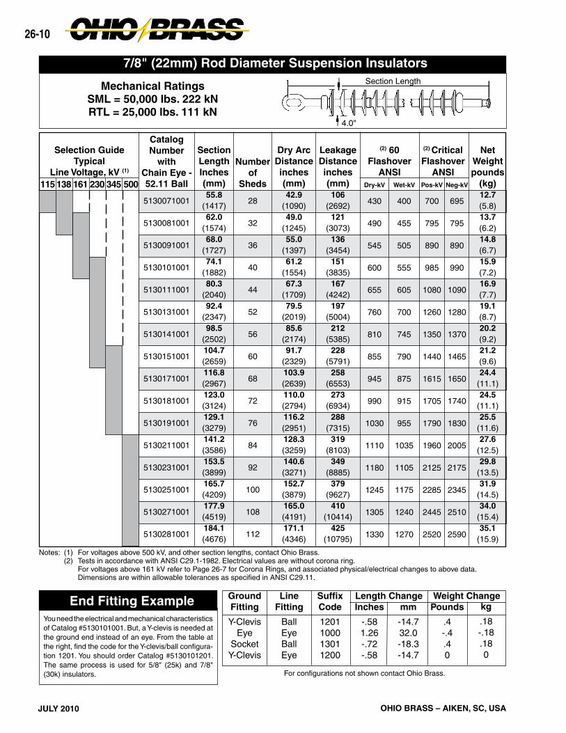
End Fitting ExampleYou need the electrical and mechanical characteristics of Catalog #5130101001. But, a Y-clevis is needed at the ground end instead of an eye. From the table at the right, find the code for the Y-clevis/ball configura-tion 1201. You should order Catalog #5130101201. The same process is used for 5/8" (25k) and 7/8" (30k) insulators.
Notes: (1) For voltages above 500 kV, and other section lengths, contact Ohio Brass. (2) Tests in accordance with ANSI C29.1-1982. Electrical values are without corona ring. For voltages above 161 kV refer to Page 26-7 for Corona Rings, and associated physical/electrical changes to above data. Dimensions are within allowable tolerances as specified in ANSI C29.11.
* For IEC 16mm and 20mm Ball and Socket fittings, contact Ohio Brass.
Weathershed ConfigurationNumber of sheds equals this number times four, plus any added sheds listed in the construction digit.
ANSI Socket*Y-Clevis FittingANSI Ball*Chain Eye
(1) For IEC Ball and Socket fittings, contact Ohio Brass.(2) Metric labeling of ANSI, or IEC insulators.
26-12
JULY 2010 OHIO BRASS – AIKEN, SC, USA
26-13
B
JULY 2010OHIO BRASS – AIKEN, SC, USA
Hi*Lite® XLLine Post Insulators
Table of ContentsPage
Design ............................................................ 26-14Rod ................................................................. 26-14End Fittings ..................................................... 26-14Weathersheds ................................................ 26-14Interface .......................................................... 26-14Leakage Distance ........................................... 26-14Washability ..................................................... 26-14Mechanical Ratings ........................................ 26-14Corona Rings .................................................. 26-15Packaging ....................................................... 26-15Key to 2.5" Catalog Numbers ......................... 26-15Hi*Lite XL 2.5" Rod Horizontal Line Posts ...... 26-16Hi*Lite XL 2.5" Rod Vertical Line Posts .......... 26-17Hi*Lite XL 2.5" Rod Vertical Line Post Assembly .................................................... 26-18Hi*Lite XL 2.5" Rod Base Fittings ................... 26-19Hi*Lite XL 2.5" Rod Line Fittings .................... 26-20Hi*Lite XL 3.0" Rod Horizontal Line Posts ...... 26-21Key to 3.0" Catalog Numbers ......................... 26-21Hi*Lite II 3.0" Rod Horizontal Line Posts ........ 26-22Hi*Lite II 3.0" Rod Vertical Line Posts ............. 26-23Hi*Lite XL 3.0" Rod. Dia. Base Fittings ........... 26-24Hi*Lite XL 3.0" Rod. Dia. Line Fittings ............ 26-25Clamps and Assemblies ................................. 26-26
26-14
JULY 2010 OHIO BRASS – AIKEN, SC, USA
Hi*Lite*® XL InsulatorsHi*Lite XL line post insulators in this publication em-body the latest features available in polymer insulator design and manufacture.
From the early prototypes in 1971, through full scale introduction in 1976, and through the succeeding years, Hi*Lite insulators have featured conservative design and high-quality manufacture.
Today’s Hi*Lite insulators will add to the over 1,000,000 already in service worldwide.
Design
The structural design of the Hi*Lite XL consists of these basic parts:
Rod - Hi*Lite insulator fiberglass rod is produced from the highest quality materials. Strands are aligned for maximum tensile strength. The rod is more than 50 percent glass fibers in cross section.
End Fittings - End fittings are aluminum or ductile iron. They are crimped directly to the rod by a special process originated by Ohio Brass, and later adopted by many other producers. The crimp requires no inter-movement of the parts to achieve high strength, nor does it introduce potting compounds or adhesives.
Weathersheds - Weathersheds are high pressure injection molded by Ohio Brass, from the proprietary compound ESP™. Housings manufactured with ESP silicone alloy rubber exhibit hydrophobicity, high me-chanical strength, high corona resistance and low permeability to moisture.
Interface - Hi*Lite insulators use Ohio Brass’ live sili-cone interface. This feature prevents intrusion of mois-ture and contaminating elements. If the exterior seal is damaged, redundant o-ring seals within the live silicone interface prohibit the lengthwise migration of intrusive elements between shed and rod.
Leakage Distance
Hi*Lite XL insulators feature high leakage distance for maximum resistance to contamination and leakage currents.
Washability
Hi*Lite Line Post insulators listed in this catalog are suitable for flood washing up to 200 psi. The design in-corporates positive, labyrinth seals to ensure long-term security against water entry. Conventional dry-particle, air-pressure cleaning methods may also be employed. A cleaning guideline is available from Ohio Brass.
If your washing requirements exceed flood washing, contact Ohio Brass.
Mechanical Ratings
Line post insulators are basically cantilever support members, with ratings defined as follows:
Specified Cantilever Load (SCL)
SCL is the ultimate cantilever strength rating of the Hi*Lite XL line post insulator. SCL is identical to the minimum average breaking load (ABL) rating in previ-ous catalogs.
Reference Cantilever Load (RCL)
RCL is the maximum recommended load in cantilever that a Hi*Lite XL post insulator is designed to withstand during its life, and is equal to 50% of the SCL. RCL is identical to maximum working load (MWL) listed in pre-vious catalogs. Line design loads applied to post insula-tors often include tension, or compression, in addition to the primary vertical cantilever load. In addition, some longitudinal load is usually designed for as well.
Combined Load
Contact your Hubbell Power Systems representative for combined load applications.
26-15
B
JULY 2010OHIO BRASS – AIKEN, SC, USA
5 2 2 0 1 00 08 1Hi*Lite XLXL Post
Strength2 = 2.5" DIA
Construction0 = Standard1 = Dulled HDW
Weathershed ConfigurationTo determine the number of insulator sheds, multiply this number by two.
Hi*Lite XL Line Post Insulators:Key to the Catalog Numbers
Line End FittingsTwo Hole Blade ...........................0Horizontal Clamptop ...................1Vertical Clamptop .......................25" Bolt Circle (through) ...............5Two Hole Long Blade ..................9
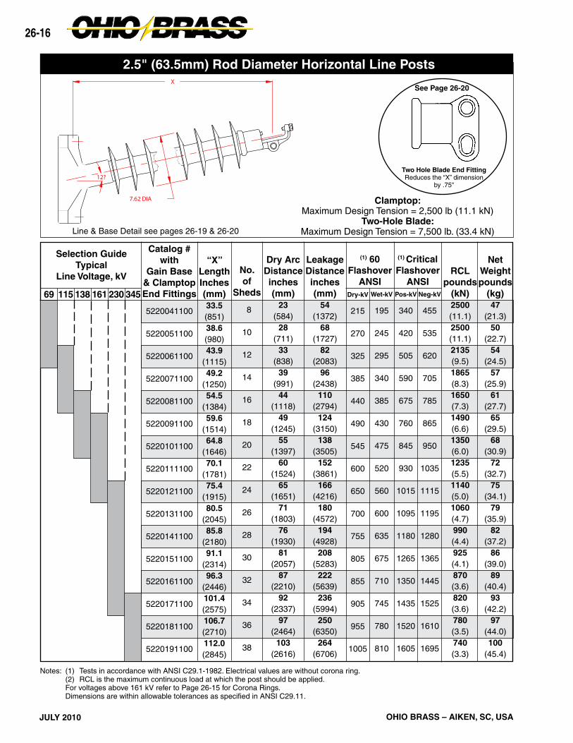
2.5" (63.5mm) Rod Diameter Horizontal Line Posts
Corona RingsHi*Lite XL line post insulators are corona free through 161 kV.
PackagingHi*Lite XL line post insulators are packaged in appro-priate quantities in open wood crates. As an option, Ohio Brass offers packaging of the insulators in indi-vidual sleeves.
Part Number 2721273001Control Ring
Application
Line EndEnergized
Bottom EndEnergized
230 kV
Top - 2721273001Bott - NONE
Top - NONEBott - 2721273001
161 kV & below
Top - NONEBott - NONE
Top - NONEBott - NONE
345 kV
Top - 2721273001Bott - NONE
Top - NONEBott - 2721273001
Base End FittingsUnitary D.I. Gain (15/16" Holes) .......... 00Unitary Flat 8x10 (15/16" Holes) ......... 01Al Gain 12 CL (15/16" Holes) .............. 02Al Flat 8x10 (15/16" Holes) .................. 03Al Flat 8x13 (15/16" Holes) .................. 045" Bolt Circle (tapped 11/16" Holes) .... 05Steel Gain (15/16" Holes) .................... 07Steel Flat 8 x 13 (15/16" Holes) ........... 08
RecommendedTorque10 Ft.-Lb.
RecommendedTorque45 Ft.-Lb.
3.4375
12
(1) Metric labeling only. Insulators and hardware are ANSI.
Labeling1 = English2 = Metric (1)M = English w/12" Corona Ring
26-16
JULY 2010 OHIO BRASS – AIKEN, SC, USA
69 345230138 161115
Selection GuideTypical
Line Voltage, kV
Notes: (1) Tests in accordance with ANSI C29.1-1982. Electrical values are without corona ring. (2) RCL is the maximum continuous load at which the post should be applied. For voltages above 161 kV refer to Page 26-15 for Corona Rings. Dimensions are within allowable tolerances as specified in ANSI C29.11.
Two Hole Blade End FittingReduces the “X” dimension
by .75"
Line & Base Detail see pages 26-19 & 26-20
12?
7.62 DIA
X
26-17
B
JULY 2010OHIO BRASS – AIKEN, SC, USA
Line & Base Fitting Detail see pages 26-19 & 26-20
69
NetWeightpounds
(kg)27
(12.3)30
(13.6)34
(15.4)37
(16.8)41
(18.6)45
(20.4)
Notes: (1) Tests in accordance with ANSI C29.1-1982. (2) RCL is the maximum cantilever continuous load at which the post should be applied. (3) Mounting Base Catalog No. 75115 may be ordered with these Catalog numbers for a vertical assembly.
2.5" (63.5mm) Rod Diameter Vertical Line Post Assembly
Aluminum Alloy6063-T5
Base Detail
To Order an Assembly - Pick an insulator from Table A based on your Electrical and Mechanical needs — next, select a Base configuration from Table B, for your mounting position needs.
0.678 DIA.4 HOLES
5.757.438
1.625
69
(1) Insulators in Table A have the same electrical and mechanical
characteristics as those on Page 26-17 with Code 1205.
Table A
115 138 161
Selection GuideTypical
Line Voltage, kV
(1)Catalog #with VerticalClamptop &Base Code
52200412XX
52200512XX
52200612XX
52200712XX
52200812XX
52200912XX
“A”LengthInches(mm)30.4(772)35.6(904)41.0
(1041)46.4
(1179)51.8
(1316)57.0
(1448)
“XX”Code
20
21
22
23
24
25
26
27
Style
Face
Side
Face
Side
Face
Side
Face
Side
“B”LengthInches(mm)
20(508)
20(508)
20(508)
20(508)31.75(806)31.75(806)31.75(806)31.75(806)
“C”LengthInches(mm)
12(305)
12(305)
12(305)
12(305)
16(406)
16(406)
16(406)
16(406)
“D”Diameter
Inches(mm).8125(21)
.8125(21)
.9375(24)
.9375(24)
.8125(21)
.8125(21)
.9375(24)
.9375(24)
Table B
26-19
B
JULY 2010OHIO BRASS – AIKEN, SC, USA
Al & Steel FlatAl & Steel Gain
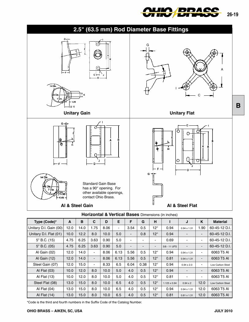
Horizontal & Vertical Bases Dimensions (in inches)
Type (Code)*
Unitary D.I. Gain (00)
Unitary D.I. Flat (01)
5" B.C. (15)
5" B.C. (05)
Al Gain (02)
Al Gain (12)
Steel Gain (07)
Al Flat (03)
Al Flat (13)
Steel Flat (08)
Al Flat (04)
Al Flat (14)
A
12.0
10.0
4.75
4.75
12.0
12.0
12.0
10.0
10.0
13.0
13.0
13.0
B
14.0
12.2
6.25
6.25
14.0
14.0
15.0
12.0
12.0
15.0
15.0
15.0
C
1.75
8.0
3.63
3.63
-
-
-
8.0
8.0
8.0
8.0
8.0
E
-
5.0
5.0
5.0
6.13
6.13
6.5
5.0
5.0
6.5
6.5
6.5
F
3.54
-
-
-
5.56
5.56
6.04
4.0
4.0
4.0
4.0
4.0
D
8.06
10.0
0.90
0.90
8.06
8.06
8.33
10.0
10.0
10.0
10.0
10.0
G
0.5
0.8
-
-
0.5
0.5
0.38
0.5
0.5
0.5
0.5
0.5
H
12°
12°
-
-
12°
12°
12°
12°
12°
12°
12°
12°
I
0.94
0.94
0.69
5/8 - 11 UFS
0.94
0.81
0.94
0.94
0.81
1.125 x 0.94
0.94
0.81
J
0.94 x 1.31
-
-
-
0.94 x 1.31
0.94 x 1.31
0.94 x 2.0
-
-
0.94 x 2
0.94 x 1.31
0.81 x 1.31
K
1.90
-
-
-
-
-
-
-
-
12.0
12.0
12.0
Material
60-45-12 D.I.
60-45-12 D.I.
60-45-12 D.I.
60-45-12 D.I.
6063 T5 Al
6063 T5 Al
Low Carbon Steel
6063 T5 Al
6063 T5 Al
Low Carbon Steel
6063 T5 Al
6063 T5 Al
*Code is the third and fourth numbers in the Suffix Code of the Catalog Number.
Unitary Gain Unitary Flat
2.5" (63.5 mm) Rod Diameter Base Fittings
Standard Gain Base has a 90° opening. For other available openings, contact Ohio Brass.
A
C
G
I
H
26-20
JULY 2010 OHIO BRASS – AIKEN, SC, USA
Two Hole Blade*12° upsweep post angles
Horizontal Clamptop
Vertical ClamptopPart per ANSI C29.7
5" Bolt CircleLine or Base Fitting
Horizontal & Vertical End Fittings Dimensions (in inches)
Material
60-40-18 D.I.
60-40-18 D.I.
60-40-18 D.l.
60-45-12 D.I.
60-45-12 D.I.
60-40-18 D.I.
Type (Code)*
2 Hole Blade (0)
2 Hole Long Blade (9)
H. Clamptop (1)
5" B.C. (3)
5" B.C. (5)
V. Clamptop (2)
L
0.5R
0.5R
-
-
-
-
M
0.44 R
0.44R
-
-
-
-
B
4.0
4.0
4.0
6.25
6.25
4.0
A
5.73
5.73
8.24
4.75
4.75
5.88
C
-
-
3.30
3.63
3.63
3.30
D
0.75
0.75
1.12
0.90
0.90
1.12
E
5.25
7.75
4.72
5.0
5.0
5.37
F
1.25
1.25
4.0
-
-
4.0
G
1.50
4.0
-
-
-
1.06
H
2.00
4.5
-
-
-
-
I
1.0
1.0
5/8 - 11 UFS
5/8 - 11 UFS
0.69 x Holes
5/8 - 11 UFS
J
1.44
1.44
0.75
-
-
-
*Code is the 2nd number in the Suffix Code of the Catalog Number.
Corona RingsHi*Lite XL line post insulators are corona-free through 230 kV line-to-ground.
3.0" (76.2 mm) Rod Diameter Line Posts
RecommendedTorque45 FT.-Lb.
RecommendedTorque10 FT.-Lb.
Hi*Lite XL Line Post Insulators:Key to the Catalog Numbers
5 2 3 0 1 40 08 1Hi*Lite XLXL Post
Strength3 = 3.0" DIA
Construction0 = Standard1 = Dulled HDW
Weathershed ConfigurationTo determine the number of insulator sheds, multiply this number by two.
Line End FittingsTwo Hole Blade ...........................0Horizontal Clamptop ...................1Vertical Clamptop .......................2
Base End FittingsAl Gain (1-1/16" Hole and 1-1/16" x 2-5/9" Slot).......02St Flat 14" CL (1-1/16" x 2-9/16" Slots) ....................045" Bolt Circle (Tapped) ..............................................05St Gain (1-1/16" Hole and 1-1/16" x 2-5/9" Slot) ......07St Flat 9" x 13" (59/64" Holes) ..................................08
Part Number 2737743001Control Ring
(1) Metric labeling only. Insulators and hardware are ANSI.
Labeling1 = English2 = Metric (1)M = English w/15" Corona Ring
26-22
JULY 2010 OHIO BRASS – AIKEN, SC, USA
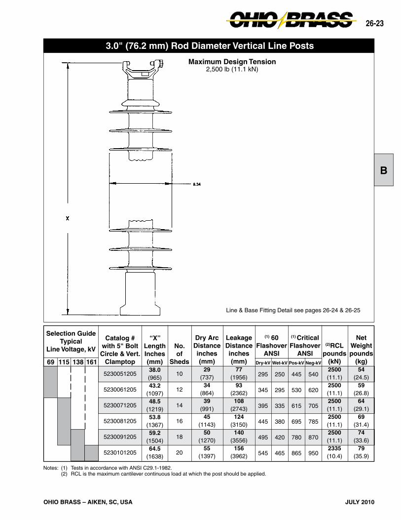
69 345230138 161115
Selection GuideTypical
Line Voltage, kV
Notes: (1) Tests in accordance with ANSI C29.1-1982. Electrical values are without corona ring. (2) RCL is the maximum continuous load at which the post should be applied. For voltages above 230 kV refer to Page 26-21 for Corona Rings. Electrical values are shown for insulators without rings. For electricals with rings, contact Ohio Brass.
Line & Base Fitting Detail see pages 26-24 & 26-25
Maximum Design Tension2,500 lb (11.1 kN)
3.0" (76.2 mm) Rod Diameter Vertical Line Posts
26-24
JULY 2010 OHIO BRASS – AIKEN, SC, USA
Horizontal & Vertical Bases Dimensions (in inches)
Type (Code)*
5" B.C. (05)
Al Gain (02)
Steel Gain (07)
Steel Flat (08)
Steel Flat (04)
A
6.36
14.0
14.0
13.0
14.0
B
5.9
17.0
17.0
15.0
17.0
C
4.37
-
-
9.0
-
E
5.0
7.75
7.75
6.5
7.75
F
-
5.949
7.03
4.12
4.12
D
1.2
8.079
9.65
11.0
10.0
G
-
0.53
0.5
0.5
0.5
H
-
14°
14°
14°
14°
I
5/8 - 11 UFS
1.06
1.06
0.938
-
J
-
1.06 x 2.56
1.06 x 2.56
-
1.06 x 2.56
Material
60-40-18 D.I.
6063 T5 Al
Low Carbon Steel
Low Carbon Steel
Low Carbon Steel
*Code is the 2nd number in the Suffix Code of the Catalog Number.
Steel FlatSteel Gain
Hi*Lite XL 3.0" Rod Dia. Base Fittings
Aluminum Gain 5" Bolt Circle
26-25
B
JULY 2010OHIO BRASS – AIKEN, SC, USA
*Code is the 2nd digit in the Suffix Code of the Catalog Number.
Vertical ClamptopPart per ANSI C29.7
Horizontal ClamptopPart per ANSI C29.7
Material
60-40-18 D.I.
60-40-18 D.l.
60-40-18 D.I.
B
5.63
5.63
5.63
A
6.16
8.64
6.31
Type (Code)*
2 Hole End (0)
H. Clamptop (1)
V. Clamptop (2)
C
3.84
3.84
3.84
D
0.75
1.12
1.12
E
6.12
4.72
5.37
F
1.57
4.0
4.0
G
2.0
-
1.06
H
2.5
-
-
I
-
5/8 - 11 UFS
5/8 - 11 UFS
J
1.44
0.75
-
K
1.24
-
-
L
0.5R
-
-
M
0.44 R
-
-
Horizontal & Vertical End Fittings Dimensions (in inches)
Two Hole Blade
Hi*Lite XL 3.0" Rod Dia. Line Fittings
26-26
JULY 2010 OHIO BRASS – AIKEN, SC, USA
Figure 2 Figure 4
Figure 1 Figure 3
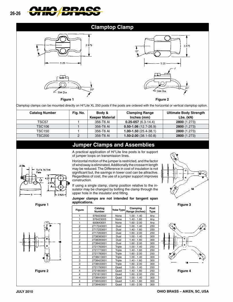
Clamptop Clamp
Jumper Clamps and AssembliesA practical application of Hi*Lite line posts is for support of jumper loops on transmission lines.
Horizontal motion of the jumper is restricted, and the factor of wind sway is eliminated. Additionally the crossarm length may be reduced. The Difference in cost of insulation is not significant but, the savings in tower cost can be attractive. Regardless of cost, the use of a jumper support improves construction.
If using a single clamp, clamp position relative to the in-sulator may be changed by bolting the clamp through the upper hole in the insulator end fitting.
Jumper clamps are not intended for tangent span applications.
Clamptop clamps can be mounted directly on Hi*Lite XL 250 posts if the posts are ordered with the horizontal or vertical clamptop option.
Dimension and Strength Ratings .................... 26-28Assembly Drawings ........................................ 26-29
26-28
JULY 2010 OHIO BRASS – AIKEN, SC, USA
Catalog number covers complete assembly including insulator and hardware as illustrated.
The need to minimize the tower size and visual impact of transmission lines has prompted increased interest in braced line posts, horizontal-V, and pivoting V assemblies. These insulating structures offer vastly improved vertical load capabilities over conventional lines posts while retaining the advantages of a fixed conductor position.
A braced line post uses a conventional line post with a sus-pension string tied to the tower face with a link. A horizontal-V replaces the link with a fixed offset extending from the tower face adding a stabilizing force to the assembly. Both these assemblies are available with flat or gain bases.
A pivoting horizontal-V assembly utilizes a line post insulator fastened to the structure with a hinged base. Alternatively, the base may be replaced with a universal joint.
These assemblies are available for voltages up to and includ-ing 345 kV with a wide variety of hardware to meet the needs of your application. The figures illustrated depict typical ar-rangements which provide an economical means of with-standing unusual loads. For more information on these and numerous other variations of line post assemblies, contact your Ohio Brass representative.
DIMENSIONS ANDSTRENGTH RATINGS
Suspension511010511211511013511014511018511219
BRACED LINE POST ASSEMBLYTypicalSystem
kV115/138115/138
161 161
230 *230 *
Cat #Gain Base
234220234222234224234226234228234230
Cat #Flat
Base234221234223234225234227234229234231
Post522008522009522010522011522014522015
Component Insulators
Vertical112801128011280112801128011280
Tension750075007500750075007500
Longitudinal17301550141012801020 960
Dimensions (in.) Maximum Loadings** (lb.)
A53.758.864.169.485.090.3
B72.881.991.197.2
121.6130.7
C74.083.091.096.0
118.0127.0
X222222
D79.888.998.1
104.2128.6137.7
Compres-sion
125001250012500125001181010470
Suspension511007511008511009511010511013511014
HORIZONTAL V ASSEMBLYTypicalSystem
kV115/138115/138
161 161
230 *230 *
Cat #Gain Base
234232234234234236234238234240234242
Cat #Flat
Base234233234235234237234239234241234243
Post522008522009522010522011522014522015
Component Insulators
Vertical998099809980998099809980
Tension750075007500750075007500
Longitudinal16801510137012501000 930
Dimensions (in.) Maximum Loadings** (lb.)
A54.960.165.570.986.992.3
B54.660.766.772.891.197.2
C51.056.061.066.080.085.0
X182022242830
D 61.6 67.7 73.7 79.8 98.1104.2
Compres-sion
125001250012500125001250012500
Suspension511007511008511009511010511013511014
PIVOTING HORIZONTAL V ASSEMBLYTypicalSystem
kV115/138115/138
161 161
230 *230 *
Cat #Gain Base
——————
Cat #Flat
Base234244234245234246234247234248234249
Post522008522009522010522011522014522015
Component Insulators
Vertical998099809980998099809980
Tension750075007500750075007500
Longitudinal——————
Dimensions (in.) Maximum Loadings** (lb.)
A55.260.465.871.287.292.6
B54.660.766.772.891.197.2
C51.056.061.066.080.085.0
X182022242830
D 61.6 67.7 73.7 79.8 98.1104.2
Compres-sion
125001250012500125001250012500
Contact your Ohio Brass representative for designs utilizing the optional pivoting strut member.* Corona rings are required for 230 kV and above.** Maximum loads are for single loads in the specified direction.
Hi*Lite® XL Assemblies
26-29
C
JULY 2010OHIO BRASS – AIKEN, SC, USA
OPTIONAL PIVOTING STRUT MEMBER
FLAT BASE MOUNTING
PIVOTING BASE MOUNTINGPIVOTING HORIZONTAL-V
BRACED LINE POST HORIZONTAL-V
GAIN BASE MOUNTING
Assembly Drawings
26-30
JULY 2010 OHIO BRASS – AIKEN, SC, USA
26-31
D
JULY 2010OHIO BRASS – AIKEN, SC, USA
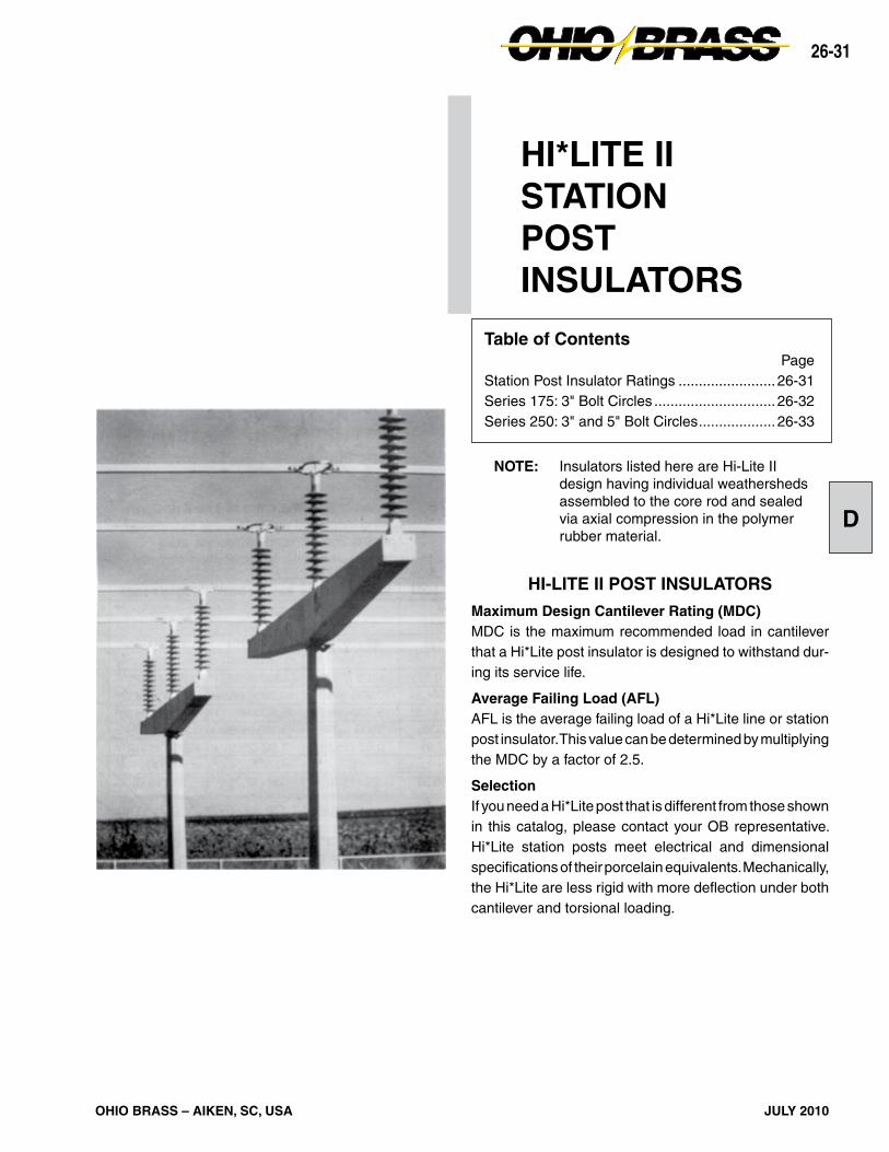
HI-LITE II POST INSULATORS
Maximum Design Cantilever Rating (MDC)MDC is the maximum recommended load in cantilever that a Hi*Lite post insulator is designed to withstand dur-ing its service life.
Average Failing Load (AFL)AFL is the average failing load of a Hi*Lite line or station post insulator. This value can be determined by multiplying the MDC by a factor of 2.5.
SelectionIf you need a Hi*Lite post that is different from those shown in this catalog, please contact your OB representative. Hi*Lite station posts meet electrical and dimensional specifications of their porcelain equivalents. Mechanically, the Hi*Lite are less rigid with more deflection under both cantilever and torsional loading.
HI*LITE IISTATIONPOSTINSULATORS
Table of ContentsPage
Station Post Insulator Ratings ........................ 26-31Series 175: 3" Bolt Circles .............................. 26-32Series 250: 3" and 5" Bolt Circles ................... 26-33
NOTE: Insulators listed here are Hi-Lite II design having individual weathersheds assembled to the core rod and sealed via axial compression in the polymer rubber material.
26-32
JULY 2010 OHIO BRASS – AIKEN, SC, USA
Note: Station Posts are also available in non-standard section lengths. Contact your Ohio Brass representative.
CATALOG NUMBER (3" BOLT CIRCLES)BIL (kV)Height — X in. (mm)Leakage Distance in. (mm)60-Hz Withstand — 10 sec/wet (kV)Maximum Design Cantilever lb. (kN)Maximum Design Tension lb. (kN)Maximum Design Compression lb. (kN)Maximum Design Torsion in.-lb. (N-meter)Deflection at Stated Cantilever in. (mm)WeathershedsNet Weights lb. (kg.)
HI*LITE II STATION POST INSULATORSSeries 1753" (76mm) Bolt Circles
NOTE: Insulators listed here are Hi-Lite II design having individual weathersheds assembled onto the core rod and sealed via axial com-pression in the polymer shed material.
Notes: 1. Station Posts are also available in non-standard section lengths. Contact Ohio Brass. 2. At 230 kV, corona ring 2721273001 may be required. 3. For through holes, specify code 3002.
CATALOG NUMBER (5" BOLT CIRCLES)BIL (kV)Height — X in. (mm)Leakage Distance in. (mm)60-Hz Withstand — 10 sec/wet (kV)Maximum Design Cantilever lb. (kN)Maximum Design Tension lb. (kN)Maximum Design Compression lb. (kN)Maximum Design Torsion in.-lb. (N-meter)Deflection at Stated Cantilever in. (mm)WeathershedsNet Weights lb. (kg.)
2323753001900
80 (2032)204 (5180)
560990 (4.45)
30,000 (133) 35,000 (156)9,000 (66.7)13.50 (343)
2272 (32.7)
CATALOG NUMBER (3" BOLT CIRCLES)BIL (kV)Height — X in. (mm)Leakage Distance in. (mm)60-Hz Withstand — 10 sec/wet (kV)Maximum Design Cantilever lb. (kN)Maximum Design Tension lb. (kN)Maximum Design Compression lb. (kN)Maximum Design Torsion in.-lb. (N-meter)Deflection at Stated Cantilever in. (mm)WeathershedsNet Weights lb. (kg.)
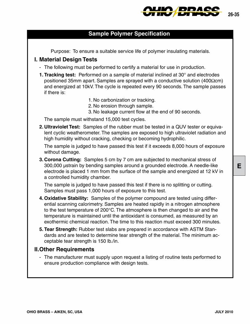
Purpose: To ensure a suitable service life of polymer insulating materials.
I. Material Design Tests - The following must be performed to certify a material for use in production.
1. Tracking test: Performed on a sample of material inclined at 30° and electrodes positioned 35mm apart. Samples are sprayed with a conductive solution (400Ωcm) and energized at 10kV. The cycle is repeated every 90 seconds. The sample passes if there is:
1. No carbonization or tracking. 2. No erosion through sample. 3. No leakage current flow at the end of 90 seconds.
The sample must withstand 15,000 test cycles.
2. Ultraviolet Test: Samples of the rubber must be tested in a QUV tester or equiva-lent cyclic weatherometer. The samples are exposed to high ultraviolet radiation and high humidity without cracking, checking or becoming hydrophilic.
The sample is judged to have passed this test if it exceeds 8,000 hours of exposure without damage.
3. Corona Cutting: Samples 5 cm by 7 cm are subjected to mechanical stress of 300,000 µstrain by bending samples around a grounded electrode. A needle-like electrode is placed 1 mm from the surface of the sample and energized at 12 kV in a controlled humidity chamber.
The sample is judged to have passed this test if there is no splitting or cutting. Samples must pass 1,000 hours of exposure to this test.
4. Oxidative Stability: Samples of the polymer compound are tested using differ-ential scanning calorimetry. Samples are heated rapidly in a nitrogen atmosphere to the test temperature of 200°C. The atmosphere is then changed to air and the temperature is maintained until the antioxidant is consumed, as measured by an exothermic chemical reaction. The time to this reaction must exceed 300 minutes.
5. Tear Strength: Rubber test slabs are prepared in accordance with ASTM Stan-dards and are tested to determine tear strength of the material. The minimum ac-ceptable tear strength is 150 lb./in.
II. Other Requirements- The manufacturer must supply upon request a listing of routine tests performed to
MEXICOHUBBELL DE MEXICO, S.A. DE C.V.Av. Insurgentes Sur #1228, Piso 8Col. Tlacoquemacatl Del ValleMexico, D.F. 03200Phone: 52-55-9151-9999Fax: 52-55-9151-9988Website: hubbell.com.mx
UNITED STATESCANADA, INTERNATIONALHUBBELL POWER SYSTEMS, INC.210 N. Allen Street Centralia, Mo 65240-1395Phone: 1-573-682-5521Fax: 1-573-682-8714e-mail: [email protected]