ʽþxnÖ ùºiÉÉxÉ +Éì MÉæ ÊxÉEò Eä òʨÉEò±ºÉ ʱÉʨÉ]ä õb÷ HINDUSTAN ORGANIC CHEMICALS LIMITED (A Govt. of India Enterprise) COCHIN UNIT, AMBALAMUGAL, Phone No.-2720911-14, Fax No.-2720893, Web site – www.hoclkochi.com e-mail – [email protected], [email protected]NOTICE INVITING QUOTATIONS Enquiry.No : HOC/LNG/001/12 Date : May 18, 2012 Dear Sirs, 1. Sealed quotations in duplicate are invited by Chief General Manager (Production & Engineering), Hindustan Organic Chemicals Ltd., Ambalamugal for the works as detailed below. A set of tender document is enclosed for submitting your quotation. 2. Name of Work:Conversion of 2 Nos. Main Boilers for Dual Fuel Firing (R-LNG & FO) .A brief description of the scope of works given separately in which is attached herewith. 3. Last Date of Receipt of Quotations : Tenders will be received at the office of General Manager (P&A), Hindustan Organic Chemicals Ltd., Ambalamugal on or before 18/06/2012 up to 14.00 hrs. Bids received after the due date will not be considered. 4. Earnest Money Deposit : Quotation shall accompany an EMD of ` ` `1,25,000/ 1,25,000/ 1,25,000/ 1,25,000/- - - paid by crossed DD/Bankers Cheque/Cash only of State Bank of India drawn in favor of M/s. Hindustan Organic Chemicals Ltd., payable at Ambalamedu branch of SBI. Quotations not accompanied with EMD, are liable to be rejected. 5. Time of Completion :The time of completion of the work will be 210days from the date of issue of work order or issue of instructions to start the work. (Please see the scope of work). 6. Cost of Tender Documents : NIL 7. Submission of Quotations 7.1.a. Bidders shall submit their offer in TWO SEPARATE SEALED ENVELOPES. ENVELOP No: 1 is to be addressed and superscribed as UNPRICEDBID and the name and address of the bidder and to contain the Earnest money and signed in all pages of the offer and details asked for, for pre qualification along with a forwarding letter containing all schemes with all technical details and technical & commercial deviations if any. ENVELOP NO: 2 to be addressed and super scribed as PRICED BID and to contain price alone and signed in all pages.
1.1. HOCL has 2 main boilers of 24.5 TPH capacity at Phenol Complex in Kochi, Ambalamugal.
1.2. The main boilers are fired by LSHS / Furnace Oil (FO)
1.3. In view of the availability of R-LNG (Re-gasified LNG) at Kochi, HOCL proposes to modify the boilers so as to enable firing of R-LNG as well as FO (dual fuel). Simultaneous firing of R-LNG and FO is not envisaged.
1.4. HOCL intends to carry out the conversion of the 2 boilers in stages. Conversion shall be carried out one boiler after the other. One boiler will be on line. The common works can be completed during shut down March 2013.
2. DESCRIPTION OF EXISTING SYSTEM
2.1. BOILER DETAILS
BOILER REGISTRATION No. Boiler – 1 K – 479 Boiler – 1 K - 480
2.2. HOCL operates two boilers of 24.25 TPH capacity (after revamp in 2005) (one at a time) steam pressure of 20 kg/cm2 (g), steam temperature of 214°C (saturated) and with feed water temperature of 145°C.
2.3. The boilers supplied & commissioned in 1983-84 by M/s. WIL (M/s. Walchandnagar Industries Ltd.) are having bi-drum arrangement with bank tubes and side wall firing. The control system was upgraded from pneumatic controls to DCS in the year 2003.
2.4. The boiler was revamped by replacing the burners with new burners (PLC for burner management system), FD & ID fans were provided with VFD, SCAPH (steam coil air pre-heater) was introduced in the combustion air system, and a feed water heater was introduced before the economiser. This revamp was done by M/s TBW in the year 2005.
2.5. The Boiler Economiser is arranged as a separate unit connected by duct bank tubes. The boilers are provided with forced draft system (FD Fan). The SCAPH (Steam Coil Air Pre Heater) (Tubular fin type) is provided in the air side after the FD fan. A common chimney is provided for two boilers.
2.6. Each of the boilers are fitted with Two nos. 16 ½” oil fired - Industrial circular type burners of Thermax Babcock & Wilcox make on the side wall panel of the boiler over the wind box. The ignitor and the oil guns are fitted with flame monitors (UV & IR) which are cooled by compressed air and remote operated shut off valves for supervision and control by the Burner Management System (BMS) to ensure safety during light up and operation and connected to a common windbox arrangement for the air supply to the burners. Vendor has to study the present combustion air system (including FD fan, SCAPH and ducting) for its suitability for maximum and minimum load operation. In case of R-LNG, if pre-heating of air is not required, a provision for SCAPH by-pass duct with damper arrangement for both boilers shall be considered.
2.7. The oil gun is ignited using LPG / gas ignitor. LPG to the ignitor / Pilot gas is supplied from LPG cylinder through a 15 NB Stainless steel pipeline.
2.8. Details / specifications of the boilers are tabulated below:
Equipment Details Description /Values No. of Boilers 2 Nos. Supplier M/s. WIL, Pune Reg. No. K–479 & K–480 Furnace width 3060 Furnace depth 4400 Draft type Forced draft (1 No. FD Fan per unit) Boiler Parameters Steam Flow (100% MCR) 24.25 TPH per unit (after revamp in 2005)Steam Pressure 20 Kg/cm2
Steam Temperature 214°C (saturated) Boiler Feed Water Temperature 145°C
2.9. Details of Burners are given below: MAKE THERMAX BABCOCK & WILCOX LTD.MODEL Oil Fired Industrial Circular burnerSize & Type of Boiler 16.5” standard circular oil burnerNo. of burners per boiler 2No. of oil gun provided in each burner 1 No. main gun
Type of air control & accessories Lead lag arrangement (Existing), Annular at SCAPH outlet.
Oil Gun Atomizer I jet Swirler/Impeller information Impeller Fuel Fired LSHS / FO Oil pressure at tip inlet at peak (psi) 120 Diff. Steam Pressure at tip at peak 20 (psi) Atomising Media Steam Pressure at Burner (max) Kg/cm2 (g) 10 Steam Temp. at burner inlet Deg C 201 (MAX) Burner Turndown 1:4 (auto) Fuel for Igniter LPG Pilot gas pressure 1 Kg/cm2 Quantity of Fuel fired in Pilot Gun 30 Nm3/hr (approx.) No. of Flame Scanners / Type 2 No. for per Burner, Type:IR/UV Minimum Distance from Burner c/L to another burner c/l(Horizontal/Vertical)
Horizontal-0 Vertical-1286
Windbox Common for both burners
Burner location Burners are mounted on sidewall of the boiler. Two burners at same elevation.
Excess air at burner % @ design heat release rate
15 %
Total air required all burner Kg/hr 23390 Air req. per burner Kg/hr& Temp. 11695, @ 110 Deg C Burner pressure drop mmwg 120 Fuel requirement @ 100% MCR 1500 Kg/Hr. (2 Burners in operation)
2.10. Forced Draft (FD) Fan Specification.
The vendor has to ensure that present system (including FD fan, SCAPH and ducting is suitable for maximum and minimum load operation)
Volumetric Flow Rate 6.22 M3/Sec Gas temperature 30 °C Gas Density 1.16 kG/m3
Pressure Rise 191 Mm WG Fan Speed 1610 RPM Motor power 22 kW Type of Control Inlet vane control & VFD Drive Belt Drive
2.11. Induced Draft (ID) Fan Specification. The vendor has ensure that present system (including FD fan, SCAPH and ducting is suitable for maximum and minimum load operation)
Volumetric Flow Rate 9.0M3/Sec Gas temperature 145 °C Gas Density 0.841kG/m3 Total Pressure 161 MM WG Fan Speed 200 RPM Motor power 55 kW Type of Control Inlet damper control & VFD Drive Belt Drive
2.12. Design Specification of Fuel Oil
Type LSHS / LSFO Gross Heating Value 9500 Kcal/Kg Oil Viscosity required at the oil gun 15 -20 centistokes Oil flow per burner @ MCR 1500 Kg/h Oil pressure required at burner for MCR 10 Kg/cm2 (g)
2.13. Remaining Life Assessment (RLA) of the 2 boilers as per Table 1 of IBR regulation 391A was carried out by M/s. Central Power Research Institute during 2010 and the boilers certified “Fit for continued operation at the rated pressure for a period of five years.
3. SPECIFICATION OF NATURAL GAS (R - LNG) The tentative specification R - LNG is as follows:
3.1. Composition in Mol %
C1 Methane
C2 C3 C4 C5 C6 CO2 N2 H2S
88.00% min.
1.50 to 6.00%
3.50% max.
2.00% max.
0.10% max.
NIL 100 ppm
1.00% max.
5.0 mg/NM3
3.2. Properties & Battery limit conditions
Gross Calorific Value (GCV) – range 9340 (min) / 10,420 (max) Kcal / Std. M3
Specific Density 0.65 (w.r.t. air at ATP) Molecular weight 18.29 Pressure at Battery Limit 12 Kg/cm2
Temperature at Battery limit At ambient temperature i.e.( ~30°C)
4. BATTERY LIMITS
The following battery limits shall apply for each boiler and all necessary items/ connections from and up to these limits are covered under the scope of this work.
Description Battery Limit R-LNG At a distance of 1 Mt. from boiler House building.
FO / LSFO Downstream of first isolation valve from the common header to the boiler.
LPG Downstream of first isolation valve from the common header to the boiler.
Combustion Air Provided to the windbox near the burners. The vendor has to ensure the suitability of the present system (including FD fan, SCAPH and ducting).
Atomizing Steam After first isolation valve from the common header to the boiler. Steam supply from boiler
Upstream of Main Steam Stop Valve.
Flue Gas Outlet of Economizer.
Instrument Air At a distance of 5.0 Mts. from boiler, after supply isolation valve.
Steam for Soot Blowing
After first isolation valve of the Soot Blowing steam inlet.
The party shall visit our site before quoting to ascertain the location of first isolation valves / ducting and the quantum of work involved.
5. SCOPE OF WORK
The scope of work of the vendor includes but not limited to the following:
5.1. Study of the existing system and firming-up of modifications required to carryout the conversion so as to enable firing of R-LNG as well as LSHS / FO for the two main boilers K-479 & K-480 on turnkey basis. The modifications shall include all the conditions arising due to dual firing so as to ensure the continuous safe and reliable operation of the boilers at design condition and conformity to statutory and safety norms / regulations.
5.2. To study the existing combustion air system (including FD fan, SCAPH, ducting, head loss, and its controls) for its suitability for maximum and minimum load operation firing with FO / LSHS & R-LNG.
5.3. The proposed burners shall be designed for FO / LSHS & R-LNG as per specifications given.
5.4. The proposed burners for Boiler – 1 and Boiler – 2 shall be horizontal, side wall mounted type, steam atomized; 2 Nos. burners per boiler in one tier, designed to meet 110% MCR capacity at peak loads.
5.5. Detailed Engineering of the modifications and submission of drawings, data sheets, and design calculations for review and approval by HOCL. Site dismantling and modification works (mechanical/Instrumentation/Electrics). All dismantling and modifications / retrofit of the boiler pressure components shall conform to the requirements of Indian Boiler Regulations (IBR).
5.6. Design and supply of common pressure reducing station & bypass for fuel (R-LNG) with PSV, isolation valves, control valve and globe valve including the required instrumentation for control as per the relevant standard.
5.7. Design / selection and supply of Dual Fuel Burners for each boiler.
5.8. Design / selection and supply of New FD Fan and motor with VFD (if required) with flow control (one No for each boiler) suitable for maximum and minimum steam load operation, firing with FO / LSHS & R-LNG after considering the pressure loss
due to SCAPH, Ducting, wind box etc. In case of R-LNG, if pre-heating of air is not required, a provision for SCAPH by-pass duct with damper arrangement for both boilers shall be considered. Design of all piping systems shall be as per ANSI / ASME B 31.3 and All boiler feed water and steam lines shall be as per the latest issue of IBR and ANSI / ASME B31.1, Flange and valve ratings shall be as per class designation in ANSI B16.5 and ANSI B16.34 respectively
5.9. Supply of all materials and bought – out items including steel plates, structural, supports, tubes refractory material, etc.
5.10. Fabrication / modification of the existing boiler components (if required) as per IBR code (pressure parts) / good engineering practices (non pressure parts).
5.11. Site supervision for dismantling, modification, erection, commissioning and performance testing.
5.12. Obtaining statutory approvals (IBR)
5.13. Inspection and testing of the components as per IBR requirements.
5.14. Transportation of the components to site including Transit Insurance, unloading etc.
5.15. Loading and unloading of the components (requiring replacement) from the existing boilers and transporting of these components to the scrap yard located within 1.0 Km from the boiler.
5.16. Erection of the components at site.
5.17. Design, supply and application of Refractory lining for the burner throat / modified area.
5.18. Supply and application of Insulation and Cladding as necessary. Lightly resin bonded mineral wool mattresses shall meet the requirements of IS 8183. The amount of resin added shall be between 1% to 3% by weight. The insulation material shall be rated as non-combustible and shall be tested in accordance with IS 3677 & IS 8183 or IS 3114 as applicable.
5.19. Painting of equipment including supply of painting materials.
5.20. Supply and erection of all piping, pipe fittings, pipe support etc. within the battery limit.
5.21. Fabrication and erection of structural supports, ladders and platforms as necessary.
5.22. Refractory drying out of the reworked portion etc.
5.23. Commissioning of the boiler after hook-up.
5.24. Conducting trial run and guarantee run (with all required calibrated measuring gadgets and instruments) of the equipment, for 72 hrs after stabilization of the plant at rated capacity.
5.25. Supply of spares for trouble free operation for two years to be supplied. (to be given as separate attachment).
5.26. Submission of final documentation.
5.27. All the above works shall be carried out on a turnkey basis.
6. DUTY CONDITIONS
6.1. The modified boiler shall be designed to meet the following duty conditions:
Steam Flow (100% MCR) : 24.25 TPH per boiler
Steam Pressure : 20 Kg/cm
Steam Temperature : 214°C (saturated)
Burner Turndown : 1 : 4
6.2. The flue gas composition at stack exit (for FO as well as R-LNG firing) shall meet the Kerala State Pollution Control Board Norms.
7. CODES & STANDARDS
The following codes / standards are applicable
7.1. Indian Boiler Regulations (IBR) 7.2. Kerala State Pollution Control Board (KSPCB Norms) 7.3. NFPA – National Fire Protection Association 7.4. IS-8753 – Boiler Efficiency testing
8. GENERAL
8.1. Platforms, ladders and other structural necessary for the proper access to the various headers, manholes /hand holes, valves, instruments etc. shall be provided.
8.2. No extra claim will be entertained for any changes, which may arise during detailed engineering.
9. INDIAN BOILER REGULATION AND APPROVALS
9.1. All accessories, fittings and instruments required as per IBR shall be provided.
9.2. All equipments and parts covered under Indian Boiler Regulation shall be designed, fabricated, tested and erected as per the requirements of this Regulation and necessary statutory approvals obtained.
9.3. All necessary certificates in the specified forms as required by the Boiler Inspectorate shall be forwarded to HOCL. Responsibility of the owner with respect to the Boiler Inspectorate is limited to paying the registration fees and forwarding of necessary application forms only.
9.4. All activities related to obtaining approval and clearance by the IBR and other statutes shall be the responsibility of the vendor.
10. INSULATION AND REFRACTORY LINING
10.1. Wherever required, the boiler shell and steam lines shall be refractory lined / insulated taking into consideration personnel protection and energy conservation as per the relevant code.
10.2. Exposed hot surfaces shall be provided with thermal insulation.
10.3. Supply and application of refractory lining / insulation including metal cladding is in the vendor’s scope.
11. PAINTING
11.1. Painting of external surfaces of components (including platforms, ladders, pipe supports, handrails, etc) is in vendor’s scope and shall be as per attached specification.
12. SPARES
12.1. Essential spares required during commissioning shall be included in the scope of supply of the vendor. Spares for two years trouble free operation of the system shall be quoted for, separately in the Tender. Vendor shall furnish the list of spares envisaged in the offer showing rate and amount for each item.
12.2. Special tools, if any, required for maintenance shall also be included in the vendor’s scope.
13. INSPECTION
13.1. Testing of all materials shall be as per relevant codes / standards / specifications.
13.2. HOCL shall have free access to the work site of the vendor or his subcontractor (if any) to carryout the inspection of items covered under the scope of work.
13.3. Approval of work by HOCL shall in no way relieve the vendor of responsibility in meeting all these provisions of the enquiry conditions.
14. SUB-VENDORS / SUB-CONTRACTORS
14.1. For works / supplies to be carried out by sub-vendors, vendor shall obtain prior approval from HOCL regarding the scope of such works and the parties to whom such sub-contracting is proposed.
15. ERECTION, HOOK-UP AND COMMISSIONING
15.1. The modifications to the boilers shall be carried out in a staggered manner (one boiler at a time) and without causing any hindrance to the normal operation of the plant. One boiler will be in operation.
15.2. The modifications, erection at site, start up and commissioning of the first boiler shall be completed within 60 days of handing over of the boiler.
15.3. After achievement of the performance / guarantee requirements and stabilized running of the first boiler for a period of 60 days, the second boiler shall be handed over for the required modifications.
15.4. The modifications, erection and commissioning of the second boiler shall be completed within 45 days of handing over the first boiler.
15.5. All the works requiring the shutdown of both the boilers together (if required) shall be done during March-April 2013 and shall be completed with 15 days from the handing over of the boilers.
16. GUARANTEE
16.1. PERFORMANCE GUARANTEE
Vendor shall ensure that the modified boilers meet the following performance guarantees individually for both R-LNG and FO firing.
Parameter Fuel Normal Tolerance a. Steam pressure FO / R-LNG 20 Kg/cm2(g) +/ - 0.5 Kg/cm2
b. Steam flow FO / R-LNG 24.25 TPH - 0.0 TPH c. Fuel (R-LNG)
consumption, @MCR conditions
R-LNG Thermal equivalent of fuel consumption per MT of steam generated after fuel changeover to RLNG shall not exceed the thermal equivalent of fuel consumption per MT of steam generated by firing FO before changeover. For calculating the thermal equivalent of fuel, Net Calorific Value (NCV) of the respective fuels shall be used.
+ 2.0%
16.1.1 The parameters of steam pressure and steam flow listed above shall be guaranteed for both R-LNG and FO.
16.1.2 Separate guarantee runs shall be carried out for R-LNG and FO firing
16.1.3 Duration of guarantee runs shall be 72 hrs for R_LNG and that for FO shall be 24 hrs. minimum
16.2. MECHANICAL GUARANTEE
16.2.1. Vendor shall guarantee the equipment / components of the boiler against all defects in design, use of defective materials or bad workmanship, for a period of 12 months from the date of commissioning or 24 months from the date of supply whichever is earlier. During the guarantee period any such defects noticed shall be set right by the vendor at his own cost within a period of 3 weeks.
16.2.2. During Performance Guarantee run and subsequent running of the boilers in R-LNG /FO within the guarantee period prescribed, no part of the boiler shall be subjected to temperatures beyond the permitted limits, distress, etc. by virtue of improper design, construction of burners or other reasons attributed to the vendor and covered in vendor’s scope of work. During the guarantee period such defects noticed shall be set right by the vendor at his own cost.
17. PENALTY
17.1. Capital cost: Capital cost of conversion of each boiler is defined as the total amount for design /engineering, supply, erection, commissioning, performance run, spares, contingency / escalation (if applicable), etc, for conversion of the boilers.Total Capital cost: The Capital cost of both boilers added together
17.2. PENALTY FOR SHORTFALL IN PERFORMANCE
17.2.1. The following penalty clauses shall apply for shortfall in performance. Also clause given below shall be guaranteed for both R-LNG and FO in separate guarantee runs and penalties shall be correspondingly applied separately for R-LNG and FO.
17.2.2. If the vendor fails to achieve the same even after the rectifications within a reasonable period or if in the opinion of HOCL, the vendor is unable to do so or the repair/replacement cannot wait till the vendor is able to do it, HOCL may either directly or through such other agencies as HOCL may deem fit, get the defective part made good or carry out the repair/replacement, all at the risk and cost of the vendor.
17.2.3. Any decrease of the steam pressure from the applicable measurement tolerance limit of 19.5 kg/cm2 or increase of the steam pressure from the applicable measurement tolerance limit of 20.5 kg/cm2, shall be rectified by the vendor at his own cost to achieve the guaranteed figure. If the vendor fails to achieve the same even after the rectifications, the provision vide 17.2.2 shall apply.
17.2.4. TPH decrease in steam output from the applicable measurement of 24.25 TPH is not allowed. If it is below this limit, the equipment shall be rectified by the vendor at his own cost to achieve the guaranteed figure. If the vendor fails to achieve the same even after the rectifications, the provision vide 17.2.2 shall apply.
17.2.5. Penalty for guaranteed Thermal Equivalent of fuel consumption at MCR conditions a) Prior to handing over each boiler for conversion, the boiler shall be run on FO
for 72 hours at MCR conditions or the maximum steam load possible; in case there is any load restriction for that boiler, at a steady conditions as possible and the thermal equivalent of fuel consumption required to generate unit quantity of steam (MT) at duty conditions of pressure and temperature shall be computed.
b) After conversion to R-LNG, the boiler shall be run on R-LNG for 72 hours at MCR conditions at nearly same conditions as in the pre-run as possible and the thermal equivalent of fuel consumption in R-LNG required to generate unit quantity of steam (MT) at duty conditions shall be computed.
c) For every 0.20 % increase in the thermal equivalent of fuel consumption per unit steam quantity (MT) in R-LNG above the thermal equivalent of fuel consumption per unit steam quantity (MT) in FO (LCV / LHV basis), 1.0 % (one percent) of the capital cost of the affected boiler shall be paid by the vendor as liquidated damages up to a maximum limit of 2.0 %. If it exceeds the limit of 2.0 %, the equipment shall be rectified by the vendor at his own cost to achieve the guaranteed figure. If thevendor fails to achieve the same even after the rectifications, the provision vide 17.2.2 shall apply.
17.2.6. The maximum penalty for shortfall in performance for both boilers shall be limited to 10.0% (ten percent) of the total capital cost, of both boilers and shall be independent of any other penalties specified elsewhere in the bid / enquiry document.
18. VISIT TO SITE
18.1. Vendor shall visit the site and acquaint himself with the details of the equipment and site conditions, before submitting his offer.
19. OBLIGATIONS BY OWNER 19.1. HOCL will provide necessary office space and storage space. Vendor’s requirements
shall be indicated in the offer. 19.2. Water and electricity will be provided at one point, free of cost. Vendor to arrange
for distribution box with ELCB etc. 19.3. Crane / Forklift facility will be provided by HOCL depending on availability, on
chargeable basis. Non supply of crane at any point of time by HOCL cannot be cited as a reason for any delays in execution. The vendor has to make his own arrangements if HOCL facilities are not available.
20. EXCLUSIONS The following items / activities are excluded from the vendor’s scope.
20.1. All foundations for equipment and buildings and other civil works unless otherwise stated are excluded from the scope of the vendor. Civil scope drawings with loading data and foundation details shall be furnished by vendor well in advance.
21. SUB VENDORS LIST 21.1. The sub vendor list for certain critical items for RLNG modification work is as
Vendor shall furnish the following along with his offer. (Technical Bid) without which his offer shall not be considered for further evaluation.
22.1. (Annexure-1) & (Annexure-2) duly filled. 22.2. Duly filled format for spares. 22.3. All other documents required to be submitted along with the offer.
INSTRUMENTATION REQUIREMENTS
1.1 All additional instrumentation, erection material such as junction boxes, cables, pipe and tube fittings, field erection and also cabling from/ to marshalling and field/ other locations outside the control room shall be in the scope of the vendor.
1.2 The existing control system itself is envisaged for interlocking, continuous control and operator interface.
1.3 The scope of work includes but not limited to
• Design of the Instrumentation system for boilers with combination of LNG and fuel oil firing.
• Furnish hazardous area classification drawing/ details (arising due to LNG conversion of Boiler system)
• Supply of additional field instruments including cables, cable glands, perforated Al cable trays, Junction Box and other erection materials like ferrules etc if any required.
• Erection/Installation of instruments, Junction boxes, laying of branch cables in the field up to the Junction boxes and main cables up to marshalling box in the control room.
• Calibration of the instruments covered in the modification.
• Termination and loop Checking in co-ordination with HOCL personnel.
• Associate with DCS/ PLC vendors & HOCL for the implementation of interlocks and configurations of I/O in PLC and DCS
• Commissioning of the complete system.
• Guarantee run for the instruments.
• Training & documentation as required for the operating & maintenance personnel.
1.4 The vendor shall propose the additional instruments required for the modification and submit the complete BOM. The selection of the instruments shall be based on the Instrument Design/ Installation Philosophy, given at the end of this chapter as applicable. Instruments and junction boxes selected shall be suitable for the hazardous
area classification details proposed by the Vendor (considering the changes arising due to LNG conversion of Boiler system). It may be noted that, presently, all the transmitters are explosion proof but other field Instruments are not explosion proof.
1.5 Any other specific requirement for meeting the process requirement which is not available in the existing system has to be included by the vendor in his scope of supply and work for completion, to the satisfaction of HOCL Kochi.
2.0 EXISTING SYSTEM DETAILS:
2.1 CONTROL SYSTEM (DCS)
The existing control system is the latest Yokogawa Centum CS3000 DCS system installed in 2009. There are 448 I/O’s in DCS System. The analog inputs and outputs shall be of 4-20 mA DC loop powered type. T/C cards are Universal type. The present installed capacity (spare capacity) of the system is as follows.
I DCS SYSTEM
Sl.No. Item Capacity (Nos.)
Used (Nos.)
Spare (Nos.)
1 Analog inputs (Red) 56 33 23
2 Analog Inputs (non Red) 96 33 63
3 Analog Output 56 34 22
4 Digital Inputs 128 28 100
5 Digital Output 96 22 74
6 T/C inputs 16 11 5
Present analogue control schemes configured in the DCS are given in Annexure I-1
2.2 INTERLOCK SYSTEM (PLC)
The existing system for sequential/safety interlock operations is Allen Bradley PLC (Micrologix 1200 Series C) installed in year 2006. There are 192 I/O’s in PLC System. The present installed capacity (spare capacity) of the system is as follows.
Present analogue control schemes configured in the DCS are given in Annexure I-1
II PLC SYSTEM
Sl.No. Item Capacity (Nos.)
Used (Nos.)
Spare (Nos.)
Boiler 1 Digital Inputs 64 56 8
Digital Outputs 32 23 9
Boiler 2 Digital Inputs 64 56 8
Digital Outputs 32 23 9
3.0 DETAILED SCOPE OF WORK
3.1 The detailed scope of work of the vendor relating to system shall be as follows.
3.2 The existing control system including hardwired consoles and panels of DCS and PLC has to be retained. The modifications required is incorporation of the new Inputs and Outputs related to LNG conversion and incorporation of new logics and control schemes in the existing DCS and PLC system.
3.3 The existing control schemes in DCS and BMS sequence logic in PLC is given in the Annexure-I attached. Vendor shall study the existing system and propose the modifications required for the LNG conversion and submit the modified control schemes and logics to HOCL. The logic shall be developed such that all the prevailing safety standards and regulatory and statutory requirements are met and also the existing philosophy is followed as far as possible. The vendor shall also supply the list of additional I/O's required in DCS and PLC for the LNG conversion. All the Integration of the LNG related Inputs and Outputs to the Existing control system shall be done by HOCL through M/s Yokogawa India for DCS and through M/s Allen Bradley for PLC.
3.4 All the system configuration related to PLC & DCS will be done by HOCL, in co-ordination with M/s Yokogawa India for DCS and M/s Allen Bradley for PLC, exactly as per the modified control schemes and logics submitted by the Vendor. The overall system integration and seamless smooth operation shall be the responsibility of the vendor.
3.5 For the case of PLC system redundancy is to be provided based on the prevailing safety standards and statutory requirements, if any applicable. (Existing PLC is not redundant)
3.6 All the digital inputs are of potential free type and the interrogation voltage is 24 VDC. The Digital out put for boiler plant is 110 V AC. Interposing relays are provided for all digital inputs and out puts for DCS. Interposing relays are provided for all digital out puts for PLC. The indication lamps in HWC are of 24 V DC.
4.0 FIELD INSTRUMENTATION
4.1 Field instrumentation: general
4.1.1 All field transmitters supplied shall be compatible with Yokogawa Centum CS3000 DCS the system.
4.1.2 Mass flow meters (coriolis) shall be provided for RLNG input to each boiler. 110V AC, 50 Hz shall be the supply voltage and output shall be 4-20 mA.
4.1.3 The types/makes of instruments shall be kept to the minimum possible in order to have uniformity, interchangeability and low inventory.
4.1.4 ¼” & ½” OD SS316 tubes & 1/2” SS pipes with SS316 fittings in ¼” & ½” NPT threading to be provided as per existing philosophy at site.
4.1.5 All types Instrument clamps selected shall be SS316 in general. Stanchions shall be MS pipe, 2” OD, and 1350 mm height.
4.1.6 Temperature elements shall be of K-type. Temperature gauges shall be Bimetallic type.
4.1.7 All Instruments and accessories including cables, junction boxes, different type of cable glands (suitable to the OD of cables), shall meet the area classification proposed by the vendor.
4.1.8 Quality crimping lugs and tools to be arranged for perfect termination. Printed single tubular ferrules to be used for ferruling of wires.
4.1.9 Similarly for the Instrument erection related materials like perforated aluminium cable trays, structural materials, tube and pipe fittings also shall be supplied and erected by vendor.
4.2 Tappings
4.2.1 Pressure, temperature tappings and test pockets for RLNG piping as per the vendor scheme to be provided. All threaded thermo wells shall be seal welded.
4.2.2 Local temperature and pressure gauge tappings shall be provided as per vendor scheme. Similarly, for pressure and temperature switches also.
4.2.3 Separate tapping points with isolation and drain facility shall be provided for each field instrument as per the relevant schemes.
4.2.4 Separate tapping points with isolation and drain facility shall be provided for each of the field instruments.
4.3 Cables, Junction Boxes, etc.
4.3.1 Special cables Recommended for flame scanners to be used, DS to be furnished for approval.
4.3.2 12 P x 1.5 mm 2 shall be used for cabling between JB and control room (PLC/DCS)
4.3.3 2P x 1.5 mm2 cable for the signals between instrument and Junction box. (4-20 mA and digital signal 24VDC/110VAC).
4.3.4 Yellow outer sheath, K-type T/C extension cable shall be used as per the case to meet the site philosophy as per ANSI/MC96.1
4.3.5 All cables to be properly tagged using SS tags
4.3.6 The field instrumentation shall be generally as per the existing philosophy. All instruments and cable and junction boxes shall meet the area classification recommended by vendor.
4.3.7 The supply, Installation, cabling, termination, testing of all instruments at the field instrument, JB and at the control room with the modification scope of work has to be done by the vendor. Vendor shall furnish the BOM for the entire Instruments to be supplied and erected by him. This shall include mass flow meters for RLNG as well as control valves for control/trip valves for safety shutdown etc, as per the P&ID. Spares also shall be included in the BOM.
5.0 SPECIAL REQUIREMENTS
5.1 The system shall be designed ‘fault avoidant’ by selecting high-grade components of proven quality and proper design of system electronics. Redundancy shall be provided to improve the system availability and reliability. The system shall be of modular construction and expandable in future by adding additional modules
5.2 The number of types of modules and software shall be kept to the minimum possible in order to have uniformity, interchange-ability and low inventory. After augmentation, the whole system shall meet the total functional requirements as per specifications, plant operational requirements and any other requirement which is available now.
5.4 All the features of the existing system such as on-line replacement of any module, removal and addition of any cards / modules in all systems, subsystems and data highway without de-energising the system shall be available after modification. Furthermore, there should not be any interruption of the system while replacing a faulty card / module where ever a redundant module is provided.
5.5 It is not proposed for adding new cabinets. If the present sizing is not sufficient and cabinets are need to be added in the system for incorporation of new signals the cabinets and panel shall be designed such that good air circulation and sufficient lighting arrangement and maintenance space will be available. Necessary exhaust fans to be provided. Fan failure units to be considered. Fan failure alarm to be made available in consoles. The Minimum maintenance space required shall be indicated in vendor supplied drawings. All panels and cabinets/consoles to be IP51. Utility socket to be provided. In such case the number of additional panels/cabinets shall be limited to minimum and the same to be justified by the vendor.
5.6 The trip Amplifiers if any shall be programmable type, P&F make.
5.7 All supplied Instruments shall have Test and Guarantee Certificate from the Manufacturer/Supplier.
5.8 Proper Original certificates and data sheets shall be furnished for scrutiny and approval of HOCL so as to proceed with procurements and supply by the vendor. The related Engineering documents, logics, loop schemes, schedule of instruments, DS, Cable schedule, Wiring interconnections /terminations and tie in points, etc., among other docs /drawings shall be furnished well in advance for approval by HOCL to proceed further.
5.9 The Vendor shall study the existing system and submit the quote in the most realistic manner. Only augmentation and additions to the system shall be undertaken so as to accommodate the hardware of the RLNG. Loop checking, functional checks and integrated testing shall be carried out by the vendor to prove the system supplied and implemented by him. The Battery limits shall be as stated above and the offer shall be as a total package. Any technical deviations from above shall be explicitly cited in the quotation.
6.0 DOCUMENTATION REQUIREMENTS
6.1 The existing drawings and documents shall be modified so that the new added Instrumentation and control system is included.
6.2 All existing drawings such as loop drawing, control schemes, inter lock drawings, panel drawings, layout drawing, system configuration drawings etc shall be supplied in Hard copy. However any soft copy of the existing drawing if available with HOCL will be supplied to the vendor.
6.3 Vendor shall incorporate the additions and the final documentation shall be supplied in six sets, each set in a bound volume.
6.4 The modified loop drawings and Interlock drawings shall be supplied in HOCL supplied format only. The loop drawing shall include the field instrument, JB terminals, Marshalling box terminations and system details.
6.5 The following documents shall be supplied by the purchaser for engineering and system developments.
P&ID, PFD, Data sheets
• Loop drawings & Instrument list with full details
• Hook up drawings for the field, and interconnections cable schedule and terminations
• Graphic pages
All documentation shall be submitted in both soft and hardcopy in the stipulated six nos. of copies by the Vendor without fail.
7.0 SPARES REQUIREMENTS:
7.2 2 year operational spares shall be arranged. In the case of control valves, spares shall be offered for each body type and group of valves depending on their CV, size and model no. Regarding the field Instruments, spares for control valves, transmitters, flame scanner, etc., shall be quoted at least one type per item.
7.3 Only the stipulated makes are acceptable and the DS for each instrument shall be got ratified from HOCL to proceed with procurement and erection by the vendor. Necessary original certificates for each instrument shall be submitted for acceptance.
8.0 SUB VENDORS LIST
8.1 The following sub vendor list is suggested for the RLNG modification work to meet the Site philosophy.
13 Mass flow meter Emerson/E&H/Yokogawa/Toshniwal/Forbes Marshall
INSTRUMENT DESIGN / INSTALLATION PHILOSOPHY FOR INSTRUMENTATION
1.0 DESIGN 1.1 Control room instruments DCS/ PLC 1.2 Transmission type /output signal Electronic, 4-20mA DC, 2 wire system
1.3 Area classification (field) & Enclosure type for field mounted instruments.
Vendor to specify depending upon the change in area classification based on LNG conversion of Boiler system
1.4 Control room Air conditioned 1.5 Local control panel Required for Burner
Start/Stop/Emergency trip 2.0 INTERLOCK / ALARM SYSTEM
2.1 Relay status on normal condition of process(for interposing relays)
Energised
2.2 Supply voltage to the interlock system
110V AC / 24 VDC
2.3 Relay base with terminals 2.4 Alarm /trip initiating switches opens on trip 2.5 Trip initiating switch(Monitor
switch) connected to transmitter signal
Acceptable ,
2.6 Contact rating for alarm/trip initiating switches
2A, 110 V AC
2.7 Alarms required for All shut down functions Pre alarms before shutdown Any other process abnormalities
2.8 Alarm annunciator type (if provided)
Microprocessor based
2.9 First out sequence required
3.0 CONTROL PANELS(AUXILLARY PANEL) - IF REQUIRED
3.1 Type of panel Free standing, cubicle type 3.2 Doors (hinged type) Front and rear doubledoors , with lock
3.3 Sheet material CRCA steel plate 3.4 Sheet thickness 2mm for sides, top & 3 mm for gland
plate 3.5 Wiring & tubing Pre- wired and pre- tubed 3.6 Wiring method Through PVC duct, enclosed type 3.7 Relays and terminals mounted on Front & back mounting plates(within the
3.11.1 Pre-treatment acid dipping 3.11.2 Paint type Epoxy paint 3.11.3 No of coats a) primer 3 coats b) final paint 3 coats
3.11.4 Paint colour matching to existing panel 3.11.5 Preparation Wire brushing Chemical treatment
(panels) Sand blasting 3.11.6 Paint type Spray (Panels) Hard brushing for
others
3.11.7 Finish coat 1 coat 3.12 Structural details 3.12.1 a) Angle size for frame ISA 50 X 50 X 6mm 3.12.2 b) Base channel assembly Fabricated with ISMC 100 X 50 X 6 mm3.12.3 c) Lifting lugs M 16 X 25 mm provided 3.12.4 Gland plate location / type Bottom, removable bolted type 3.12.5 Terminals type open type 5.0 UTILITIES 5.1 Power supply 5.1.1 a) for panel instruments critical
DCS 110 V, AC,UPS
5.1.2 b) for interlock relay circuit 110 V, AC 24 V DC 5.2 Instrument air supply pressure 6 kg/cm2(max) 6.0 CONTROL VALVES 6.1 Actuator type pneumatic spring diaphragm 6.2 Positioner type Electro pneumatic(combined)
6.3 Air supply available 6kg/cm2 g 6.4 Body material To suit process fluid 6.5 Trim material 316SS (min, use other materials as
demanded by the process) 6.6 Hard facing matl.(where ever
erosion is expected) stellited / 17.4 PH
6.7 Solenoid valve coil voltage 110V AC
6.8 Output gauges for positioners Required 6.9 Positioner bypass with gauges Required, wherever the input and
output signal levels of positionerare same(viz. 0.2 - 1.0 kg / cm2)
6.10 Limit switch Required for all shut down valves 6.11 Finned bonnet Required where operating temperature
is above 200 deg C 6.12 Control valve end connection Flanged as per ANSIB16.5 6.13 Intrinsic safe barriers Required only for cases where
explosion proof instruments are not available
7.0 PROCESS CONNECTIONS (AT TAPPING POINTS FOR INSTRUMENTS)
7.1 External displacement type level transmitters
50 NB ANSI Flanged
7.2 Internal displacement type level transmitters
100 NB ANSI Flanged
7.3 Float type level switch with external chamber
25 NB ANSI Flanged
7.4 Float type level switch with internal chamber
100 NB ANSI Flanged
7.5 Level gauge (Reflex/ Transparent) 50 NB ANSI Flanged 7.6 Flange mounted type d/p
transmitters 80 NB ANSI Flanged
7.7 D/P transmitters for flow / pressure 15 NB welded for high pressure service(alloy steelpipe lines)
7.8 Thermowell connection 40 NB flanged for vessels & pipe lines 600# 25 NB welded for pipe lines 900#
9.0 GENERAL GUIDELINES FOR SELECTION OF MEASUREMENT PRINCIPLE
9.1 Flow instruments 9.1.1 a) Normal applications Orifice plates 9.1.2 b) HP steam service and other
applications requiring minimum pressure loss
Flow nozzle / ventur
9.1.3 c) Applications requiring high rangeability where O/P cannot be used
Variable area flow meter
9.1.4 d) Applications where the line size is large and pressure loss has to be kept minimum
averaging pitot tube(Annubar)
9.1.5 e) Other applications to be considered individually to the specified service conditions
Mass flow meter /Ultrasonic
9.2 Level Instruments
9.2.1 a) Level transmitters for normal applications, upto 1200mm range
Displacement type
9.2.2 b) Normal applications with higher ranges
D/P Transmitters
9.2.3 c) Corrosive / chocking applications
Diaphragm seal type d/p transmitters
9.2.4 d) Other applications to be Tank level transmitters - Ultrasonic
considered individually to the specified service conditions
9.3 Pressure instruments (Transmitters)
9.3.1 a) normal applications Pressure transmitters
9.3.2 b) Corrosive / chocking fluids Remote diaphragm seal type pressure transmitters with capillary extension
9.3.3 c) Very low pressure ranges (mm H 2 O)
D/P transmitter (low range)
9.4 Temperature instruments RTD, Pt 100 ohms K-Type T/C
9.5 Analysis instruments 9.5.1 a) Oxygen analyser Zirconia probe
11.3 Impulse tube fittings 316SS, Double compression type (swagelok)
11.4 Impulse piping(for pressure rating 900#)
½” NB pipe (as per piping spec)
11.5 Instrument air header material GI
11.6 Header size selection No of inst./control valve Header size 5 20 NB 6-15 25 NB 16-30 40 NB
11.7 Cables 11.7.1 a) Signal cables Screened Armoured 11.7.1.1 i) Conductor Tinned copper conductor multi-strand,
PVC insulated 11.7.1.2 ii) Screening with drain wire Individual pair screened and overall
screened 11.7.1.3 iii) conductor size 16AWG for single pair 20AWG for
multipair 11.7.2 b) Alarm / interlock switches 1.5 sqmm 11.7.3 c) Solenoid valves 2.5 sqmm
11.7.4 d) Power supply Armoured To suit current rating, Tinned copper conductor, multi-strand: PVC insulated
11.7.5 e) General requirement on cables 1. Each pair shall be numbered once in every 0.5 mts.2. PVC covering shall be self extinguishing type 3. 20% spares shall be left in each multicore cable
11.8 Cable tray material / thickness Perforated, Al 2.5mm thick upto size of 200mm; 3mm thick for higher sizes
11.9 Cable duct type / material Enclosed type, fabricated out of alu.sheet MS painted GI duct Sheet thickness for duct & bottom hat section: 3mm: cover: 1.6mm Pultruded FRP
12.0 UNITS OF MEASUREMENT 12.1 Flow 12.1.1 a) Liquid kg/hr / m3/hr 12.1.2 b) Gas N m 3 /hr at 0 deg C & 760 mm Hg
12.1.3 c) Steam kg/hr 12.2 Pressure / d/p kg /cm 2 g 12.3 Vacuum mm WG 12.4 Temperature deg C 12.5 Level 0-100 % 13.0 INSTALLATION 13.1 Instrument location Ease of access for readability Ease of
access for maintenance To minimize length of pressure piping
13.2 Approach to instrument for maintenance
Provide platforms
13.3 Control room cable entry Cable entry from room top 13.4 Installation of main cable ways Overhead trays 13.5 Termination of wiring from outside
the control room Control panel (Gland plate) Termination boxes (Marshalling boxes) for PLC/DCS
13.6 Isolation of wiring in cable trays By providing space between different classes of cables
13.7 Type of overhead cable trays Perforated type trays
13.8 Different wiring classifications (High level & low level signal shall be routed with separation)
13.8.1 Low level signal DC mA DC mA T/C signals DC mV
Intrinsically safe circuits 13.8.2 High level signals DC power Alarm and interlocks AC
power
13.9 Seal and condenser pots required when a level instrument is used for wet leg service. Condensable vapours at ambient temperature to D/P instrument
13.10 Drain and Vent valves required All pressure piping
When the fluid is with low flash point 13.11 Wiring system Separation between High/Low level
signal/power supply required while laying in the same tray/conduit/duct Unarmoured cables/special unarmoured cables through conduit
Multicore conductor cables between control room and field mounted junction box Single pair/ triad between field junction box and field instrument
13.12 Earthing method All electrical equipment and panel etc.As per IS 3043,1987 pipe electrode connected by PVC insulated Aluminium strip
13.13 Cable gland 13.13.1 The cable glands used Ordinary gland(inside control room)
Double compression type(for field installation) ½” NPTM
13.13.2 Material of cable gland Brass nickel plated (inside control room) 304SS (for field installation)
13.14 Protection of instruments from rain and sun
Aluminium shade
13.15 Name plates and inscriptions Following inst shall be painted with their tag nos & service Control valves Transmitters, controllers & transducers Displacement level insts Cables with cable tag number Level gauges, pressure gauges ,Thermocouple & all other field mounted instruments
13.16 Welding As per ASME code By qualified/experienced welder
13.17 Impulse line testing Hydraulically to 1 ½ times working pressure pneumatically 1.1 working
pressure (all air lines) 13.18 Electrical / Thermoelement wiring
13.19 Pneumatic connection checks Leakage checks by soap bubble test
13.20 Calibration requirements All instruments 13.21 Loop checking/Functionality
checks 100 %
13.22 Test results To be recorded in the prescribed formats
13.23 Isolation valves First isolation valve required for all instrument tapping points(Pr. Drop, flow, level etc.) Note: 2 nos. of primary isolation valves shall be provided for high pressure lines 41 ata and above Secondary isolation valve required when primary isolation valve is not accessible Drain / vent valves for all instruments
13.24 Isolation and bypass valves requirement
For all online instruments such as rotameters,PD meters, Turbine meters, Magnetic flow meters etc., Mass flow meters, Ultrasonic flowmeters
13.25 Control valves Required for all valves upto 150NB size Higher sizes as per operational requirements
13.26 Straight pipe lengths upstream and downstream of flow meters
Provide as recommended by BS1042/ISO 5167 or other relevant standards
13.27 Straight length requirement for PRDS/ Desuperheating stations
As per PRDS mfr.recommendation
14.0 GENERAL NOTES ON INSTALLATION
14.1 The layout of the plant shall be so arranged that all the important control valves like PRDS units, vent controlvalves, steam drum level control valve etc. are located in the same floor as the control room, to facilitate manual operation under emergency conditions
14.2 All installation of instruments shall be done as per standard approved parctices of installation, using conduits,trays, structurals etc. All
materials used shall be of high quality and will be subjected to the inspection by purchaser at any stage if he desires to do so
14.3 Installation API RP-550 – Installation of instruments and control systems
14.4 Design standards ISA standards and practice for instruments
14.5 Hazardous area class IEC 14.6 Colour code for ready mixed paints IS – 5 14.7 Instrument enclosures NEMA NFPA 15.0 GENERAL SPECIFICATION OF
INSTRUMENTS (TO BE USED AS PER APPLICATION)
15.1 PRESSURE GAUGES 15.1.1 Material : element / Block 316SS (use proper element as per
application)
15.1.2 Dial size 150mm dia for process and 100mm for lub oil and secondary lines
15.1.3 Connection ½” NPT(M) 15.1.4 Element Bourden 15.1.5 Scale of marking Kg/cm 2 g 15.1.6 Dial White with black letters 15.1.7 Accuracy +1% 15.2 THERMOMETERS WITH
THERMOWELL ` 15.2.1 Dial size 150mm dia 15.2.2 Calibration deg C 15.2.3 Type Bimetal 15.2.4 Case Die cast Aluminium 15.2.5 Accuracy +1% 15.2.6 Thermowell 316SS
15.3 PRESSURE SWITCH15.3.1 Connection (process/electrical) ½” NPT(F) 15.3.2 Element Bourden / bellow actuating a
microswitch (1 NO + 1 NC) 15.3.3 Set point accuracy +00.5% with adjustable differential 15.4 PRESSURE / D/P TRANSMITTER15.4.1 Type Electronic - SMART 15.4.2 Element / Body material 316SS
15.4.3 Output signal 4-20mA 15.4.4 Supply voltage 24V,DC , 2 wire transmission 15.4.5 Accuracy +0.5% 15.4.6 Electrical / Process connection ½” NPT(F)
15.5 TEMPERATURE ELEMENT WITH TRANSMITTER
15.5.1 Element type Platinum resistance bulb(100 ohms at 0 Deg C as per Din: 43760); thermocouple, etc (depending upon temp range)
15.5.2 Transmitter type Ambient temperature compensation and linearisation for temperature curves.
15.5.3 Type of element Mineral insulated, 316SS sheathed 15.5.4 Transmitter output 4-20mA (2 wire system) 15.5.6 Supply 24V DC, 2 wire transmission) 15.5.7 Accuracy +0.5% 15.5.8 Thermowell material AISI 316SS 15.5.9 Enclosure Weather proof and explosion proof
15.5.10 Process connection 1 ½” ANSI, flanged or 1” welded type 15.6 CONTROL VALVES15.6.1 Type/material To suit the process condition 15.6.2 Cv normal 50-65% of the selected Cv of the valve 15.6.3 Trim material(plug and seat) 316SS(better material to be selected if
required by service) 15.7 SOLENOID VALVE15.7.1 Type of valve 3 way single solenoid, packless type,
direct operated
15.7.2 Coil voltage, class 110V AC, continuousduty (ON) 15.7.3 Body material 316 SS 15.7.4 Pneumatic connection ¼” NPT(F) 15.7.5 Electrical connection ½” NPT(F) 15.7.6 Terminals for wiring Shall be provided within enclosure 15.8 LIMIT SWITCHES FOR
CONTROL VALVES 15.8.1 Type Proximity type 15.8.2 Switch type Snap acting Microswitch, SPDT,
contact rating, 1 A, 110V DC 15.8.3 Cable entry ½” NPT(F) 15.9 D / P SWITCH15.9.1 Type Double bellows type ( Barton type) 15.9.2 Sensing element / wetted parts AISI 316 SS 15.9.3 Set point accuracy + 5 %
15.9.4 Process connection ½” NPT 15.9.5 Switch type Snap acting Microswitch, SPDT,
contact rating, 2 A, 110V DC 15.10 CURRENT TO PNEUMATIC
CONVERTORS 15.10.1 Input signal 4-20 mA,DC, 2 wire signal
15.10.6 Pneumatic connections ¼”NPT(F) 15.10.7 Accuracy + 0.5% of span 15.10.8 Terminals for wiring To be provided within the enclosure 15.11 ORIFICE PLATES15.11.1 Design standard BS-1042 / ISO – 5167 15.11.2 Material of construction 316SS
ELECTRICAL REQUIREMENTS
1.0.0 SCOPE1.1.0 This specification covers the general requirements for supply and installation
of all electrical items as applicable.
2.0.0 REFERENCES2.1.0 The following documents shall be read in conjunction with this specification. 2.1.1 Data sheet of General requirements for electrics. 2.1.2 Engineering specifications, data sheets and Technical particulars of individual
equipment / items.
3.0.0 COMPLETENESS OF CONTRACT 3.1.0 The electrics supplied / installed shall be complete with all accessories for the
safe, smooth and efficient operation of the system. Such parts shall be deemed to be within the scope of this specification whether specifically mentioned or not.
4.0.0 COMPONENTS AND CONSTRUCTION 4.1.0 Each and every component shall be of reputed make and be of proven design
for reliability and durability. They shall be brand new. Workman ship shall be of the highest grade and the entire construction shall be in accordance with the best modern engineering practice.
5.0.0 STANDARDS & REGULATIONS5.1.0 All electrical equipment / installations shall fully comply with the
requirements laid down in the following rules / regulations / acts / standards / codes as amended up to date.
5.1.1 Indian Electricity Rules. 5.1.2 Indian Electricity Act. 5.1.3 Indian Electricity Supply Act. 5.1.4 Indian Factories Act. 5.1.5 Fire Insurance Act. 5.1.6 Standards / regulations of statutory bodies applicable for the place of
installation. 5.1.7 Relevant Indian / International standards and in their absence, the standards
of the country of manufacture.
5.2.0 Vendor shall furnish all necessary assistance & documents for obtaining approval from statutory bodies. Making whatever additions/ modifications considered necessary by the Electrical Inspectorate and other authorities to bring the equipment / installation in conformity with the above rules, Regulations, acts and standards shall be in the scope of the vendor.
5.3.0 All equipment shall be of tropical design according to relevant Indian / International Standards.
5.4.0 All electrics shall be suitable for the hazardous / non hazardous area involved and /or specified. Electrics suitable for the hazardous area involved shall be selected as per the relevant Indian Standards and shall be of proven design approved by CMRS / relevant statutory bodies. In such cases copies of relevant certificates shall be furnished for Purchaser’s approval.
6.0.0 SERVICE CONDITIONS6.1.0 All equipment shall be suitable for the standard service conditions and specific
requirements.
7.0.0 EARTHING7.1.0 Duplicate earthing terminals, suitable for terminating earthing conductors of
sizes as specified for individual equipment, shall be provided on the body of the equipment apart from those, if any, provided inside the terminal boxes.
8.0.0 POWER SUPPLY DETAILS8.1.0 The equipments shall be suitable for the power system as per standard
requirements for Electrics unless otherwise specified in the data sheets of individual equipment.
8.2.0 The equipment shall perform satisfactorily even with variation in supply voltage and frequency. The equipment shall operate at the specified rating without exceeding the permissible temperature rise as per the relevant IS -code in spite of the variation in supply voltage and frequency.
9.0.0 NAME PLATES 9.1.0 Necessary name plates, conforming to standards, giving relevant details of the
equipment, shall be provided on individual equipment. Any additional details shall also be indicated in the name plate, if so specified in the specifications / data sheets of individual equipment.
10.0.0 PAINTING 10.1.0 Unless otherwise specified in the specifications / data sheets of individual
equipment/ items, standard painting procedure described in this clause shall be adopted.
10.2.0 All exposed metal parts shall be subjected to at least the following pretreatment before painting to suit the material and environment involved. 10.2.1 De-greasing. 10.2.2 Rust removing. 10.2.3 Phosphating/ equivalent chemical treatment.
10.2.4 Giving two coats of corrosion resistant primer suitable for final coating. 10.3.0 Two coats of anticorrosive painting shall be given after the above process so
as to render the materials suitable for the highly corrosive environment specified.
10.4.0 Final colour and finish of the equipment shall be Dark Admirality Grey (shade no.632) as per IS:5 unless otherwise specified elsewhere.
10.5.0 Vendor shall furnish detailed painting procedure proposed, along with the bid.
11.0.0 INTER-CHANGEABILITY11.1.0 All similar parts shall be inter-changeable with each other.
12.0.0 DANGER NOTICE PLATES12.1.0 Danger Notice plates conforming to IS: 2551 and other statutory
requirements shall be affixed on equipment wherever required.
13.0.0 TOOLS AND APPLIANCES 13.1.0 The vendor shall supply without any extra cost one set of special tools and
appliances that may be required for carrying out the maintenance, special inspection etc. of the equipment offered.
13.2.0 Vendor shall also furnish list of tools and appliances required for different equipment.
14.0.0 SERVICES OF MANUFACTURERS’ TECHNICAL EXPERTS14.1.0 Services of the manufacturer’s technical experts shall be made available to
the Purchaser, if found necessary, during erection, testing, and commissioning and also during the guarantee period.
15.0.0 TRAINING 15.1.0 The vendor shall render all facilities free of cost for imparting training to
purchaser’s technical personnel at manufacturer’s works, if required, for the proper assembly, installation, testing, commissioning, operation and maintenance of the equipment supplied. The travel and living expenses of the personnel deputed for training will be borne by the Purchaser.
16.0.0 PERFORMANCE FIGURES 16.1.0 Duly filled in Technical Particulars of individual equipment / item shall be
furnished. Performance figures of the equipment as per Technical particulars furnished along with the offer shall be guaranteed.
17.0.0 TESTS17.1.0 All the standard tests shall be performed.
18.0.0 DOCUMENTS18.1.0 All detailed Drawings and documents shall be furnished.
19.0.0 INSTRUCTIONS TO THE TENDERER 19.1.0 Drawings and documents shall be furnished. 19.2.0 In the absence of clearly spelt - out item wise deviations from purchaser’s
specification, it will be presumed that the equipment offered are in conformity with the specification.
19.3.0 Vendor shall give a detailed list of items with the respective make and obtain HOCL’s approval before placing order on all electrical items / components.
S. NO. DESCRIPTION SPECIFIC REQUIREMENT
1. Type of motor & Make : Squirrel cage, 3 phase, induction motors.
2. Enclosure : Totally enclosed fan cooled- TEFC (IC0141 as per
IS:6362) IP55.
Enclosure shall be flame-proof, increased safety
or industrial type
Enclosure shall be Flame proof, increased safety, or industrial type as specified in Annexure-1
3. Duty : Continuous duty (S1).
4. Rated voltage & frequency : 415V, 3 phase, 50 Hz
5. Variation of voltage & frequency : +10% & + 5%
6. Combined Voltage & Frequency : +10%Variation
7. Applicable standards : As per list of codes & standards in Annexure-III
8. KW rating, speed & mounting of : As per Design requirement
motor
9. Direction of rotation : Motors shall be of bidirectional type.
10. Terminal arrangement : All 6 terminals of stator winding are to be
brought out in main terminal box for motors
.
11. a) Space heater : Space heaters shall be provided for motors
for industrial & type ‘e’ motors. For flameproof motors space heaters shall be provided for all motors irrespective of the rating. Space heaters shall be rated to operation on 240V, 1 Ph, 50 Hz
supply. Space heaters shall be connected parallel to each other.
b) Thermistor : 1 No: PTC type thermistor per phase shall be
provided for the motors rated 75kW & above .
12. Terminal boxes : Separate terminal boxes shall be provided for
the following
a) Stator winding leads. b) Space heater leads & Thermistor leads.
Main terminal boxes shall be suitable for rotation through 3600 in steps of 900., including sufficient lengths of internal leads for proper connections in any position. Main terminal box size shall be for one frame size higher.
13. End connection between winding : By crimping type tinned Cu lugs, nuts & leads & terminals washers. For increased safety type motors lugs shall be ring type anti-loosing type to prevent overheating & sparking at the terminals. Extra length of leads shall be provided for at least two reterminations. All internal leads shall be brought into the terminal box through seal off bushings only.
14. Cable Sizes : Power Cable as per standard
: Space Heater cable 3C X 2.5 mm2
: Motor Terminal Boxes shall be suitable for termination of these cables. Ring type tinned copper lugs of suitable size shall be provided for external cable termination.
15. Location of Terminal Box : Main terminal box shall generally be located the Left Hand side viewing from the NDE of the Motor . However exact location will be
indicated drawing approval stage in case of any change in location.
16. Rotor design : Squirrel cage construction. Rotor shall have anti-corrosive material for protection against plant environment.
17. Class of winding insulation. :Class B for all motors.
18. Overvoltage withstand capacity : 150% of rated voltage during auto changeover of power supplies for all motors.
19. Whether overhangs of stator windings to be : Yes
treated with gel coat epoxy paints
20. Construction of terminal box :Moisture & weatherproof IP55 type without application of compound on jointing surfaces.
21. % slip : Slip shall not exceed 5% under full load condition
22. Fault with stand capacity : Shall withstand the let through energy of fuses provided ion the MCC.
23. Arrangement of Speed measurement from NDE : Required
Of the Motor
24. Earthing : Two Earthling terminals located diagonally opposite to each other shall be provided on the motor frame and one in the main terminal box.
25. Maximum Noise Level and Vibration : Noise level shall be 85 db at 1.0 m distance. Vibration limits shall be as per IS 12075 for Vibration Level.
26. Bearings. : Greese lubricated ball bearings. External lubrication facility while motor is in running condition shall be provided. Greese nipple shall be located at the top of the shield so that on line greesing can be carried out without the risk of accident.
27. Bearing End Play. : Axial play of Rotor shall be limited to0.5 mm.
28. Name Plate material : 2 mm thickness stainless steel.
29. No of Name plates : Two. One giving details as per IS and one giving Purchasers tag Number & service. Separate name plate shall be provided on the space heater terminal box giving supply voltage. Name plate shall also include the name of approving authority, gas group & temperature class.
30. Method of Starting : Direct online starting and also VFD controlled.
31.
a) Minimum Voltage at which Motor shall
be capable of starting at Full load : 85 % of rated Voltage.
b) Minimum Voltage at which Motor shall
run at Full load for 5 minutes without
injurious heating : 75 % of rated Voltage.
c) Starting Current : 600 % of rated current (exclusive of IS tolerance)
d) Minimum Starting Torque at 1005 Voltage : 160 %.
e) Minimum Pull Out Torque : 225 %
32. Thermal withstand time : Minimum value of locked rotor withstand time in cold condition shall be15 seconds. Locked rotor withstand time in hot condition at 110 % of rated voltage shall be 3 seconds more than the acceleration time of the motor with full load connected at minimum starting voltage. Thermal withstand time shall be based on maximum permissible temperature of Stator & Rotor.
33.Starting duty cycle :Motors shall be designed to meet the following starting duty cycles,
i) Equally spaced starts/hour 4 ii) Successive starts from cold condition 3 iii) Successive starts from hot condition 2
34. Design temperature & humidity : 450C & 90% (Max)
35. Jacking bolts & dowel pins : Shall be provided
36. Testing : All motors shall be tested as per IS:325 &
IS: 4029 in presence of purchaser’s
representative. The following tests shall be
Conducted,
a) Routine tests for all motors. b) Noise level & vibration test for all motors. c) Efficiency test on one motor of each rating for
motors rated <55kW. d) Type test on one motor of each rating for
motors rated 55kW & above.
In addition to above vendor shall furnish offer for 2nd digital test of IP55 on one motor of each frame.
37. Drawings & Documents : A) Following shall be furnished by Vendor along
With offer:
i) TAC/FIA certificates for identical motors. ii) Type test certificates. iii) CMRS test certificate of each frame size of
motor for flameproof & increased safety motors.
iv) Test certificate to prove degree of protection for enclosure(both digits) for motors of each frame size.
v) Guaranteed Technical Particulars as per Annexure-II for all motors.
B) Vendor shall furnish 6 copies of following documents for all motors within 4 weeks from placement of L.O.I for approval:
i) Torque/ Speed characteristics of motor superimposed on equipment speed/toque curve.
ii) Thermal withstand curves(hot & cold) & also corresponding heating & cooling time constants.
iii)`Starting current Vs time curves for %, 100% & 110% rated voltage.
iv) GA drawing showing dimensions of motor with static & dynamic loads.
v) Detailed drawing for each terminal box vi) Bar chart indicating manufacturing schedule of motors. C) Vendor shall furnish 12 copies of all the above mentioned documents as well as following documents for final documentation, at the time of inspection. 1) Routine & type test certificates. 2) Installation, Operation & Maintenance manual.
38. Painting : Motors shall be painted with two coats of epoxy
based primer & two coats of epoxy Paint.
Final paint shade of motors shall be shade 631
of IS:5.
Minimum thickness of paint shall be 100
microns.
39. Spares : Vendor shall furnish copies of recommended
Spares for 2 yrs, trouble free operation for all
Motors along with item wise price, including the
Minimum spares.
1) DE & NDE bearings 2) NDE end shield 3) Fan cover & T.B cover 4) Terminal bushing in terminal box
40. Capitalization of losses & PF : Motor offers shall be evaluated based on losses
PF value. Hence vendor shall furnish best
Possible guaranteed efficiency & PF values.
Annexure-III
CODES & STANDARDS
IS:325:1078 : Three Phase Induction Motors (Fourth revision with amendment 4) IS:2223: 1983 : Dimension of Flange mounded AC Induction Motors ( First revision with Amendment-2) IS:2148: 1981 : Flame proof Enclosures for Electrical Apparatus ( Second revision with Amendment-2) IS: 4722 :1992 ( First revision) : Terminal Marking and Direction of Rotation of rotating
electrical machines IS 4691:1985 :Degree of Protection provided by Enclosures for rotating
electrical machines IS 6362:1971 :designation of methods of cooling of rotating electrical
machines IS 8289: 1976 :Electrical equipment with type of protection “n” IS 9628:1980 : Three Phase Induction Motors with type of protection “n” IS 12065:198 : Permissible Limits of Noise Level for rotating electrical
machines
IEC-34 : Rotating Electrical Machines 34-1(1983) Part-1 : rating & Perfomence (8th edition with Amendment-2) 34-2(1972) Part-2 (3rd Edition) : Methods of determining losses and efficiency of rotating
electrical machinery from tests( excluding machines of traction vehicles)
34-2A (1st Edition) :First supplement : Measurement of losses by calorific methods.
34-5 (1991) Part-5 (3rd Edition) :Classification of degree of protection provided by enclosures of rotating electrical machines(IP Code)
34-6 (1991) Part-6 (2nd Edition) :Methods of Cooling (IC Code) 34-7 (1992) Part-7 (2nd Edition) : Classification of types of constructions and mounting
arrangement (IM Code) 34-8 (1972) Part-8 (1st Edition with Amendment No 1 1990 ) :Terminal Markings and direction of rotation of rotating
24 Other statutory requirements and clearances if any
The scope of work for the Main Boiler K-479 & K-480 shall include design, manufacture, supply ofmaterial and engineering work and all items as given under . Vendor shall fill in the column markedas “offer from vendor” and return the same along with the offer, without which the offer will beconsidered as incomplete.
ANNEXURE - 1
Signature:Designation:Date:Seal:
1 of 2
SL NO DescriptionOffer from
vendor
The scope of work for the Main Boiler K-479 & K-480 shall include design, manufacture, supply ofmaterial and engineering work and all items as given under . Vendor shall fill in the column markedas “offer from vendor” and return the same along with the offer, without which the offer will beconsidered as incomplete.
ANNEXURE - 1
25 Stress relieving as per Code
26 Radiography as per Code
27 Spare parts for 2 years operation
28 Commissioning spares
29 Special tools & tackles for satisfactory completion of the entire work
30 Submission of drawings
31 Documents as per VDR.
32 Safety devices
33 panels, if reqd
34 Furnace components
35 Boiler casing
36 PRDS, if reqd.
37 Access/ Inspection door Mountings & fitting, If Required
38 Safety Valves
39 Control Devices
40 Piping in Batery Limit
41 Ducting in Batery Limit
42 Fasteners, gaskets and foundation bolts
43 Guarantee
44 supply and fixing of Foundation Bolts
45Supply, Erection and commissioning of FD fan with motor and VFD including ducting and cabling, other elecrtics etc. (electrical and Instrumentation)
46 Supply of instruments for Boiler system modification
47 Inspection, testing and calibration of instruments
48 Erection and commissioning of all Instrumentation Items)
49Supply, inspection, erection, commissioning and testing of electricals for Boiler system modification
Signature:Designation:Date:Seal:
2 of 2
SL No. Description Offer from Vendor
1 Boiler-wise description of the modifications required
2 Process Flow Diagragm for each boiler
3 P&I Diagram for each boiler
4Duly filled Data Sheet for Burner (for each boilers) Duly filled Data Sheet for Boiler
5 Boiler-wise PERT Chart of Commissioning for Both boilers
6 Quality Assurance Plan
1 Dimensioned General Arrangement Drawings with BOM
2 Design Calculation
3 Piping Isometrics for Tie-in points
4 Detailed Fabrication drawings
5 Piping Material Specifications
6 Piping Isometrics
7 Valve Data Sheets
8 Civil Loading Data
9 Procedure for Refractory lining & Dry-out
10 Detailed control schemes and logics (for DCS and PLC)
11 Detailed IO list (for DCS and PLC)
12 Procedure for Commissioning & Guarantee Run
13 List of spares
ANNEXURE - 2
Vendor shall fill in the column marked as “offer from vendor” and return the same along with the offer,without which the offer will be considered as incomplete
II. Datails to be furnished after placement of order (2 hard copies + 1 Soft copy)
I. Datails to be furnished along with tender
Signature:
Designation:
Date:
Seal:
1 of 3
SL No. Description Offer from Vendor
ANNEXURE - 2
Vendor shall fill in the column marked as “offer from vendor” and return the same along with the offer,without which the offer will be considered as incomplete
1 Data folder with documents listed Sl No. 2 to 16 (6 Hard Copies + 1 Soft Copy)
2 Drawing Index
3 Detailed Fabrication drawings
4 All as-built Piping Isometrics
5 Valve Data Sheets
6 Material Test Certificates
7 Process Flow Diagragm for each boiler
8 P&I Diagram for each boiler
9 WPS / PQR / WPQ
10 Inspection and Test Reports
11 Hydrostatic test report
12 IBR Certificates
13 Perf ormance Test Results
14 Operation Maintenance Manual of the System
15 All other drawings (Mechanical, Instrumentation, Electrical and Civil)
16 Rubbing of name plate
1 Data folder with documents listed Sl No. 2 to 31 (6 Hard Copies + 1 Soft Copy)
2Manufacturer's catalogue with model code no. Manufacturer's technicalspecification indicating range, material, utility requirements etc.
3 Control valve sizing & noise level calculations Flow element sizing
4 Dimensioned outline drawings
5 Control panel / interlock panel drawings (where ever applicable)
III. Data folder (after completion of work)
IV. Data folder for all Brought out Items (after completion of work)
Signature:
Designation:
Date:
Seal:
2 of 3
SL No. Description Offer from Vendor
ANNEXURE - 2
Vendor shall fill in the column marked as “offer from vendor” and return the same along with the offer,without which the offer will be considered as incomplete
27 Third party certificates wherever applicable (IBR, CMRS etc.)
28 Input data for PLC/ DCS engineering
29 Instrument Hookup Diagrams
30 Gaurantee Certificate
31 Hazardous area clasiisfication details/ drawings
Signature:
Designation:
Date:
Seal:
3 of 3
Sl No. DESCRIPTION QUANTITY
LUMPSUM UNIT RATE PER
BOILER (Rupees)
TOTAL AMOUNT (Rupees)
1
SUPPLY OF ALL MATERIALS REQUIRED FORSITE MODIFICATIONS, ERECTION, HOOK UP,COMMISSIONING, SATISFACTORILYCOMPLETING ALL WORKS AS PER THE SCOPEOF WORK(MECHANICAL/INSTRUMENTATION/ELECTRICS REQUIREMENTS) FOR CONVERSION OF 2Nos. MAIN BOILERS K-479 & K-480 FOR DUALFIRING (RLNG & FO), PROVIDING BY-PASSDUCT FOR SCAPHs WITH DAMPERS, etc. ONTURNKEY BASIS
2 Nos.
2 P & F CHARGES
3 INSPECTION CHARGES
4 EXCISE DUTY (RATE AND AMOUNT)
5 SALES TAX (RATE AND AMOUNT)
6 VAT (RATE AND AMOUNT)
7 TRANSIT INSURANCE
8 FRIEGHT CHARGES UPTO HOCL BOILER SITE
In Words-
CONVERSION OF 2 Nos. MAIN BOILERS K-479 & K-480 FOR DUAL FIRING (RLNG & FO)
SCHEDULE OF RATES (SUPPLY PART)
TOTAL AMOUNT
ALL THE CELLS SHALL BE FILLED UP BY VENDOR (NO BLANKS ALLOWED). HOWERVER THE TOTAL AMOUNT FOR BOTH SUPPLY AND WORKS TOGETHER SHALL BE THE CRITERIA FOR PRICE EVALUATION.
SIGNATURE:
DESIGNATION
DATE:
SEAL:
Sl No. DESCRIPTION QUANTITY
LUMPSUM UNIT RATE PER
BOILER (Rupees)
TOTAL AMOUNT (Rupees)
CONVERSION OF 2 Nos. MAIN BOILERS K-479 & K-480 FOR DUAL FIRING (RLNG & FO)
SCHEDULE OF RATES (SUPPLY PART)
1
SUPPLY OF FD FAN WITH SUITABLE MOTOR,INLET CONTROL DAMPER AND VFD,REQUIRED DUCT MATERIAL (ONLY IFREQUIRED)
2 Nos.
2 P & F CHARGES
3 INSPECTION CHARGES
4 EXCISE DUTY (RATE AND AMOUNT)
5 SALES TAX (RATE AND AMOUNT)
6 VAT (RATE AND AMOUNT)
7 TRANSIT INSURANCE
8 FRIEGHT CHARGES UPTO HOCL BOILER SITE
In Words-
TOTAL AMOUNT
SIGNATURE:
DESIGNATION
DATE:
SEAL:
Sl No. DESCRIPTION QUANTITY
LUMPSUM UNIT RATE PER
BOILER (Rupees)
TOTAL AMOUNT (Rupees)
1
DESIGN AND ENGINEERING, OBTAINING ALLSTATUTORY APPROVALS, SITEMODIFICATIONS, ERECTION, HOOK UP,COMMISSIONING, SATISFACTORILYCOMPLETING ALL WORKS AS PER THE SCOPEOF WORK(MECHANICAL/INSTRUMENTATION/ELECTRICS REQUIREMENTS) FOR CONVERSION OF 2Nos. MAIN BOILERS K-479 & K-480 FOR DUALFIRING (RLNG & FO), STUDY OF AIR & DRAFTSYSTEM INCLUDING FD FAN & DUCTING,PROVIDING BY-PASS DUCT FOR SCAPHs WITHDAMPER AND PERFORMANCEGUARANTEE RUN AFTER CONVERSION OF 2Nos. MAIN BOILERS K-479 & K-480 FOR DUALFIRING (RLNG & FO) ON TURNKEY BASIS
2 Nos.
2 SERVICE TAX (RATE AND AMOUNT)
In Words-
1
DESIGN, ENGINEERING, ERECTION,INSTALLATION, COMMISSIONING ANDPERFORMANCE TESTING OF NEW FD FANWITH SUITABLE MOTOR, INLET CONTROLDAMPER AND VFD, PROVIDING SUITABLEMODIFICATION TO THE EXSISTING DUCT ANDCONECTING THE SAME TO THE NEW FAN(ONLY IF REQUIRED)
2 Nos.
2 SERVICE TAX (RATE AND AMOUNT)
SIGNATURE :DESIGNATION:DATE:
SEAL
CONVERSION OF 2 Nos. MAIN BOILERS K-479 & K-480 FOR DUAL FIRING (RLNG & FO)
SCHEDULE OF RATES (WORKS PART)
TOTAL AMOUNT
ALL THE CELLS SHALL BE FILLED UP BY VENDOR (NO BLANKS ALLOWED). HOWERVER THE TOTAL AMOUNT FOR BOTH SUPPLY AND WORKS TOGETHER SHALL BE THE CRITERIA FOR PRICE EVALUATION.
24 Other statutory requirements and clearances if any
The scope of work for the Main Boiler K-479 & K-480 shall include design, manufacture, supply ofmaterial and engineering work and all items as given under . Vendor shall fill in the column markedas “offer from vendor” and return the same along with the offer, without which the offer will beconsidered as incomplete.
ANNEXURE - 1
Signature:Designation:Date:Seal:
1 of 2
SL NO DescriptionOffer from
vendor
The scope of work for the Main Boiler K-479 & K-480 shall include design, manufacture, supply ofmaterial and engineering work and all items as given under . Vendor shall fill in the column markedas “offer from vendor” and return the same along with the offer, without which the offer will beconsidered as incomplete.
ANNEXURE - 1
25 Stress relieving as per Code
26 Radiography as per Code
27 Spare parts for 2 years operation
28 Commissioning spares
29 Special tools & tackles for satisfactory completion of the entire work
30 Submission of drawings
31 Documents as per VDR.
32 Safety devices
33 panels, if reqd
34 Furnace components
35 Boiler casing
36 PRDS, if reqd.
37 Access/ Inspection door Mountings & fitting, If Required
38 Safety Valves
39 Control Devices
40 Piping in Batery Limit
41 Ducting in Batery Limit
42 Fasteners, gaskets and foundation bolts
43 Guarantee
44 supply and fixing of Foundation Bolts
45Supply, Erection and commissioning of FD fan with motor and VFD including ducting and cabling, other elecrtics etc. (electrical and Instrumentation)
46 Supply of instruments for Boiler system modification
47 Inspection, testing and calibration of instruments
48 Erection and commissioning of all Instrumentation Items)
49Supply, inspection, erection, commissioning and testing of electricals for Boiler system modification
Signature:Designation:Date:Seal:
2 of 2
Sl No. Part No. Description of Spare
Quantity required for 2
Years of trouble free operation
Rate (Rupees)
Amount (Rupees)
SPARES REQUIREMENT
Add aditional sheets if required.
TOTAL in Rupees
PROFORMA OF DECLARATION OF BLACK LISTING / HOLIDAY LISTING
In the case of a Proprietary Concern :
I hereby declare that neither I in my personal name or in the name of my Proprietary concern
M/s. which is submitting neither the accompanying Bid/Tender nor any other concern in which I am proprietor nor any partnership firm in which I am involved as a Managing Partner have been placed on black list or holiday list declared by any Government Public sector company (CPSU) or any of the administrative ministries, except as indicated below :
(Here give particulars of blacklisting or holiday listing, and in absence there of state "NIL")
In the case of a Partnership Firm :
We hereby declare that neither we, M/s. , submitting the accompanying Bid/ Tender nor any partner involved in the management of the said firm either in his individual
capacity or as proprietor or managing partner of any firm or concern have or has been placed on
blacklist or holiday list declared by any Government Public sector company (CPSU) or any of the administrative ministries, except as indicated below :
(Here give particulars of blacklisting or holiday listing and in the absence thereof state "NIL")
In the case of Company :
We hereby declare that we have not been placed on any holiday list or black list declared by any Government Public sector company (CPSU) or any of the administrative ministries, except as indicated below:
(Here give particulars of black listing or holiday listing and in the absence thereof state "NIL")
It is understood that if this declaration is found to be false in any particular, Hindustan Organic Chemicals Limited or its Administrative Ministry, shall have the right to reject my / our bid, and if the bid has resulted in a contract, the contract is liable to be terminated.
Place : Signature of Bidder:
Date : Name of Authorised Signatory :
Annexure – A
ESI, PF, Labour Law etc. – Requirements
1. ESI As per the ESI Act 1948
The Contractor shall enroll all his men deployed for the work in the ESI scheme.
Registration for all workmen under ESI scheme is also to be complied with.
2. Safety Regulations and General Conditions of Contract
The Contractor should be strictly abide all the safety regulation of HOC specified in GCC.
Contractor should obtain necessary safety work permit from authorised officer before
starting the work every day, in every shift.
3. Workmen Compensation
It will be your responsibility to meet all claims for compensation under workmen’s
Compensation Act 1923. ESI or under any other law in respect of sickness, accidents
injury or death suffered by workmen engaged by you for carrying out the work. It shall
be the sole responsibility of the contractor to comply with Employee’s State Insurance
Act 1948. You will also be responsible and liable in respect of claims for damage to
property or persons arising from or in the course of execution of the contract work
undertaken by you. You hereby agree that you shall keep HOC fully indemnified in
respect of claims under the Workmen Compensation Act and all other claims aforesaid
and you shall not under any circumstances raise any dispute with regard to the same.
4. Personal Protective Equipments (PPE)
You are requested to use personal protective equipment such as
1. Safety Helmet
2. Safety belts
3. Welder’s Personal Protective equipment like goggles, gloves, shoes and face shield
4. Goggles and face shield
It is the basic responsibility of the Contractor to provide all the safety gadgets (PPE’s) as
mentioned above to all their Supervisors/Workers.
And without these PPE’s Contractor will not be allowed to carryout any job, which may please
be noted.
5. Labour Laws & Provident Fund
You are requested to possess:
1. A Licence from the Labour Dept. under Contract Labour (Regulation and Abolition) Act
1970.
2. A separate PF Code under the Employee PF Act – 1952 and also furnish details of CPF
Contribution payment made with the Regional PF Commissioner.
6. Guidelines to Contractors/Suppliers for Environmental Protection
� Contractors/suppliers shall ensure that impact due to the environmental aspects of
goods and services is minimum.
� Effluent generated during the activity is to be routed to effluent treatment plant as
per the instructions given by the Engineer-in-Charge.
� Hazardous waste generated during the activity is to be disposed in accordance with
Hazardous Waste (Management & Handling) Rules as per the instructions given by
the Engineer-in-Charge.
� All other solid wastes are to be disposed as per the instructions given by the
Engineer-in-Charge.
� Avoid leaks and spills to minimise the impact on environment. In the case of any
leaks/spills immediately inform Engineer-in-Charge to take appropriate corrective
action.
� If the item handled falls under hazardous category, please ensure that:
a. Product literature including MSDS/TREM Card etc. accompany the consignment.
b. Packing and labeling are in accordance with the requirement of Manufacture,
Storage & Import of Hazardous Chemicals Rules.
7. B. Confined Space Entry
If entry into a confined space (like inside entry to columns, heat exchanger shells, vessels,
filters, spheres, bullets, boilers etc.) is a part of the work, contractor should register the
name and other details in the register kept for the purpose each time. All safety
regulation has to be adhered and permit to be obtained before entering into a confined
space. Also after coming out from the confined space, the worker/supervisor has to
report to the Engineer-in-Charge each time without fail. Any deviation in this register will
not be permitted in any case.
Annexure- B
Sub: : Labour Laws – Check List
1. Contract Labour (Regulation & Abolition) Act – 1970
Contractor should possess Labor License if he engages more than 19 workers at a time for a
particular job.
2. ESI Act 1948
A worker whose wages (excluding Overtime Wage) does not exceed `15,000/- per month will
be covered under the Act. Please note that workers can be allowed to work inside the Factory
Premises / Township only after completing the following procedures:
a. Those labourers already registered under ESI should submit their ESI card along with a
copy.
b. For new cases, the following documents are to be produced for registering under the Act:
1. Registration form duly filled in by the worker concerned.
2. Proof of identity – Address and Age (SSLC / Birth Certificate / Driving License / Passport,
etc.)
3. Family photograph – 2 Nos.
c. For those workers whose wages is claimed to be more than `15,000/- per month should
produce the following documents:
1. An undertaking from his employer that his wage is more than `15,000/- per month and
he is not required to be covered under ESI Act is to be submitted.
2. A copy of the Personal Accident Policy showing that the worker is covered under the
policy.
3. The EPF & MP Act – 1952
a. The concerned worker has to file nomination form
b. If already covered under the Act and Scheme, the related document to be submitted.
4. Interstate Migrant Workmen (Regulation of Employment and Conditions of Service )
Act 1979
The contractor should possess License under this Act, if he engages 05 or more interstate


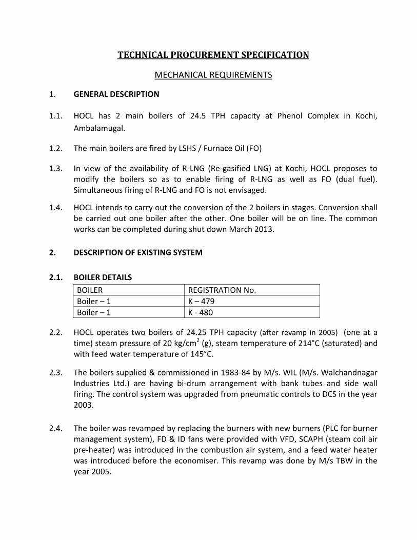

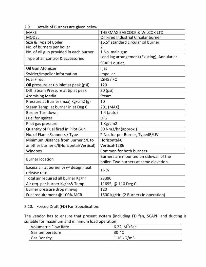
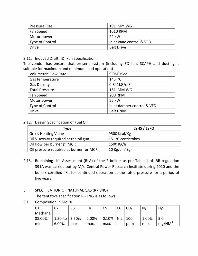


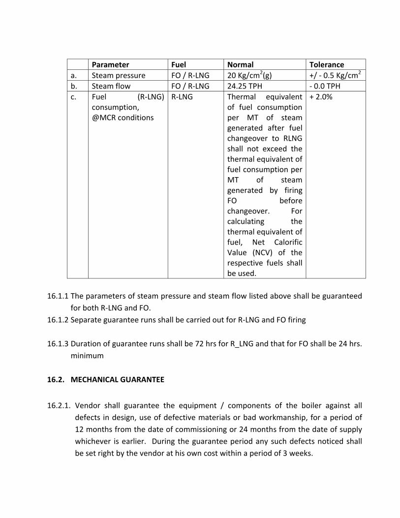
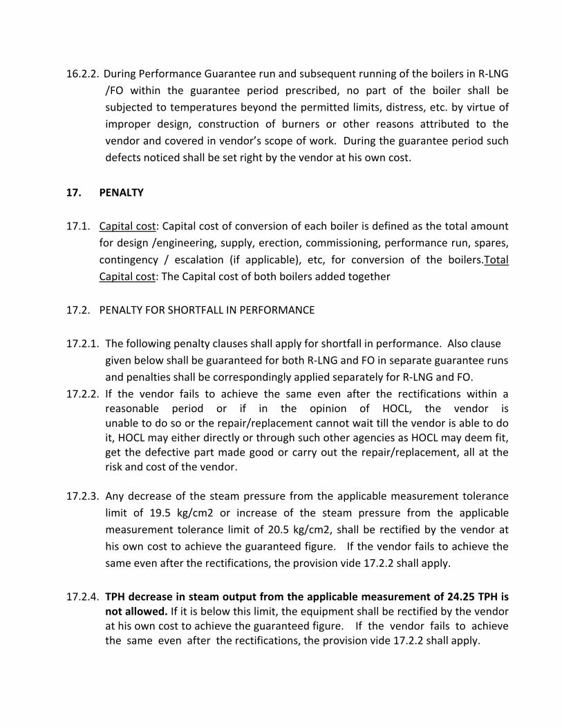
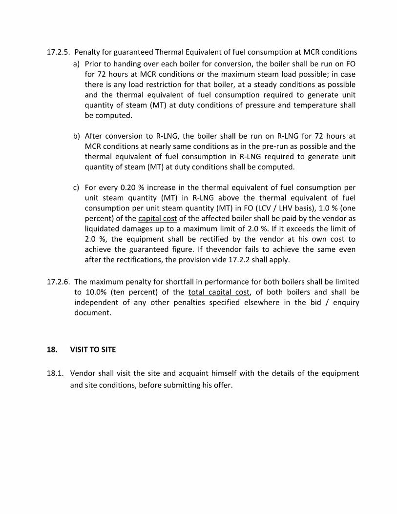


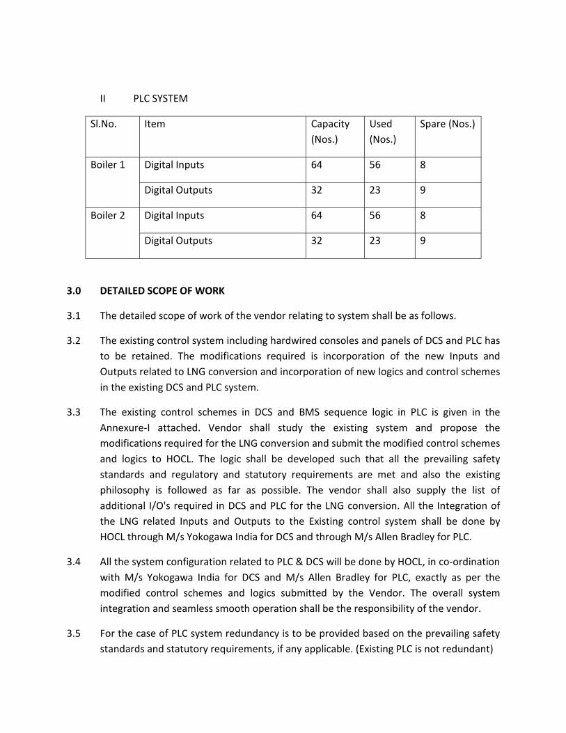


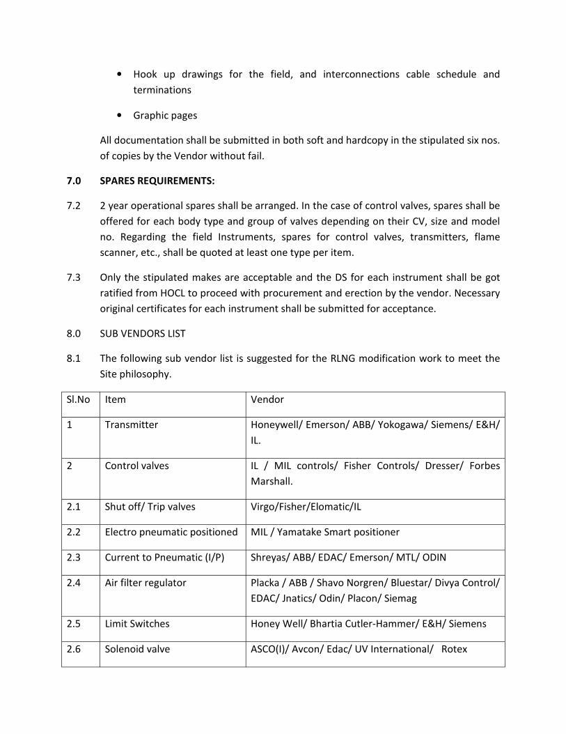

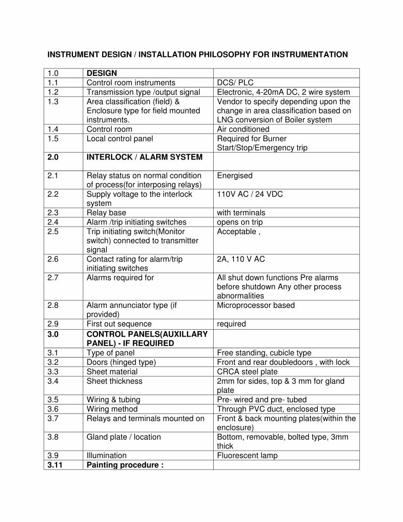


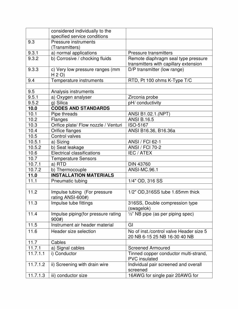
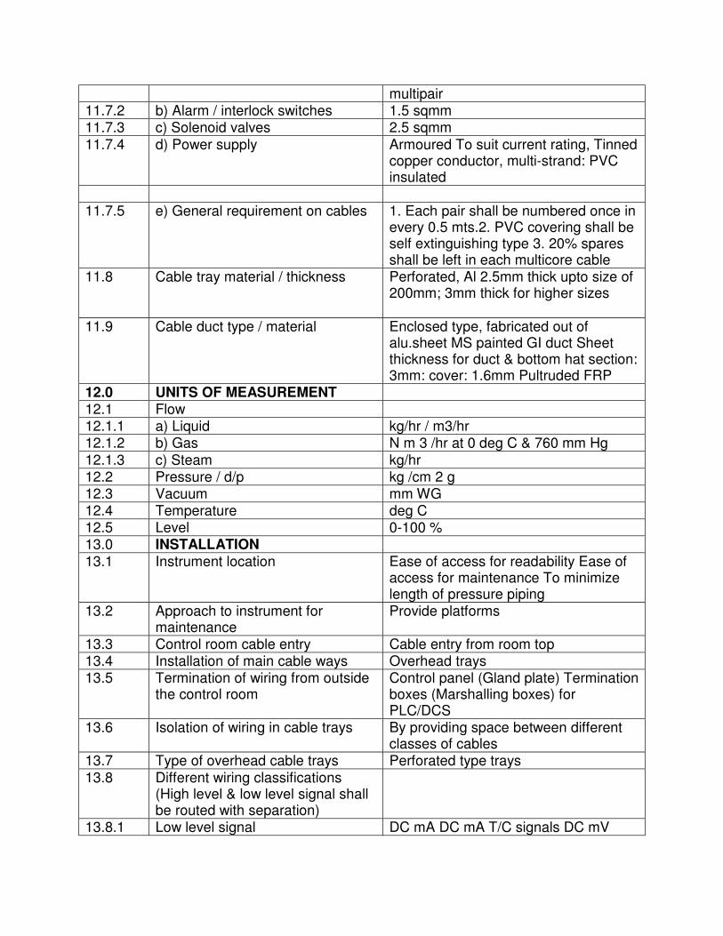


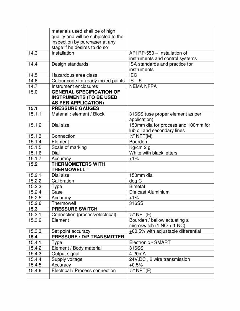


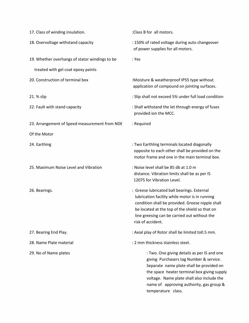


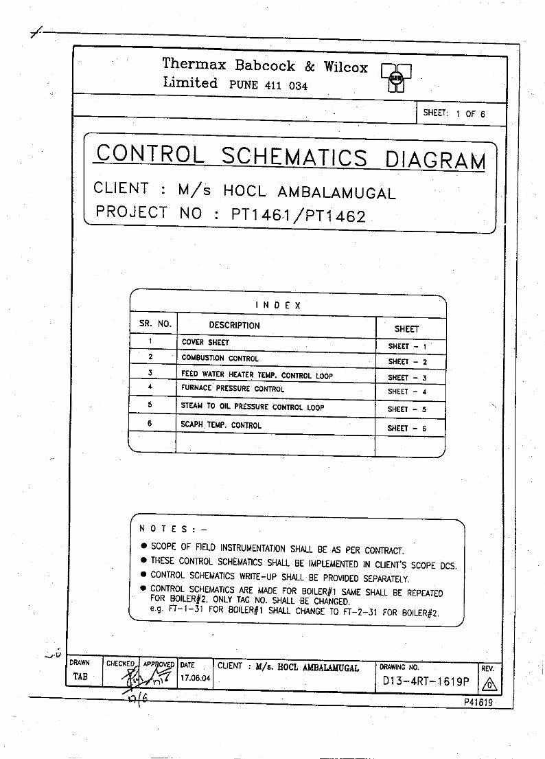


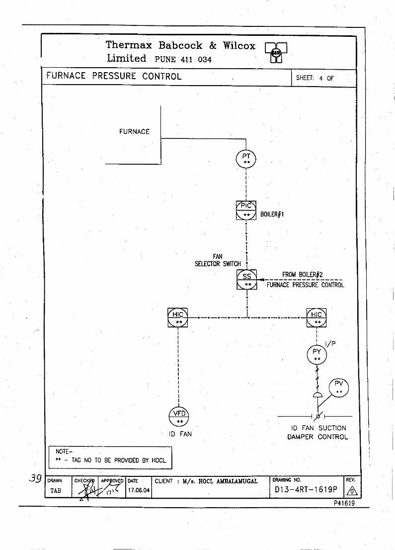
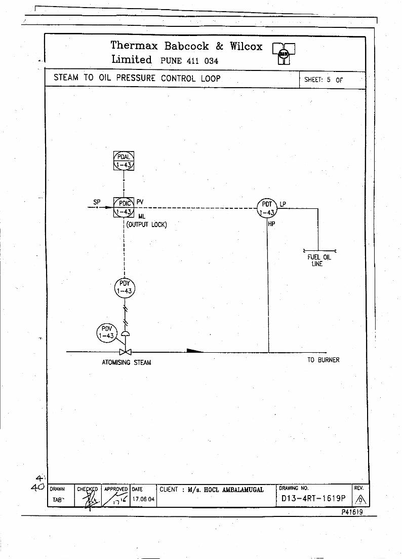


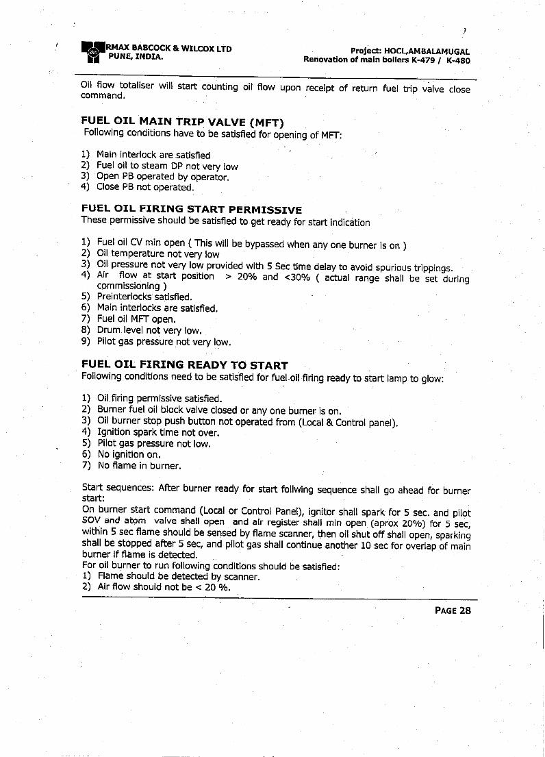
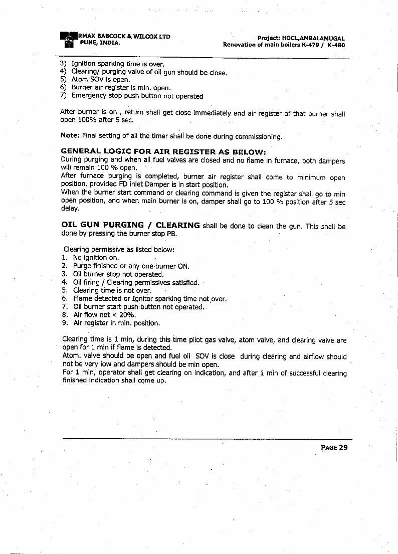


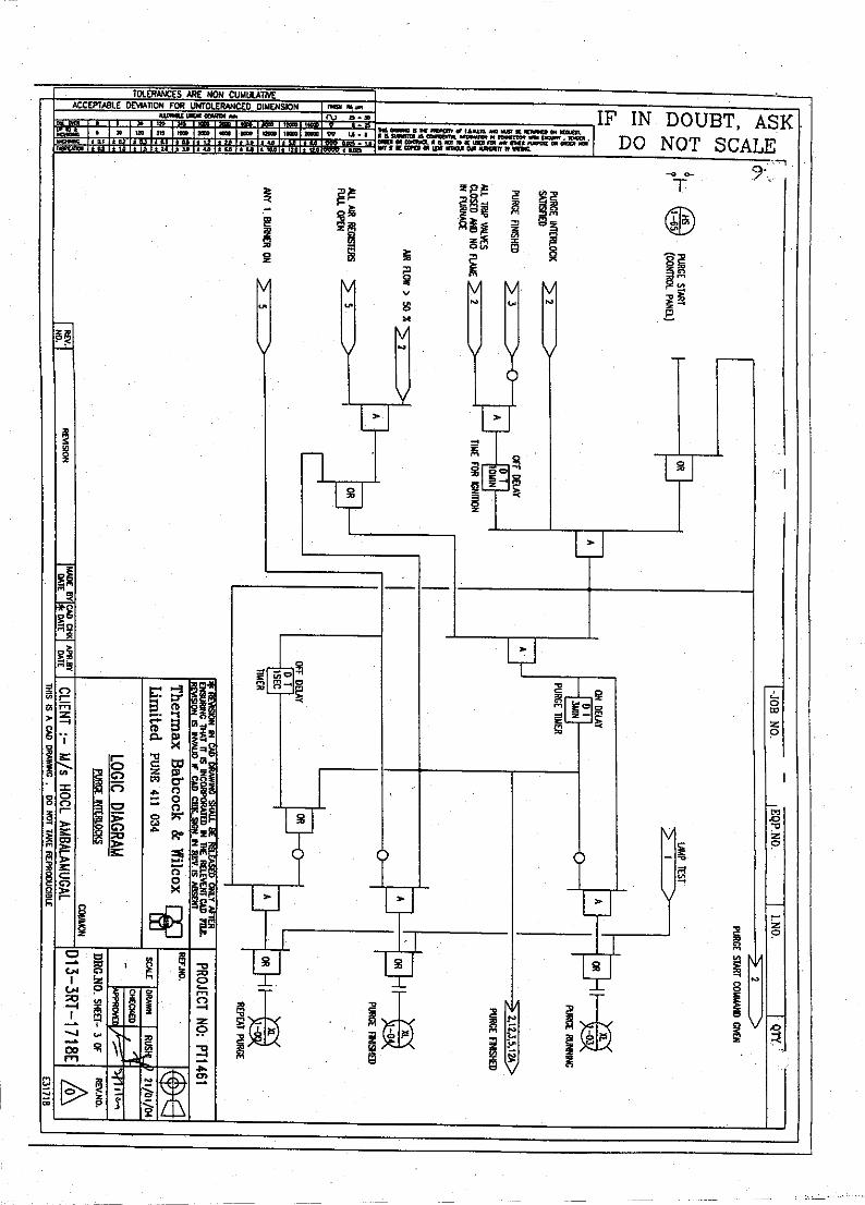
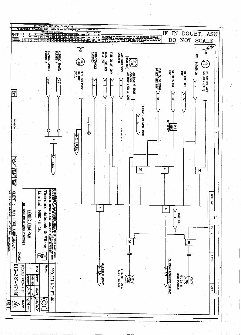
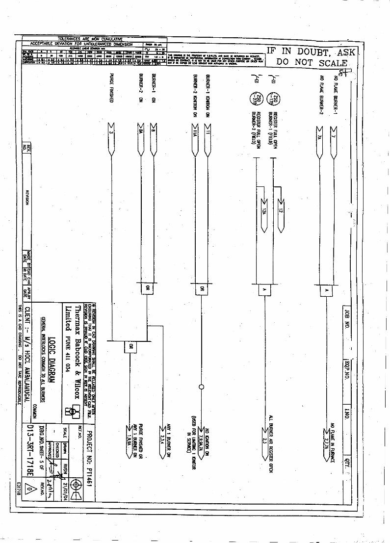


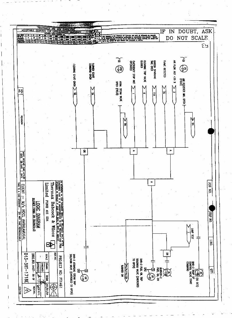

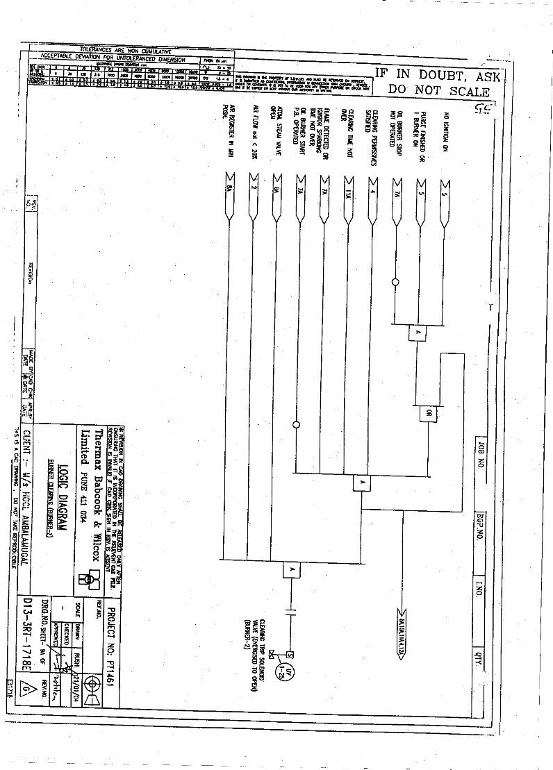


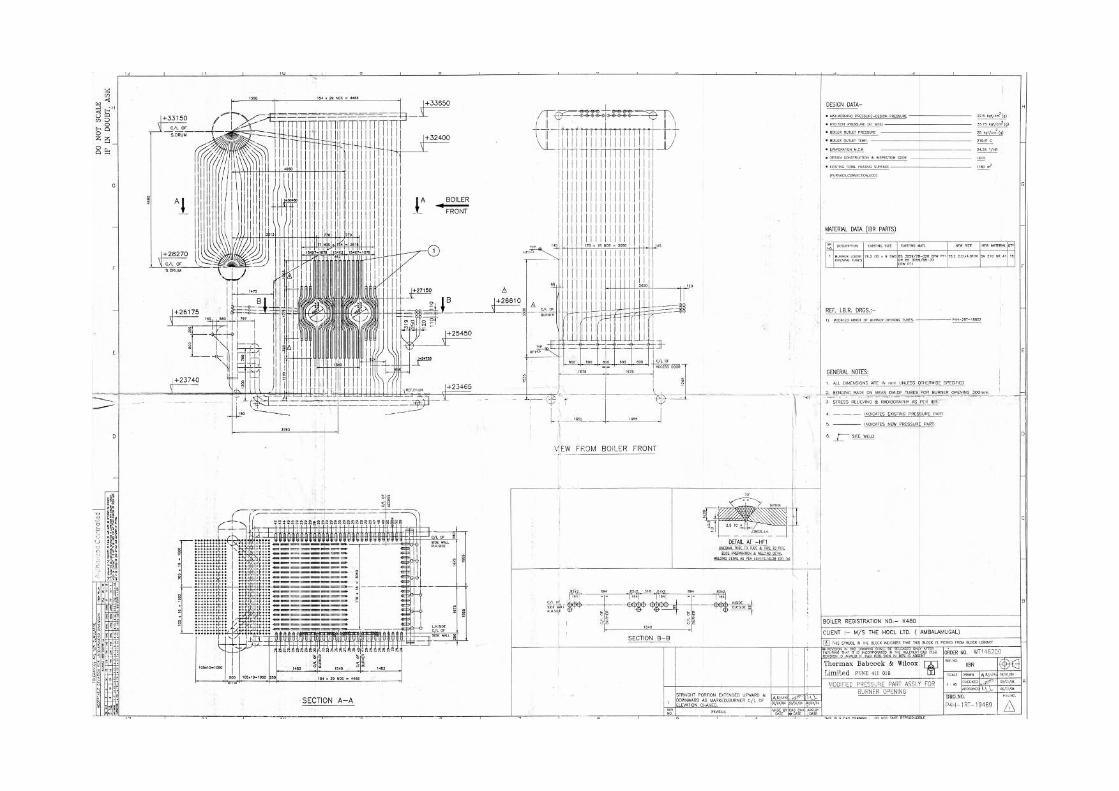


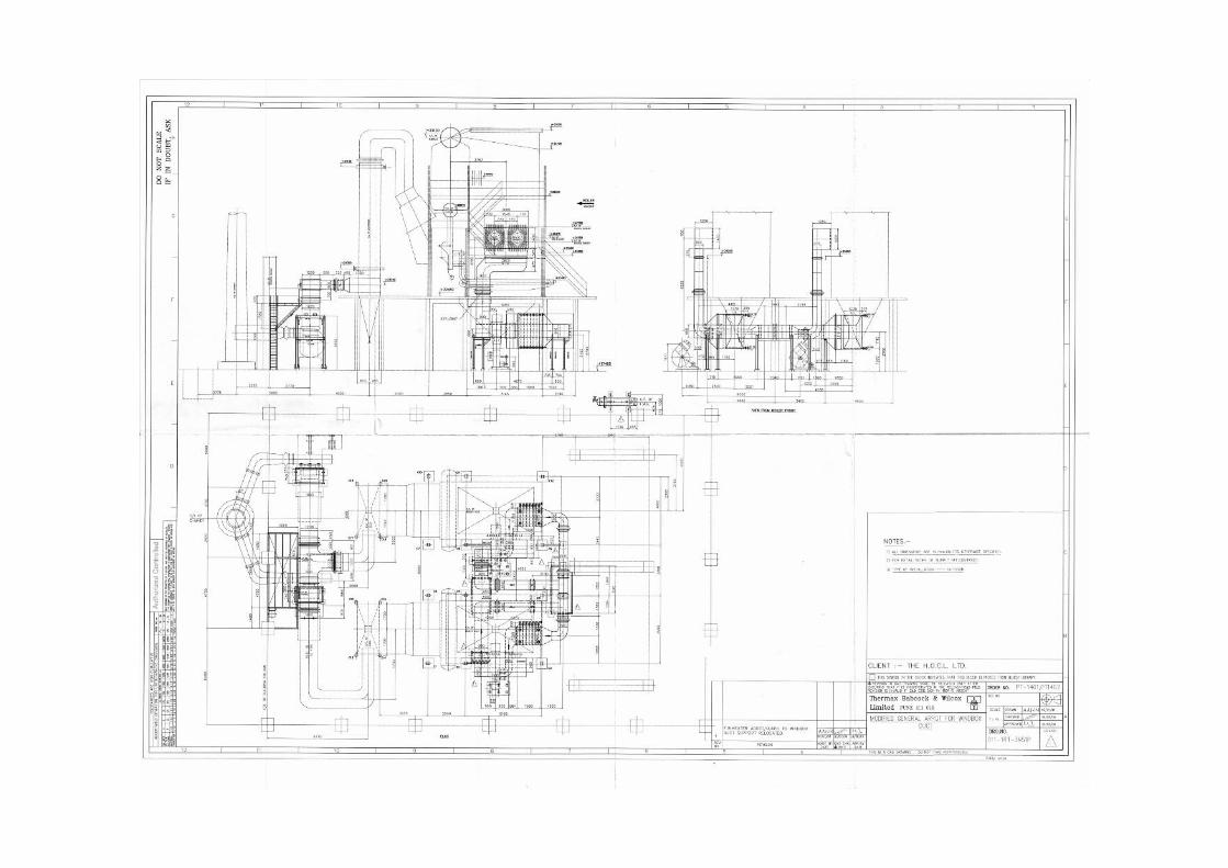


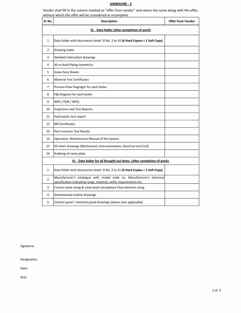
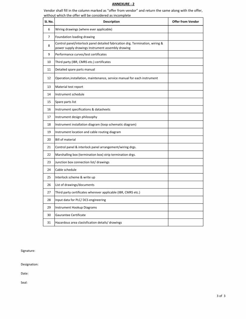
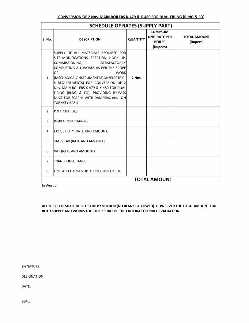
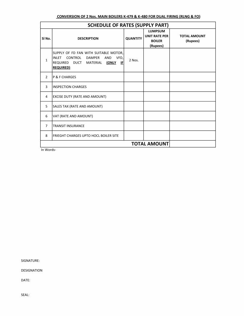
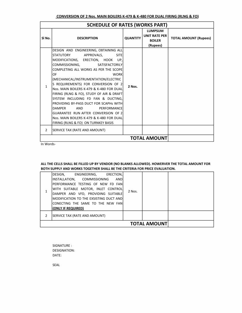
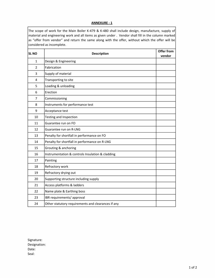


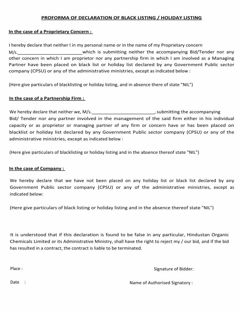
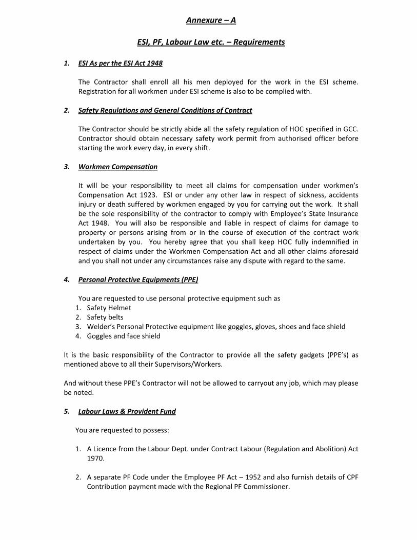


![HINDUSTAN ORANIC CHEMICALS LIMITED · HINDUSTAN ORANIC CHEMICALS LIMITED 1 Annual Report 2014-15 BOARD OF DIRECTORS [as on 11-08-2015] SHRI V.B. RAMACHANDRAN NAIR Chairman & Managing](https://static.documents.pub/doc/80x56/5f26065a851c985d9d6933df/hindustan-oranic-chemicals-hindustan-oranic-chemicals-limited-1-annual-report-2014-15.jpg)