18
HL 1610 S HL 1810 S HL 1910 E HL 2010 E HG 2310 LCD HG 2510 ESD i

HL 1610 S HL 1810 S HL 1910 E HL 2010 EHG 2310 LCDHG 2510 ESD
i
HL1610S_USA 20.05.2005 15:40 Uhr Seite 2

- 2 -
English
IMPORTANT SAFETY INSTRUCTIONSREAD THESE INSTRUCTIONS
UL WARNING: Read this instruction book before using. To reduce risk of fire or electricshock, do not expose to rain or moisture. Store indoors. Double insulated. When servicing,use only identical replacement parts. When using electric tools, basic safety precautionsshould always be followed to reduce risk of fire, electric shock and personal injury. This hotair gun operates at 1200°F with no visual indication of temperature (no flame). Never leavedevice unattended. Otherwise risk of fire. The heat stream at the outlet nozzle will burn flesh.Do not turn on heat gun with hand in front of nozzle. DO NOT USE NEAR COMBUSTIBLE LIQ-UIDS. DO NOT USE FOR: � Heating gas engines � Heating car batteries � Thawing refrigerator equipment.
WARNING!This tool is capable of producing temperatures up to 1200° F of flameless heat at the nozzle. ALWAYS:� Direct the heat away from yourself and others.� Prevent ignition of combustible materials on or near the workpiece.� Prevent blockage of intake and nozzle openings.� Keep a fully charged fire extinguisher on hand.� Allow the nozzle and accessory tips to cool to room temperature before storage.
WARNING: Some dust created by power sanding, sawing, grinding, drilling and otherconstruction activities contains chemicals known (to the State of California) to cause cancer,birth defects, or other reproductive harm. Some examples of these chemicals are:� lead from lead-based paints,� crystalline silica from bricks and cement and other masonry products, and� arsenic and chromium from chemically-treated lumber.Your risk from these exposures varies, depending on how often you do this type of work.To reduce your exposure to these chemicals: work in a well ventilated area, and work withapproved safety equipment, such as those dust masks that are specially designed to filter outmicroscopic particles.
Cautions1. WARNING: Hidden areas such as behind walls, ceilings, floors, soffit boards and other
panels may contain flammable materials that could be ignited by the heat gun when working in these locations. The ignition of these materials may not be readily apparent andcould result in property damage and injury to persons. Do not use if in doubt about thishazard. When working in these locations, keep the heat gun moving in a back-and-forthmotion. Lingering or pausing in one spot could ignite the panel or the material behind it.
2. This heat gun can produce up to 1200° F of flameless heat at the nozzle. Do not directairstream at clothing, hair or other body parts. Do not use as a hair dryer.
3. Do not use near flammable liquids or in an explosive environment (fumes, gases or dust).Remove materials or debris, that may become ignited, from work area.
4. Always hold tool by plastic enclosure. The metal nozzle requires approximately 20 minutesto cool to where it can be touched. Do not touch nozzle or accessory tips until cool.
5. Do not store tool until nozzle has cooled to room temperature. Place tool in a clear areaaway from combustible materials while cooling.
6. Do not cut off airflow by placing nozzle too close to workpiece. Keep intake vents cleanand clear of obstructions.
7. Place tool on a level surface with the support rubber ring when tool is not hand held. Place cord in a position that won’t cause tipping.
8. Do not leave tool unattended while running or cooling down. Otherwise risk of fire.9. Keep a fully charged fire extinguisher nearby.
10. Do not direct airflow directly on glass.11. Shield materials around the heated area to prevent damage or fire.12. Use only with 120 V AC voltage.13. Do not use in wet conditions.14. Not to be used by children. This is not a toy and should be respected.15. Do not use in bath or over water.16. Safety glasses should be worn when using this tool.17. It is recommended that leather gloves be worn when using a heat gun.
HL1610S_USA 20.05.2005 15:40 Uhr Seite 3

- 3 -
English
18. Always unplug after use.19. WARNING: Extreme care should be taken when stripping paint. The peelings, residue and
vapors of paint may contain lead, which is poisonous. Any pre-1977 paint may contain leadand paint applied to homes prior to 1950 is likely to contain lead. Once deposited on sur-faces, hand to mouth contact can result in the ingestion of lead. Exposure to even low levels of lead can cause irreversible brain and nervous system damage; young and unbornchildren are particularly vulnerable. Before beginning any paint removal process you shoulddetermine whether the paint you are removing contains lead. This can be done by yourlocal health department or by a professional who uses a paint analyzer to check the leadcontact of the paint to be removed. LEAD-BASED PAINT SHOULD ONLY BE REMOVED BYA PROFESSIONAL AND SHOULD NOT BE REMOVED USING A HEAT GUN.
Persons removing materials should follow these guidelines.
1. Move the work piece outdoors. If this is not possible, keep the work area well ventilated.Open the windows and put an exhaust fan in one of them. Be sure the fan is moving the airfrom inside to outside.
2. Remove or cover any carpets, rugs, furniture, clothing, cooking utensils and air ducts.3. Place drop cloths in the work area to catch any residue. Wear protective clothing such as
extra work shirts, overalls and hats.4. Work in one room at a time. Furnishings should be removed or placed in the center of the
room and covered. Work areas should be sealed off from the rest of the dwelling by sealingdoorways with drop cloths.
5. Children, pregnant or potentially pregnant women and nursing mothers should not be presentin the work area until the work is done and all clean up is complete.
6. Wear a dust respirator mask or a dual filter (dust and fume) respirator mask which has beenapproved by the Occupational Safety and Health Administration (OSHA), the National Instituteof Safety and Health (NIOSH), or the United States Bureau of Mines. These masks andreplaceable filters are readily available at major hardware stores. Be sure the mask fits.Beards and facial hair may keep masks from sealing properly. Change filters often. DISPOSABLE PAPER MASKS ARE NOT ADEQUATE.
7. Use caution when operating the heat gun. Keep the heat gun moving as excessive heat willgenerate fumes which can be inhaled by the operator.
8. Keep food and drink out of the work area. Wash hands, arms and face and rinse mouthbefore eating or drinking. Do not smoke or chew gum or tobacco in the work area.
9. Clean up all removed residue and dust by wet mopping the floors. Use a wet cloth to cleanall walls, sills and any other surface where residue or dust is clinging. DO NOT SWEEP, DRYDUST OR VACUUM. Use a high phosphate detergent or trisodium phosphate (TSP) to washand mop areas.
10. At the end of each work session put the residue and debris in a double plastic bag, close itwith tape or twist ties, and dispose of properly.
11. Remove protective clothing and work shoes in the work area to avoid carrying dust into therest of the dwelling. Wash work clothes separately. Wipe shoes off with a wet rag that is thenwashed with the work clothes. Wash hair and body thoroughly with soap and water.
SAVE THESE INSTRUCTIONS
HL1610S_USA 20.05.2005 15:40 Uhr Seite 4

- 4 -
English
Double Insulated ToolsTools marked with the words “Double Insulated” are equipped with a two prong plug.These tools have a special insulation system that complies with applicable UL standards
. They do not require grounding. ”Double Insulated” tools, like this one, havetwo prong cords and can use either a two or three prong extension cord.
“This appliance has a polarized plug (one blade is wider than the other). To reducethe risk of electric shock, this plug is intended to fit in a polarized outlet only oneway. If the plug does not fit fully in the outlet, reverse the plug. If it still does not fit,contact a qualified electrician. Do not modify the plug in any way.”
Extension CordsAs the distance from the supply outletincreases, heavier gauge extension cords are required. The use of extension cords ofinadequate size wire causes a serious dropin voltage and loss of power. Protect the cordfrom damage. Keep cords away from exces-sive heat, sharp edges and damp or wetareas. Repair or replace damaged extensioncords before using.
Ext. Cord Length Wire Size
040 Ft. 16085 Ft. 14100 Ft. 12170 Ft. 10270 Ft. 08400 Ft. 06650 Ft. 04
Note: The HG 2510 ESD is not ”Double Insulated”. It utilizes a 3-prong groundedplug and, for safety, must only be used with a 3-prong extension cord.
HL1610S_USA 20.05.2005 15:40 Uhr Seite 5

Voltage
Output
Switch stage
Airflow (cf/min.)
Temperature
Controls
Programs
120 V, 60 Hz
1300 W
1 2
8.5 14.8
575 ° 950 °F
–
–
- 5 -
English
HL 1610 SHL 1810 SHL 1910 EHL 2010 EHG 2310 LCDHG 2510 ESD
Technical specifications
for deciding to choose a STEINELheat gun. This tool can be usedfor completing a wide range ofjobs safely and reliably, such assoldering, welding PVC, shaping,
drying, shrink-fitting, stripping paintetc. All STEINEL tools are manu-factured to the highest standardsand undergo a strict process ofquality control.
Used in the proper manner, thisheat gun will give you lasting satisfaction.
°C = °F
100 212
200 392
300 572
400 752
500 932
600 1112
700 1292
Thank you
Subject to technical modifications
Conversion °C to °F
°F = °C
100 38
200 93
300 149
400 204
500 260
600 316
700 371
800 427
900 482
1000 538
1100 593
1200 649
Conversion °F to °C
120 V, 60 Hz
1600 W
1 2
3.6 3.6 – 17.6
120 ° 120 – 1200 °F
pushbutton air/temperature controlin 10 °F increments, with LCD display
4 preset programs,with ”LOC”LockableOverride Control™
120 V, 60 Hz
1600 W
1 2
3.6 3.6 – 17.6
120 ° 120 – 1200 °F
pushbutton air/temperature controlin 10 °F increments, with LCD display
4 preset programs,with ”LOC” LockableOverride Control™
120 V, 60 Hz
1500 W
1 2 3
3.6 10.6 17.6
120 ° 120 – 1150 °F
pushbutton temperature control in10 °F increments, with LCD display
–
120 V, 60 Hz
1500 W
1 2 3
3.6 10.6 17.6
120 ° 120 – 1100 °F
temperature dial
–
120 V, 60 Hz
1400 W
1 2 3
3.6 10.0 15.9
120 ° 750° 1100 °F
–
–
HL1610S_USA 20.05.2005 15:40 Uhr Seite 6
- 6 -
English
Features - Getting started
HL 1610 S
The tool is switched ON and OFF at the two-stage switch on the back of the grip handle. Airflow and tem-perature can be adjusted to 2 settings. Stage 1 reaches 575 °F at an air flow of 8.5 cf/min, stage 2 reaches 950 °F at 14.8 cf/min.
HL 2010 E
The tool is switched ON and OFF at the three-stage switch on the back of the grip handle. In addition to three-stage speed/airflow control, temperature can be continuously adjusted over a range of 120 °–1150 °F by thepushbuttons. The target temperature can be increased in 10 °F steps by pressing the ”+” side of the tempera-ture pushbutton or reduced by pressing the ”–” side of the temperature pushbutton. Pressing the button brieflyincreases or reduces the target temperature by one 10 °F step. Keeping the button pressed will continue toincrease or reduce the temperature in steps of 10 °F until the button is released or the minimum or maximumtemperature is set.
Blower stage 1 delivers a temperature of 120 °F. The tool will take a short while to cool to 120 °F after switchingdown to blower stage 1 when it has been operating at high temperatures on blower stage 2 or 3. While thetool is cooling down, the LCD display shows the actual temperature at the nozzle outlet. After switching OFF,the tool stays in the last setting. The outlet protection tube can be removed in order to install the overheadsecurity hanger.
HL 1810 S
The tool is switched ON and OFF at the three-stage switch on the back of the grip handle. Airflow and temperature can be adjusted to 3 settings. Stage 1 is a Cool air stage at 120 °F with an airflow rate of 3.6 cf/min. Stage 2 reaches 750 °F at an airflow of 10.0 cf/min., stage 3 delivers 1100 °F at 15.9 cf/min. The outlet protection tube can be removed in order to install the overhead security hanger.
HL 1910 E
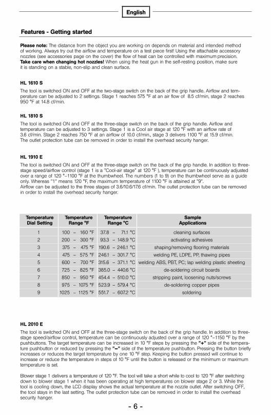
The tool is switched ON and OFF at the three-stage switch on the back of the grip handle. In addition to three-stage speed/airflow control (stage 1 is a ”Cool-air stage” at 120 °F ), temperature can be continuously adjustedover a range of 120 °–1100 °F at the thumbwheel. The numbers (1 to 9) on the thumbwheel serve as a guideonly. Whereas ”1” means 120 °F, the maximum temperature of 1100 °F is attained at ”9”. Airflow can be adjusted to the three stages of 3.6/10.6/17.6 cf/min. The outlet protection tube can be removedin order to install the overhead security hanger.
Please note: The distance from the object you are working on depends on material and intended method of working. Always try out the airflow and temperature on a test piece first! Using the attachable accessory nozzles (see accessories page on the cover) the flow of heat can be controlled with maximum precision. Take care when changing hot nozzles! When using the heat gun in the self-resting position, make sure it is standing on a stable, non-slip and clean surface.
TemperatureDial Setting
1
2
3
4
5
6
7
8
9
Temperature Range °F
100 – 160 °F
200 – 300 °F
375 – 475 °F
475 – 575 °F
600 – 700 °F
725 – 825 °F
850 – 950 °F
975 – 1075 °F
1025 – 1125 °F
Temperature Range °C
37.8 – 71.1 °C
93.3 – 148.9 °C
190.6 – 246.1 °C
246.1 – 301.7 °C
315.6 – 371.1 °C
385.0 – 440.6 °C
454.4 – 510.0 °C
523.9 – 579.4 °C
551.7 – 607.2 °C
Sample Applications
cleaning surfaces
activating adhesives
shaping/removing flooring materials
welding PE, LDPE, PP, thawing pipes
welding ABS, PBT, PC; lap welding plastic sheeting
de-soldering circuit boards
stripping paint, loosening nuts/screws
de-soldering copper pipes
soldering
HL1610S_USA 20.05.2005 15:40 Uhr Seite 7
- 7 -
English
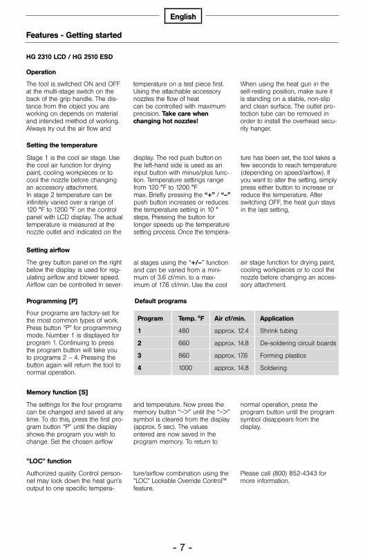
Four programs are factory-set forthe most common types of work.Press button “P” for programmingmode. Number 1 is displayed forprogram 1. Continuing to pressthe program button will take youto programs 2 – 4. Pressing thebutton again will return the tool tonormal operation.
Features - Getting started
The tool is switched ON and OFFat the multi-stage switch on theback of the grip handle. The dis-tance from the object you areworking on depends on materialand intended method of working.Always try out the air flow and
temperature on a test piece first.Using the attachable accessorynozzles the flow of heat can be controlled with maximumprecision. Take care whenchanging hot nozzles!
When using the heat gun in theself-resting position, make sure itis standing on a stable, non-slipand clean surface. The outlet pro-tection tube can be removed inorder to install the overhead secu-rity hanger.
Default programs
The settings for the four programscan be changed and saved at anytime. To do this, press the first pro-gram button “P” until the displayshows the program you wish tochange. Set the chosen airflow
and temperature. Now press thememory button “–>” until the “–>”symbol is cleared from the display(approx. 5 sec). The valuesentered are now saved in the program memory. To return to
normal operation, press theprogram button until the programsymbol disappears from the display.
Operation
HG 2310 LCD / HG 2510 ESD
Stage 1 is the cool air stage. Usethe cool air function for dryingpaint, cooling workpieces or tocool the nozzle before changingan accessory attachment.In stage 2 temperature can beinfinitely varied over a range of120 °F to 1200 °F on the controlpanel with LCD display. The actualtemperature is measured at thenozzle outlet and indicated on the
display. The red push button onthe left-hand side is used as aninput button with minus/plus func-tion. Temperature settings rangefrom 120 °F to 1200 °F max. Briefly pressing the “+” / “–”push button increases or reducesthe temperature setting in 10 °steps. Pressing the button forlonger speeds up the temperaturesetting process. Once the tempera-
ture has been set, the tool takes afew seconds to reach temperature(depending on speed/airflow). Ifyou want to alter the setting, simplypress either button to increase orreduce the temperature. Afterswitching OFF, the heat gun staysin the last setting.
Setting the temperature
The grey button panel on the rightbelow the display is used for reg-ulating airflow and blower speed.Airflow can be controlled in sever-
al stages using the “+/–” functionand can be varied from a mini-mum of 3.6 cf/min. to a max-imum of 17.6 cf/min. Use the cool
air stage function for drying paint,cooling workpieces or to cool the nozzle before changing an acces-sory attachment.
Setting airflow
Programming [P]
Memory function [S]
Authorized quality Control person-nel may lock down the heat gun’soutput to one specific tempera-
ture/airflow combination using the”LOC” Lockable Override Control™feature.
Please call (800) 852-4343 formore information.
”LOC” function
Program Temp. °F Air cf/min. Application
1 480 approx. 12.4 Shrink tubing
2 660 approx. 14.8 De-soldering circuit boards
3 860 approx. 17.6 Forming plastics
4 1000 approx. 14.8 Soldering
HL1610S_USA 20.05.2005 15:40 Uhr Seite 8

- 8 -
English
Applications
F Soft soldering: First, cleanmetal parts you want to join. Then,heat the point you want to solderand offer up the soldering wire.Use flux or a soldering wire with aflux core to prevent oxide forming.
G Welding and joining plastic:All parts being welded must be ofthe same plastic material. Use anappropriate welding rod.
Here are some of the applicationsyou can use STEINEL heat gunsfor. This selection is by no meansexhaustive – no doubt you canimmediately think of other exam-ples.
A Stripping paint: Paint is soft-ened and can be removed with astripping knife and paint scraperto leave a clean surface.
B Shrinking tubing on cables:The shrink tubing is slipped overthe section you want to insulateand heated. The tubing shrinks by approx. 50% in diameter togive a sealed union. Shrinking is particularly fast and even usingreflector nozzles. Sealing and stabilizing cable breaks, insulatingsoldered joints, gathering cableruns, sheathing terminal blocks.
C Forming PVC: Sheeting, pip-ing or ski boots can be softenedand formed with heat.
D Lighting the barbecue:Gets charcoal glowing in next tono time; no more waiting.
E Thawing: Water pipes, frozendoor locks, steps. Gently thawsand dries all in one go.
H De-soldering: Circuit boardsand other electronic componentsmay be soldered or de-solderedusing a reduction tip fitted on anelectronic heat gun.
I Joining sheeting: The sheetsare overlapped and weldedtogether. A slit nozzle is used todirect heat under the overlap,then the two sheets are firmlypressed together with a feedroller. Also possible: RepairingPVC tarpaulins by overlap weld-ing with a slit nozzle.
Rigid PVC
PlasticisedPVC
Soft PE(LDPE)Polyethylene
Hard PE(HDPE)Polyethylene
PPPolypropylene
ABS
Pipes, fittings, sheets, building pro-files, technical mouldingsWelding temperature 580 °FFloor coverings, wallpapers,hoses, sheets, toysWelding temperature 760 °FDomestic and electrotechnicalarticles, toysWelding temperature 480 °FBaths, baskets, canisters, insulat-ing material, pipesWelding temperature 580 °FHT drainage pipes, mouldedseats, packaging, car componentsWelding temperature 480 °FCar components, equipmenthousings, casesWelding temperature 660 °F
Carbonizes in the flame, pungent odour;crashing sound
Smoking, yellowish-green flame, pungent odour; silent
Light yellow flame, drips continue to burn, smells of a candle being extinguished; dull soundLight yellow flame, drips continue to burn, smells of a candle being extinguished; crashing soundbright flame with a blue core, drips continue to burn, pungent odour;crashing soundblack, fluffy smoke, sweet odour; crashing sound
Material Application types Distinguishing characteristics
J Accessories
Your dealer has a wide range of accessories for you to choose from. (* for HL 1910 E, HL 2010 E, HG 2310 LCDand HG 2510 ESD only)
1 Spreader nozzle, 75 mmProd. No. 07011
2 Spreader nozzle, 50 mmProd. No. 07021
3 Butt welding disc, 80 mm*Prod. No. 07211
4 Lap welding slit tipProd. No. 07471
5 Welding rod tipProd. No. 07091
6 Lap welding slit tipProd. No. 07101
7 Rod welding slit tipProd. No. 07201
8 Deflector nozzle, 75 mmProd. No. 07031
9 Deflector nozzle, 50 mmProd. No. 07041
10 Seam roller, 45 mmProd. No. 01250
11 Plastic welding rodsProd. No.
Rigid PVC 07311LDPE 07331HDPE 07121PP 07341ABS 07421
12 Overhead SecurityHanger Prod. No. 01481
13 Reflector nozzle, 75 mmProd. No. 07301
14 Reflector nozzle, 39 mmProd. No. 07051
15 Reflector nozzle, 14 mm*Prod. No. 07461
16 Reflector nozzle, 9 mmProd. No. 07061
17 Reducer nozzle, 9 mm*Prod. No. 07062
18 Reducer nozzle, 14 mm*Prod. No. 07071
19 Reducer nozzle, 20 mm*Prod. No. 07081
20Angle slit nozzleProd. No. 07511
21 Wire protection tubeProd. No. 07402
HL1610S_USA 20.05.2005 15:40 Uhr Seite 9

- 9 -
English
IG
A B C
D E F
H
920 - 1100 °F 480 - 580 °F 480 - 920 °F
920 - 1100 °F 480 - 580 °F 1100 °F
HL 1610 S / HL 1810 S / HL 1910 E / HL 2010 E / HG 2310 LCD / HG 2510 ESD
J
HL 1910 E / HL 2010 E / HG 2310 LCD / HG 2510 ESD
Accessories
�
480 - 760 °F 650 - 750 °F 580 - 760 °F
� � � �� �
� �
� � � � �
21�
��
�
HL1610S_USA 20.05.2005 15:40 Uhr Seite 10
- 10 -
English
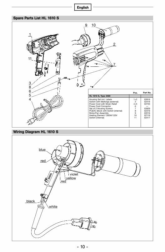
Tool elements / spare parts list HG 2310 LCDSpare Parts List HL 1610 S
1
11
9 10
2
7
38654
Part No.Pos.
HL 1610 S, Type 3480
Housing Set incl. LabelsSwitch with Markings (external)Power Cord with Strain ReliefPower Cord ConnectorSet of 5 Housing ScrewsPCB/IC Block with Switch (internal)Motor/Fan AssemblyHeating Element 1300W/120VSwitch (internal)
0281602416 02723
—02829 02316022160211602417
1+23
4+5 6789
1011
blue
red
violetyellow
red
white
black
Wiring Diagram HL 1610 S
HL1610S_USA 20.05.2005 15:40 Uhr Seite 11
1 5 13 14
412
78
109
2
11
6
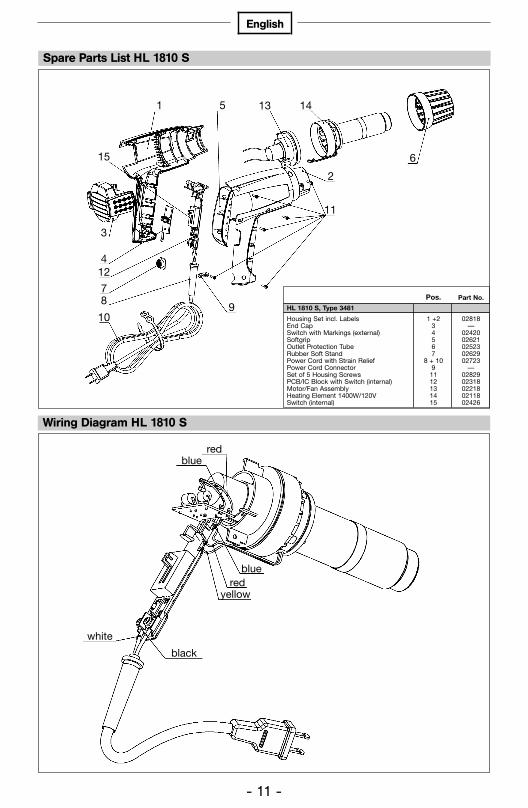
Spare Parts List HL 1810 S
Part No.Pos.
02818 —
02420 02621 02523 02629 02723
—02829 02318022180211802426
1 +234567
8 + 1091112131415
HL 1810 S, Type 3481
Housing Set incl. LabelsEnd CapSwitch with Markings (external)SoftgripOutlet Protection TubeRubber Soft StandPower Cord with Strain ReliefPower Cord ConnectorSet of 5 Housing ScrewsPCB/IC Block with Switch (internal)Motor/Fan AssemblyHeating Element 1400W/120VSwitch (internal)
- 11 -
English
blue
blue
red
yellowred
Wiring Diagram HL 1810 S
3
15
white
black
HL1610S_USA 20.05.2005 15:40 Uhr Seite 12

- 12 -
English
1 4 12 13
7
2
10
9
11
6
8
5
Spare Parts List HL 1910 E
Part No.Pos.
HL 1910 E, Type 3484
Housing Set incl. LabelsSwitch with Markings (external)SoftgripRubber Soft StandPower Cord with Strain ReliefOutlet Protection TubePower Cord ConnectorSet of 5 Housing ScrewsPCB/IC Block with Switch and End CapMotor/Fan AssemblyHeating Element 1500W/120VSwitch (internal)
1 + 2345
6 + 879
1011121314
02819 02420 02621 02629 02723 02523
—02829 02319 02225 0212002426
whiteblack
2:1
green
red
red blue
blue
yellow
yellow (fuse)
Wiring Diagram HL 1910 E
314
HL1610S_USA 20.05.2005 15:40 Uhr Seite 13
- 13 -
English
1 4 12 13
3
8
65
9
2
10
7
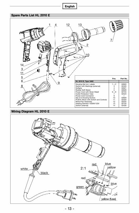
Spare Parts List HL 2010 E
Part No.Pos.
02820 02420 02621 02629 02723 02523
—02829 02320022250212002426
1 + 2345
6 + 879
10 11121314
HL 2010 E, Type 3482
Housing Set incl. LabelsSwitch with Markings (external)SoftgripRubber Soft StandPower Cord with Strain ReliefOutlet Protection TubePower Cord ConnectorSet of 5 Housing ScrewsPCB/IC Block with Switch and ControlsMotor/Fan AssemblyHeating Element 1500W/120VSwitch (internal)
whiteblack
2:1
green
red
red blue
blue
yellow
yellow (fuse)
Wiring Diagram HL 2010 E
11
14
HL1610S_USA 20.05.2005 15:40 Uhr Seite 14

- 14 -
English
whiteblack
2:1
green
red
red blue
blue
yellow
yellow (fuse)
Wiring Diagram HG 2310 LCD
7
131 4 12
2
10
9
3
6
8
115 Part No.Pos.
02823 02423 026210262902723 02523
—02829 02323022250212302426
1 + 2345
6 + 8791011121314
HG 2310 LCD, Type 3483
Housing Set incl. LabelsSwitch with Markings (external)SoftgripRubber Soft StandPower Cord with Strain ReliefOutlet Protection TubePower Cord ConnectorSet of 5 Housing ScrewsPCB/IC Block with Switch and ControlsMotor/Fan AssemblyHeating Element 1600W/120VSwitch (internal)
Spare Parts List HG 2310 LCD
14
HL1610S_USA 20.05.2005 15:40 Uhr Seite 15

whiteblack
2:1
green
green
red
red blue
blue
yellow
yellow (fuse)
- 15 -
English
Wiring Diagram HG 2510 ESD
7
Spare Parts List HG 2510 ESD
Part No.Pos.
02825 02425 02621 02629 02725 02525
—02829 02325022250212502426
1 + 2345
6 + 879
1011121314
HG 2510 ESD, Type 3488
Housing Set incl. Labels (ESD)Switch with Markings (external)SoftgripRubber Soft StandPower Cord with Strain Relief (ESD)Outlet Protection Tube (ESD)Power Cord ConnectorSet of 5 Housing ScrewsPCB/IC Block with Switch and Controls (ESD)Motor/Fan AssemblyHeating Element 1600W/120V (ESD)Switch (internal)
143
1156
89
10
2
131241
HL1610S_USA 20.05.2005 15:40 Uhr Seite 16

- 16 -
English
Limited WarrantySTEINEL warranties its heat guns and glue guns, if properly operated and main-tained, and used under normal conditions, for a period of one (1) year from thedate of purchase. For heat guns, this warranty includes the heating element.Specifically EXCLUDED from warranty are tools that have been subject to abuse,tools that have been opened or repaired by anyone other than STEINEL, toolsthat have been modified in any way or mounted onto machinery/equipment, andtools that have been put into continuous operation. These are hand held powertools and are intended for use as such. Any other use voids STEINEL’s warranty.
Warranty and Repair ProceduresIn the event of product failure, please call STEINEL customer service directlyat (800) 852-4343. We will attempt to troubleshoot the difficulty via phone. If warranty work or other repair appears necessary, we will issue an RGA#and ask that the tool be returned to us at the below address (postage paid by the customer), with the RGA# clearly marked, and accompanied by a briefdescription of the difficulty as well as your original dated sales receipt phonenumber and return address.
When received, STEINEL will diagnose the problem and determine if it is covered under warranty. If we determine that it is covered by warranty, we willrepair or replace the defective tool, at our option, and return it to the customer(postage paid by STEINEL). If we determine that the tool is not defective and/or that it is not covered by warranty, we will contact the customer to discusshis options prior to performing any repair work not covered under warranty. All non-warranty repair work is billed at standard rates and will be quoted priorto repair.
Consequential DamagesThe company shall not be liable for any incidental or consequential damagesarising from the use of the Product by the Purchaser, the breach of any war-ranties, the failure to deliver, delay in delivery, delivery in non-conforming con-dition, or for any other breach of contract or duty between the Company andthe Purchaser.Some states do not allow the exclusion or limitation of incidental or conse-quential damages, so the above limitation or exclusion may not apply to you.
HL1610S_USA 20.05.2005 15:40 Uhr Seite 17

- 17 -
English
STEINEL9051 Lyndale Avenue SouthBloomington, MN 55420Tel.: 952-888-5950Fax: 952-888-5132Toll free: 1-800-852-4343
E-mail: [email protected] our website: www.steinel.net
Disclaimers of warrantiesThe warranties contained herein are expressly in lieu of any other expressedor implied warranties, or any other obligation on the part of the Company. Any implied warranty of merchantability or fitness for a particular purpose shall expire one (1) year after the date the product is purchased by the original end-user Purchaser. Any models, drawings, plans, specifications, affirmations of fact, promises, or other communications by the Company withreference to the performance of the product are solely for the convenience of the Purchaser and shall not in any way modify the expressed warrantiesand disclaimers set forth herein. The Purchaser acknowledges it is purchasingthe Product solely on the basis of the commitments of the Company asexpressly set forth herein. No agents or other parties are authorized to makeany warranties on behalf of the Company or to assume for the Company anyother liability in connection with the Product. Some states do not allow limitations on how long an implied warranty lasts, so the above limitation may not apply to you.
Limitation of actionsAny action resulting from the breach of any warranty contained herein bythe Company must be commenced within one (1) year after the cause ofaction accrues. In no event shall the Company’s total liability for any or allbreaches of any warranty exceed the actual purchase price of the Product.
Other rightsThis warranty gives you specific legal rights, and you may also have otherrights which vary from state to state.
HL1610S_USA 20.05.2005 15:40 Uhr Seite 18

German Quality 0000
000
Sub
ject
to
tech
nica
l cha
nge
with
out
prior
not
ice
HL1610S_USA 20.05.2005 15:40 Uhr Seite 1


