1 NCSX Design Basis Analysis Nonlinear Analysis of Modular Coil and Shell Structure NCSX-CALC-14-001-001 February 3, 2006 Prepared by: _______________________________________ Horng-Ming Fan, PPPL I have reviewed this calculation and, to my professional satisfaction, it is properly performed and correct. I concur with analysis methodology and inputs and with the reasonableness of the results and their interpretation. Reviewed by: _______________________________________ D. Williamson, ORNL Engineer Controlled Document THIS IS AN UNCONTROLLED DOCUMENT ONCE PRINTED. Check the NCSX Engineering Web prior to use to assure that this document is current.
Transcript
1
NCSX Design Basis Analysis
Nonlinear Analysis of Modular Coil and Shell Structure
I have reviewed this calculation and, to my professional satisfaction, it is properly performed and correct. I concur with analysis methodology and inputs and with the reasonableness of the results and their interpretation.
Reviewed by:
_______________________________________ D. Williamson, ORNL Engineer
Controlled Document THIS IS AN UNCONTROLLED DOCUMENT ONCE PRINTED.
Check the NCSX Engineering Web prior to use to assure that this document is current.
2
Nonlinear Analysis of the NCSX Modular Coil and Shell Structure
1.0 Executive Summary This report documents the FEA nonlinear analysis approach and its results for the electromagnetic (EM) load due to maximum coil currents and the cooled modular coils. The purpose of the analysis is to evaluate the nonlinear effects on structural responses caused by the surface sliding and separation between a) the modular coil (MC) and the modular coil winding form (MCWF), and b) the MC and clamp assembly. All other contact surfaces are assumed to be bonded. For the vacuum-pressure impregnation (VPI) coils, the relative cooling shrinkage of coil strain has been assumed to be 0.0004 m/m from room temperature to the operating temperature of 85K. The analysis was updated from the previous linear analysis that considered the coils were bonded to the winding form. This nonlinear analysis reflects a more realistic situation by allowing the contact behavior to deviate from the bonding state. Frictionless unilateral contact elements were used on the contact surfaces. The wing bags were added to support wings on the adjacent shells and a simplified clamp system was added with preloads to simulate the clamp assembly. The FEA model consists of the modular coils, simplified clamp assembly, and the coil supporting structure, which is an enclosed shell structure including tee-shape coil winding form with wing bags and insulations at the poloidal breaks and the toroidal connection flanges. By taking the advantages of cyclic symmetry in the geometry and loading, the model can be reduced to one field period, a 120-degree sector, to minimize the size of the analytic model and the computer running time. The peak currents in the MC was selected as the worse case of EM loads from the modular coil current scenarios as shown in Section A.3.2 of Reference [1]. Analytic results are illustrated through a series of graphical plots and tables with some result interpretations. The analyses provide the following results:
• For 2T high beta scenario, the maximum flux density is 4.901 Tesla on the coil type B. • The net centering EM force Fr in one field period (containing six coils) is 5 MN • Inside the field period, the same type of coils produce equal force magnitude for the vertical
and toroidal EM forces but opposite in the direction in a cylindrical coordinate system • The maximum axial tensile stress is 253 MPa (22.6-ksi) in the smeared modular coil with a
smeared coil modulus of 63GPa. This local stress is conservative because of the large mesh size in a small curvature zone with highly intensive current flow in the local area of the cross-section.
• The coil has a maximum displacement of 2.707 mm. • The shell structure is made of stainless steel casting. The allowable stress is much large than
the maximum stress in the shell. The maximum deflection in the shell is 2.336 mm in the tee of shell type B
• The contact pressures on the wing bags are not uniform. The maximum contact pressure is 136 MPa that could be improved if shape is changed to provide more uniform compression.
• The toroidal connected flange joints are in compression at the inboard regions and change to tension at the outboard regions.
• The shell structure has no bolt connection at the inboard toroidal flange insulation. The force sums (see Tables 4.2.6-1 and 4.2.6-2) show that the shear-compression ratios vary
3
from 0.123 to 1.003, greater than the hypothetical coefficient of friction of 0.3. If no additional resisting features were provided, the extra shear forces will be transmitted to the first bolt in the inboard regions.
• Distributions of the contact pressure on the poloidal break spacers are more even and in tension. The bolt preload will be designed in opposition to the tensile stresses and shear stresses.
• Stress in the clamp is sensitive to the lateral movement of the modular coil. The deformation tolerance in the clamp assembly including the spring washers shall be checked to accommodate the coil movement.
• Choosing the supports in the mid-span of the shell type C will induce vertical tension in the base support structure. The horizontal reactions are not small. The elimination of the toroidal restraints at the inboard supports will greatly reduce the Fθ at the support reactions.
The results indicate that the weakest link in the structural system for this load case is the toroidal flange joint. Since the EM load is dynamic in nature, the sliding on the joint is not recommended. 2.0 Assumptions The following assumptions were applied in the analysis: The contact regions in the shells at poloidal breaks, toroidal connection flanges, and wing bags are bonded, using the surface-to-surface contact elements. The contact surfaces between the winding packs and the MCWF are standard frictionless unilateral contact, also using the surface-to-surface contact elements. Belleville washers in the clamp assembly were simulated using side pads and top pads that were bonded to the clamps, which are then firmly mounted on the tips of tees. The contact behavior between the surfaces of modular coils and the imitating side pads and top pads are frictionless unilateral contact. For surfaces using the bonded option, no sliding or separation between faces or edges will be occurred. It is the frictionless unilateral contact that causes the nonlinear structural response. The MC material propertied are based on the smeared properties. As the MC conductor test programs have not yet established many of the required data to form a orthotropic property, the model uses isotropic material properties for the winding packs. In reality, the coils should be modeled by the orthotropic property. As the coils are continuous in the axial direction, the isotropic material properties are more suitable to be represented by the test data in the longitudinal direction. No bolts are simulated in the model and no bolt preloads are applied in the analysis. The normal forces and shear forces across the bolt joints shall be calculated after the analysis for establishing the bolt preloads that will make sure that the bolt joints will not be opened up or sliding. 3.0 Analysis Methodology and Inputs Methodology The analysis of the NCSX modular coil system involves coupled-field analysis that uses the same mesh pattern for two fields of applications. This analytic approach can avoid the errors of mapping applied loads from one model to another model. Because of several types of loads are involves, it is more flexible to divide the analysis into two steps. The procedure will first solve the
4
electromagnetic (EM) analysis and review the results. Then applying the EM loads obtained from the first analysis to the structural analysis for evaluating the stresses and displacements. Because of cyclic symmetry in the geometry and the loading, the model is formed in a 120-degree sector to minimize the model size and the computer running time. Figure 3.0-1 and 3.0-2 show the models elected for the EM analysis and the structural analysis, respectively. EM model consists of MC, simplified plasma, PF coils, and TF coils while Structural model consists of MC, MCWF, and the coil clamp features. The geometric nonlinearity of the contact behavior, primary caused by the cooled modular coils, was solved using the ANSYS nonlinear method.
Fig. 3.0-1: EM model consists of MC, simplified plasma, PF coils, and TF coils
Clamp
Modular Coil
5
Fig. 3.0-2: Structural model Inputs of Models The geometric files of the shell assembly, modular coils, and clamp features were developed by ORNL in the CAD system of Pro/E Wildfire. Some features, such as bolts, bolt holes, chamfers, and fillers in the geometry were removed prior to the meshing for managing the mesh pattern and the model size. In the EM model, the PF coils, TF coils, and the modular coils are formed by ANSYS 8-node solid element SOLID5. The brick-type PF and TF elements were generated directly from the geometry in the drawings. The MC winding pack was also meshed with SOLID5 element. The plasma current was simplified by SOURE36 current elements located at the center line of the plasma current. After the EM analysis, the SOLID5 elements for the winding packs were changed to structural 3-D SOLID45 elements, which have the identical nodal points and elements. The finite element model of the shell structure with wind bags and poloidal breaks file was made in the ANSYS Workbench Environment (AWE) by the higher-order tetrahedron elements or if possible, the higher-order brick elements. Bonded option was applied to the contact regions. The half-thickness toroidal flange shims were combined into one thickness in the ANSYS and meshed with higher-order brick elements. The assembly of clamp components, which includes clamp, side pad, and top pad, were formed by the SOLID45 elements. The number of nodes and elements of the model was examined in order to form a final model that can fit into the working memory of the available PC computer. All contact regions used the surface-to-surface contact elements. The model needs appropriate boundary conditions and support constraints to simulate the structure in a stable and cyclically symmetric condition. This requires cyclic couplings on the boundary nodes and displacement restraints at the base support. To be able to achieve the cyclically coupling condition, the mesh patterns on both end surfaces shall be identical and all nodes on the surfaces shall be rotated into the same global cylindrical coordinate system. At the boundary nodes on θ=+60° and the θ=-60°, couple degrees of freedom were defined for all degrees of freedom as shown in Figure 3.0-3.
6
Fig. 3.0-3: Cyclic Symmetry Between θ=-60° and θ=+60° The cyclically symmetric conditions are also required for the wind bags located outside the end boundaries as they shall be supported on the adjacent shell. To satisfy the requirement, two wing bags outside the field period were given 120º-rotation images at the opposite site of the shell. The wing bag image was then bonded to the shell and coupling to its original as shown in Figure 3.0-4.
Fig. 3.0-4: Constraint equations for wings outside of the boundary and its image. As the design of base support structure is not completed yet, assumption was made that the shell structure will be supported at the middle of the bottom stiffeners of shell Type C. The nodes in a four degree zone at the inboard and outboard stiffeners were selected and the displacement constraints were applied to the vertical and toroidal directions. No displacement constraints were placed in the radial direction for minimizing the thermal restraints. All the measuring units are in international MKS system. Applied Coil Currents for EM Analysis Reference [1] lists all coil current waveforms and the coil temperature histories at several time steps for all the current operating scenarios. The listed current value indicates the current in each turn, not the current in each conductor. The total modular coil currents will be the currents in Reference [1] multiplied by the number of conductor turns. Table 3.0-1 lists the number of coil turns and turn currents for the 2T high beta scenario that was selected in the analysis. The total currents in the modular coil and the TF coil are equal to the latest revision of the current waveforms (Ref. [2]) but are slight different in the PF coils. Table 3.0-1: Turn number of each coil set Coil M1 M2 M3 PF1 PF2 PF3 PF4 PF5 PF6 TF Plasma
For the current convention system, NCSX utilizes the cylindrical coordinate system with the Z-axis as vertical. A positive PF or plasma current is in the direction, which is counter-clockwise viewed from above. A positive poloidal current, such as TF or modular coil current, flows in the positive Z-direction in the inner leg. Applied Loads for Structural Analysis The applied loads are limited to the modular coil EM load, cooling strain, as well as the preloads from clamps. The cooling strain is due to temperature changes during the coil VPI process and the initial cooling to the operating temperature of 85K. R & D test has indicated that the winding pack cure shrinkage is very small and negligible. The other test result shows that the CTE of the winging pack is slightly higher than the winding form and when the modular coil is cooled to 85K, the relative thermal strain between the modular coil and the winding form is about -0.04%. As the coil contracts more than the winding form, gaps may occur in some parts of coils. The gravity loads were not included in the analysis. In order to achieve a uniform shrinkage during the initial cooling stage that produces no restraints at the supports, it requires that the elevations of structural supports within the cryogenic boundary shall be placed on the same elevations and the supports shall be free to move in the radial direction. This model is constrained at the inboard and outboard bottom flange surfaces, whose elevations are at slightly different. A uniform temperature change in the shell will produce additional stresses from the support constraints of different elevations, which in fact do not exist. To simulate a load case of uniform temperature change in the model, the equivalent temperature drop of 23.26K that is equivalent to coil strain of 0.04%, should be applied to the WP only while keeping the temperature on MCWF unchanged. The pressure developed from the thermal expansion of the side pad and top pad was used for the imitation of the Belleville washer preloads. The initial preloads produced for the side pads and the top pads are 556N (125 lbs) and 92.6N (20.8 lbs), respectively. Material Properties The modular coil consisted of copper strands impregnated with resin to form a rectangular section. R & D test results [3] illustrate the flexural modulus of elasticity of the winding pact at 77K varies from 11.08Msi (76.4GPa) for bare Cu specimens to 7.37Msi (50.8GPa) for glass wrapped specimens. The longitudinal compressive test at room temperature [4] shows the modulus of elasticity at an average value of 9.11Msi (62.8GPa). The modulus of elasticity in the transverse direction is lower at 5.4Msi (37.0GPa) [5]. As the test program has not yet established all of the required data for forming an orthotropic property, the analysis employed the smeared isotropic material property for the WP. The flange shim insulations placed between toroidal flange joints are formed with a 3/8-in SS covered by 2 layers of 1/16-in G11. The equivalent isotropic properties were calculated for their material properties. To preserve the accuracy of the model rigidity, the modulus of elasticity for the additional wing bag image was set to 5% of the wing bag. Table 3.0-2 summarizes the material properties of all components.
8
Table 3.0-2: Material properties of components
4.0 Results and Interpretations 4.1 EM Analysis The maximum current scenario at 2T high beta at t=0.0sec was selected for the EM model as shown in Fig. 3.0-1. Figure 4.1-1 demonstrates the flux density contour plot of three coil types, in which the coil type B has the maximum flux density of 4.901 Tesla.
Fig. 4.1-1: Flux density at modular coils Figure 4.1-2 displays the element vector forces for three coil types on the right-hand side. Table 4.1-1 summarizes the net force components of all six modular coils in the cylindrical coordinate system. The values of EM loads show that net force components Fθ and Fz of the same coil type are equal in magnitude and opposite in direction in the cylindrical coordinate system. The Fr is in
Type A coil
Type B coil
Type C coil
Flux density unit in Tesla
9
the same radial direction. The six coils induce 5 MN net EM forces acting toward the center and zero net forces in the vertical and toroidal directions. The net vertical forces are downward in the right-hand-side coils and upward in the left-hand-side coils.
Fig. 4.1-2: Element vector forces of Type B modular coils
Table 4.1-1: Net forces on the modular coils
4.2 Nonlinear Structural Analyses The following sections present the results of all model components. More details of graphical plots are demonstrated and discussed in the PowerPoint files (see References [6] and [7]) 4.2.1 Shell Structure Figure 4.2-1-1 shows two displacement plots, in which the maximum total displacement and the maximum vertical displacement is 2.336-mm and 1.240-mm, respectively. Both of them occur at tee in the wing of the shell type B. The maximum displacement occurs on the tee mostly due to the lateral deformation of web caused by the lateral forces of the modular coil. Because of net vertical forces are equal and opposite with respect to the mid-span, the deformation at bottom of the mid-span is small. The deformations are smaller at the inboard regions than the outboard regions because of the higher shell stiffness in the inboard.
Fig. 4.2.1-1: Maximum displacements occur at wing of shell Type B Figure 4.2.1-2 illustrates the von Mises stresses of the shell structure with a local area near the lead opening of the shell type B, in which the maximum local von Mises is 265-MPa (38.4-ksi). The model was built without chamfers at the lead openings. If chamfers were built in the model, the local stress should be greatly reduced. Departing from the peak local stress area in the shell Type B, the high stress was found at the root of the wing cantilever, near the location of the maximum displacement. At that location, the flange of tee is thin and the maximum Seqv is about 210 MPa. The stress plot shows that most parts of the shell have stress lower than 118 MPa (17.1 ksi). Table 4.2.1-1 summarizes the maximum stresses and displacements of the shell types A, B, and C.
Fig. 4.2.1-2: Stress plot for shell Type B Table 4.1.2-1: Maximum displacements and stresses of shell structure
Max. Usum. Max. Uz
Max. Seqv
Shell Type B
11
Product specification of casting shell (see Reference [8]) states the minimum 0.2% yield strength and the tensile strength to be 496.4 GPa and 655 GPa, respectively. The allowable is the less of 1/2 tensile strength or 2/3 yield strength. Using the lower value in the specification, the allowable stress would be 322.5 MPa, which is higher than the maximum von Mises stress. 4.2.2 Modular Coil On the base of the selected material properties, the assumed contact properties, and the designated base support locations, the axial stresses and displacements of the modular coils are summarized and listed in Table 4.2.2-1. The contour plots of the axial stresses of three coil types are shown in Fig. 4.2.2-1. Table 4.2.2-1 Maximum displacements and axial stresses of shell structure
E Max Displacement Max von Mises stress (GPa) (mm) (MPa) Shell Type A 145 1.124 161 Shell Type B 145 2.336 210* Shell Type C 145 1.395 180* * Note – By neglecting the local peak stress at the corner of the lead opening
E Max Displacement Max axial stress (GPa) (mm) (MPa) Coil Type A 63 1.589 253 Coil Type B 63 2.493 144 Coil Type C 63 2.707 156
12
Figure 4.2.2-1: Axial stresses on the modular coils Peak local axial stress, Sz, locates at coil type A at where the coil winding extend beyond the edge of shell type A and the radius of winding curvature is small. The coil shrinkage and the position on the wing are the primary contribution to the bending stress. The non-homogeneous current flow and large mesh size also contribute to higher stress. Away from the peak stress area, the stress is all below 140 MPa. The maximum displacement is 2.707 mm in the coil type C. The contour plot of the type C coil displacement is illustrated in Fig. 4.2.2-2. Because of cool-down shrinkage, when winding at one side of tee develops gap, the other side of winding is in contact with the tee.
Coil Type A
Coil Type B
Coil Type C
13
Figure 4.2.2-2: Contour plot of total displacement of type C coil Figure 4.2.2-3 shows the gap distances between the modular coils and tees. The value of gap distance is the sum of the initial gap and the deformation gap. The gap distances in general are very small (red color in CONTGAP plot). The local large gaps are caused by geometry errors in tee as shown in Fig.4.2.2-4. However, the small areas without contact should have negligible effects on the results.
Figure 4.2.2-3: Gap distance between modular coils and tees
Scale displacements by 50
Top view
14
Figure 4.2.2-4: Surfaces of winding form are not continuous at poloidal breaks 4.2.3 Clamps The clamps are used to hold the coil in position. Higher stress in the clamp was expected at where the coil moves away from the winding form. Although the model could not exactly simulate the behavior of Belleville washers and the complexity of joint construction, the results provide some thoughts of the higher stress locations. Figure 4.2.3-1 displays the von Mises contour plot of the coil type C. High stresses are found at the interfaces of clamps and tees because of the rigid connection. High stresses are primarily caused by the bending moments and the shear forces that are primarily induced by the lateral movement of the coils. The maximum von Mises stress is 283 MPa at the clamp-tee interface. The actual stresses should be much smaller if sliding and rotation are allowed at the clamp assembly.
Figure 4.2.3-1: Von Mises stress plot of clamp for coil type C
15
4.2.4 Wing Bags Wing bag was designed to carry the loads from the wing to the next shell segment. The amount of load transfer depends on the stiffness of the wing bag and the contact behavior. The analysis presumed that the wing bag modulus of elasticity was 13,750 MPa and was bonded to the shells. Figure 4.2.4-1 shows the contour plot of the wing bag contact pressure at the shell type A. The unit of contact pressure is Pascal. Positive pressure indicates load toward the surface and therefore is in compression. The distribution of the contact pressure is not very uniform on the contact surface. Most effective spot on the wing bag locates near the cantilever end of the wing. The areas with tensile contact pressure (negative sign) are not effective to transfer loads. The maximum value of the contact pressure occurs on the wing bag between shell types B and C as shown in Figure 4.2.4-2. The maximum pressure is 136 MPa (19.73 ksi). If the actual wing bags are not bonded to the shell, the contact surface behavior in the model should be modified. The load transfer through the wind bag is more or less proportional to its stiffness.
Figure 4.2.4-1: Contact pressure on wing bag at shell type A
Figure 4.2.4-2: Contact pressure on wing bag between shell types B and C 4.2.5 Poloidal Break Joints
Type A shell
16
No bolts or any bolt preloads were included in the poloidal break joints. The poloidal break insulations were bonded to the shells at the contact surfaces. Figures 4.2.5-1 and 4.2.5-2 illustrate the plots of contact pressures and the contact shear stresses in the poloidal breaks. In the contact pressure plot, negative pressure is in tension. The stress distributions in the poloidal breaks are not uniform and the net normal forces are in tension. The tension in the joint should be overcome by the bolt preload. The net compression provided by the bolt preload shall also produce enough friction force to withstand the shear force in each poloidal break. The maximum compressive pressure appears at tee because of joint eccentricity with respect to the middle plane of the shell. .
Figure 4.2.5-1: Contact pressures on poloidal break insulation
The model did not include bolts or any bolt preloads in the toroidal flange joints. The flange insulations were assumed bonding to the flanges at the contact surfaces in the analysis. In the real structure, bolts and screws are used in the flange joint design. The nominal diameter of the bolt or screw is 1.375 inches. Because of the tight flange spacing at the inboard flange regions, they are no spaces available to provide bolts. The total number of bolts and screws used at the shell flanges are as follow: 18 bolts and 2 screws at shell joint A-A 24 bolts and 3 screws at shell joint A-B 17 bolts and 12 screws at shell joint B-C, and 24 bolts and 8 screws at shell joint C-C For viewing clarity, Figure 4.2.2-6 demonstrates the contour plots of toroidal stresses in the range from -80-MPa to 10-MPa at the inboard region of the toroidal shims. The gray color indicates that the stress is outside of the stress range. The red color demonstrates that the area is in tension and the other colors are in compression. The inboard regions without bolt connections were also pointed out. Because of the net EM loads acting toward the machine center, wedge action will produce net compression at the inboard. The plots clearly demonstrate that the average stress in the region is in compression.
Figure 4.2.6-1: Normal stresses at the inboard regions of flange insulation elements To prevent the joint sliding in the areas without bolt connection, the friction forces produced from the compressive forces shall be more than the shear forces. Therefore, the ratio of the shear force to the compressive force should be smaller than the coefficient of friction on the contact surfaces if no fasteners were provided. Local coordinates were defined on the flange surfaces to evaluate the normal and shear forces at the no bolt zones. The net forces in the toroidal flange joints, in Newton, are shown in Table 4.2.6-1
18
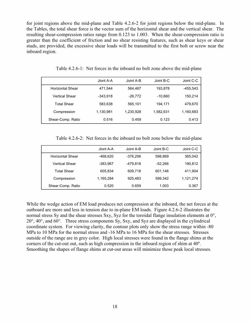
for joint regions above the mid-plane and Table 4.2.6-2 for joint regions below the mid-plane. In the Tables, the total shear force is the vector sum of the horizontal shear and the vertical shear. The resulting shear-compression ratios range from 0.123 to 1.003. When the shear-compression ratio is greater than the coefficient of friction and no shear resisting features, such as shear keys or shear studs, are provided, the excessive shear loads will be transmitted to the first bolt or screw near the inboard region. Table 4.2.6-1: Net forces in the inboard no bolt zone above the mid-plane
Table 4.2.6-2: Net forces in the inboard no bolt zone below the mid-plane
While the wedge action of EM load produces net compression at the inboard, the net forces at the outboard are more and less in tension due to in-plane EM loads. Figure 4.2.6-2 illustrates the normal stress Sy and the shear stresses Sxy, Syz for the toroidal flange insulation elements at 0°, 20°, 40°, and 60°. Three stress components Sy, Sxy, and Syz are displayed in the cylindrical coordinate system. For viewing clarity, the contour plots only show the stress range within -80 MPa to 10 MPa for the normal stress and -16 MPa to 16 MPa for the shear stresses. Stresses outside of the range are in grey color. High local stresses were found in the flange shims at the corners of the cut-out out, such as high compression in the inboard region of shim at 40º. Smoothing the shapes of flange shims at cut-out areas will minimize those peak local stresses.
Fig. 4.2.6-2: Normal stresses and shear stresses for toroidal flange insulation elements
0°
20°
40°
60°
20
Being no bolt pretension including in the analysis, the required bolt preloads shall be able to withstand the tensions and produce sufficiently frictional forces to resist the shear forces in the contact surfaces. For evaluation of bolt loads in the bolt joint, the shear force and normal force may be evaluated in a small area for a group of bolts along the flange insulation, instead of at the nodal point of each bolt location. The calculation will first selects a group of elements belonging to a group of bolts and then obtains the associated nodal points on the surface of the selected elements. A rectangular coordinate system parallel to the selected surface is defined and the nodal force components on the selected nodes are summarized. Fig. 4.2.6-3 demonstrates of nodal force sums along the flange between shell types B and C of the toroidal flange insulation elements. In the plots, Fx and Fz are the components of the net shear forces in the radial and vertical directions, respectively. The Fy is the net normal force across the joints. Positive Fz indicates that the force is out of the element and therefore is in tension. The force unit is Newton.
Fig. 4.2.6-3: Forces along the flange between shell types B and C 4.2.7 Effects of Flange Shim Geometry Two nonlinear runs filen9.db and filen9b.db were performed with slightly shape variation at the flange inboard insulation between flange joint A-A. Using the cylindrical coordinate system, Figure 4.2.7-1 shows the stress contour plots with the same contour values for elements of the original and the revised insulation shapes. In the plot, Sy is the normal stress while Sxy and Syz are the shear stress components in two perpendicular directions. Local stresses are sensitive to the shape of
Fx = -247275 Fy = 90276 Fz = 118209
Fx = 66743 Fy = -29819 Fz = 46946
Fx = 244720 Fy = 252633 Fz = 42365
Fx = -7967 Fy = -73629 Fz = -130767
Fx = 29127 Fy = -77786 Fz = -9501
Fx = 47137 Fy = -391246 Fz = 80792
Unit: Newton Fx = radial Fy = toroidal Fz = vertical
21
flange insulation at the inboard areas. A small protrusion in the insulation ends up yielding higher maximum local stresses.
Figure 4.2.7-1: Stress distributions due to shape variations in the inboard flange insulation 4.2.8 Reactions at Supports The nodal reactions at the inboard and outboard support locations are summed up and shown in Fig. 4.2.8-1 under the cylindrical coordinate system. The unit is Newton. There are no radial reactions on the supports due to no displacement restraints in that direction. The total reactions on the right-hand side supports are -96,553 N for Fθ and -347,540 N for Fz. The total reactions on the left-hand side supports are –149,280 N for Fθ and 347,540 N for Fz. Thus the total support reactions become –2.458E+6 N for Fθ and zero net reaction for Fz. Idealistically, if the support was placed on a single point, there would be zero support reactions because of the balance in the toroidal and vertical EM forces. Adding more supports will produce displacement restraints against the movement of the shell structure and thus induce reactions on the support locations. The structure will become more rigid and the deformations will become smaller. They can also carry some loadings directly to the base floor instead of balancing the loads through the toroidal flange joints. Placing the inboard and outboard supports will be more stable under the seismic loading condition. However, it produces large horizontal reactions due to the horizontal constraints. If the toroidal restraints at the inboard supports are eliminated, the horizontal reaction Fθ will be greatly reduced. Large toroidal reaction Fθ is not desirable since it will increase the difficulty in the design of the base support structure.
22
Figure 4.2.8-1: Reactions at inboard and outboard supports 4.2.9 Contact Status of Top Pads and Side Pads Figure 4.2.9-1 shows the contact status of the top pads and the side pads with MC. Examining the contact status of top pads on the modular coil surfaces illustrate that most of top pads are in near contact condition. This indicates the initial expansion of the top pad is too low and suggests that a higher temperature increase or higher CTE is needed if contact is desired. The side pads are under sliding and near contact condition. Sliding contacts on the side pads are results of the sliding between coils and tees as the pads are bonded to the clamps.
Figure 4.2.8-1: Contact status of top pads and side pads on modular coils
Pad locationsPad locations Top view
23
5.0 Summary & Commentary The analysis is for modular coil with cool-down and EM load. An initial shrinkage of coil strain 0.0004 m/m and the maximum coil current scenario of 2T high beta at t=0.0 second were selected as load input. The model assumed all surfaces in the shell structure were bonded and no bolt preloads were applied at the toroidal flanges and the poloidal breaks. The main nonlinear effect comes from the frictionless contact behavior between the winding and the winding form and between the winding and clamp assembly. There are 5MN of net radial EM forces induced by the modular coils in one field period. The vertical forces Fz and the toroidal forces Fθ are equal and opposite in direction for the coils in the right-hand side and the left-hand side, resulting in zero net forces. The EM load produces wedge action at the inboard leg region. Out side the region, the net forces in the shell are generally in tension. The shell structure is made of stainless steel casting. According to the NCSX design criteria (see Ref. [9]), the allowable stress for the membrane plus bending will be 322.5 MPa or 46.78 ksi, which is larger than the maximum stress. The maximum deflection in the shell is 2.336 mm in the tee of the shell type B. Maximum axial stress in the modular coil is 253 MPa, located locally at coil type A at where the coil winding extend beyond the edge of shell and the radius of winding curvature is small. The value is conservative because of non-homogeneous current flow and large mesh size. Away from the local stress area, all stresses are below 140 MPa. The maximum displacement is 2.707 mm in the coil type C. The peak von Mises stress in the clamp is 283 MPa, based on the rigid mount of clamp to the tee. If sliding and rotation are allowed in the clamp assembly, the maximum stress will be much lower. If the Belleville washers in the clamp could handle the coil movements, the stress in the clamp should be relatively constant. As the clamp assembly may not be able to confine the movement of the modular coil, an option is to remove the particular clamp when the displacement of coil is too large for the clamp. The contact pressures on the wing bags are far from uniform. The contact surfaces are assumed to be bonded to the shells. The maximum contact pressure on the wind bag is 136 MPa (19.7 ksi), which is more or less proportional to its stiffness. The tensile stress area in the wing bag is not effective for the load transfer. A shape change to minimized the tensile region will result in a more even stress distribution and lower compression. If the actual wing bags are not bonded to the shell, the contact surface behavior should be modified. The distributions of contact pressure on the poloidal break spacers are more even, except the narrow section in the tee. The net force in the poloidal break is in tension. The bolt preload will be designed to overcome the tensile stresses and shear stresses. There are no bolts available in the inboard regions of the toroidal flange shims. The calculations show the shear-compression ratios range from 0.123 to 1.003, greater than the hypothetical coefficient of friction, said 0.3. The coefficient of friction between two surfaces relates to the surface preparation and contact materials. If there are no additional shear resisting features, some shearing forces may transmit to the first bolt or screw in the inboard regions. To simulate this condition appropriately, the contact behavior should be changed from bonding to standard contact.
24
High local stresses were found in the flange shims at the corners of the cut-out such as compression in the inboard region at 40º (see Fig. 4.2.6-2). Smoothing the shapes of flange shimrs will minimize those peak local stresses. Choosing the supports in the mid-span of the shell type C will induce tensile reactions in the support structure. The elimination of the toroidal restraints at the inboard supports will greatly reduce the horizontal reaction in the supports. As the coil shrinkage during cool-down is the main factor of the nonlinear behavior, the assumption that the initial coil shrinkage strain of 0.0004 m/m should be verified and confirmed. Finally this analysis is only for a governing load case with modular coil cool-down and EM load. The complete analysis shall include all possible load conditions. 5.0 References [1] C08R00_c3.XLS, dated 1/13/2004, PPPL web site ncsx.pppl.gov/NCSX_Engineering/Requirements/Specs/GRD/Rev1/TDS_XL_C08R00_c3.pdf [2] C08R00_C7.xls, dated 9/1/2005, PPPL web site ncsx.pppl.gov/NCSX_Engineering/Requirements/Specs/GRD/Rev3/C08R00_C7.pdf [3] T. Kozub, “NCSX Composite Coil Tests”, March 15, 2004, PPPL web site ncsx.pppl.gov//NCSX_Engineering/Meetings/CY-2004/March/040315_MatlTest/ [4] T. Kozub, “NCSX Composite Coil Tests”, April 5, 2004, PPPL web site ncsx.pppl.gov//NCSX_Engineering/Meetings/CY-2004/March/040405_MatlTest/ [5] L. Myatt, “Transverse Compression of Modular Coil Conductor from ANSYS”, April 13, 2004, PPPL web site: ncsx.pppl.gov/NCSX_Engineering/Meetings/CY-2004/April/040412_MatlTest/ [6] H. Fan, “Nonlinear Analysis of Modular Coils and Shell Structure for Coil Cool-down and EM Loads, Part 1 – Results of Shell Structure and Modular Coils”, September 28, 2005, E-mail attachment. [7] H. Fan, “Nonlinear Analysis of Modular Coils and Shell Structure for Coil Cool-down and EM Loads, Part 2 – Results of Clamp Assembly, Wing Bags, Poloidal Break Joint, and Flange Spacer Joints”, November 15, 2005, E-mail attachment. [8] NCSX Product Specification, “Modular Coil Windings Forms”, NCSX-CSPEC-141-03-10, November 15, 2005 [9] I. Zatz, Editor, “NCSX Structural Design Criteria, Draft E”, May 10, 2004, PPPL web site: ncsx.pppl.gov//Meetings/FDR_2004/FDR_docs/Postings/NCSX-CRIT-CRYO-00-dE.pdf/