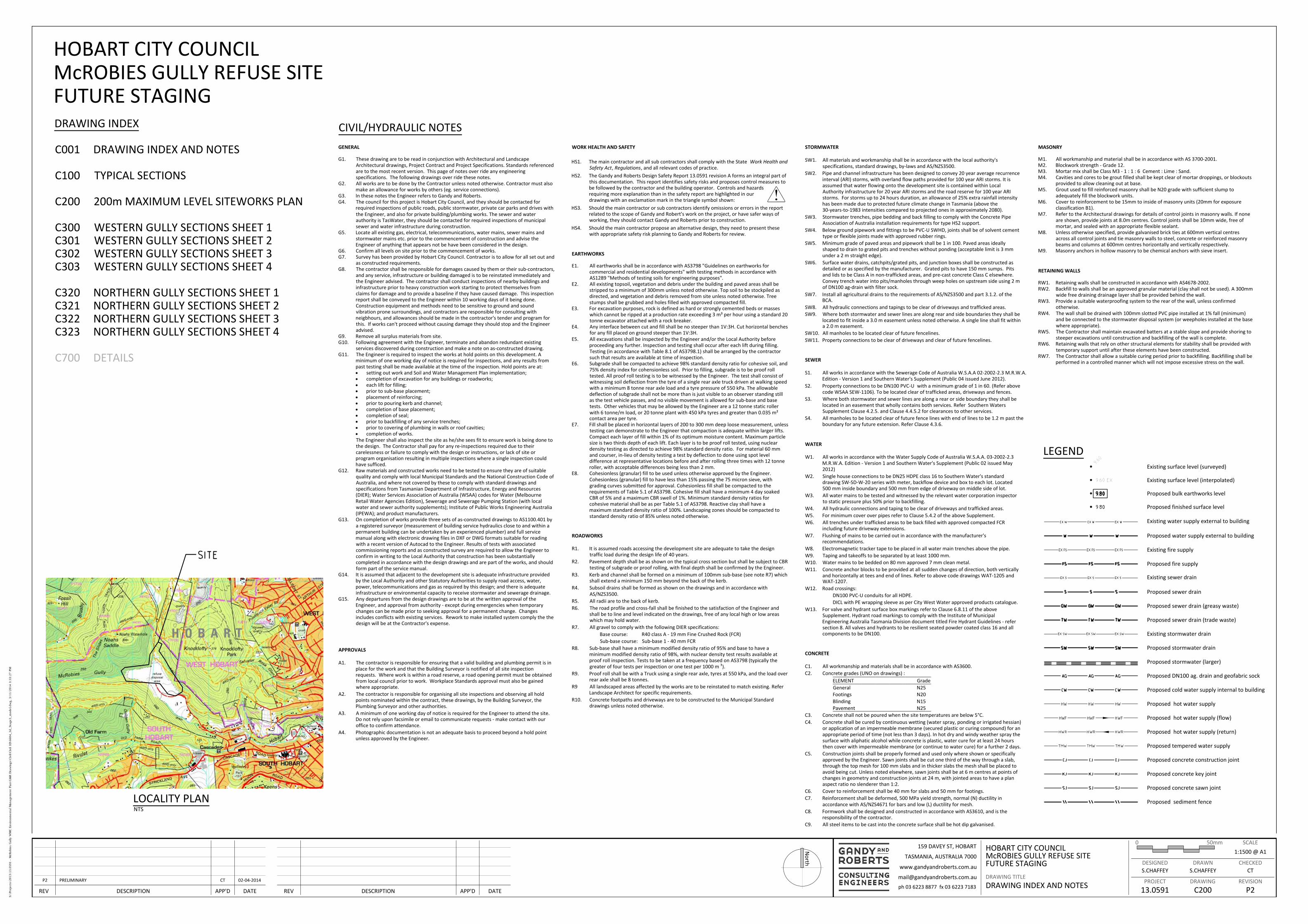
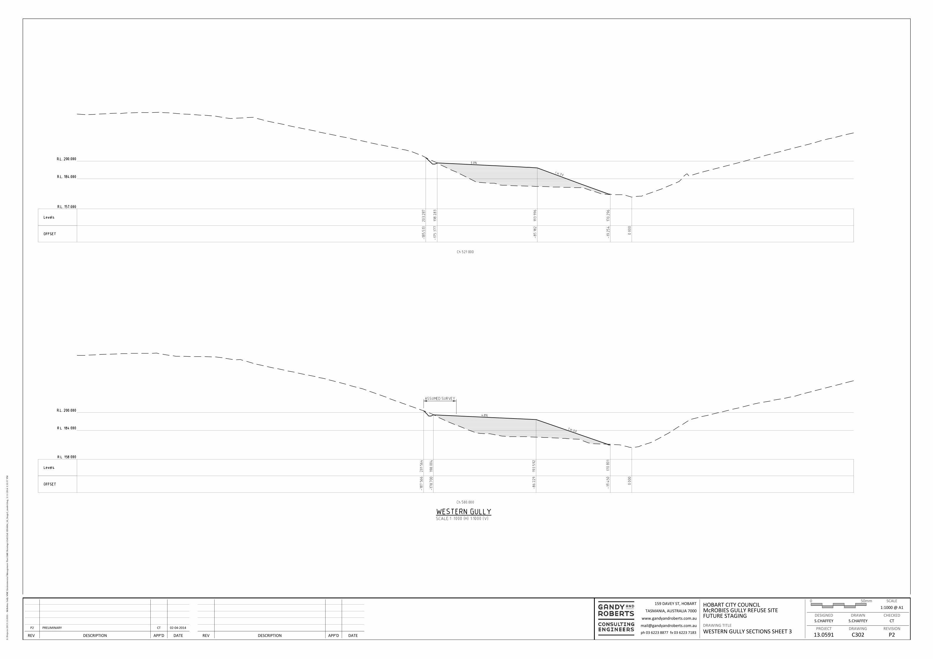
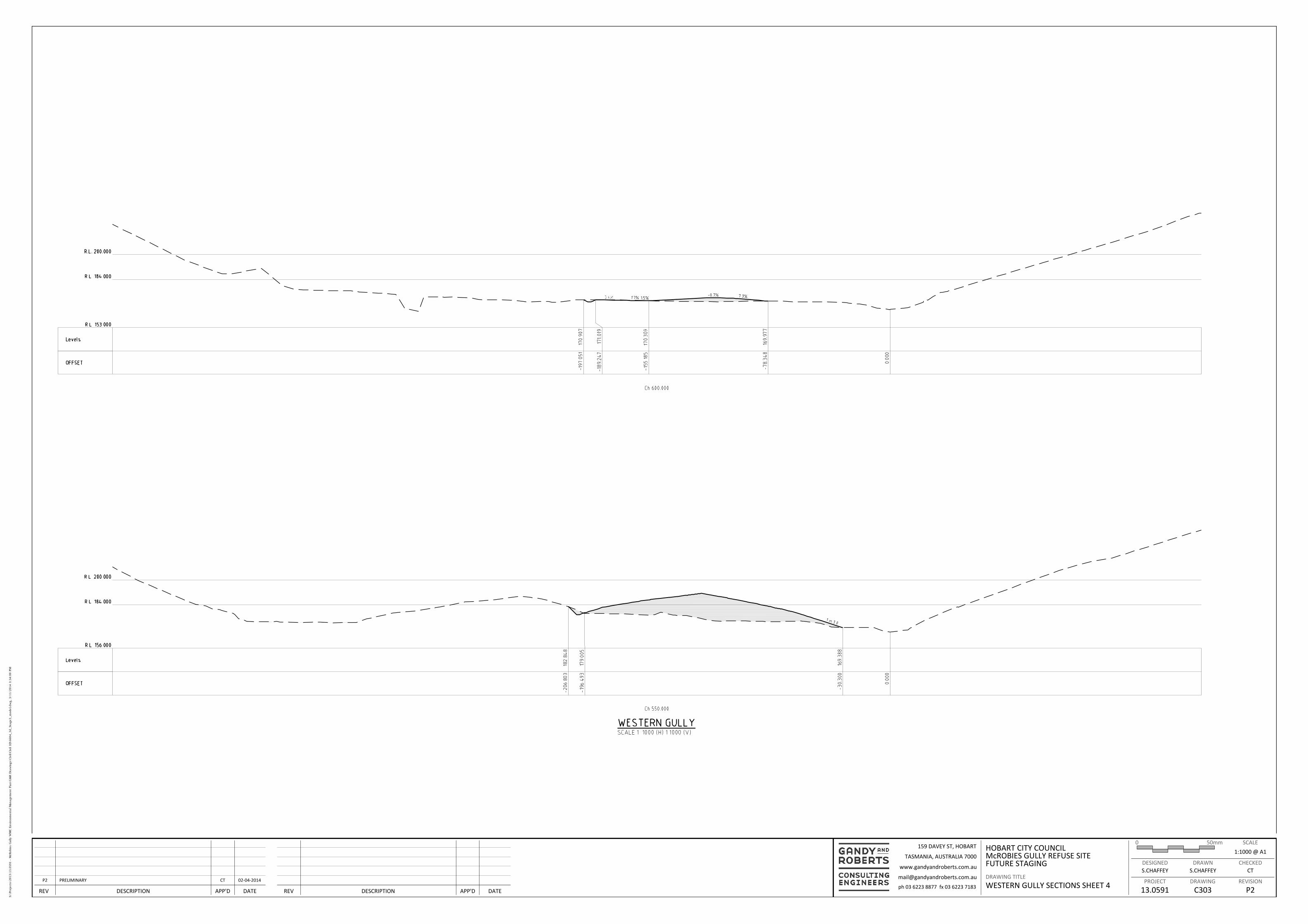
+ All Categories
Home > Documents > HOBART CITY COUNCIL McROBIES GULLY REFUSE SITEepa.tas.gov.au/documents/city of hobart, mcrobies...

HOBART CITY COUNCIL McROBIES GULLY REFUSE SITEepa.tas.gov.au/documents/city of hobart, mcrobies...

Date post: 05-Jun-2018
Category:
Upload: doancong
View: 215 times
Download: 0 times
Share this document with a friend
11
0 50mm DESIGNED PROJECT DRAWN DRAWING CHECKED REVISION SCALE DRAWING TITLE REV DESCRIPTION APP'D DATE REV DESCRIPTION APP'D DATE 159 DAVEY ST, HOBART TASMANIA, AUSTRALIA 7000 www.gandyandroberts.com.au ph 03 6223 8877 fx 03 6223 7183 [email protected] HOBART CITY COUNCIL McROBIES GULLY REFUSE SITE FUTURE STAGING DRAWING INDEX AND NOTES S.CHAFFEY S.CHAFFEY CT 1:1500 @ A1 13.0591 C200 P2 P2 PRELIMINARY CT 02-04-2014 HOBART CITY COUNCIL McROBIES GULLY REFUSE SITE FUTURE STAGING DRAWING INDEX C001 DRAWING INDEX AND NOTES C100 TYPICAL SECTIONS C200 200m MAXIMUM LEVEL SITEWORKS PLAN C300 WESTERN GULLY SECTIONS SHEET 1 C301 WESTERN GULLY SECTIONS SHEET 2 C302 WESTERN GULLY SECTIONS SHEET 3 C303 WESTERN GULLY SECTIONS SHEET 4 C320 NORTHERN GULLY SECTIONS SHEET 1 C321 NORTHERN GULLY SECTIONS SHEET 2 C322 NORTHERN GULLY SECTIONS SHEET 3 C323 NORTHERN GULLY SECTIONS SHEET 4 C700 DETAILS LEGEND Proposed stormwater drain Proposed DN100 ag. drain and geofabric sock Existing water supply external to building Proposed bulk earthworks level Existing sewer drain Proposed sewer drain Proposed water supply external to building Proposed cold water supply internal to building Proposed hot water supply Proposed tempered water supply Existing stormwater drain Existing surface level (interpolated) Proposed concrete sawn joint Proposed fire supply Proposed concrete construction joint Existing fire supply LOCALITY PLAN NTS Existing surface level (surveyed) Proposed finished surface level Proposed sewer drain (greasy waste) Proposed sewer drain (trade waste) Proposed hot water supply (flow) Proposed hot water supply (return) Proposed sediment fence Proposed stormwater (larger) Proposed concrete key joint CIVIL/HYDRAULIC NOTES GENERAL G1. These drawing are to be read in conjunction with Architectural and Landscape Architectural drawings, Project Contract and Project Specifications. Standards referenced are to the most recent version. This page of notes over ride any engineering specifications. The following drawings over ride these notes. G2. All works are to be done by the Contractor unless noted otherwise. Contractor must also make an allowance for works by others (eg. service connections). G3. In these notes the Engineer refers to Gandy and Roberts. G4. The council for this project is Hobart City Council, and they should be contacted for required inspections of public roads, public stormwater, private car parks and drives with the Engineer, and also for private building/plumbing works. The sewer and water authority is TasWater, they should be contacted for required inspections of municipal sewer and water infrastructure during construction. G5. Locate all existing gas, electrical, telecommunications, water mains, sewer mains and stormwater mains etc. prior to the commencement of construction and advise the Engineer of anything that appears not be have been considered in the design. G6. Confirm all levels on site prior to the commencement of works. G7. Survey has been provided by Hobart City Council. Contractor is to allow for all set out and as constructed requirements. G8. The contractor shall be responsible for damages caused by them or their sub-contractors, and any service, infrastructure or building damaged is to be reinstated immediately and ƚŚĞ ŶŐŝŶĞĞƌ ĂĚǀŝƐĞĚ dŚĞ ĐŽŶƚƌĂĐƚŽƌ ƐŚĂůů ĐŽŶĚƵĐƚ ŝŶƐƉĞĐƚŝŽŶƐ ŽĨ ŶĞĂƌďLJ ďƵŝůĚŝŶŐƐ ĂŶĚ infrastructure prior to heavy construction work starting to protect themselves from ĐůĂŝŵƐ ĨŽƌ ĚĂŵĂŐĞ ĂŶĚ ƚŽ ƉƌŽǀŝĚĞ Ă ďĂƐĞůŝŶĞ ŝĨ ƚŚĞLJ ŚĂǀĞ ĐĂƵƐĞĚ ĚĂŵĂŐĞ dŚŝƐ ŝŶƐƉĞĐƚŝŽŶ ƌĞƉŽƌƚ ƐŚĂůů ďĞ ĐŽŶǀĞLJĞĚ ƚŽ ƚŚĞ ŶŐŝŶĞĞƌ ǁŝƚŚŝŶ ϭϬ ǁŽƌŬŝŶŐ ĚĂLJƐ ŽĨ ŝƚ ďĞŝŶŐ ĚŽŶĞ Construction equipment and methods need to be sensitive to ground and sound vibration prone surroundings, and contractors are responsible for consulting with neigbhours, and allowances should be made in the contractor's tender and program for ƚŚŝƐ /Ĩ ǁŽƌŬƐ ĐĂŶΖƚ ƉƌŽĐĞĞĚ ǁŝƚŚŽƵƚ ĐĂƵƐŝŶŐ ĚĂŵĂŐĞ ƚŚĞLJ ƐŚŽƵůĚ ƐƚŽƉ ĂŶĚ ƚŚĞ ŶŐŝŶĞĞƌ advised. G9. Remove all surplus materials from site. G10. Following agreement with the Engineer, terminate and abandon redundant existing services discovered during construction and make a note on as-constructed drawing. G11. The Engineer is required to inspect the works at hold points on this development. A minimum of one working day of notice is required for inspections, and any results from past testing shall be made available at the time of the inspection. Hold points are at: x setting out work and Soil and Water Management Plan implementation; x completion of excavation for any buildings or roadworks; x each lift for filling; x prior to sub-base placement; x placement of reinforcing; x prior to pouring kerb and channel; x completion of base placement; x completion of seal; x prior to backfilling of any service trenches; x prior to covering of plumbing in walls or roof cavities; x completion of works. The Engineer shall also inspect the site as he/she sees fit to ensure work is being done to the design. The Contractor shall pay for any re-inspections required due to their carelessness or failure to comply with the design or instructions, or lack of site or program organisation resulting in multiple inspections where a single inspection could have sufficed. G12. Raw materials and constructed works need to be tested to ensure they are of suitable quality and comply with local Municipal Standards and the National Construction Code of Australia, and where not covered by these to comply with standard drawings and specifications from Tasmanian Department of Infrastructure, Energy and Resources (DIER); Water Services Association of Australia (WSAA) codes for Water (Melbourne Retail Water Agencies Edition), Sewerage and Sewerage Pumping Station (with local water and sewer authority supplements); Institute of Public Works Engineering Australia (IPEWA); and product manufacturers. G13. On completion of works provide three sets of as-constructed drawings to AS1100.401 by a registered surveyor (measurement of building service hydraulics close to and within a permanent building can be undertaken by an experienced plumber) and full service manual along with electronic drawing files in DXF or DWG formats suitable for reading with a recent version of Autocad to the Engineer. Results of tests with associated commissioning reports and as constructed survey are required to allow the Engineer to confirm in writing to the Local Authority that construction has been substantially completed in accordance with the design drawings and are part of the works, and should form part of the service manual. G14. It is assumed that adjacent to the development site is adequate infrastructure provided by the Local Authority and other Statutory Authorities to supply road access, water, power, telecommunications and gas as required by this design; and there is adequate infrastructure or environmental capacity to receive stormwater and sewerage drainage. G15. Any departures from the design drawings are to be at the written approval of the Engineer, and approval from authority - except during emergencies when temporary changes can be made prior to seeking approval for a permanent change. Changes includes conflicts with existing services. Rework to make installed system comply the the design will be at the Contractor's expense. EARTHWORKS E1. All earthworks shall be in accordance with AS3798 "Guidelines on earthworks for commercial and residential developments" with testing methods in accordance with AS1289 "Methods of testing soils for engineering purposes". E2. All existing topsoil, vegetation and debris under the building and paved areas shall be stripped to a minimum of 300mm unless noted otherwise. Top soil to be stockpiled as directed, and vegetation and debris removed from site unless noted otherwise. Tree stumps shall be grubbed and holes filled with approved compacted fill. E3. For excavation purposes, rock is defined as hard or strongly cemented beds or masses ǁŚŝĐŚ ĐĂŶŶŽƚ ďĞ ƌŝƉƉĞĚ Ăƚ Ă ƉƌŽĚƵĐƚŝŽŶ ƌĂƚĞ ĞdžĐĞĞĚŝŶŐ ϯ ŵϹ ƉĞƌ ŚŽƵƌ ƵƐŝŶŐ Ă ƐƚĂŶĚĂƌĚ ϮϬ tonne excavator attached with a rock breaker. E4. Any interface between cut and fill shall be no steeper than 1V:3H. Cut horizontal benches for any fill placed on ground steeper than 1V:3H. E5. All excavations shall be inspected by the Engineer and/or the Local Authority before proceeding any further. Inspection and testing shall occur after each lift during filling. Testing (in accordance with Table 8.1 of AS3798.1) shall be arranged by the contractor such that results are available at time of inspection. E6. Subgrade shall be compacted to achieve 98% standard density ratio for cohesive soil, and 75% density index for cohensionless soil. Prior to filling, subgrade is to be proof roll tested. All proof roll testing is to be witnessed by the Engineer. The test shall consist of witnessing soil deflection from the tyre of a single rear axle truck driven at walking speed with a minimum 8 tonne rear axle load and a tyre pressure of 550 kPa. The allowable deflection of subgrade shall not be more than is just visible to an observer standing still as the test vehicle passes, and no visible movement is allowed for sub-base and base ƚĞƐƚƐ KƚŚĞƌ ǀĞŚŝĐůĞƐ ƚŚĂƚ ŵĂLJ ďĞ ĂůůŽǁĞĚ ďLJ ƚŚĞ ŶŐŝŶĞĞƌ ĂƌĞ Ă ϭϮ ƚŽŶŶĞ ƐƚĂƚŝĐ ƌŽůůĞƌ ǁŝƚŚ ϲ ƚŽŶŶĞŵ ůŽĂĚ Žƌ ϮϬ ƚŽŶŶĞ ƉůĂŶƚ ǁŝƚŚ ϰϱϬ ŬWĂ ƚLJƌĞƐ ĂŶĚ ŐƌĞĂƚĞƌ ƚŚĂŶ ϬϬϯϱ ŵϸ contact area per tyre. E7. Fill shall be placed in horizontal layers of 200 to 300 mm deep loose measurement, unless testing can demonstrate to the Engineer that compaction is adequate within larger lifts. Compact each layer of fill within 1% of its optimum moisture content. Maximum particle size is two thirds depth of each lift. Each layer is to be proof roll tested, using nuclear density testing as directed to achieve 98% standard density ratio. For material 60 mm and courser, in-lieu of density testing a test by deflection to done using spot level difference at representative locations before and after rolling three times with 12 tonne roller, with acceptable differences being less than 2 mm. E8. Cohesionless (granular) fill to be used unless otherwise approved by the Engineer. Cohesionless (granular) fill to have less than 15% passing the 75 micron sieve, with grading curves submitted for approval. Cohesionless fill shall be compacted to the requirements of Table 5.1 of AS3798. Cohesive fill shall have a minimum 4 day soaked CBR of 5% and a maximum CBR swell of 1%. Minimum standard density ratios for cohesive material shall be as per Table 5.1 of AS3798. Reactive clay shall have a maximum standard density ratio of 100%. Landscaping zones should be compacted to standard density ratio of 85% unless noted otherwise. CONCRETE C1. All workmanship and materials shall be in accordance with AS3600. C2. Concrete grades (UNO on drawings) : ELEMENT Grade General N25 Footings N20 Blinding N15 Pavement N25 C3. ŽŶĐƌĞƚĞ ƐŚĂůů ŶŽƚ ďĞ ƉŽƵƌĞĚ ǁŚĞŶ ƚŚĞ ƐŝƚĞ ƚĞŵƉĞƌĂƚƵƌĞƐ ĂƌĞ ďĞůŽǁ ϱΣ C4. Concrete shall be cured by continuous wetting (water spray, ponding or irrigated hessian) or application of an impermeable membrane (secured plastic or curing compound) for an appropriate period of time (not less than 3 days). In hot dry and windy weather spray the surface with aliphatic alcohol while concrete is plastic, water cure for at least 24 hours then cover with impermeable membrane (or continue to water cure) for a further 2 days. C5. Construction joints shall be properly formed and used only where shown or specifically approved by the Engineer. Sawn joints shall be cut one third of the way through a slab, through the top mesh for 100 mm slabs and in thicker slabs the mesh shall be placed to avoid being cut. Unless noted elsewhere, sawn joints shall be at 6 m centres at points of ĐŚĂŶŐĞƐ ŝŶ ŐĞŽŵĞƚƌLJ ĂŶĚ ĐŽŶƐƚƌƵĐƚŝŽŶ ũŽŝŶƚƐ Ăƚ Ϯϰ ŵ ǁŝƚŚ ũŽŝŶƚĞĚ ĂƌĞĂƐ ƚŽ ŚĂǀĞ Ă ƉůĂŶ aspect ratio no slenderer than 1:2. C6. ŽǀĞƌ ƚŽ ƌĞŝŶĨŽƌĐĞŵĞŶƚ ƐŚĂůů ďĞ ϰϬ ŵŵ ĨŽƌ ƐůĂďƐ ĂŶĚ ϱϬ ŵŵ ĨŽƌ ĨŽŽƚŝŶŐƐ C7. Reinforcement shall be deformed, 500 MPa yield strength, normal (N) ductility in accordance with AS/NZS4671 for bars and low (L) ductility for mesh. C8. Formwork shall be designed and constructed in accordance with AS3610, and is the responsibility of the contractor. C9. All steel items to be cast into the concrete surface shall be hot dip galvanised. ROADWORKS R1. It is assumed roads accessing the development site are adequate to take the design traffic load during the design life of 40 years. R2. Pavement depth shall be as shown on the typical cross section but shall be subject to CBR testing of subgrade or proof rolling, with final depth shall be confirmed by the Engineer. R3. Kerb and channel shall be formed on a minimum of 100mm sub-base (see note R7) which ƐŚĂůů ĞdžƚĞŶĚ Ă ŵŝŶŝŵƵŵ ϭϱϬ ŵŵ ďĞLJŽŶĚ ƚŚĞ ďĂĐŬ ŽĨ ƚŚĞ ŬĞƌď R4. Subsoil drains shall be formed as shown on the drawings and in accordance with AS/NZS3500. R5. All radii are to the back of kerb. R6. The road profile and cross-fall shall be finished to the satisfaction of the Engineer and shall be to line and level indicated on the drawings, free of any local high or low areas which may hold water. R7. All gravel to comply with the following DIER specifications: Base course: ZϰϬ ĐůĂƐƐ Ͳ ϭϵ ŵŵ &ŝŶĞ ƌƵƐŚĞĚ ZŽĐŬ ;&ZͿ Sub-base course: ^ƵďͲďĂƐĞ ϭ Ͳ ϰϬ ŵŵ &Z R8. Sub-base shall have a minimum modified density ratio of 95% and base to have a minimum modified density ratio of 98%, with nuclear density test results available at proof roll inspection. Tests to be taken at a frequency based on AS3798 (typically the greater of four tests per inspection or one test per 1000 m á). R9. WƌŽŽĨ ƌŽůů ƐŚĂůů ďĞ ǁŝƚŚ Ă dƌƵĐŬ ƵƐŝŶŐ Ă ƐŝŶŐůĞ ƌĞĂƌ ĂdžůĞ ƚLJƌĞƐ Ăƚ ϱϱϬ ŬWĂ ĂŶĚ ƚŚĞ ůŽĂĚ ŽǀĞƌ rear axle shall be 8 tonnes. R9 All landscaped areas affected by the works are to be reinstated to match existing. Refer Landscape Architect for specific requirements. R10. Concrete footpaths and driveways are to be constructed to the Municipal Standard drawings unless noted otherwise. STORMWATER SW1. All materials and workmanship shall be in accordance with the local authority's specifications, standard drawings, by-laws and AS/NZS3500. SW2. Pipe and channel infrastructure has been designed to convey 20 year average recurrence interval (ARI) storms, with overland flow paths provided for 100 year ARI storms. It is assumed that water flowing onto the development site is contained within Local Authority infrastructure for 20 year ARI storms and the road reserve for 100 year ARI storms. For storms up to 24 hours duration, an allowance of 25% extra rainfall intensity has been made due to protected future climate change in Tasmania (above the 30-years-to-1983 intensities compared to projected ones in approximately 2080). SW3. Stormwater trenches, pipe bedding and back filling to comply with the Concrete Pipe Association of Australia installation requirements for type HS2 support. SW4. Below ground pipework and fittings to be PVC-U SWHD, joints shall be of solvent cement type or flexible joints made with approved rubber rings. SW5. Minimum grade of paved areas and pipework shall be 1 in 100. Paved areas ideally shaped to drain to grated pits and trenches without ponding (acceptable limit is 3 mm under a 2 m straight edge). SW6. Surface water drains, catchpits/grated pits, and junction boxes shall be constructed as detailed or as specified by the manufacturer. Grated pits to have 150 mm sumps. Pits and lids to be Class A in non-trafficked areas, and pre-cast concrete Class C elsewhere. ŽŶǀĞLJ ƚƌĞŶĐŚ ǁĂƚĞƌ ŝŶƚŽ ƉŝƚƐŵĂŶŚŽůĞƐ ƚŚƌŽƵŐŚ ǁĞĞƉ ŚŽůĞƐ ŽŶ ƵƉƐƚƌĞĂŵ ƐŝĚĞ ƵƐŝŶŐ Ϯ ŵ of DN100 ag-drain with filter sock. SW7. Install all agricultural drains to the requirements of AS/NZS3500 and part 3.1.2. of the BCA. SW8. All hydraulic connections and tapings to be clear of driveways and trafficked areas. SW9. Where both stormwater and sewer lines are along rear and side boundaries they shall be ůŽĐĂƚĞĚ ƚŽ Ĩŝƚ ŝŶƐŝĚĞ Ă ϯϬ ŵ ĞĂƐĞŵĞŶƚ ƵŶůĞƐƐ ŶŽƚĞĚ ŽƚŚĞƌǁŝƐĞ ƐŝŶŐůĞ ůŝŶĞ ƐŚĂůů Ĩŝƚ ǁŝƚŚŝŶ Ă ϮϬ ŵ ĞĂƐĞŵĞŶƚ SW10. All manholes to be located clear of future fencelines. SW11. Property connections to be clear of driveways and clear of future fencelines. WATER W1. All works in accordance with the Water Supply Code of Australia W.S.A.A. 03-2002-2.3 M.R.W.A. Edition - Version 1 and Southern Water's Supplement (Public 02 issued May 2012) W2. Single house connections to be DN25 HDPE class 16 to Southern Water's standard drawing SW-SD-W-20 series with meter, backflow device and box to each lot. Located 500 mm inside boundary and 500 mm from edge of driveway on middle side of lot. W3. All water mains to be tested and witnessed by the relevant water corporation inspector to static pressure plus 50% prior to backfilling. W4. All hydraulic connections and taping to be clear of driveways and trafficked areas. W5. For minimum cover over pipes refer to Clause 5.4.2 of the above Supplement. W6. All trenches under trafficked areas to be back filled with approved compacted FCR including future driveway extensions. W7. Flushing of mains to be carried out in accordance with the manufacturer's recommendations. W8. Electromagnetic tracker tape to be placed in all water main trenches above the pipe. W9. dĂƉŝŶŐ ĂŶĚ ƚĂŬĞŽĨĨƐ ƚŽ ďĞ ƐĞƉĂƌĂƚĞĚ ďLJ Ăƚ ůĞĂƐƚ ϭϬϬϬ ŵŵ W10. tĂƚĞƌ ŵĂŝŶƐ ƚŽ ďĞ ďĞĚĚĞĚ ŽŶ ϴϬ ŵŵ ĂƉƉƌŽǀĞĚ ϳ ŵŵ ĐůĞĂŶ ŵĞƚĂů W11. Concrete anchor blocks to be provided at all sudden changes of direction, both vertically and horizontally at tees and end of lines. Refer to above code drawings WAT-1205 and WAT-1207. W12. Road crossings: DN100 PVC-U conduits for all HDPE. DICL with PE wrapping sleeve as per City West Water approved products catalogue. W13. For valve and hydrant surface box markings refer to Clause 6.8.11 of the above Supplement. Hydrant road markings to comply with the Institute of Municipal Engineering Australia Tasmania Division document titled Fire Hydrant Guidelines - refer section 8. All valves and hydrants to be resilient seated powder coated class 16 and all components to be DN100. APPROVALS A1. The contractor is responsible for ensuring that a valid building and plumbing permit is in place for the work and that the Building Surveyor is notified of all site inspection requests. Where work is within a road reserve, a road opening permit must be obtained from local council prior to work. Workplace Standards approval must also be gained where appropriate. A2. The contractor is responsible for organising all site inspections and observing all hold points nominated within the contract, these drawings, by the Building Surveyor, the Plumbing Surveyor and other authorities. A3. A minimum of one working day of notice is required for the Engineer to attend the site. Do not rely upon facsimile or email to communicate requests - make contact with our office to confirm attendance. A4. Photographic documentation is not an adequate basis to proceed beyond a hold point unless approved by the Engineer. SEWER S1. All works in accordance with the Sewerage Code of Australia W.S.A.A 02-2002-2.3 M.R.W.A. Edition - Version 1 and Southern Water's Supplement (Public 04 issued June 2012). S2. Property connections to be DN100 PVC-U with a minimum grade of 1 in 60. (Refer above code WSAA SEW-1106). To be located clear of trafficked areas, driveways and fences. S3. Where both stormwater and sewer lines are along a rear or side boundary they shall be located in an easement that wholly contains both services. Refer Southern Waters Supplement Clause 4.2.5. and Clause 4.4.5.2 for clearances to other services. S4. All manholes to be located clear of future fence lines with end of lines to be 1.2 m past the boundary for any future extension. Refer Clause 4.3.6. WORK HEALTH AND SAFETY ,^ϭ dŚĞ ŵĂŝŶ ĐŽŶƚƌĂĐƚŽƌ ĂŶĚ Ăůů ƐƵď ĐŽŶƚƌĂĐƚŽƌƐ ƐŚĂůů ĐŽŵƉůLJ ǁŝƚŚ ƚŚĞ ^ƚĂƚĞ Work Health and Safety Act , Regulations, and all relevant codes of practice. ,^Ϯ dŚĞ 'ĂŶĚLJ ĂŶĚ ZŽďĞƌƚƐ ĞƐŝŐŶ ^ĂĨĞƚLJ ZĞƉŽƌƚ ϭϯϬϱϵϭ ƌĞǀŝƐŝŽŶ ĨŽƌŵƐ ĂŶ ŝŶƚĞŐƌĂů ƉĂƌƚ ŽĨ ƚŚŝƐ ĚŽĐƵŵĞŶƚĂƚŝŽŶ dŚŝƐ ƌĞƉŽƌƚ ŝĚĞŶƚŝĨŝĞƐ ƐĂĨĞƚLJ ƌŝƐŬƐ ĂŶĚ ƉƌŽƉŽƐĞƐ ĐŽŶƚƌŽů ŵĞĂƐƵƌĞƐ ƚŽ ďĞ ĨŽůůŽǁĞĚ ďLJ ƚŚĞ ĐŽŶƚƌĂĐƚŽƌ ĂŶĚ ƚŚĞ ďƵŝůĚŝŶŐ ŽƉĞƌĂƚŽƌ ŽŶƚƌŽůƐ ĂŶĚ ŚĂnjĂƌĚƐ requiring more explanation than in the safety report are highlighted in our drawings with an exclamation mark in the triangle symbol shown: ,^ϯ ^ŚŽƵůĚ ƚŚĞ ŵĂŝŶ ĐŽŶƚƌĂĐƚŽƌ Žƌ ƐƵď ĐŽŶƚƌĂĐƚŽƌƐ ŝĚĞŶƚŝĨLJ ŽŵŝƐƐŝŽŶƐ Žƌ ĞƌƌŽƌƐ ŝŶ ƚŚĞ ƌĞƉŽƌƚ related to the scope of Gandy and Robert's work on the project, or have safer ways of working, they should contact Gandy and Roberts prior to construction. ,^ϰ ^ŚŽƵůĚ ƚŚĞ ŵĂŝŶ ĐŽŶƚƌĂĐƚŽƌ ƉƌŽƉŽƐĞ ĂŶ ĂůƚĞƌŶĂƚŝǀĞ ĚĞƐŝŐŶ ƚŚĞLJ ŶĞĞĚ ƚŽ ƉƌĞƐĞŶƚ ƚŚĞƐĞ with appropriate safety risk planning to Gandy and Roberts for review. RETAINING WALLS RW1. Retaining walls shall be constructed in accordance with AS4678-2002. RW2. Backfill to walls shall be an approved granular material (clay shall not be used). A 300mm wide free draining drainage layer shall be provided behind the wall. RW3. Provide a suitable waterproofing system to the rear of the wall, unless confirmed otherwise. RW4. The wall shall be drained with 100mm slotted PVC pipe installed at 1% fall (minimum) and be connected to the stormwater disposal system (or weepholes installed at the base where appropriate). RW5. The Contractor shall maintain excavated batters at a stable slope and provide shoring to steeper excavations until construction and backfilling of the wall is complete. RW6. Retaining walls that rely on other structural elements for stability shall be provided with temporary support until after these elements have been constructed. RW7. The Contractor shall allow a suitable curing period prior to backfilling. Backfilling shall be performed in a controlled manner which will not impose excessive stress on the wall. MASONRY M1. All workmanship and material shall be in accordance with AS 3700-2001. M2. Blockwork strength - Grade 12. M3. Mortar mix shall be Class M3 - 1 : 1 : 6 Cement : Lime : Sand. M4. Cavities and cores to be grout filled shall be kept clear of mortar droppings, or blockouts provided to allow cleaning out at base. M5. Grout used to fill reinforced masonry shall be N20 grade with sufficient slump to adequately fill the blockwork units. M6. Cover to reinforcement to be 15mm to inside of masonry units (20mm for exposure classification B1). M7. Refer to the Architectural drawings for details of control joints in masonry walls. If none are shown, provide joints at 8.0m centres. Control joints shall be 10mm wide, free of mortar, and sealed with an appropriate flexible sealant. M8. Unless otherwise specified, provide galvanised brick ties at 600mm vertical centres across all control joints and tie masonry walls to steel, concrete or reinforced masonry beams and columns at 600mm centres horizontally and vertically respectively. M9. Masonry anchors in hollow masonry to be chemical anchors with sieve insert. S:\Projects\2013\13.0591 - McRobies Gully WMC Environmental Management Plan\G&R Drawings\Civil\Civil 3D\6604_3d_Stage3_model.dwg, 3/11/2014 3:33:27 PM
Transcript

0 50mm

DESIGNED

PROJECT

DRAWN

DRAWING

CHECKED

REVISION

SCALE

DRAWING TITLE

REV DESCRIPTION APP'D DATEREV DESCRIPTION APP'D DATE

159 DAVEY ST, HOBART

TASMANIA, AUSTRALIA 7000

www.gandyandroberts.com.au

ph 03 6223 8877 fx 03 6223 7183

[email protected]

HOBART CITY COUNCILMcROBIES GULLY REFUSE SITEFUTURE STAGING

DRAWING INDEX AND NOTES

S.CHAFFEY S.CHAFFEY CT

1:1500 @ A1

13.0591 C200 P2P2 PRELIMINARY CT 02-04-2014

HOBART CITY COUNCILMcROBIES GULLY REFUSE SITEFUTURE STAGINGDRAWING INDEX

C001 DRAWING INDEX AND NOTES

C100 TYPICAL SECTIONS

C200 200m MAXIMUM LEVEL SITEWORKS PLAN

C300 WESTERN GULLY SECTIONS SHEET 1C301 WESTERN GULLY SECTIONS SHEET 2C302 WESTERN GULLY SECTIONS SHEET 3C303 WESTERN GULLY SECTIONS SHEET 4

C320 NORTHERN GULLY SECTIONS SHEET 1C321 NORTHERN GULLY SECTIONS SHEET 2C322 NORTHERN GULLY SECTIONS SHEET 3C323 NORTHERN GULLY SECTIONS SHEET 4

C700 DETAILS

LEGEND

Proposed stormwater drain

Proposed DN100 ag. drain and geofabric sock

Existing water supply external to building

Proposed bulk earthworks level

Existing sewer drain

Proposed sewer drain

Proposed water supply external to building

Proposed cold water supply internal to building

Proposed hot water supply

Proposed tempered water supply

Existing stormwater drain

Existing surface level (interpolated)

Proposed concrete sawn joint

Proposed fire supply

Proposed concrete construction joint

Existing fire supply

LOCALITY PLANNTS

Existing surface level (surveyed)

Proposed finished surface level

Proposed sewer drain (greasy waste)

Proposed sewer drain (trade waste)

Proposed hot water supply (flow)

Proposed hot water supply (return)

Proposed sediment fence

Proposed stormwater (larger)

Proposed concrete key joint

CIVIL/HYDRAULIC NOTESGENERAL

G1. These drawing are to be read in conjunction with Architectural and LandscapeArchitectural drawings, Project Contract and Project Specifications. Standards referencedare to the most recent version. This page of notes over ride any engineeringspecifications. The following drawings over ride these notes.

G2. All works are to be done by the Contractor unless noted otherwise. Contractor must alsomake an allowance for works by others (eg. service connections).

G3. In these notes the Engineer refers to Gandy and Roberts.G4. The council for this project is Hobart City Council, and they should be contacted for

required inspections of public roads, public stormwater, private car parks and drives withthe Engineer, and also for private building/plumbing works. The sewer and waterauthority is TasWater, they should be contacted for required inspections of municipalsewer and water infrastructure during construction.

G5. Locate all existing gas, electrical, telecommunications, water mains, sewer mains andstormwater mains etc. prior to the commencement of construction and advise theEngineer of anything that appears not be have been considered in the design.

G6. Confirm all levels on site prior to the commencement of works.G7. Survey has been provided by Hobart City Council. Contractor is to allow for all set out and

as constructed requirements.G8. The contractor shall be responsible for damages caused by them or their sub-contractors,

and any service, infrastructure or building damaged is to be reinstated immediately andthe Engineer advised. The contractor shall conduct inspections of nearby buildings andinfrastructure prior to heavy construction work starting to protect themselves fromclaims for damage and to provide a baseline if they have caused damage. This inspectionreport shall be conveyed to the Engineer within 10 working days of it being done. Construction equipment and methods need to be sensitive to ground and soundvibration prone surroundings, and contractors are responsible for consulting withneigbhours, and allowances should be made in the contractor's tender and program forthis. If works can't proceed without causing damage they should stop and the Engineeradvised.

G9. Remove all surplus materials from site.G10. Following agreement with the Engineer, terminate and abandon redundant existing

services discovered during construction and make a note on as-constructed drawing.G11. The Engineer is required to inspect the works at hold points on this development. A

minimum of one working day of notice is required for inspections, and any results frompast testing shall be made available at the time of the inspection. Hold points are at: setting out work and Soil and Water Management Plan implementation; completion of excavation for any buildings or roadworks; each lift for filling; prior to sub-base placement; placement of reinforcing; prior to pouring kerb and channel; completion of base placement; completion of seal; prior to backfilling of any service trenches; prior to covering of plumbing in walls or roof cavities; completion of works.The Engineer shall also inspect the site as he/she sees fit to ensure work is being done tothe design. The Contractor shall pay for any re-inspections required due to theircarelessness or failure to comply with the design or instructions, or lack of site orprogram organisation resulting in multiple inspections where a single inspection couldhave sufficed.

G12. Raw materials and constructed works need to be tested to ensure they are of suitablequality and comply with local Municipal Standards and the National Construction Code ofAustralia, and where not covered by these to comply with standard drawings andspecifications from Tasmanian Department of Infrastructure, Energy and Resources(DIER); Water Services Association of Australia (WSAA) codes for Water (MelbourneRetail Water Agencies Edition), Sewerage and Sewerage Pumping Station (with localwater and sewer authority supplements); Institute of Public Works Engineering Australia(IPEWA); and product manufacturers.

G13. On completion of works provide three sets of as-constructed drawings to AS1100.401 bya registered surveyor (measurement of building service hydraulics close to and within apermanent building can be undertaken by an experienced plumber) and full servicemanual along with electronic drawing files in DXF or DWG formats suitable for readingwith a recent version of Autocad to the Engineer. Results of tests with associatedcommissioning reports and as constructed survey are required to allow the Engineer toconfirm in writing to the Local Authority that construction has been substantiallycompleted in accordance with the design drawings and are part of the works, and shouldform part of the service manual.

G14. It is assumed that adjacent to the development site is adequate infrastructure providedby the Local Authority and other Statutory Authorities to supply road access, water,power, telecommunications and gas as required by this design; and there is adequateinfrastructure or environmental capacity to receive stormwater and sewerage drainage.

G15. Any departures from the design drawings are to be at the written approval of theEngineer, and approval from authority - except during emergencies when temporarychanges can be made prior to seeking approval for a permanent change. Changesincludes conflicts with existing services. Rework to make installed system comply the thedesign will be at the Contractor's expense.

EARTHWORKS

E1. All earthworks shall be in accordance with AS3798 "Guidelines on earthworks forcommercial and residential developments" with testing methods in accordance withAS1289 "Methods of testing soils for engineering purposes".

E2. All existing topsoil, vegetation and debris under the building and paved areas shall bestripped to a minimum of 300mm unless noted otherwise. Top soil to be stockpiled asdirected, and vegetation and debris removed from site unless noted otherwise. Treestumps shall be grubbed and holes filled with approved compacted fill.

E3. For excavation purposes, rock is defined as hard or strongly cemented beds or masseswhich cannot be ripped at a production rate exceeding 3 m³ per hour using a standard 20tonne excavator attached with a rock breaker.

E4. Any interface between cut and fill shall be no steeper than 1V:3H. Cut horizontal benchesfor any fill placed on ground steeper than 1V:3H.

E5. All excavations shall be inspected by the Engineer and/or the Local Authority beforeproceeding any further. Inspection and testing shall occur after each lift during filling.Testing (in accordance with Table 8.1 of AS3798.1) shall be arranged by the contractorsuch that results are available at time of inspection.

E6. Subgrade shall be compacted to achieve 98% standard density ratio for cohesive soil, and75% density index for cohensionless soil. Prior to filling, subgrade is to be proof rolltested. All proof roll testing is to be witnessed by the Engineer. The test shall consist ofwitnessing soil deflection from the tyre of a single rear axle truck driven at walking speedwith a minimum 8 tonne rear axle load and a tyre pressure of 550 kPa. The allowabledeflection of subgrade shall not be more than is just visible to an observer standing stillas the test vehicle passes, and no visible movement is allowed for sub-base and basetests. Other vehicles that may be allowed by the Engineer are a 12 tonne static rollerwith 6 tonne/m load, or 20 tonne plant with 450 kPa tyres and greater than 0.035 m²contact area per tyre.

E7. Fill shall be placed in horizontal layers of 200 to 300 mm deep loose measurement, unlesstesting can demonstrate to the Engineer that compaction is adequate within larger lifts.Compact each layer of fill within 1% of its optimum moisture content. Maximum particlesize is two thirds depth of each lift. Each layer is to be proof roll tested, using nucleardensity testing as directed to achieve 98% standard density ratio. For material 60 mmand courser, in-lieu of density testing a test by deflection to done using spot leveldifference at representative locations before and after rolling three times with 12 tonneroller, with acceptable differences being less than 2 mm.

E8. Cohesionless (granular) fill to be used unless otherwise approved by the Engineer.Cohesionless (granular) fill to have less than 15% passing the 75 micron sieve, withgrading curves submitted for approval. Cohesionless fill shall be compacted to therequirements of Table 5.1 of AS3798. Cohesive fill shall have a minimum 4 day soakedCBR of 5% and a maximum CBR swell of 1%. Minimum standard density ratios forcohesive material shall be as per Table 5.1 of AS3798. Reactive clay shall have amaximum standard density ratio of 100%. Landscaping zones should be compacted tostandard density ratio of 85% unless noted otherwise.

CONCRETE

C1. All workmanship and materials shall be in accordance with AS3600.C2. Concrete grades (UNO on drawings) :

ELEMENT GradeGeneral N25Footings N20Blinding N15Pavement N25

C3. Concrete shall not be poured when the site temperatures are below 5°C.C4. Concrete shall be cured by continuous wetting (water spray, ponding or irrigated hessian)

or application of an impermeable membrane (secured plastic or curing compound) for anappropriate period of time (not less than 3 days). In hot dry and windy weather spray thesurface with aliphatic alcohol while concrete is plastic, water cure for at least 24 hoursthen cover with impermeable membrane (or continue to water cure) for a further 2 days.

C5. Construction joints shall be properly formed and used only where shown or specificallyapproved by the Engineer. Sawn joints shall be cut one third of the way through a slab,through the top mesh for 100 mm slabs and in thicker slabs the mesh shall be placed toavoid being cut. Unless noted elsewhere, sawn joints shall be at 6 m centres at points ofchanges in geometry and construction joints at 24 m, with jointed areas to have a planaspect ratio no slenderer than 1:2.

C6. Cover to reinforcement shall be 40 mm for slabs and 50 mm for footings.C7. Reinforcement shall be deformed, 500 MPa yield strength, normal (N) ductility in

accordance with AS/NZS4671 for bars and low (L) ductility for mesh.C8. Formwork shall be designed and constructed in accordance with AS3610, and is the

responsibility of the contractor.C9. All steel items to be cast into the concrete surface shall be hot dip galvanised.

ROADWORKS

R1. It is assumed roads accessing the development site are adequate to take the designtraffic load during the design life of 40 years.

R2. Pavement depth shall be as shown on the typical cross section but shall be subject to CBRtesting of subgrade or proof rolling, with final depth shall be confirmed by the Engineer.

R3. Kerb and channel shall be formed on a minimum of 100mm sub-base (see note R7) whichshall extend a minimum 150 mm beyond the back of the kerb.

R4. Subsoil drains shall be formed as shown on the drawings and in accordance withAS/NZS3500.

R5. All radii are to the back of kerb.R6. The road profile and cross-fall shall be finished to the satisfaction of the Engineer and

shall be to line and level indicated on the drawings, free of any local high or low areaswhich may hold water.

R7. All gravel to comply with the following DIER specifications:Base course: R40 class A - 19 mm Fine Crushed Rock (FCR)Sub-base course: Sub-base 1 - 40 mm FCR

R8. Sub-base shall have a minimum modified density ratio of 95% and base to have aminimum modified density ratio of 98%, with nuclear density test results available atproof roll inspection. Tests to be taken at a frequency based on AS3798 (typically thegreater of four tests per inspection or one test per 1000 m ³).

R9. Proof roll shall be with a Truck using a single rear axle, tyres at 550 kPa, and the load overrear axle shall be 8 tonnes.

R9 All landscaped areas affected by the works are to be reinstated to match existing. ReferLandscape Architect for specific requirements.

R10. Concrete footpaths and driveways are to be constructed to the Municipal Standarddrawings unless noted otherwise.

STORMWATER

SW1. All materials and workmanship shall be in accordance with the local authority'sspecifications, standard drawings, by-laws and AS/NZS3500.

SW2. Pipe and channel infrastructure has been designed to convey 20 year average recurrenceinterval (ARI) storms, with overland flow paths provided for 100 year ARI storms. It isassumed that water flowing onto the development site is contained within LocalAuthority infrastructure for 20 year ARI storms and the road reserve for 100 year ARIstorms. For storms up to 24 hours duration, an allowance of 25% extra rainfall intensityhas been made due to protected future climate change in Tasmania (above the30-years-to-1983 intensities compared to projected ones in approximately 2080).

SW3. Stormwater trenches, pipe bedding and back filling to comply with the Concrete PipeAssociation of Australia installation requirements for type HS2 support.

SW4. Below ground pipework and fittings to be PVC-U SWHD, joints shall be of solvent cementtype or flexible joints made with approved rubber rings.

SW5. Minimum grade of paved areas and pipework shall be 1 in 100. Paved areas ideallyshaped to drain to grated pits and trenches without ponding (acceptable limit is 3 mmunder a 2 m straight edge).

SW6. Surface water drains, catchpits/grated pits, and junction boxes shall be constructed asdetailed or as specified by the manufacturer. Grated pits to have 150 mm sumps. Pitsand lids to be Class A in non-trafficked areas, and pre-cast concrete Class C elsewhere.Convey trench water into pits/manholes through weep holes on upstream side using 2 mof DN100 ag-drain with filter sock.

SW7. Install all agricultural drains to the requirements of AS/NZS3500 and part 3.1.2. of theBCA.

SW8. All hydraulic connections and tapings to be clear of driveways and trafficked areas.SW9. Where both stormwater and sewer lines are along rear and side boundaries they shall be

located to fit inside a 3.0 m easement unless noted otherwise. A single line shall fit withina 2.0 m easement.

SW10. All manholes to be located clear of future fencelines.SW11. Property connections to be clear of driveways and clear of future fencelines.

WATER

W1. All works in accordance with the Water Supply Code of Australia W.S.A.A. 03-2002-2.3M.R.W.A. Edition - Version 1 and Southern Water's Supplement (Public 02 issued May2012)

W2. Single house connections to be DN25 HDPE class 16 to Southern Water's standarddrawing SW-SD-W-20 series with meter, backflow device and box to each lot. Located500 mm inside boundary and 500 mm from edge of driveway on middle side of lot.

W3. All water mains to be tested and witnessed by the relevant water corporation inspectorto static pressure plus 50% prior to backfilling.

W4. All hydraulic connections and taping to be clear of driveways and trafficked areas.W5. For minimum cover over pipes refer to Clause 5.4.2 of the above Supplement.W6. All trenches under trafficked areas to be back filled with approved compacted FCR

including future driveway extensions.W7. Flushing of mains to be carried out in accordance with the manufacturer's

recommendations.W8. Electromagnetic tracker tape to be placed in all water main trenches above the pipe.W9. Taping and takeoffs to be separated by at least 1000 mm.W10. Water mains to be bedded on 80 mm approved 7 mm clean metal.W11. Concrete anchor blocks to be provided at all sudden changes of direction, both vertically

and horizontally at tees and end of lines. Refer to above code drawings WAT-1205 andWAT-1207.

W12. Road crossings:DN100 PVC-U conduits for all HDPE.DICL with PE wrapping sleeve as per City West Water approved products catalogue.

W13. For valve and hydrant surface box markings refer to Clause 6.8.11 of the aboveSupplement. Hydrant road markings to comply with the Institute of MunicipalEngineering Australia Tasmania Division document titled Fire Hydrant Guidelines - refersection 8. All valves and hydrants to be resilient seated powder coated class 16 and allcomponents to be DN100.

APPROVALS

A1. The contractor is responsible for ensuring that a valid building and plumbing permit is inplace for the work and that the Building Surveyor is notified of all site inspectionrequests. Where work is within a road reserve, a road opening permit must be obtainedfrom local council prior to work. Workplace Standards approval must also be gainedwhere appropriate.

A2. The contractor is responsible for organising all site inspections and observing all holdpoints nominated within the contract, these drawings, by the Building Surveyor, thePlumbing Surveyor and other authorities.

A3. A minimum of one working day of notice is required for the Engineer to attend the site.Do not rely upon facsimile or email to communicate requests - make contact with ouroffice to confirm attendance.

A4. Photographic documentation is not an adequate basis to proceed beyond a hold pointunless approved by the Engineer.

SEWER

S1. All works in accordance with the Sewerage Code of Australia W.S.A.A 02-2002-2.3 M.R.W.A.Edition - Version 1 and Southern Water's Supplement (Public 04 issued June 2012).

S2. Property connections to be DN100 PVC-U with a minimum grade of 1 in 60. (Refer abovecode WSAA SEW-1106). To be located clear of trafficked areas, driveways and fences.

S3. Where both stormwater and sewer lines are along a rear or side boundary they shall belocated in an easement that wholly contains both services. Refer Southern WatersSupplement Clause 4.2.5. and Clause 4.4.5.2 for clearances to other services.

S4. All manholes to be located clear of future fence lines with end of lines to be 1.2 m past theboundary for any future extension. Refer Clause 4.3.6.

WORK HEALTH AND SAFETY

HS1. The main contractor and all sub contractors shall comply with the State Work Health andSafety Act, Regulations, and all relevant codes of practice.

HS2. The Gandy and Roberts Design Safety Report 13.0591 revision A forms an integral part ofthis documentation. This report identifies safety risks and proposes control measures tobe followed by the contractor and the building operator. Controls and hazardsrequiring more explanation than in the safety report are highlighted in ourdrawings with an exclamation mark in the triangle symbol shown:

HS3. Should the main contractor or sub contractors identify omissions or errors in the reportrelated to the scope of Gandy and Robert's work on the project, or have safer ways ofworking, they should contact Gandy and Roberts prior to construction.

HS4. Should the main contractor propose an alternative design, they need to present thesewith appropriate safety risk planning to Gandy and Roberts for review.

RETAINING WALLS

RW1. Retaining walls shall be constructed in accordance with AS4678-2002.RW2. Backfill to walls shall be an approved granular material (clay shall not be used). A 300mm

wide free draining drainage layer shall be provided behind the wall.RW3. Provide a suitable waterproofing system to the rear of the wall, unless confirmed

otherwise.RW4. The wall shall be drained with 100mm slotted PVC pipe installed at 1% fall (minimum)

and be connected to the stormwater disposal system (or weepholes installed at the basewhere appropriate).

RW5. The Contractor shall maintain excavated batters at a stable slope and provide shoring tosteeper excavations until construction and backfilling of the wall is complete.

RW6. Retaining walls that rely on other structural elements for stability shall be provided withtemporary support until after these elements have been constructed.

RW7. The Contractor shall allow a suitable curing period prior to backfilling. Backfilling shall beperformed in a controlled manner which will not impose excessive stress on the wall.

MASONRY

M1. All workmanship and material shall be in accordance with AS 3700-2001.M2. Blockwork strength - Grade 12.M3. Mortar mix shall be Class M3 - 1 : 1 : 6 Cement : Lime : Sand.M4. Cavities and cores to be grout filled shall be kept clear of mortar droppings, or blockouts

provided to allow cleaning out at base.M5. Grout used to fill reinforced masonry shall be N20 grade with sufficient slump to

adequately fill the blockwork units.M6. Cover to reinforcement to be 15mm to inside of masonry units (20mm for exposure

classification B1).M7. Refer to the Architectural drawings for details of control joints in masonry walls. If none

are shown, provide joints at 8.0m centres. Control joints shall be 10mm wide, free ofmortar, and sealed with an appropriate flexible sealant.

M8. Unless otherwise specified, provide galvanised brick ties at 600mm vertical centresacross all control joints and tie masonry walls to steel, concrete or reinforced masonrybeams and columns at 600mm centres horizontally and vertically respectively.

M9. Masonry anchors in hollow masonry to be chemical anchors with sieve insert.

S:\Projects\2013\13.0591 - M

cRobies G

ully W

MC Environm

ental M

anagem

ent Plan\G

&R D

raw

ings\Civil\Civil 3D

\6604_3d_Stage3_m

odel.dw

g, 3/11/2014 3:33:27 PM

loringj
Planning Application

0 50mm

DESIGNED

PROJECT

DRAWN

DRAWING

CHECKED

REVISION

SCALE

DRAWING TITLE

REV DESCRIPTION APP'D DATEREV DESCRIPTION APP'D DATE

159 DAVEY ST, HOBART

TASMANIA, AUSTRALIA 7000

www.gandyandroberts.com.au

ph 03 6223 8877 fx 03 6223 7183

[email protected]

HOBART CITY COUNCILMcROBIES GULLY REFUSE SITEFUTURE STAGING

TYPICAL CROSS SECTIONS

S.CHAFFEY S.CHAFFEY CT

1:50 @ A1

13.0591 C100 P2P2 PRELIMINARY CT 02-04-2014

S:\Projects\2013\13.0591 - M

cRobies G

ully W

MC Environm

ental M

anagem

ent Plan\G

&R D

raw

ings\Civil\Civil 3D

\6604_3d_Stage3_m

odel.dw

g, 3/11/2014 3:33:42 PM

loringj
Planning Application

0 50mm

DESIGNED

PROJECT

DRAWN

DRAWING

CHECKED

REVISION

SCALE

DRAWING TITLE

REV DESCRIPTION APP'D DATEREV DESCRIPTION APP'D DATE

159 DAVEY ST, HOBART

TASMANIA, AUSTRALIA 7000

www.gandyandroberts.com.au

ph 03 6223 8877 fx 03 6223 7183

[email protected]

HOBART CITY COUNCILMcROBIES GULLY REFUSE SITEFUTURE STAGING

200m MAXIMUM LEVEL SITEPLAN

S.CHAFFEY S.CHAFFEY CT

1:1500 @ A1

13.0591 C200 P2P2 PRELIMINARY CT 02-04-2014

S:\Projects\2013\13.0591 - M

cRobies G

ully W

MC Environm

ental M

anagem

ent Plan\G

&R D

raw

ings\Civil\Civil 3D

\6604_3d_Stage3_m

odel.dw

g, 3/11/2014 3:33:46 PM

loringj
Planning Application

0 50mm

DESIGNED

PROJECT

DRAWN

DRAWING

CHECKED

REVISION

SCALE

DRAWING TITLE

REV DESCRIPTION APP'D DATEREV DESCRIPTION APP'D DATE

159 DAVEY ST, HOBART

TASMANIA, AUSTRALIA 7000

www.gandyandroberts.com.au

ph 03 6223 8877 fx 03 6223 7183

[email protected]

HOBART CITY COUNCILMcROBIES GULLY REFUSE SITEFUTURE STAGING

WESTERN GULLY SECTIONS SHEET 1

S.CHAFFEY S.CHAFFEY CT

1:1000 @ A1

13.0591 C300 P2P2 PRELIMINARY CT 02-04-2014

S:\Projects\2013\13.0591 - M

cRobies G

ully W

MC Environm

ental M

anagem

ent Plan\G

&R D

raw

ings\Civil\Civil 3D

\6604_3d_Stage3_m

odel.dw

g, 3/11/2014 3:33:51 PM

loringj
Planning Application

0 50mm

DESIGNED

PROJECT

DRAWN

DRAWING

CHECKED

REVISION

SCALE

DRAWING TITLE

REV DESCRIPTION APP'D DATEREV DESCRIPTION APP'D DATE

159 DAVEY ST, HOBART

TASMANIA, AUSTRALIA 7000

www.gandyandroberts.com.au

ph 03 6223 8877 fx 03 6223 7183

[email protected]

HOBART CITY COUNCILMcROBIES GULLY REFUSE SITEFUTURE STAGING

WESTERN GULLY SECTIONS SHEET 2

S.CHAFFEY S.CHAFFEY CT

1:1000 @ A1

13.0591 C301 P2P2 PRELIMINARY CT 02-04-2014

S:\Projects\2013\13.0591 - M

cRobies G

ully W

MC Environm

ental M

anagem

ent Plan\G

&R D

raw

ings\Civil\Civil 3D

\6604_3d_Stage3_m

odel.dw

g, 3/11/2014 3:33:54 PM

loringj
Planning Application

0 50mm

DESIGNED

PROJECT

DRAWN

DRAWING

CHECKED

REVISION

SCALE

DRAWING TITLE

REV DESCRIPTION APP'D DATEREV DESCRIPTION APP'D DATE

159 DAVEY ST, HOBART

TASMANIA, AUSTRALIA 7000

www.gandyandroberts.com.au

ph 03 6223 8877 fx 03 6223 7183

[email protected]

HOBART CITY COUNCILMcROBIES GULLY REFUSE SITEFUTURE STAGING

WESTERN GULLY SECTIONS SHEET 3

S.CHAFFEY S.CHAFFEY CT

1:1000 @ A1

13.0591 C302 P2P2 PRELIMINARY CT 02-04-2014

S:\Projects\2013\13.0591 - M

cRobies G

ully W

MC Environm

ental M

anagem

ent Plan\G

&R D

raw

ings\Civil\Civil 3D

\6604_3d_Stage3_m

odel.dw

g, 3/11/2014 3:33:57 PM

loringj
Planning Application

0 50mm

DESIGNED

PROJECT

DRAWN

DRAWING

CHECKED

REVISION

SCALE

DRAWING TITLE

REV DESCRIPTION APP'D DATEREV DESCRIPTION APP'D DATE

159 DAVEY ST, HOBART

TASMANIA, AUSTRALIA 7000

www.gandyandroberts.com.au

ph 03 6223 8877 fx 03 6223 7183

[email protected]

HOBART CITY COUNCILMcROBIES GULLY REFUSE SITEFUTURE STAGING

WESTERN GULLY SECTIONS SHEET 4

S.CHAFFEY S.CHAFFEY CT

1:1000 @ A1

13.0591 C303 P2P2 PRELIMINARY CT 02-04-2014

S:\Projects\2013\13.0591 - M

cRobies G

ully W

MC Environm

ental M

anagem

ent Plan\G

&R D

raw

ings\Civil\Civil 3D

\6604_3d_Stage3_m

odel.dw

g, 3/11/2014 3:34:00 PM

loringj
Planning Application

0 50mm

DESIGNED

PROJECT

DRAWN

DRAWING

CHECKED

REVISION

SCALE

DRAWING TITLE

REV DESCRIPTION APP'D DATEREV DESCRIPTION APP'D DATE

159 DAVEY ST, HOBART

TASMANIA, AUSTRALIA 7000

www.gandyandroberts.com.au

ph 03 6223 8877 fx 03 6223 7183

[email protected]

HOBART CITY COUNCILMcROBIES GULLY REFUSE SITEFUTURE STAGING

NORTHERN GULLY SECTIONS SHEET 1

S.CHAFFEY S.CHAFFEY CT

1:1000 @ A1

13.0591 C320 P2P2 PRELIMINARY CT 02-04-2014

S:\Projects\2013\13.0591 - M

cRobies G

ully W

MC Environm

ental M

anagem

ent Plan\G

&R D

raw

ings\Civil\Civil 3D

\6604_3d_Stage3_m

odel.dw

g, 3/11/2014 3:34:03 PM

loringj
Planning Application

0 50mm

DESIGNED

PROJECT

DRAWN

DRAWING

CHECKED

REVISION

SCALE

DRAWING TITLE

REV DESCRIPTION APP'D DATEREV DESCRIPTION APP'D DATE

159 DAVEY ST, HOBART

TASMANIA, AUSTRALIA 7000

www.gandyandroberts.com.au

ph 03 6223 8877 fx 03 6223 7183

[email protected]

HOBART CITY COUNCILMcROBIES GULLY REFUSE SITEFUTURE STAGING

NORTHERN GULLY SECTIONS SHEET 2

S.CHAFFEY S.CHAFFEY CT

1:1000 @ A1

13.0591 C321 P2P2 PRELIMINARY CT 02-04-2014

S:\Projects\2013\13.0591 - M

cRobies G

ully W

MC Environm

ental M

anagem

ent Plan\G

&R D

raw

ings\Civil\Civil 3D

\6604_3d_Stage3_m

odel.dw

g, 3/11/2014 3:34:06 PM

loringj
Planning Application

0 50mm

DESIGNED

PROJECT

DRAWN

DRAWING

CHECKED

REVISION

SCALE

DRAWING TITLE

REV DESCRIPTION APP'D DATEREV DESCRIPTION APP'D DATE

159 DAVEY ST, HOBART

TASMANIA, AUSTRALIA 7000

www.gandyandroberts.com.au

ph 03 6223 8877 fx 03 6223 7183

[email protected]

HOBART CITY COUNCILMcROBIES GULLY REFUSE SITEFUTURE STAGING

NORTHERN GULLY SECTIONS SHEET 3

S.CHAFFEY S.CHAFFEY CT

1:1000 @ A1

13.0591 C322 P2P2 PRELIMINARY CT 02-04-2014

S:\Projects\2013\13.0591 - M

cRobies G

ully W

MC Environm

ental M

anagem

ent Plan\G

&R D

raw

ings\Civil\Civil 3D

\6604_3d_Stage3_m

odel.dw

g, 3/11/2014 3:34:08 PM

loringj
Planning Application

0 50mm

DESIGNED

PROJECT

DRAWN

DRAWING

CHECKED

REVISION

SCALE

DRAWING TITLE

REV DESCRIPTION APP'D DATEREV DESCRIPTION APP'D DATE

159 DAVEY ST, HOBART

TASMANIA, AUSTRALIA 7000

www.gandyandroberts.com.au

ph 03 6223 8877 fx 03 6223 7183

[email protected]

HOBART CITY COUNCILMcROBIES GULLY REFUSE SITEFUTURE STAGING

NORTHERN GULLY SECTIONS SHEET 4

S.CHAFFEY S.CHAFFEY CT

1:1000 @ A1

13.0591 C323 P2P2 PRELIMINARY CT 02-04-2014

S:\Projects\2013\13.0591 - M

cRobies G

ully W

MC Environm

ental M

anagem

ent Plan\G

&R D

raw

ings\Civil\Civil 3D

\6604_3d_Stage3_m

odel.dw

g, 3/11/2014 3:34:11 PM

loringj
Planning Application

Recommended