147
PROJECT MANUAL FOR Hodge Center Cooling Tower Replacement Spartanburg, South Carolina Project No. H34-9544 October 21, 2016
| Date post: | 08-Aug-2018 |
| Category: |
Documents |
| Upload: | nguyennguyet |
| View: | 216 times |
| Download: | 0 times |

PROJECT MANUAL FOR
Hodge Center Cooling Tower Replacement
Spartanburg, South Carolina
Project No. H34-9544
October 21, 2016

TOC-1
2016 Edition
TABLE OF CONTENTS PROJECT NAME: Hodge Center Cooling Tower Replacement PROJECT NUMBER: H34-9544
SECTION NUMBER OF PAGES
Table of Contents ................................................................................................................................... 2 SE-310, Invitation for Construction Services ...................................................................................... 1 AIA A701-1997 Instructions to Bidders - South Carolina Division of Procurement Services, Office of State Engineer Version .................................................................................................................... 13 Bid Bond (AIA A310) ............................................................................................................................. 1
SE-330, Lump Sum Bid Form ............................................................................................................... 6 AIA Document A101-2007 Standard Form of Agreement between Owner and Contractor - South Carolina Division of Procurement Services, Office of State Engineer Version ................................ 9 AIA Document A201-2007 General Conditions of the Contract for Construction- South Carolina Division of Procurement Services, Office of State Engineer Version .............................................. 49 Contractor's One Year Guarantee…....................................................................................................1 SE-355, Performance Bond ................................................................................................................... 2 SE-357, Labor & Material Payment Bond ........................................................................................... 2 SE-380, Change Order to Construction Contract ............................................................................... 1

TOC-2
2016 Edition TECHNICAL SPECIFICATIONS
DIVISION 1 GENERAL REQUIREMENTS PAGES 01300 ADMINISTRATIVE REQUIREMENTS ....................................... 4 01320 CONSTRUCTION PROGRESS SCHEDULE……………………..4 01330 SUBMITTAL PROCEDURES ......................................................... 4 01355 SECURITY PROCEDURES…………………….…………………1 01400 QUALITY REQUIREMENTS ......................................................... 3 01500 TEMPORARY FACILITIES AND CONTROLS ............................ 3 01550 VEHICULAR ACCESS AND PARKING ....................................... 2 01741 CONSTRUCTION WASTE MANAGEMENT AND DISPOSAL .. 2 DIVISION 15 MECHANICAL 15000 MECHANICAL GENERAL PROVISIONS .................................... 7 15001 DEMOLITION .................................................................................. 2 15060 PIPE, TUBE AND FITTINGS .......................................................... 5 15080 PIPING ACCESSORIES .................................................................. 2 15090 HANGERS, SUPPORTS AND ANCHORS .................................... 3 15100 VALVES ........................................................................................... 3 15250 SYSTEMS INSULATION ................................................................ 3 15680 COOLING TOWER……………………………..…..……………. .5 15700 LIQUID HEAT TRANSFER……………………………………….2 15900 CONTROLS & INSTRUMENTATION…………………………...4 INDEX OF DRAWINGS DRAWING # SHEET TITLE T-1 PROJECT TITLE SHEET DMP-1 HVAC PIPING DEMOLITION PLANS MP-1 HVAC PIPING PLANS MP-2 HVAC PIPING ELEVATIONS MP-3 SCHEDULES & PIPING DIAGRAMS E-1 ELECTRICAL GENERAL NOTES, LEGEND, AND DETAILS E-2 ELECTRICAL DEMOLITION PLAN (POWER) E-3 ELECTRICAL RENOVATION PLAN (POWER) E-4 ELECTRICAL DEMOLITION PLAN (CONTROLS & HEAT TRACE) E-5 ELECTRICAL RENOVATION PLAN (CONTROLS & HEAT TRACE) S-1 SUPPORTING STEEL PLAN AND ELEVATIONS

SE-310
2016 Edition
SE-310
INVITATION FOR CONSTRUCTION SERVICES
PROJECT NAME: Hodge Center Cooling Tower Replacement
PROJECT NUMBER: H34-9544
PROJECT LOCATION: Spartanburg, SC
BID SECURITY REQUIRED? Yes No NOTE: Contractor may be subject to a performance
PERFORMANCE BOND REQUIRED? Yes No appraisal at the close of the project.
PAYMENT BOND REQUIRED? Yes No CONSTRUCTION COST RANGE: $ 135,000- 155,000
DESCRIPTION OF PROJECT: Replace existing cooling tower with new cooling tower at same location including mechanical,
electrical, and structural work. Bidders are responsible for obtaining all updates to bidding documents from USC purchasing website
http://purchasing.sc.edu. See Facilities/Construction Solicitation and Awards. Small and minority business participation is encouraged.
BIDDING DOCUMENTS/PLANS MAY BE OBTAINED FROM: http://purchasing.sc.edu See Facilities/Construction Solicitation
& Awards
PLAN DEPOSIT AMOUNT: $ $0.00 IS DEPOSIT REFUNDABLE Yes No N/A
Bidders must obtain Bidding Documents/Plans from the above listed source(s) to be listed as an official plan holder. Only those Bidding Documents/Plans
obtained from the above listed source(s) are official. Bidders that rely on copies of Bidding Documents/Plans obtained from any other source do so at their
own risk. All written communications with official plan holders & bidders WILL WILL NOT be via email or website posting.
IN ADDITION TO THE ABOVE OFFICIAL SOURCE(S), BIDDING DOCUMENTS/PLANS ARE ALSO AVAILABLE AT:
All questions & correspondence concerning this Invitation shall be addressed to the A/E.
A/E NAME: Peritus Engineers & Associates, Inc.
A/E CONTACT:Jody C. Parker, P.E., LEED AP
A/E ADDRESS: Street/PO Box:10 E. Dorchester Blvd.
City: Greenville State: SC ZIP: 29605-2455
EMAIL: [email protected]
TELEPHONE: 864-277-8287 FAX: 864-277-8290
AGENCY: University of South Carolina
AGENCY PROJECT COORDINATOR: Hatice Hikmet
ADDRESS: Street/PO Box:743 Greene St.
City: Columbia State: SC ZIP: 29208-
EMAIL: [email protected]
TELEPHONE: 803-777-9994 FAX: 803-777-7334
No MANDATORY ATTENDANCE: Yes No
TIME: 10:00 AM PLACE: 155 American Way, Spartanburg, SC Facilities Mgt.
TIME: 2:00 PM PLACE: Room 53, 743 Greene St., Columbia, SC 29208
PRE-BID CONFERENCE:
Yes PRE-BID DATE: 11/07/16BID CLOSING DATE: 11/21/16BID DELIVERY ADDRESSES:
HAND-DELIVERY:
Attn: Hatice Hikmet (Bid Enclosed)
743 Greene St., Columbia, SC 29208
MAIL SERVICE:
Attn: Hatice Hikmet (Bid Enclosed)
743 Greene St., Columbia, SC 29208
IS PROJECT WITHIN AGENCY CONSTRUCTION CERTIFICATION? (Agency MUST check one) Yes No
APPROVED BY: DATE: (OSE Project Manager)


AIA Documents A 310
Bid Bond
Bidder Notification:
This AIA Document is included by reference only.
Originals are available at the following location should the Bidder wish to examine the contents of the Document.
Engineer’s Office:
Peritus Engineers & Associates, Inc.
10 E. Dorchester Blvd. Greenville, SC
To View a Copy Call
(864) 277-8287

BF – 1 SE-330
2016 Edition
SE-330
LUMP SUM BID FORM
Bidders shall submit bids on only Bid Form SE-330.
BID SUBMITTED BY: (Bidder's Name)
BID SUBMITTED TO: University of South Carolina
(Owner’s Name)
FOR: PROJECT NAME: Hodge Center Cooling Tower Replacement
PROJECT NUMBER: H34-9544
OFFER
§ 1. In response to the Invitation for Construction Services and in compliance with the Instructions to Bidders for the above-
named Project, the undersigned Bidder proposes and agrees, if this Bid is accepted, to enter into a Contract with the
Owner on the terms included in the Bidding Documents, and to perform all Work as specified or indicated in the
Bidding Documents, for the prices and within the time frames indicated in this Bid and in accordance with the other
terms and conditions of the Bidding Documents.
§ 2. Pursuant to Section 11-35-3030(1) of the SC Code of Laws, as amended, Bidder has submitted Bid Security as follows
in the amount and form required by the Bidding Documents:
Bid Bond with Power of Attorney Electronic Bid Bond Cashier's Check
(Bidder check one)
§ 3. Bidder acknowledges the receipt of the following Addenda to the Bidding Documents and has incorporated the effects
of said Addenda into this Bid:
(Bidder, check all that apply. Note, there may be more boxes than actual addenda. Do not check boxes that do not apply)
ADDENDA: #1 #2 #3 #4 #5
§ 4. Bidder accepts all terms and conditions of the Invitation for Bids, including, without limitation, those dealing with the
disposition of Bid Security. Bidder agrees that this Bid, including all Bid Alternates, if any, may not be revoked or
withdrawn after the opening of bids, and shall remain open for acceptance for a period of 60 Days following the Bid
Date, or for such longer period of time that Bidder may agree to in writing upon request of the Owner.
§ 5. Bidder herewith offers to provide all labor, materials, equipment, tools of trades and labor, accessories, appliances,
warranties and guarantees, and to pay all royalties, fees, permits, licenses and applicable taxes necessary to complete
the following items of construction work:
§ 6.1 BASE BID WORK (as indicated in the Bidding Documents and generally described as follows):
$ , which sum is hereafter called the Base Bid.
(Bidder to insert Base Bid Amount on line above)

BF – 1A SE-330
2016 Edition
SE-330
LUMP SUM BID FORM
§ 6.2 BID ALTERNATES as indicated in the Bidding Documents and generally described as follows:
ALTERNATE # 1 (Brief Description): N/A
ADD TO or DEDUCT FROM BASE BID: $
(Bidder to mark appropriate box to clearly indicate the price adjustment offered for each Alternate)
ALTERNATE # 2 (Brief Description): N/A
ADD TO or DEDUCT FROM BASE BID: $
(Bidder to mark appropriate box to clearly indicate the price adjustment offered for each Alternate)
ALTERNATE # 3 (Brief Description): N/A
ADD TO or DEDUCT FROM BASE BID: $
(Bidder to mark appropriate box to clearly indicate the price adjustment offered for each Alternate)
§ 6.3 UNIT PRICES:
BIDDER offers for the Agency’s consideration and use, the following UNIT PRICES. The UNIT PRICES offered
by BIDDER indicate the amount to be added to or deducted from the CONTRACT SUM for each item-unit
combination. UNIT PRICES include all costs to the Agency, including those for materials, labor, equipment, tools of
trades and labor, fees, taxes, insurance, bonding, overhead, profit, etc. The Agency reserves the right to include or not
to include any of the following UNIT PRICES in the Contract and to negotiate the UNIT PRICES with BIDDER.
UNIT OF
No. ITEM MEASURE ADD DEDUCT
1. N/A $ $
2. N/A $ $
3. N/A $ $
4. N/A $ $
5. N/A $ $
6. N/A $ $

BF – 2 SE-330
2016 Edition
SE-330
LUMP SUM BID FORM
§ 7. LISTING OF PROPOSED SUBCONTRACTORS PURSUANT TO SECTION 3020(b)(i),
CHAPTER 35, TITLE 11 OF THE SOUTH CAROLINA CODE OF LAWS, AS AMENDED (See Instructions on the following page BF-2A)
Bidder shall use the below-listed Subcontractors in the performance of the Subcontractor Classification work listed:
SUBCONTRACTOR
CLASSIFICATION
By License Classification
and/or Subclassification
(Completed by Owner)
SUBCONTRACTOR'S
PRIME CONTRACTOR'S
NAME
(Must be completed by Bidder)
SUBCONTRACTOR'S
PRIME CONTRACTOR'S
SC LICENSE NUMBER
(Requested, but not Required)
BASE BID
N/A
ALTERNATE #1
N/A
ALTERNATE #2
N/A
ALTERNATE #3
N/A
If a Bid Alternate is accepted, Subcontractors listed for the Bid Alternate shall be used for the work of both the Alternate
and the Base Bid work.
.

BF – 2A SE-330
2016 Edition
SE-330
LUMP SUM BID FORM
INSTRUCTIONS FOR
SUBCONTRACTOR LISTING
1. Section 7 of the Bid Form sets forth an Owner developed list of contractor/subcontractor specialties by contractor license
category and/or subcategory for which bidder is required to identify the entity (subcontractor(s) and/or himself) Bidder
will use to perform the work of each listed specialty..
a. Column A: The Owner fills out this column, which identifies the contractor/subcontractor specialties for which the
bidder must list either a subcontractor or himself as the entity that will perform this work. Subcontractor specialties
are identified by contractor license categories or subcategories listed in Title 40 of the South Carolina Code of laws.
Abbreviations of classifications to be listed after the specialty can be found at:
http://www.llr.state.sc.us/POL/Contractors/PDFFiles/CLBClassificationAbbreviations.pdf . If the owner has not
identified a specialty, the bidder does not list a subcontractor.
b. Columns B and C: In these columns, the Bidder identifies the subcontractors it will use for the work of each
specialty listed by the Owner in Column A. Bidder must identify only the subcontractor(s) who will perform the
work and no others. Bidders should make sure that their identification of each subcontractor is clear and
unambiguous. A listing that could be any number of different entities may be cause for rejection of the bid as non-
responsive. For example, a listing of M&M without more may be problematic if there are multiple different licensed
contractors in South Carolina whose names start with M&M.
2. Subcontractor Defined: For purposes of subcontractor listing, a subcontractor is an entity who will perform work or
render service to the prime contractor to or about the construction site pursuant to a contract with the prime contractor.
Bidder should not identify sub-subcontractors in the spaces provided on the bid form but only those entities with which
bidder will contract directly. Likewise, do not identify material suppliers, manufacturers, and fabricators that will not
perform physical work at the site of the project but will only supply materials or equipment to the bidder or proposed
subcontractor(s).
3. Subcontractor Qualifications: Bidder must only list subcontractors who possess a South Carolina Contractor’s license
with the license classification and/or subclassification identified by the Owner in the first column on the left. The
subcontractor license must also be within the appropriate license group for the work of the specialty. If Bidder lists a
subcontractor who is not qualified to perform the work, the Bidder will be rejected as non-responsible.
4. Use of Own forces: If under the terms of the Bidding Documents, Bidder is qualified to perform the work of a listed
specialty and Bidder does not intend to subcontract such work but to use Bidder’s own employees to perform such work,
the Bidder must insert its own name in the space provided for that specialty.
5. Use of Multiple Subcontractors:
a. If Bidder intends to use multiple subcontractors to perform the work of a single specialty listing, Bidder must insert
the name of each subcontractor Bidder will use, preferably separating the name of each by the word “and”. If
Bidder intends to use both his own employees to perform a part of the work of a single specialty listing and to use
one or more subcontractors to perform the remaining work for that specialty listing, bidder must insert his own name
and the name of each subcontractor, preferably separating the name of each with the word “and”. Bidder must use
each entity listed for the work of a single specialty listing in the performance of that work.
b. Optional Listing Prohibited: Bidder may not list multiple subcontractors for a specialty listing, in a form that
provides the Bidder the option, after bid opening or award, to choose to use one or more but not all the listed
subcontractors to perform the work for which they are listed. A listing, which on its face requires subsequent
explanation to determine whether it is an optional listing, is non-responsive. If bidder intends to use multiple entities
to perform the work for a single specialty listing, bidder must clearly set forth on the bid form such intent. Bidder
may accomplish this by simply inserting the word “and” between the names of each entity listed for that specialty.
Agency will reject as non-responsive a listing that contains the names of multiple subcontractors separated by a
blank space, the word “or”, a virgule (that is a /), or any separator that the Agency may reasonably interpret as an
optional listing.
6. If Bidder is awarded the contract, bidder must, except with the approval of the Agency for good cause shown, use the
listed entities to perform the work for which they are listed.
7. If bidder is awarded the contract, bidder will not be allowed to substitute another entity as subcontractor in place of a
subcontractor listed in Section 7 of the Bid except for one or more of the reasons allowed by the SC Code of Laws.
8. Bidder’s failure to identify an entity (subcontractor or himself) to perform the work of a subcontractor specialty listed in
the first column on the left will render the Bid non-responsive.
BF 3 SE-330
2016 Edition
SE-330
LUMP SUM BID FORM
§ 8. LIST OF MANUFACTURERS, MATERIAL SUPPLIERS, AND SUBCONTRACTORS OTHER
THAN SUBCONTRACTORS LISTED IN SECTION 7 ABOVE (FOR INFORMATION ONLY):
Pursuant to instructions in the Invitation for Construction Services, if any, Bidder will provide to Owner upon the
Owner’s request and within 24 hours of such request, a listing of manufacturers, material suppliers, and subcontractors,
other than those listed in Section 7 above, that Bidder intends to use on the project. Bidder acknowledges and agrees
that this list is provided for purposes of determining responsibility and not pursuant to the subcontractor listing
requirements of SC Code Ann § 11-35-3020(b)(i).
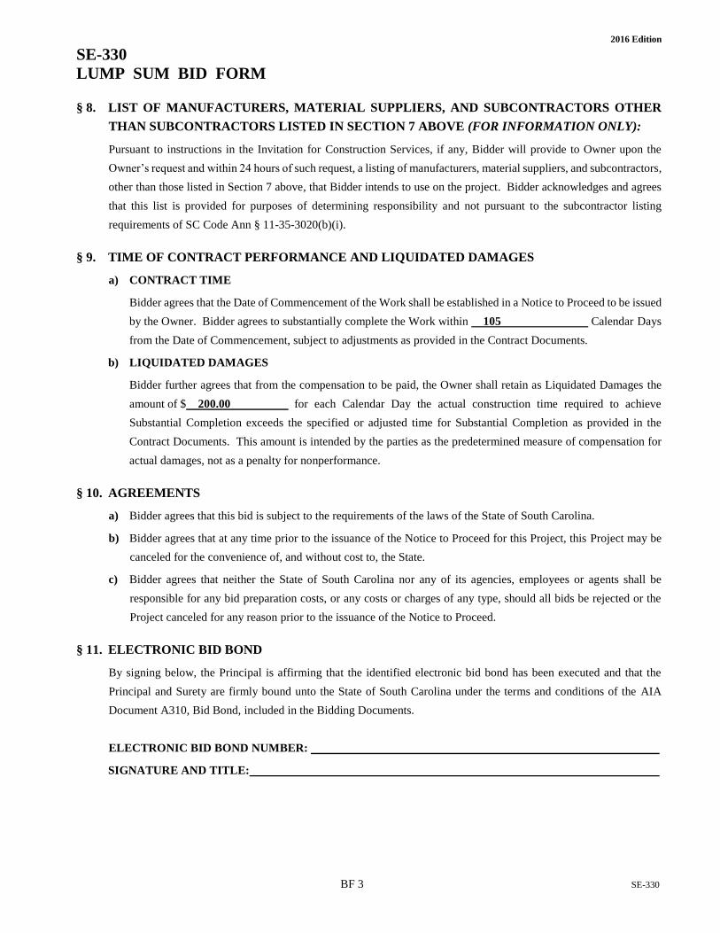
§ 9. TIME OF CONTRACT PERFORMANCE AND LIQUIDATED DAMAGES
a) CONTRACT TIME
Bidder agrees that the Date of Commencement of the Work shall be established in a Notice to Proceed to be issued
by the Owner. Bidder agrees to substantially complete the Work within 105 Calendar Days
from the Date of Commencement, subject to adjustments as provided in the Contract Documents.
b) LIQUIDATED DAMAGES
Bidder further agrees that from the compensation to be paid, the Owner shall retain as Liquidated Damages the
amount of $ 200.00 for each Calendar Day the actual construction time required to achieve
Substantial Completion exceeds the specified or adjusted time for Substantial Completion as provided in the
Contract Documents. This amount is intended by the parties as the predetermined measure of compensation for
actual damages, not as a penalty for nonperformance.
§ 10. AGREEMENTS
a) Bidder agrees that this bid is subject to the requirements of the laws of the State of South Carolina.
b) Bidder agrees that at any time prior to the issuance of the Notice to Proceed for this Project, this Project may be
canceled for the convenience of, and without cost to, the State.
c) Bidder agrees that neither the State of South Carolina nor any of its agencies, employees or agents shall be
responsible for any bid preparation costs, or any costs or charges of any type, should all bids be rejected or the
Project canceled for any reason prior to the issuance of the Notice to Proceed.
§ 11. ELECTRONIC BID BOND
By signing below, the Principal is affirming that the identified electronic bid bond has been executed and that the
Principal and Surety are firmly bound unto the State of South Carolina under the terms and conditions of the AIA
Document A310, Bid Bond, included in the Bidding Documents.
ELECTRONIC BID BOND NUMBER:
SIGNATURE AND TITLE:

BF 4 SE-330
2016 Edition
SE-330
LUMP SUM BID FORM
CONTRACTOR'S CLASSIFICATIONS AND SUBCLASSIFICATIONS WITH LIMITATION
SC Contractor's License Number(s):
Classification(s) & Limits:
Subclassification(s) & Limits:
By signing this Bid, the person signing reaffirms all representation and certification made by both
the person signing and the Bidder, including without limitation, those appearing in Article 2 of the
Instructions to Bidders, is expressly incorporated by reference.
BIDDER’S LEGAL NAME:
ADDRESS:
TELEPHONE:
EMAIL:
SIGNATURE: DATE:
PRINT NAME:
TITLE:


Project Name: Hodge Center Cooling Tower Replacement Project Number: H34-9544
CONTRACTOR’S ONE YEAR GUARANTEE STATE OF ___________________________________________________________________________ COUNTY OF _________________________________________________________________________ WE__________________________________________________________________________ as General Contractor on the above-named project, do hereby guarantee that all work executed under the requirements of the Contract Documents shall be free from defects due to faulty materials and /or workmanship for a period of one (1) year from date of acceptance of the work by the Owner and/or Architect/Engineer; and hereby agree to remedy defects due to faulty materials and/or workmanship, and pay for any damage resulting wherefrom, at no cost to the Owner, provided; however, that the following are excluded from this guarantee; Defects or failures resulting from abuse by Owner. Damage caused by fire, tornado, hail, hurricane, acts of God, wars, riots, or civil commotion. _________________________________________ [Name of Contracting Firm]
*By________________________________ Title_______________________________
*Must be executed by an office of the Contracting Firm. SWORN TO before me this __________ day of ___________, 2____ (seal) _________________________State My commission expires __________________

1 of 2 SE-355
2016 Edition
SE-355
PERFORMANCE BOND
KNOW ALL MEN BY THESE PRESENTS, that (Insert full name or legal title and address of Contractor)
Name:
Address:
hereinafter referred to as “Contractor”, and (Insert full name and address of principal place of business of Surety)
Name:
Address:
hereinafter called the “surety”, are jointly and severally held and firmly bound unto (Insert full name and address of Agency)
Name: University of South Carolina
Address: 743 Greene Street
Columbia, SC 29208
hereinafter referred to as “Agency”, or its successors or assigns, the sum of ($ ), being the
sum of the Bond to which payment to be well and truly made, the Contractor and Surety bind themselves, their heirs,
executors, administrators, successors and assigns, jointly and severally, firmly by these presents.
WHEREAS, Contractor has by written agreement dated entered into a contract with Agency to construct
State Project Name: Hodge Center Cooling Tower Replacement
State Project Number: H34-9544
Brief Description of Awarded Work, as found on the SE-330 or SE-332, Bid Form: Replace existing cooling tower with
new cooling tower at same location including mechanical, electrical, and structural work.
in accordance with Drawings and Specifications prepared by (Insert full name and address of A/E)
Name: Peritus Engineers and Associates, Inc.
Address: P. O. Box 16598
Greenville, SC 29606
which agreement is by reference made a part hereof, and is hereinafter referred to as the Contract.
IN WITNESS WHEREOF, Surety and Contractor, intending to be legally bound hereby, subject to the terms stated herein,
do each cause this Performance Bond to be duly executed on its behalf by its authorized officer, agent or representative.
DATED this day of , 2 BOND NUMBER (shall be no earlier than Date of Contract)
CONTRACTOR SURETY
By:
(Seal)
By:
(Seal)
Print Name:
Print Name:
Print Title:
Print Title: (Attach Power of Attorney)
Witness:
Witness:
(Additional Signatures, if any, appear on attached page)

2 of 2 SE-355
2016 Edition
SE-355
PERFORMANCE BOND
NOW, THEREFORE, THE CONDITION OF THIS OBLIGATION IS SUCH THAT:
1. The Contractor and the Surety, jointly and severally, bind
themselves, their heirs, executors, administrators, successors and
assigns to the Agency for the full and faithful performance of the
contract, which is incorporated herein by reference.
2. If the Contractor performs the contract, the Surety and the
Contractor have no obligation under this Bond, except to
participate in conferences as provided in paragraph 3.1.
3. The Surety's obligation under this Bond shall arise after:
3.1 The Agency has notified the Contractor and the Surety at the
address described in paragraph 10 below, that the Agency is
considering declaring a Contractor Default and has
requested and attempted to arrange a conference with the
Contractor and the Surety to be held not later than 15 days
after receipt of such notice to discuss methods of performing
the Contract. If the Agency, the Contractor and the Surety
agree, the Contractor shall be allowed a reasonable time to
perform the Contract, but such an agreement shall not waive
the Agency's right, if any, subsequently to declare a
Contractor Default; or
3.2 The Agency has declared a Contractor Default and formally
terminated the Contractor's right to complete the Contract.
4. The Surety shall, within 15 days after receipt of notice of the
Agency's declaration of a Contractor Default, and at the Surety's
sole expense, take one of the following actions:
4.1 Arrange for the Contractor, with consent of the Agency, to
perform and complete the Contract; or
4.2 Undertake to perform and complete the Contract itself,
through its agents or through independent contractors; or
4.3 Obtain bids or negotiated proposals from qualified
contractors acceptable to the Agency for a contract for
performance and completion of the Contract, arrange for a
contract to be prepared for execution by the Agency and the
contractor selected with the Agency's concurrence, to be
secured with performance and payment bonds executed by a
qualified surety equivalent to the Bonds issued on the
Contract, and pay to the Agency the amount of damages as
described in paragraph 7 in excess of the Balance of the
Contract Sum incurred by the Agency resulting from the
Contractor Default; or
4.4 Waive its right to perform and complete, arrange for
completion, or obtain a new contractor, and:
4.4.1 After investigation, determine the amount for which
it may be liable to the Agency and, within 60 days of waiving
its rights under this paragraph, tender payment thereof to the
Agency; or
4.4.2 Deny liability in whole or in part and notify the
Agency, citing the reasons therefore.
5. Provided Surety has proceeded under paragraphs 4.1, 4.2, or
4.3, the Agency shall pay the Balance of the Contract Sum to
either:
5.1 Surety in accordance with the terms of the Contract; or
5.2 Another contractor selected pursuant to paragraph 4.3 to
perform the Contract.
5.3 The balance of the Contract Sum due either the Surety or
another contractor shall be reduced by the amount of
damages as described in paragraph 7.
6. If the Surety does not proceed as provided in paragraph 4
with reasonable promptness, the Surety shall be deemed to be in
default on this Bond 15 days after receipt of written notice from
the Agency to the Surety demanding that the Surety perform its
obligations under this Bond, and the Agency shall be entitled to
enforce any remedy available to the Agency.
6.1 If the Surety proceeds as provided in paragraph 4.4 and the
Agency refuses the payment tendered or the Surety has denied
liability, in whole or in part, then without further notice the
Agency shall be entitled to enforce any remedy available to
the Agency.
6.2 Any dispute, suit, action or proceeding arising out of or
relating to this Bond shall be governed by the Dispute
Resolution process defined in the Contract Documents and the
laws of the State of South Carolina.
7. After the Agency has terminated the Contractor's right to
complete the Contract, and if the Surety elects to act under
paragraph 4.1, 4.2, or 4.3 above, then the responsibilities of the
Surety to the Agency shall be those of the Contractor under the
Contract, and the responsibilities of the Agency to the Surety shall
those of the Agency under the Contract. To a limit of the amount
of this Bond, but subject to commitment by the Agency of the
Balance of the Contract Sum to mitigation of costs and damages
on the Contract, the Surety is obligated to the Agency without
duplication for:
7.1 The responsibilities of the Contractor for correction of
defective Work and completion of the Contract; and
7.2 Additional legal, design professional and delay costs resulting
from the Contractor's Default, and resulting from the actions
or failure to act of the Surety under paragraph 4; and
7.3 Damages awarded pursuant to the Dispute Resolution
Provisions of the Contract. Surety may join in any Dispute
Resolution proceeding brought under the Contract and shall
be bound by the results thereof; and
7.4 Liquidated Damages, or if no Liquidated Damages are
specified in the Contract, actual damages caused by delayed
performance or non-performance of the Contractor.
8. The Surety shall not be liable to the Agency or others for
obligations of the Contractor that are unrelated to the Contract, and
the Balance of the Contract Sum shall not be reduced or set-off on
account of any such unrelated obligations. No right of action shall
accrue on this Bond to any person or entity other than the Agency
or its heirs, executors, administrators, or successors.
9. The Surety hereby waives notice of any change, including
changes of time, to the contract or to related subcontracts, purchase
orders and other obligations.
10. Notice to the Surety, the Agency or the Contractor shall be
mailed or delivered to the address shown on the signature page.
11. Definitions
11.1 Balance of the Contract Sum: The total amount payable by the
Agency to the Contractor under the Contract after all proper
adjustments have been made, including allowance to the
Contractor of any amounts to be received by the Agency in
settlement of insurance or other Claims for damages to which
the Contractor si entitled, reduced by all valid and proper
payments made to or on behalf of the Contractor under the
Contract.
11.2 Contractor Default: Failure of the Contractor, which has
neither been remedied nor waived, to perform the Contract or
otherwise to comply with the terms of the Contract.

1 of 2 SE-357
2016 Edition
SE-357
LABOR & MATERIAL PAYMENT BOND
KNOW ALL MEN BY THESE PRESENTS, that (Insert full name or legal title and address of Contractor)
Name:
Address:
hereinafter referred to as “Contractor”, and (Insert full name and address of principal place of business of Surety)
Name:
Address:
hereinafter called the “surety”, are jointly and severally held and firmly bound unto (Insert full name and address of Agency)
Name: University of South Carolina
Address: 743 Greene Street
Columbia, SC 29208
hereinafter referred to as “Agency”, or its successors or assigns, the sum of ($ ), being the
sum of the Bond to which payment to be well and truly made, the Contractor and Surety bind themselves, their heirs,
executors, administrators, successors and assigns, jointly and severally, firmly by these presents.
WHEREAS, Contractor has by written agreement dated entered into a contract with Agency to construct
State Project Name: Hodge Center Cooling Tower Replacement
State Project Number: H34-9544
Brief Description of Awarded Work, as found on the SE-330 or SE-332, Bid Form: Replace existing cooling tower with
new cooling tower at same location including mechanical, electrical, and structural work.
in accordance with Drawings and Specifications prepared by (Insert full name and address of A/E)
Name: Peritus Engineers & Associates, Inc.
Address: P. O. Box 16598
Greenville, SC 29606
which agreement is by reference made a part hereof, and is hereinafter referred to as the Contract.
IN WITNESS WHEREOF, Surety and Contractor, intending to be legally bound hereby, subject to the terms stated herein,
do each cause this Labor & Material Payment Bond to be duly executed on its behalf by its authorized officer, agent or
representative.
DATED this day of , 2 BOND NUMBER (shall be no earlier than Date of Contract)
CONTRACTOR SURETY
By:
(Seal)
By:
(Seal)
Print Name:
Print Name:
Print Title:
Print Title: (Attach Power of Attorney)
Witness:
Witness:
(Additional Signatures, if any, appear on attached page)

2 of 2 SE-357
2016 Edition
SE-357
LABOR & MATERIAL PAYMENT BOND
NOW, THEREFORE, THE CONDITION OF THIS OBLIGATION IS SUCH THAT:
1. The Contractor and the Surety, jointly and severally, bind
themselves, their heirs, executors, administrators, successors and
assigns to the Agency to pay for all labor, materials and equipment
required for use in the performance of the Contract, which is
incorporated herein by reference.
2. With respect to the Agency, this obligation shall be null and
void if the Contractor:
2.1 Promptly makes payment, directly or indirectly, for all sums
due Claimants; and
2.2 Defends, indemnifies and holds harmless the Agency from all
claims, demands, liens or suits by any person or entity who
furnished labor, materials or equipment for use in the
performance of the Contract.
3. With respect to Claimants, this obligation shall be null and
void if the Contractor promptly makes payment, directly or
indirectly, for all sums due.
4. With respect to Claimants, and subject to the provisions of
Title 29, Chapter 5 and the provisions of §11-35-3030(2)(c) of the
SC Code of Laws, as amended, the Surety’s obligation under this
Bond shall arise as follows:
4.1 Every person who has furnished labor, material or rental
equipment to the Contractor or its subcontractors for the work
specified in the Contract, and who has not been paid in full
therefore before the expiration of a period of ninety (90) days
after the date on which the last of the labor was done or
performed by him or material or rental equipment was
furnished or supplied by him for which such claim is made,
shall have the right to sue on the payment bond for the
amount, or the balance thereof, unpaid at the time of
institution of such suit and to prosecute such action for the
sum or sums justly due him.
4.2 A remote claimant shall have a right of action on the payment
bond upon giving written notice by certified or registered
mail to the Contractor within ninety (90) days from the date
on which such person did or performed the last of the labor
or furnished or supplied the last of the material or rental
equipment upon which such claim is made.
4.3 Every suit instituted upon a payment bond shall be brought in
a court of competent jurisdiction for the county or circuit in
which the construction contract was to be performed, but no
such suit shall be commenced after the expiration of o ne year
after the day on which the last of the labor was performed or
material or rental equipment was supplied by the person
bringing suit.
5. When the Claimant has satisfied the conditions of paragraph 4,
the Surety shall promptly and at the Surety’s expense take the
following actions:
5.1 Send an answer to the Claimant, with a copy to the Agency,
within sixty (60) days after receipt of the claim, stating the
amounts that are undisputed and the basis for challenging any
amounts that are disputed.
5.2 Pay or arrange for payment of any undisputed amounts.
5.3 The Surety’s failure to discharge its obligations under this
paragraph 5 shall not be deemed to constitute a waiver of
defenses the Surety or Contractor may have or acquire as to
a claim. However, if the Surety fails to discharge its
obligations under this paragraph 5, the Surety shall indemnify
the Claimant for the reasonable attorney’s fees the Claimant
incurs to recover any sums found to be due and owing to the
Claimant.
6. Amounts owed by the Agency to the Contractor under the
Contract shall be used for the performance of the Contract and to
satisfy claims, if any, under any Performance Bond. By the
Contractor furnishing and the Agency accepting this Bond, they
agree that all funds earned by the contractor in the performance of
the Contract are dedicated to satisfy obligations of the Contractor
and the Surety under this Bond, subject to the Agency’s prior right
to use the funds for the completion of the Work.
7. The Surety shall not be liable to the Agency, Claimants or
others for obligations of the Contractor that are unrelated to the
Contract. The Agency shall not be liable for payment of any costs
or expenses of any claimant under this bond, and shall have under
this Bond no obligations to make payments to, give notices on
behalf of, or otherwise have obligations to Claimants under this
Bond.
8. The Surety hereby waives notice of any change, including
changes of time, to the Contract or to related Subcontracts,
purchase orders and other obligations.
9. Notice to the Surety, the Agency or the Contractor shall be
mailed or delivered to the addresses shown on the signature page.
Actual receipt of notice by Surety, the Agency or the contractor,
however accomplished, shall be sufficient compliance as of the
date received at the address shown on the signature page.
10. By the Contractor furnishing and the Agency accepting this
Bond, they agree that this Bond has been furnished to comply with
the statutory requirements of the South Carolina Code of Laws, as
amended, and further, that any provision in this Bond conflicting
with said statutory requirements shall be deemed deleted herefrom
and provisions conforming to such statutory or other legal
requirement shall be deemed incorporated herein. The intent is
that this Bond shall be construed as a statutory Bond and not as a
common law bond.
11. Upon request of any person or entity appearing to be a
potential beneficiary of this bond, the Contractor shall promptly
furnish a copy of this Bond or shall permit a copy to be made.
12. Any dispute, suit, action or proceeding arising out of or
relating to this Bond shall be governed by the laws of the State of
South Carolina.
13. DEFINITIONS
13.1 Claimant: An individual or entity having a direct contract
with the Contractor or with a Subcontractor of the
Contractor to furnish labor, materials, or equipment for use
in the performance of the Contract. The intent of this Bond
shall be to include without limitation in the terms “labor,
materials or equipment” that part of water, gas, power, light,
heat, oil, gasoline, telephone service or rental equipment
used in the Contract, architectural and engineering services
required for performance of the Work of the Contractor and
the Contractor’s Subcontractors, and all other items for
which a mechanic’s lien might otherwise be asserted.
13.2 Remote Claimant: A person having a direct contractual
relationship with a subcontractor of the Contractor or
subcontractor, but no contractual relationship expressed or
implied with the Contractor.
13.3 Contract: The agreement between the Agency and the
Contractor identified on the signature page, including all
Contract Documents and changes thereto.

SE-380
2016 Edition
SE-380 CHANGE ORDER NO.:
CHANGE ORDER TO CONSTRUCTION CONTRACT
AGENCY: University of South Carolina PROJECT NAME: Hodge Center Cooling Tower Replacement PROJECT NUMBER: H34-9544
CONTRACTOR: CONTRACT DATE: This Contract is changed as follows: (Insert description of change in space provided below)
ADJUSTMENTS IN THE CONTRACT SUM:
1. Original Contract Sum: $
2. Change in Contract Sum by previously approved Change Orders:
3. Contract Sum prior to this Change Order $ 0.00
4. Amount of this Change Order:
5. New Contract Sum, including this Change Order: $ 0.00
ADJUSTMENTS IN THE CONTRACT TIME: 1. Original Substantial Completion Date:
2. Sum of previously approved increases and decreases in Days: Days
3. Change in Days for this Change Order Days
4. New Substantial Completion Date:
CONTRACTOR ACCEPTANCE: BY: Date:
(Signature of Representative) Print Name:
A/E RECOMMENDATION FOR ACCEPTANCE:
BY: Date:
(Signature of Representative) Print Name:
AGENCY ACCEPTANCE AND CERTIFICATION:
BY: Date:
(Signature of Representative) Print Name:
Change is within Agency Construction Contract Change Order Certification of: $ Yes No
Office of the State Engineer Authorization for change exceeding Agency Construction Contract Change Order Certification:
AUTHORIZED BY: DATE: (OSE Project Manager)
SUBMIT THE FOLLOWING TO OSE 1. SE-380, fully completed and signed by the Contractor, A/E and Agency; 2. Detailed back-up information from the Contractor/Subcontractor(s) that justifies the costs and schedule changes shown. 3. If any item exceeds Agency certification, OSE will authorize the SE-380 and return to Agency.

HODGE CENTER COOLING TOWER REPLACEMENT Division 1 State Project No. H34-9544 Spartanburg, South Carolina
ADMINISTRATIVE REQUIREMENTS 01300 - 1
SECTION 01300 – ADMINISTRATIVE REQUIREMENTS PART 1 - GENERAL 1.1 SECTION INCLUDES
A. Preconstruction conference.
B. Progress meetings. PART 2 PRODUCTS – NOT USED PART 3 EXECUTION 3.1 PRECONSTRUCTION CONFERENCE
A. Engineer will schedule a meeting after Notice of Award. 1. Meeting to take place no later than 15 days following the execution of the
Agreement.
B. Attendance Required:
1. Owner.
2. Engineer.
3. Contractor.
C. Agenda: Agenda to be prepared by Contractor and distributed to all invited attendees,
to include:
1. Project organizational structure and chain of command. 2. Duties and expectations of the Owner, Engineer, and Contractor. 3. Submission of executed bonds and insurance certificates. 4. Project scope of work. 5. Construction schedule. 6. Distribution of Contract Documents. 7. Contract disputes, mediation, partnering, and resolution. 8. Submission of list of Subcontractors, list of Projects, schedule of values, and
progress schedule. 9. Designation of personnel representing the parties, including Owner, Contractor

HODGE CENTER COOLING TOWER REPLACEMENT Division 1 State Project No. H34-9544 Spartanburg, South Carolina
ADMINISTRATIVE REQUIREMENTS 01300 - 2
and Engineer. 10. Work schedule, normal working hours, and normal work week. Also to include
required notice for scheduling overtime, outages, and interruptions. 11. Safety procedures. 12. Temporary and permanent utilities. 13. Security, keys, fencing, site access, and limited access to certain areas. 14. Designated parking and delivery areas. 15. Designated storage areas, bonded storage, and security. 16. Designated toilets, break areas, vending areas, and smoking areas. 17. Daily cleanup, trash removal, dumpsters, and trash areas. 18. Procedures and processing of field decisions, submittals, RFIs, substitutions,
applications for payments, proposal requests, Change Orders, and Contract closeout procedures.
19. Procedures and responsibilities for testing and inspecting, required permits, and
licenses. 20. Demolition items to be salvaged for Owner, notification, and storage area. 21. Scheduling. 22. Preparation of Record Documents, and Operating and Maintenance Manuals. 23. Instruction and training of Owner’s maintenance personnel. 24. Warranties, manufacturer startup, prior to substantial completion. 25. Final completion inspection and punch list. 26. One-year warranty inspection (Engineer to inspect 10 months after substantial
completion). 27. Contractor corrections for items found during the warranty inspection.
D. Contractor shall record minutes and distribute copies within three days after meeting to
participants, with copies to Engineer, Owner, participants, and those affected by decisions made.
3.02 PROGRESS MEETINGS
HODGE CENTER COOLING TOWER REPLACEMENT Division 1 State Project No. H34-9544 Spartanburg, South Carolina
ADMINISTRATIVE REQUIREMENTS 01300 - 3
A. Contractor shall schedule and administer meetings throughout progress of the Work at maximum bi-monthly intervals.
B. Contractor shall make arrangements for meetings, prepare agenda with copies for
participants, and preside at meetings. C. Attendance Required: Contractor’s project manager, job superintendent, major
Subcontractors and suppliers, Owner, Engineer as appropriate to agenda topics for each meeting.
D. Agenda:
1. Review of Work progress.
2. Field observations, problems, and decisions.
3. Identification of problems that impede, or will impede, planned progress.
4. Review of submittals schedule and status of submittals.
5. Maintenance of progress schedule.
6. Corrective measures to regain projected schedule.
7. Planned progress during succeeding work period.
8. Maintenance of quality and work standards.
9. Effect of proposed changes on progress schedule and coordination.
10. Other business relating to Work.
E. Contractor shall record minutes and distribute copies within three days after meeting to
participants, with copies to Engineer, Owner, participants, and those affected by decisions made. Engineer shall review a draft copy of the minutes prior to distribution.
3.03 PROJECT RECORD DOCUMENTS
A. Record Prints: Maintain one set of blue- or black-line white prints of the Contract Drawings and Shop Drawings. Mark prints to show actual installation where installation varies from that shown originally.
1. Cross reference changes on Contract Drawings and Shop Drawings, noting
construction change directive numbers, change order numbers and similar identification where applicable.
2. Identify and date each Record Drawing; include the designation "PROJECT
RECORD DRAWING" in a prominent location.
3. Organize into unbound sets. Place record prints in durable tube-type drawing
containers with end caps. Mark end cap of each container with identification. If container does not include a complete set, identify Drawings included.

HODGE CENTER COOLING TOWER REPLACEMENT Division 1 State Project No. H34-9544 Spartanburg, South Carolina
ADMINISTRATIVE REQUIREMENTS 01300 - 4
B. Record Specifications: Mark Specifications to indicate actual product installation where installation varies from that indicated in Specifications, addenda, and contract modifications. Note related Change Orders, Record Product Data, and Record Drawings where applicable.
C. Record Product Data: Mark Product Data to indicate the actual project installation
where installation varies substantially from that indicated in Product Data submittal. Note related Change Orders, Record Specifications, and Record Drawings where applicable.
END OF SECTION 01300
HODGE CENTER COOLING TOWER REPLACEMENT Division 1 State Project No. H34-9544 Spartanburg, South Carolina
CONSTRUCTION PROGRESS SCHEDULE 01320 - 1
SECTION 01320 – CONSTRUCTION PROGRESS SCHEDULE PART 1 - GENERAL 1.01 SECTION INCLUDES
A. Preliminary schedule.
B. Construction progress schedule, bar chart type. 1.02 SUBMITTALS
A. Within 10 days after date of Agreement, submit four copies of preliminary schedule.
B. If preliminary schedule required revision after review, submit four copies of revised schedule within 10 days.
C. Within 20 days after review of preliminary schedule, submit four (4) copies of draft of
proposed complete schedule for review.
D. Within 10 days after joint review, submit four copies of complete schedule. Submittal and approval of project Schedule is a condition precedent to the Payment of progress payments. Therefore, no construction work will be permitted and no progress payments will be made until project schedule has been approved by the Owner’s Representative.
E. Submit updated schedule with each Application for Payment.
F. Daily Construction Report: Submit one (1) bound copy with project record documents
at end of construction.
G. Filed Condition Reports: Submit four (4) copies at time of discovery of differing conditions.
1.03 COORDINATION
A. Coordinate preparation and processing of schedules and reports with performance of construction activities and with scheduling and reporting of separate contractors.
B. Coordinate Contractor’s Construction Schedule with the Schedule of Values, list of
subcontracts, Submittals Schedule, progress reports, payment requests, and other required schedules and reports.
1. Secure time commitments for performing critical elements of the Work from
parties involved. 2. Coordinate each construction activity in the network with other activities and
schedule them in proper sequence. 1.04 SCHEDULE FORMAT

HODGE CENTER COOLING TOWER REPLACEMENT Division 1 State Project No. H34-9544 Spartanburg, South Carolina
CONSTRUCTION PROGRESS SCHEDULE 01320 - 2
A. Listings: In chronological order according to the start date for each activity. Identify
each activity with the applicable specification section number.
B. Sheet Size: Multiples of 8-1/2 x 11 inches.
PART 2 PRODUCTS 2.01 PRELIMINARY SCHEDULE
A. Define planned operations for the first 60 days of Work with a general outline for remainder of Work.
B. Prepare in the form of a horizontal bar chart.
2.02 SUBMITTALS SCHEDULE
A. Submit a schedule of submittals, arranged in chronological order by dates required by construction schedule. Include time required for review, resubmitted, ordering, manufacturing, fabrication, and delivery when establishing dates.
1. Coordinate Submittals Schedule with list of subcontractors, the Schedule of
Values, and Contractor’s Construction Schedule.
B. Submit 4 copies of schedule. Arrange the following information in a tabular format.
1. Scheduled date for first submittal.
2. Specification Section number and title.
3. Submittal category (action or informational.)
4. Name of subcontractor.
5. Description of the Work covered.
6. Scheduled date for Engineer’s final release or approval.
2.03 CONTRACTOR’S CONSTRUCTION SCHEDULE
A. Show complete sequence of construction by activity, with dates for beginning and completion of each element of construction, in the form of a horizontal bar chart.
B. Identify each item by specification section number.
C. Identify work of separate stages and other logically grouped activities.
D. Show accumulated percentage of completion of each item, and total percentage of
Work completed, as of the first day of each month.
E. Coordinate content with Schedule of Values.

HODGE CENTER COOLING TOWER REPLACEMENT Division 1 State Project No. H34-9544 Spartanburg, South Carolina
CONSTRUCTION PROGRESS SCHEDULE 01320 - 3
F. Provide legend for symbols and abbreviations used.
G. Include a separate bar for each major portion of Work or operation.
H. Identify the first work day of each week. 2.04 DAILY CONSTRUCTION REPORTS
A. Prepare a daily construction report recording the following information concerning events at the project site:
1. List of subcontractors at Project site.
2. Equipment at Project site.
3. Material deliveries.
4. High and low temperatures and weather conditions.
5. Accidents.
6. Stoppages, delays, shortages, and losses.
7. Meter readings and similar recordings.
8. Orders and requests of authorities having jurisdiction.
9. Services connected and disconnected.
10. Equipment or system tests or startups.
2.05 FIELD CONDITION REPORTS
A. Immediately upon the discovery of a difference between field conditions and the Contract Documents, prepare a detailed report. Submit with a request for information. Include a detailed description of the differing conditions, together with recommendations for changing the Contract Documents.
PART 3 EXECUTION 3.01 REVIEW AND EVALUATION OF SCHEDULE
A. Participate in joint review and of schedule with Engineer at each submittal.
B. Evaluate project status to determine work behind schedule and work ahead of schedule.
C. After review, revise as necessary as result of review, and resubmit within 10 days.
3.02 UPDATING SCHEDULE
A. Main schedules to record actual start and finish dates of completed activities.

HODGE CENTER COOLING TOWER REPLACEMENT Division 1 State Project No. H34-9544 Spartanburg, South Carolina
CONSTRUCTION PROGRESS SCHEDULE 01320 - 4
B. Indicate progress of each activity to date of revision, with projected completion date of each activity.
C. Identify activities modified since previous submittal, major changes in Work, and other
identifiable changes.
D. Indicate changes required to maintain Date of Substantial Completion.
E. Submit reports required to support recommended changes.
F. Update schedule monthly and submit with each Application for Payment. 3.03 DISTRIBUTION OF SCHEDULE
A. Distribute copies of updated schedules to Contractor’s project site file, to Subcontractors, suppliers, Engineer, Owner, and other concerned parties with a need-to-know scheduling responsibility.
B. Instruct recipients to promptly report, in writing, problems anticipated by projections
shown in schedules.
C. Post copies in Project meeting rooms and in temporary field offices.
D. When revisions are made, distribute updated schedules to the same parties and post in the same locations.
END OF SECTION 01320

HODGE CENTER COOLING TOWER REPLACEMENT Division 1 State Project No. H34-9544 Spartanburg, South Carolina
SUBMITTAL PROCEDURES 01330 - 1
SECTION 01330 – SUBMITTAL PROCEDURES PART 1 - GENERAL 1.01 SUBMITTAL SCHEDULE
A. Include a submittal register listing all anticipated submittals, shop drawings, product data, and samples as defined in the Contract Documents and also include certificates, test data, schedules, and other submitted data required to demonstrate compliance with the Contract Documents.
1.02 SUBMITTAL DESCRIPTIONS
A. Submit four copies of each of the following unless otherwise specified.
1. SD-01 Manufacturer’s Catalog Data
a. Data composed of catalog cuts, brochures, circulars, specifications and product data, and printed information in sufficient details and scope to verify compliance with requirements of the Contract Documents. Reviews and submittals shall be as specified for shop drawings. Clearly mark product data to identify the applicable products or models proposed for use. Clearly identify items where options or modifications are required by the Contract Documents.
2. SD-02 Drawings/Procedures/Schedules
a. Shop Drawings: Submit shop drawings in the form of one reproducible
print and three blue line or black line prints. Drawings size shall not exceed 24 inches by 30 inches. After review, the Engineer will return the reproducible print with any applicable notations and an appropriate stamp. If corrections are to be made, the original drawings shall be revised and a new reproducible and three prints submitted, and repeated until so approved. Upon approval, a reproducible marked as such will be returned to the Contractor. A minimum clear space, 4 inches high x 6 inches long, shall be left on the reproducible print above or to the left of the title block or application of the approval stamp. The contractor shall be responsible for the prints required for the work, and these prints shall be from the final reproducible bearing the final stamp of the Engineer.
3. SD-03 Certificates
a. Certificates signed by responsible officials of a manufacturer of a project,
system, or material attesting that the product, system, or material meet specified requirements. Submit certificates certifying the method of installation or quality of installation at the completion of the work. The submittal must be dated after the award of this contract, name the project and list the specific requirements, which it is intended to address.
4. SD-04 Samples

HODGE CENTER COOLING TOWER REPLACEMENT Division 1 State Project No. H34-9544 Spartanburg, South Carolina
SUBMITTAL PROCEDURES 01330 - 2
a. Samples, including both fabricated and un-fabricated physical examples
of materials, products, and units of work as complete units or as portions of units of work.
b. Submit samples of sufficient size and quantity to illustrate clearly the
functional characteristics of the product with integrally related parts and attachment devices. Approved samples are the standard by which the finished work will be evaluated. Furnish one sample for each required submittal unless otherwise specified in the technical specifications. In general, deliver samples to the office of the Engineer unless the Engineer requests delivery to the Owner or the building site. Full-size usable samples will be returned to the Contractor and approved samples may be used as part of the work unless they are specified otherwise in the technical specifications.
5. SD-05 Warranty Forms
a. Prior to installation, submit warranty forms complete in every respect,
except for authorized signature(s) and date of commencement. 1.03 CONTRACTOR PREPARATION
A. Certification:
1. Contractor submittals shall be reviewed by the Contractor prior to submittal to the Engineer and shall include the following certification:
a. “I hereby certify that the material(s), equipment, and/or article(s) shown
and marked in this submittal and proposed to be incorporated into the Work is (are) in strict conformance with the Contract Documents, can be installed in the allocated spaces, and comprises(s) no variation thereto, unless specifically noted otherwise.”
2. Contractor Review and Coordination: Before submitting a show drawing or
related material to the Engineer, the Contractor shall:
a. Review each such submission for conformance with the Contractor’s means, method techniques, sequences and operations of construction, and safety precautions and programs incidental thereto, all of which are the sole responsibility of the Contractor.
b. Review and coordinate each such submission with other related or
affected work. c. Approve each such submission before submitting same; and d. Provide the required Contractor’s certification as specified in Paragraph
A1a Certification, above.

HODGE CENTER COOLING TOWER REPLACEMENT Division 1 State Project No. H34-9544 Spartanburg, South Carolina
SUBMITTAL PROCEDURES 01330 - 3
3. By approving a submittal, the Contractor thereby warrants and represents that he has determined and verified applicable field measurements, field construction criteria, materials, catalog numbers and similar data, and has checked and coordinated the submittal with the requirements of the Work and for conformance with the Contract Documents. Submittals submitted without the required certification and coordination will be returned to the Contractor without review. Delays in construction because of late submission or re-submission of required submittals shall be the sole responsibility of the Contractor.
4. Deviations: If a submittal deviates from the drawings and project manual
because of standard shop practice, substitutions (approved in accordance with the General Conditions as amended), or any other reason advise Engineer via a separate written instrument. Otherwise, the Contractor will not be relieved of the responsibility for executing the Work in accordance with the Contract Documents even though such submittals may have been approved.
5. Extent of Submittals: Submit only submittals required by the Contract
Documents. The Engineer reserves the right to refrain from reviewing other submittals.
a. Do not include items from more than one specification section per
submittal. b. Contractor may require additional documentation from subcontractors
or suppliers for his own use at no additional cost to the Owner. Such documentation shall not be submitted for review without prior written consent from the Engineer.
c. Submit only complete specifications sections for review; no partial
submittals will be accepted. Incomplete specifications sections will be returned without review by the Engineer.
1.04 FORM OF SUBMITTAL
A. Submit letter of transmittal in duplicate with each submission listing the contents of the submission and identifying each items by reference to specifications section or drawing. Clearly label shop drawings with the name of the project and other necessary information. Bound product data and other similar material that cannot be so labeled conveniently in suitable covers bearing the identifying data. Distribution of submittals by Engineer will be as specified in Paragraph “Owner’s Representative Procedures.” Additional copies, as required, shall be marked by the Contractor for his use after submittals have been approved.
1.05 TIME FOR REVIEW
A. The Contractor shall allow a minimum of ten (10) consecutive working days (i.e. Monday through Friday, excluding holidays, and measured from the date of receipt of the Contractor’s submittal) for the Engineer’s review of each submittal. The same minimum timeframe shall be allowed for at least one (1) re-submittal of each such

HODGE CENTER COOLING TOWER REPLACEMENT Division 1 State Project No. H34-9544 Spartanburg, South Carolina
SUBMITTAL PROCEDURES 01330 - 4
submittal. 1.06 RESUBMISSION
A. Change or correct submittals as required by the Engineer and resubmit until approved. Indicate any changes which have been made other than those requested by the Engineer.
B. Use the same transmittal procedure as outlined above.
1.07 OWNER’S REPRESENTATIVE’S PROCEDURES
A. Owner’s Representative’s Review: Submittals will be reviewed with reasonable promptness.
B. Submittals shall be returned with the Engineer’s submittal stamp with designations for
approval, rejection, correction, or resubmittal. 1.08 DISTRIBUTION OF SUBMITTALS
A. Approved Shop Drawings, product data, manufacturer’s literature, and certificates, will be distributed by the Engineer as follows:
1. Reproducible shop drawing and one copy of product data and manufacturer’s
literature to the Contractor. 2. One copy of all submittals to the Owner’s Representative.
B. Changes After Approval
1. Make no change in a submittal marked “Reviewed” or “Furnish as Corrected”
without obtaining the prior written consent of the Engineer. If such written consent is obtained, revise the submittal to show fully the altered parts of the work and resubmit according to the procedures specified herein. State on resubmittal that the work shown supersedes and voids identified parts of the same work previously shown. Give full identification on the drawings previously approved by the Engineer and the date of such action.
1.09 PROCEEDING WITHOUT APPROVAL
A. No submittal may be used in the shop or on the work, except in accordance with the foregoing paragraphs. Proceeding with any construction and ordering or fabricating materials before all relevant drawings have been “Reviewed” or marked “Furnish as Corrected” shall be done at the Contractor’s sole risk.
PART 2 PRODUCTS (NOT USED) PART 3 EXECUTION (NOT USED) END OF SECTION 01330

HODGE CENTER COOLING TOWER REPLACEMENT Division 1 State Project No. H34-9544 Spartanburg, South Carolina
SECURITY PROCEDURES 01355 - 1
SECTION 01355 – SECURITY PROCEDURES PART 1 - GENERAL 1.01 SECTION INCLUDES
A. Security measures including formal security program, entry control, personnel identification, and miscellaneous restrictions.
1.02 SECURITY PROGRAM
A. Protect Work, existing premises and Owner’s operations from theft, vandalism and unauthorized entry.
B. Initiate program in coordination with Owner’s existing security system at project
mobilization.
C. Maintain program throughout construction period until Owner acceptance precludes the need for Contractor security.
1.03 ENTRY CONTROL
A. Restrict entrance of persons and vehicles into Project site and existing facilities.
B. Allow entrance only to authorized persons with proper identification.
C. Maintain log of workers and visitors, make available to Owner on request.
D. Owner will control entrance of persons and vehicles related to Owner’s operations.
E. Coordinate access of Owner’s personnel to site in coordination with Owner’s security forces.
F. Secure all construction equipment, machinery and vehicles, park and store only within
fenced area, and render inoperable during non-work hours. Contractor is responsible to insure that no construction materials, tools, equipment, machinery, or vehicles can be used for unauthorized entry or other damage or interference to activities and security of existing facilities adjacent to and in the vicinity of construction site.
1.04 PERSONNEL IDENTIFICATION
A. Provide identification badge to each person authorized to enter premises.
B. Badge to include: Personal photograph, name assigned number, expiration date and
employer.
C. Maintain a list of accredited persons; submit copy to Owner on request.
D. Require return of badges at expiration of their employment on the work.
PART 2 PRODUCTS & PART 3 EXECUTION (NOT USED) END OF SECTION 01355

HODGE CENTER COOLING TOWER REPLACEMENT Division 1 State Project No. H34-9544 Spartanburg, South Carolina
QUALITY REQUIREMENTS 01400 - 1
SECTION 01400 – QUALITY REQUIREMENTS PART 1 - GENERAL 1.01. SECTION INCLUDES
A. Qualifications. B. Control of Installation.
C. Mock-ups.
D. Tolerances.
E. Manufacturer’s field services.
F. Defect Assessment.
1.02 QUALITY ASSURANCE
A. Installation of new cooling towers shall be carefully scheduled with owner to minimize impacts to normal building operations that use chilled water. Shutdown and demolition of existing cooling tower systems shall be coordinated and scheduled with owner so that shutdown duration may be minimized.
1.03 QUALIFICATIONS
A. General: Qualifications paragraphs in this Article establish the minimum qualification levels required; individual Specification Sections specify additional requirements.
B. Installer Qualifications: A firm or individual experienced in installing, erecting, or
assembling work similar in material, design, and extent to that indicated for this Project, whose work has resulted in construction with a record of successful in-service performance.
C. Manufacturer Qualifications: A firm experienced in manufacturing products or systems
similar to those indicated for this Project and with a record of successful in-service performance, as well as sufficient production capacity to produce required units.
D. Fabricator Qualifications: A firm experienced in manufacturing products similar to those
indicated for this Project and with a record of successful in-service performance, as well as sufficient production capacity to product required units.
E. Professional Engineer Qualifications: A professional engineer who is legally qualified to
practice in jurisdiction where Project is located and who is experienced in providing engineering services of the kind indicated. Engineering services are defined as those performed for installations of the system, assembly, or products that are similar to those indicated for this project in material, design, and extent.
HODGE CENTER COOLING TOWER REPLACEMENT Division 1 State Project No. H34-9544 Spartanburg, South Carolina
QUALITY REQUIREMENTS 01400 - 2
F. Specialists: Certain sections of the Specifications require that specific construction activities shall be performed by entities who are recognized experts in those operations. Specialists shall satisfy qualification requirements indicated and shall be engaged for the activities indicated.
1. Requirements for specialists shall not supersede building codes and regulations
governing the Work.
G. Factory-Authorized Service Representative Qualifications: An authorized representative of manufacturer who is trained and approved by manufacturer to inspect installation of manufacturer’s products that are similar in material, design, and extent to those indicated for this Project.
PART 2 PRODUCTS (NOT USED) PART 3 EXECUTION 3.01 CONTROL OF INSTALLATION
A. Monitor quality control over suppliers, manufacturers, products, services, site conditions, and workmanship, to produce Work of specified quality.
B. Comply with manufacturers’ instructions, including each step in sequence.
C. Should manufacturer’s instructions conflict with Contract Documents, request
clarification from Engineer before proceeding?
D. Comply with specified standards as minimum quality for the Work except where more stringent tolerances, codes or specified requirements indicate higher standards or more precise workmanship. If compliance with two or more standards is specified and the standards establish different or conflicting requirements for minimum quantities or quality levels, comply with the most stringent requirement. Refer uncertainties and requirements that are different, but apparently equal, to Engineer for a decision before proceeding.
E. Have Work performed by persons qualified to produce required and specified quality.
F. Verify that field measurements are as indicated on shop drawings or as instructed by
the manufacturer.
G. Secure products in place with positive anchorage devices designed and sized to withstand stresses, vibration, physical distortion, and disfigurement.
3.02 MANUFACTURERS’ FIELD SERVICES
A. When specified in individual specification sections, require material or product suppliers or manufacturers to provide qualified staff personnel to observe site conditions, conditions of surfaces and installation, quality of workmanship, start-up of equipment, test, adjust and balance of equipment as applicable, and to initiate instructions when necessary.

HODGE CENTER COOLING TOWER REPLACEMENT Division 1 State Project No. H34-9544 Spartanburg, South Carolina
QUALITY REQUIREMENTS 01400 - 3
B. Report observations and site decisions or instructions given to applicators or installers that are supplemental or contrary to manufacturers’ written instructions.
3.03 DEFECT ASSESSMENT
A. Replace Work or portions of the Work not conforming to specified requirements.
B. If, in the opinion of Engineer, it is not practical to remove and replace the Work, Engineer will direct an appropriate remedy or adjust payment.
END OF SECTION 01400

HODGE CENTER COOLING TOWER REPLACEMENT Division 1 State Project No. H34-9544 Spartanburg, South Carolina
TEMPORARY FACILITIES AND CONTROLS 01500 - 1
SECTION 01500 – TEMPORARY FACILITIES AND CONTROLS PART 1 - GENERAL 1.01 SECTION INCLUDES
A. Equipment. B. Temporary sanitary facilities.
C. Temporary Controls. Barriers, enclosures, and fencing.
D. Environmental Procedures and Controls.
E. Temporary facilities installation, operation, and maintenance.
1.02 QUALITY ASSURANCE
A. Installation of new cooling towers shall be carefully scheduled with owner to minimize impacts to normal building operations that use chilled water. Shutdown and demolition of existing cooling tower systems shall be coordinated and scheduled with owner so that shutdown duration may be minimized.
1.03 SUBMITTALS
A. See Section 01330 for submittal procedures.
B. Site Plan: Show temporary facilities, utility hookups, staging areas, and parking areas for construction personnel.
1.04 EQUIPMENT
A. Self-Contained Toilet Units: Single-occupant units of chemical, aerated recirculation or combustion type; vented; fully enclosed with glass-fiber-reinforced polyester shell or similar non-absorbent material.
B. Drinking-Water Fixtures: Drinking–water fountains, containerized, tap-dispensed,
bottled-water drinking-water units, including paper cup supply.
1.05 TEMPORARY SANITARY FACILITIES
A. Provide and maintain required temporary toilets, wash facilities, and drinking water for construction personnel. Comply with authorities having jurisdiction for type, number, location, operation, and maintenance of fixtures and facilities.
B. Maintain daily in clean and sanitary condition.
1.06 BARRIERS

HODGE CENTER COOLING TOWER REPLACEMENT Division 1 State Project No. H34-9544 Spartanburg, South Carolina
TEMPORARY FACILITIES AND CONTROLS 01500 - 2
A. Provide barriers to prevent unauthorized entry to construction areas, to allow for
Owner’s use of site and to protect existing facilities and adjacent properties from damage from construction operations and demolition.
B. Protect non-owned vehicular traffic, stored materials, site, and structures from damage.
C. Provide fencing/barriers around work area to ensure the safety of workers on the
project. Areas of construction must be properly enclosed and secured at all times. 1.06 EXTERIOR ENCLOSURES
A. Before construction operations begin, Contractor will install chain-link enclosure fence with lockable entrance gates at staging and storage areas. Contractor to provide padlocks.
1. Maintain security by limiting the number of keys and restricting distribution to
authorized personnel. Provide Owner with one set of keys. 2. Contractor will remove enclosure fence at end of construction. 3. Contractor is responsible for filling in post holes and reseeding grassed areas as
required. B. Refer to construction drawings for designated location for required exterior enclosure
area. PART 2 PRODUCTS (NOT USED) PART 3 EXECUTION 3.01 ENVIRONMENTAL PROCEDURES AND CONTROLS
A. Environmental Protection: Provide protection, operate temporary facilities, and conduct construction in ways and by methods that comply with environmental regulations and that minimize possible air, waterway, and subsoil contamination or pollution or other undesirable effects.
B. Pollution Controls.
1. Use water mist, temporary enclosures, and other suitable methods to limit the
spread of dirt and dust generated by construction operations. Comply with governing environmental protection regulations.
a. Do not create hazardous or objectionable conditions, such as ice, flooding, and
pollution when using water.
2. Remove and transport debris in a manner that will prevent spillage on adjacent surfaces and areas.
3. Clean adjacent buildings and improvements of dust, dirt and debris caused by

HODGE CENTER COOLING TOWER REPLACEMENT Division 1 State Project No. H34-9544 Spartanburg, South Carolina
TEMPORARY FACILITIES AND CONTROLS 01500 - 3
Construction operations. Return adjacent areas to condition existing before start of demolition.
3.02 TEMPORARY FACILITIES INSTALLATION, OPERATION AND MAINTENANCE, AND
REMOVAL
A. Supervision: Enforce strict discipline in use of temporary facilities. To minimize waste and abuse, limit availability of temporary facilities to essential and intended uses.
B. Installation: Install temporary sanitary facilities, barriers, and exterior enclosures at time
of Project mobilization.
C. Maintenance and Operation:
1. Clean site daily.
2. Temporary sanitary facilities to be cleaned daily.
D. Termination and Removal: Remove each temporary facility when need for its service
has ended, or not later than Substantial Completion.
END OF SECTION 01500
HODGE CENTER COOLING TOWER REPLACEMENT Division 1 State Project No. H34-9544 Spartanburg, South Carolina
VEHICULAR ACCESS AND PARKING 01550- 1
SECTION 01550 – VEHICULAR ACCESS AND PARKING PART 1 - GENERAL 1.01. SECTION INCLUDES
A. Access roads. B. Parking.
C. Existing pavements and parking areas.
D. Permanent pavements and parking facilities.
E. Construction parking controls.
F. Traffic signs and signals.
G. Maintenance.
H. Removal, repair.
I. Mud from site vehicles.
PART 2 PRODUCTS (NOT USED) PART 3 EXECUTION 3.01 ACCESS ROADS
A. Use of designated existing on-site streets and driveways for construction traffic is permitted.
B. Tracked vehicles not allowed on paved areas.
C. Provide unimpeded access for emergency vehicles. Maintain 20 foot width driveways
with turning space between and around combustible materials.
D. Provide and maintain access to fire hydrants free of obstructions. 3.02 PARKING
A. Use of designated areas of existing parking facilities by construction personnel is permitted.
B. Do not allow heavy vehicles or construction equipment in parking areas.
C. Arrange with Owner for temporary parking areas to accommodate use of construction
personnel.
D. When site space is not adequate, provide additional off-site parking.
E. Locate as approved by Owner. 3.03 CONSTRUCTION PARKING CONTROL

HODGE CENTER COOLING TOWER REPLACEMENT Division 1 State Project No. H34-9544 Spartanburg, South Carolina
VEHICULAR ACCESS AND PARKING 01550- 2
A. Control vehicular parking to prevent interference with public traffic and parking, access by emergency vehicles, and Owner’s operations.
B. Monitor parking of construction personnel’s vehicles in existing facilities. Maintain
vehicular access to and through parking areas.
C. Prevent parking on or adjacent to access roads or in non-designated areas. 3.04 HAUL ROUTES
A. Consult with authority having jurisdiction, establish public thoroughfares to be used for haul routes and site access.
B. Confine construction traffic to designated haul routes.
C. Provide traffic control at critical areas of haul routes to regulate traffic, to minimize
interference with public traffic. 3.05 TRAFFIC SIGNS AND SIGNALS
A. At approaches to site and on site, install at crossroads, detours, parking areas, and elsewhere as needed to direct construction and affected public traffic.
3.06 MAINTENANCE
A. Maintain traffic and parking areas in a sound condition free of excavated material, construction equipment, products, mud, snow, and ice.
B. Maintain existing paved areas used for construction; promptly repair breaks, potholes,
low areas, standing water, and other deficiencies, to maintain paving and drainage in original, or specified, condition.
3.07 REMOVAL, REPAIR
A. Repair existing facilities damaged by use, to original condition.
B Remove equipment and devices when no longer required. B. Repair damage caused by installation.
3.08 MUD FROM SITE VEHICLES
A. Provide means of removing mud from vehicle wheels before entering streets. END OF SECTION 01550

HODGE CENTER COOLING TOWER REPLACEMENT Division 1 State Project No. H34-9544 Spartanburg, South Carolina
CONSTRUCTION WASTE MANAGEMENT AND DISPOSAL 01741- 1
SECTION 01741 – CONSTRUCTION WASTE MANAGEMENT AND DISPOSAL PART 1 - GENERAL 1.01 SECTION INCLUDES
A. Waste management requirements and implementation.
1.02 WASTE MANAGEMENT REQUIREMENTS
A. Employ processes that ensure the generation of as little waste as possible due to error, poor planning, breakage, mishandling, contamination, or other factors.
B. Minimize trash/waste disposal in landfills; reuse, salvage, or recycle as much waste as
economically feasible.
C. Methods of trash/waste disposal that are not acceptable are:
1. Burning on the project site.
2. Burying on the project site.
3. Dumping or burying on other property, public or private.
4. Other illegal dumping or burying.
D. Regulatory Requirements: Contractor is responsible for knowing and complying with
regulatory requirements, including but not limited to Federal, State and local requirements, pertaining to legal disposal of all construction and demolition waste materials.
PART 2 PRODUCTS (NOT USED) PART 3 EXECUTION 3.01 WASTE MANAGEMENT IMPLEMENTATION
A. Instruction: Provide on-site instruction of appropriate separation, handling, and recycling, salvage, reuse, and return methods to be used by all parties at the appropriate stages of the project.
B. Meetings: Discuss trash/waste management goals and issues at project meetings.
1. Pre-bid meeting.
2. Pre-construction meeting.
3. Regular job-site meetings.
C. Facilities: provide specific facilities for separation and storage of materials for recycling, salvage, reuse, return, and trash disposal, for use by all constructors and installers.

HODGE CENTER COOLING TOWER REPLACEMENT Division 1 State Project No. H34-9544 Spartanburg, South Carolina
CONSTRUCTION WASTE MANAGEMENT AND DISPOSAL 01741- 2
1. As a minimum, provide:
a. Separate area for storage of materials to be reused on-site, such as wood cut-
offs for blocking.
b. Separate dumpsters for each category of recyclable. c. Recycling bins at worker lunch area.
2. Provide containers as required. 3. Provide adequate space for pick-up and delivery and convenience to
subcontractors. 4. Keep recycling and trash/waste bin areas heat and clean and clearly marked in
order to avoid contamination of materials.
D. Hazardous Wastes: Separate, store, and dispose of hazardous wastes according to applicable regulations.
E. Recycling: Separate, store, protect, and handle at the site identified recyclable waste
products in order to prevent contamination of materials and to maximize recyclability of identified materials. Arrange for timely pickups from the site or deliveries to recycling facility in order to prevent contamination of recyclable materials.
F. Reuse of Materials ON-Site: Set aside, sort, and protect separated products in
preparation for reuse.
G. Salvage: Set aside, sort, and protect products to be salvaged for reuse off-site.
H. Clean site daily to remove trash and debris. END OF SECTION 01741

HODGE CENTER COOLING TOWER REPLACEMENT Division 15 State Project No. H34-9544 Spartanburg, South Carolina
MECHANICAL GENERAL PROVISIONS 15000 - 1
SECTION 15000 - MECHANICAL GENERAL PROVISIONS PART 1 - GENERAL 1.1 RELATED DOCUMENTS:
A. Drawings and General Provisions of Contract, including General and Supplementary Conditions and Division-1 Specification sections, apply to work of this section.
B. This section is a Division-15 Basic Materials and Methods Section, and a part of
each Division-15 section making reference to mechanical related work specified herein.
1.2 SUMMARY OF MECHANICAL WORK:
A. Drawings: Refer to the HVAC-Series drawings for graphic representations, schedules and notations showing mechanical work.
B. Specifications: Refer to Division-15 sections for the primary technical
specifications of mechanical work.
C. General Outline: The facilities and systems of the mechanical work can be described (but not by way of limitation) as follows: New Cooling Tower and associated piping, including controls, and testing, adjusting, and balancing of systems. Also the demolition of existing cooling towers, piping, and associated structure is to be included in the project.
1.3 COORDINATION OF MECHANICAL WORK:
A. GENERAL: Refer to the Division 1 sections for general coordination requirements applicable to the entire work. It is recognized that the contract documents are diagrammatic in showing certain physical relationships which must be established within the mechanical work, and in its interface with other work including utilities and electrical work, and that such establishment is the exclusive responsibility of the Contractor.
1.4 QUALITY ASSURANCE, STANDARDS AND SYMBOLS:
A. General: Refer to Division 1 sections for general administrative/procedural requirements related to compliance with codes and standards. Specifically, for the mechanical work (in addition to standards specified in individual work sections), the following standards are imposed, as applicable to the work in each instance:
1. International Building Code (IBC, 2015 Edition) 2. International Energy Conservation Code (IECC), 2009 Edition 3. International Mechanical Code (IMC), 2015 Edition 4. South Carolina Department of Health & Environmental Control 5. National Electrical Code, NFPA 70

HODGE CENTER COOLING TOWER REPLACEMENT Division 15 State Project No. H34-9544 Spartanburg, South Carolina
MECHANICAL GENERAL PROVISIONS 15000 - 2
B. Secure and pay for all costs related to permits, governmental fees, license, cost
necessary for the proper execution and completion of the work, which are applicable at the time the bids are received.
1.5 ELECTRICAL CODE LABELING REQUIREMENTS:
A. All electrically powered equipment shall be UL labeled or labeled by similar testing agency or shall meet International Building Code for Alternate Material and Methods in lieu of labels.
1.6 SUBMITTALS:
A. General: Refer to Division 1 sections for general requirements concerning work-related submittals (refer to other Division 1 sections for administrative submittals). For mechanical work, the following quantities are required for each category of submittal (in addition to the quantities specified in Division 1), unless otherwise indicated in individual work sections (quantity does not include copies required by governing authorities, or by Contractor for its own purposes):
6 sets, including 3 for maintenance manuals.
B. Engineer will review Contractor's shop drawings and related submittals with
respect to the ability of the detailed work, when complete, to be a properly functioning integral element of the overall system designed by the Engineer.
C. Before submitting a shop drawing or any related material to the Engineer, the
Contractor and his Subcontractor (if any) shall: review each such submission for conformance with the means, methods, dimensional space limitations, techniques, sequences, and operations of construction, and safety precautions and programs incidental thereto, all of which are the sole responsibility of the Contractor; approve each such submission before submitting it; and so stamp each such submission before submitting it. The Engineer shall assume that no shop drawing or related submittal comprises a variation unless the Contractor and his Subcontractor (if any) advises the Engineer otherwise via a written instrument which is acknowledged by the Engineer in writing. The shop drawings and related material (if any) called for are indicated below. In the event that the Engineer will require more than ten (10) working days to perform review, the Engineer shall so notify the Contractor.
D. The Engineer shall return shop drawings and related materials with comments
provided that each submission has been called for and is stamped by the Contractor and his Subcontractor (if any) as indicated above. The Engineer shall return without comment material not called for or which has not been approved by the Contractor and his Subcontractor (if any).
E. Product Data Required:
1. Cooling Tower 2. Piping

HODGE CENTER COOLING TOWER REPLACEMENT Division 15 State Project No. H34-9544 Spartanburg, South Carolina
MECHANICAL GENERAL PROVISIONS 15000 - 3
3. Piping Accessories 4. Piping Insulation, including heat tracing 5. Controls 6. Valves 7. Variable Frequency Drive (VFD)
F. Certifications: 3 copies.
G. Test Reports: 3 copies.
H. Warranties (Guarantees): 6 copies, including 3 for maintenance manuals.
I. Maintenance Manuals: 3 complete sets with individual sets of this data bound in
10-1/2 x 11-1/2 loose-leaf 3-ring binders, 1-1/2", 2" or 3" ring size, with rigid permanent vinyl covered back and front. Separators with index tabs and loose-leaf sheet protectors shall be provided. One set shall have all sheets individually encased in clear plastic document protectors. Each set shall include the following data:
1. Valve Directory indicating valve number, size, manufacturer, location,
function, and normal position. Valve tag numbers shall be as specified.
2. Mechanical Equipment: Show the following information for all mechanical equipment:
a. Nameplate designation. b. Manufacturer's nameplate data. c. Location of equipment. d. Area served. e. Complete parts drawing and list. f. Manufacturer's operating instructions. g. Manufacturer's maintenance instructions. h. Manufacturer's installation instructions. i. Nearest supplier for parts and replacements with telephone
number. j. Nearest service organization for equipment with telephone
number.
3. Control Data:
a. Control diagrams and wiring diagrams where applicable. b. Description of control system. c. Catalog data, maintenance and calibration instruction for all
components. d. Control supplier and address. e. Control installer and address.
4. Maintenance Instruction: A typewritten form of instructions for
maintenance of the systems, in itemized form and with time schedule for maintenance work, shall be furnished. The instructions shall list each item

HODGE CENTER COOLING TOWER REPLACEMENT Division 15 State Project No. H34-9544 Spartanburg, South Carolina
MECHANICAL GENERAL PROVISIONS 15000 - 4
of mechanical equipment requiring inspection, lubrication or service and describe the performance of such maintenance. The list shall include the type of bearings for each piece of equipment, the type of and frequency of lubrication required. The operating personnel shall be instructed in the care of the system in accordance with the typewritten instructions.
1.7 PRODUCTS, MECHANICAL WORK:
A. GENERAL: Refer to Division 1 sections for general requirements on products, materials and equipment.
PARTS 2 AND 3 - PRODUCTS AND EXECUTION 2.1 ELECTRICAL PROVISIONS OF MECHANICAL WORK:
A. WIRING:
1. All control wiring (120V and less) to be complete to all motorized equipment, and control devices listed in this specification and shown on the mechanical drawings, shall be done under Division 15. The Contractor shall refer to Electrical plans and specifications to determine the source of electrical energy for the various control circuits. All wiring shall be in conduit, shall conform to Division 16 of this specification, all local codes, the National Electrical Code, and shall be installed by an approved licensed Electrical Contractor. Wiring diagrams indicating wire sizes and conduit runs for all electrical work that is required to be installed under this contract shall be submitted to the Engineer for prior approval before work is begun. Upon completion of the work, the wiring diagrams shall be revised to incorporate any additions or corrections and two copies of the "as installed" diagrams shall be furnished to the owner and one to the Engineer on reproducible paper or electronic media.
B. MOTORS:
1. Motors for equipment shall be of approved manufacture and of electrical,
speed, and torque characteristics shown on the drawings. Motors 3/4 h.p. and above shall be wound for 3 phase, 60 cycle current; and 1/2 h.p. and under, 1 phase, 60 cycle current. Single phase motors shall be furnished with built-in overload and under-voltage protection. Nameplates for all motors shall be stamped for the current characteristics indicated on the drawings.
2. The use of shaded pole motors above 1/20 h.p. is prohibited. 3. Motors shall be premium high efficiency type (90% plus), E + 3 and shall
have capacity of not less than the horsepower noted on the drawings, and shall not exceed their full rated load when the driven equipment is operating at specified capacity under the most severe conditions likely to be encountered.
4. Motors shall have continuous-duty classification based on 40 deg. C. ambient temperature of reference.
5. All motors 1/2 h.p. and larger shall have grease lubricated ball bearings.

HODGE CENTER COOLING TOWER REPLACEMENT Division 15 State Project No. H34-9544 Spartanburg, South Carolina
MECHANICAL GENERAL PROVISIONS 15000 - 5
6. All motors, regardless of horsepower, shall have over-current protection installed either as an integral part of the motor, or within the motor controlling device in accordance with the National Electrical Code.
C. MOTOR STARTERS:
1. Motor starters not integral to supplied equipment shall be furnished where
required and installed by the Electrical Contractor. 2.2 FOUNDATIONS AND MISCELLANEOUS STEEL SUPPORTS:
A. Foundations: Refer to structural drawings. All concrete foundations anchor forms, or pads that may be necessary and required for the installation of equipment, or support of piping, specified under this contract, shall be furnished and installed by others under the building construction project. This contractor to provide anchor bolts for the equipment foundations. New cooling towers shall have poured concrete piers and steel structural support (see Structural Drawings).
B. Miscellaneous Steel Supports: All supporting steel grillage, steel angles,
channels, pipe or structural steel stands, and anchoring devices that may be required to adequately and rigidly support either piping, insulation, or equipment installed under this contract, shall be provided and installed. Refer to Structural Drawings for piping supports.
2.3 MECHANICAL SYSTEM IDENTIFICATION:
A. Piping System: All piping installed under this division of the specifications shall be identified as follows.
B. Method of Marking: Colored stencil letters that designate the material being
handled, shall be applied at not more than 40 foot intervals on straight pipe runs, at each terminal piece of equipment, adjacent to valves, and where pipe passes through walls and floors. Piping shall be marked at all the equipment connections.
C. Identification: Lettering shall be stenciled in block letters, size as scheduled
below. Letters on covered (insulated) pipe shall be stenciled on covering. On uncovered pipe, painted bands shall be wide enough (See Table 1) to accommodate required letters. Lettering shall be positioned so that it can be easily read by a man standing on the floor. Lettering on parallel groups of lines shall be neatly lined up. Surfaces of piping or insulation finished in dark colored shall be lettered in white; and that finished in light colors shall be lettered in black.
1. All lines also shall be marked with arrows indicating the direction of flow.
TABLE I
Letter Size Outside Diameter of Size of

HODGE CENTER COOLING TOWER REPLACEMENT Division 15 State Project No. H34-9544 Spartanburg, South Carolina
MECHANICAL GENERAL PROVISIONS 15000 - 6
Pipe or Converting (Inches) Letter (Inches) 1/2 to 1-1/4 1/2 1-1/2 to 2 3/4 2-1/2 to 12 1-1/4 All dimensions are given in inches. 2.4 ACCESSIBILITY:
A. No valves, controls, unions, etc., shall be placed in any pipe line at a location that will be inaccessible after the system is completed.
2.5 PAINTING MECHANICAL WORK:
A. General: No painting shall be done under this division other than the sizing of the insulation jackets. Color stenciling of piping for identification, and touching up paint that is chipped or scratched from mechanical equipment supplied; and 2 coats of black rust preventative on all exposed support metal and hangers mounted outdoors and in mechanical rooms.
2.6 CLEANING, TESTING, ADJUSTMENTS AND INSPECTIONS:
A. Shall be accomplished in accordance with the following instructions and requirements. Provide temporary fill and drainage lines, wherever required, and connect them to the piping systems for these procedures and, finally, upon completion disconnect and remove these temporary lines.
B. Cleaning and Oiling: All piping systems shall be thoroughly cleaned of grease,
iron cuttings, welding slag, loose scale and other refuse. Should any pipe, valves, strainers, and other specialties, and equipment be stopped up by refuse, disconnect, clean and reconnect such pipe, equipment and material. All strainer baskets shall be removed, cleaned and replaced.
C. Exterior surfaces of piping, materials, or equipment that is to be painted or
insulated shall be cleaned to remove lint, grease and oil.
D. All components of the mechanical systems shall be cleaned on outside of dust, trash, paint and masonry dropping, and left in first class condition. All motor and equipment bearings shall be lubricated as recommended by the individual manufacturer and oil reservoir shall be left full.
2.7 EQUIPMENT START-UP:
A. The contractor to responsible for all equipment start-up. All equipment to be started by the contractor or under the contractor's direct supervision.
B. The entire temperature control system shall be adjusted and placed in operation
by the Controls Contractor. 2.8 BALANCING:

HODGE CENTER COOLING TOWER REPLACEMENT Division 15 State Project No. H34-9544 Spartanburg, South Carolina
MECHANICAL GENERAL PROVISIONS 15000 - 7
A. The work of water balancing and flow testing is to be coordinated by this
Contractor. Testing and balancing shall begin after the contractor informs the Owner that construction has progressed to the point of allowing testing and balancing. The HVAC contractor shall assist the balancing sub-contractor during the balancing phases of work to expedite the work. Assistance to include, but not limited to, operation of system, installing valves that may have been omitted, etc.
2.9 MECHANICAL WORK CLOSEOUT:
A. General: Refer to the Division 1 sections for general closeout requirements. Maintain a daily log of operational data on mechanical equipment and systems through the closeout period.
B. Closeout Equipment/Systems Operations: Sequence operations properly so that
work of project will not be damaged or endangered. Coordinate with seasonal requirements. Operate each item of equipment and each system in a test run of appropriate duration (with the Engineer present, and with the Owner's operating personnel present), to demonstrate sustained, satisfactory performance. Adjust and correct operations as required for proper performance. Clean and lubricate each system, and replace excessively worn parts and similar expendable items of the work.
C. Operating Instructions: Conduct a one (1) day walk-through instruction seminar
for the Owner's personnel to be involved in the continued operation and maintenance of mechanical equipment and systems. Explain the identification system, operational diagrams, emergency and alarm provisions, sequencing requirements, seasonal provisions, security, safety, efficiency and similar features of the systems.
D. Turn-Over of Operations: At the time of substantial completion, turn over the
prime responsibility for operation of the mechanical equipment and systems to the Owner’s operating personnel. However, until the time of final acceptance, provide one full- time operating engineer, who is completely familiar with the work, to consult with and continue training the Owner's personnel.
END OF SECTION 15000

HODGE CENTER COOLING TOWER REPLACEMENT Division 15 State Project No. H34-9544 Spartanburg, South Carolina
DEMOLITION 15001 - 1
SECTION 15001 - DEMOLITION PART 1 - GENERAL 1.1 RELATED DOCUMENTS:
A. Drawings and General Provisions of Contract, including General and Supplementary Conditions and Division - 1 Specification sections, apply to work of this section.
1.2.1 DESCRIPTION OF WORK:
A. The extent of demolition work shall be performed in general, but not limited to, removal of existing as follows: a. Remove existing cooling tower and accessories, cooling tower piping, water
piping to point shown, and piping accessories, etc.
B. Demolition includes removal and disposal of demolished materials. 1.3 SUBMITTALS:
A. Schedule: Submit proposed methods and operations of demolition to Engineer for review prior to start of work. Include in schedule coordination for systems shutdown, connection/changeover to newly installed system, and demolition of existing system.
1.4 JOB CONDITIONS:
A. Occupancy: Building will be in operation during work and can be shut down at a scheduled shut-down time, to perform new system tie-in to existing. It is expected that chiller #2 and cooling tower #2 shall be in operation during construction of this project.
B. Condition of existing systems: The Owner assumes no responsibility for actual
condition of items to be demolished. Conditions existing at time of inspection for bidding purposes will be maintained by Owner in so far as practicable.
C. Protection: Ensure safe passage of persons in and around areas of demolition.
Conduct operations to prevent injury to building, structure, other facilities, and persons.
D. Damages: Promptly repair damages caused to facilities by demolition operations at
no cost to Owner.
E. Utility Services: Maintain existing utilities, keep in service, and protect against damage during demolition operations.
PART 2 - PRODUCTS
HODGE CENTER COOLING TOWER REPLACEMENT Division 15 State Project No. H34-9544 Spartanburg, South Carolina
DEMOLITION 15001 - 2
Not applicable. PART 3 - EXECUTION 3.1 DEMOLITION:
A. Demolition of all parts to be removed shall be done in a safe, orderly fashion taking care to avoid damage to parts which are to be left in place. All debris shall be removed from the premises as it is generated and shall not be allowed to accumulate. In the event the Contractor has any question about items to be removed, the Contractor to ask the Engineer.
3.2 DISPOSAL OF DEMOLISHED MATERIALS:
A. General: Remove from site debris, rubbish, and other materials resulting from demolition operations.
B. Removal: Transport demolished materials removed from premise and legally
dispose of off-site. END OF SECTION 15001

HODGE CENTER COOLING TOWER REPLACEMENT Division 15 State Project No. H34-9544 Spartanburg, South Carolina
PIPE, TUBE AND FITTINGS 15060 - 1
SECTION 15060 - PIPE, TUBE AND FITTINGS PART 1 - GENERAL 1.1 RELATED DOCUMENTS:
A. Drawings and General Provisions of Contract, including General and Supplementary Conditions and Division - 1 specification sections, apply to work of this section.
B. This section is a Division-15 Basic Materials and Methods Section, and a part of
each Division-15 section making reference to pipe, tube and fittings specified herein. 1.2 DESCRIPTION:
A. Extent of pipe, tube, and fittings required by this section is indicated on drawings and/or specified in other Division-15 sections.
1.3 QUALITY ASSURANCE:
A. Manufacturers: Firms regularly engaged in the manufacture of piping products of types and sizes required, and which have been in satisfactory use for not less than 5 years in similar service.
B. Welding: Qualify welding procedures, welders and operators in accordance with
ANSI B 31.1, paragraph 127.5, for shop and project site welding of piping work.
C. Certify welding of piping work using the Standard Procedure Specifications by, and welders tested under supervision of, the National Certified Pipe Welding Bureau.
D. Welding Certifications, Piping Work: Submit reports as required for welding
certifications. 1.4 PRODUCT HANDLING:
A. Provide factory-applied plastic end-caps on each length of pipe and tube. Maintain end-caps through shipping, storage and handling as required to prevent pipe-end damage and eliminate dirt and moisture from inside of pipe and tube.
B. Where possible, store pipe and tube inside and protected from weather. Where
necessary to store outside, elevate well above grade and enclose with durable, waterproof wrapping.
C. Protect flanges and fittings from moisture and dirt by inside storage and enclosure,
or by packaging with durable, waterproof wrapping. PART 2 - PRODUCTS 2.1 PIPING MATERIALS:
A. General: Provide pipe and tube of the type, joint type, grade, size and weight (wall
HODGE CENTER COOLING TOWER REPLACEMENT Division 15 State Project No. H34-9544 Spartanburg, South Carolina
PIPE, TUBE AND FITTINGS 15060 - 2
thickness or Class) indicated for each service. Where type, grade or class is not indicated, provide proper selection as determined by Installer for installation requirements, and comply with governing regulations and industry standards.
B. Steel Pipe:
1. Black Steel Pipe Schedule 40: ASTM A 53, A 106 or A 120; except comply
with ASTM A 53 or A 106 where close coiling or bending is required. 2. Galvanized Steel Pipe Schedule 40: ASTM A 53 or A 120; except comply
with ASTM A 53 where close coiling or bending is required.
C. Copper Tube: ASTM B88, Type (L) hard-drawn temper; except as otherwise indicated.
2.2 PIPE/TUBE FITTINGS:
A. General: Provide factory-fabricated fittings of the type, materials, grade, class and pressure rating indicated for each service and pipe size. Provide sizes and types matching pipe, tube, valve or equipment connection in each case. Where not otherwise indicated, comply with governing regulations and industry standards for selections, and with pipe manufacturer's recommendations where applicable.
B. Fittings for Steel Pipe:
1. Steel Pipe Nipples: shall be of the same material and finish as the lines in
which they are installed. No all-thread (close) nipples will be permitted. 2. Joints in steel pipe shall be in accordance with the following:
a. Screwed Piping: Joints shall be made with a non-hardening pipe joint compound applied to the male thread only.
b. Welded Piping - Joints shall be made as specified within. c. Gasket Material for flanged joints shall be similar in all respects to
Style D, 150 lb. series, as produced by Flexitallic Gasket Company. Comparable material by Garlock, or Akron Metallic Gasket Company will be acceptable.
D. Fittings for Black Steel Pipe shall be:
1. Screwed Fittings - 150 lb. gray cast iron conforming to ANSI NO. B16.4. 2. Flanged Fittings - 150 Lb. gray cast iron conforming to ASTM NO. A181. 3. Unions: - 300 lb. malleable iron ground joints with brass-to-iron seats
conforming to ANSI No. B16.3. 4. Flanges - 150 lb. steel welding neck with raised face conforming to ASTM
No. A181 except for matching flanges required at equipment and valves. 5. Welding Fittings, including elbows, reducing ells, caps, straight tees,
reducing tees, straight and reducing laterals and reducers shall be "standard weight", Grade B fittings, meeting ASTM A234, as produced by Crane, Tube-Turns, Taylor Forge or equal. Furnish long radius 90 degree elbows. Complete ASTM specification information shall be stamped on each fitting.
6. Standard Weight Weldolets or Threadolets may be used in lieu of welding tees only where the branch line is at least two pipe sizes smaller than main.

HODGE CENTER COOLING TOWER REPLACEMENT Division 15 State Project No. H34-9544 Spartanburg, South Carolina
PIPE, TUBE AND FITTINGS 15060 - 3
Under no circumstances will it be permissible for one pipe line to be welded directly into another, regardless of size.
7. Manufacture. Welding fittings and flanges which have been machined, remarked, painted, or otherwise produced domestically from non-domestic forgings will not be acceptable. Fittings and flanges shall have the manufacturer's trademark permanently identified in accordance with MSS SP-25.
E. Fittings for Galvanized Steel Pipe shall be:
1. Screwed Fittings - 150 lb. galvanized malleable iron banded type conforming
to ANSI No. B16.3. 2. Unions - 150 lb. galvanized malleable iron, ground joint with brass-to-iron
seat conforming to ANSI NO. B16.3.
D. Fittings for Copper Tube:
1. Cast-Bronze Solder-Joint Fittings: ANSI B16.18. 2. Wrought-Copper/Bronze Solder-Joint Fittings: ANSI B16.22. 3. Copper-Tube Unions: Provide standard products recommended by the
manufacturer for use in the service indicated. 4. Soldered Joints in copper tubing shall be in accordance with the following:
a. Pipe Sizes 1-1/2" and Smaller - Joints shall be made with a non-corrosive flux and solder composed of 95% tin and 5% antimony. Flux and solder to be lead free.
b. Pipe Sizes 2" and Larger - Joints shall be made with a non-corrosive flux and either "Sil-Phos", "Easy-Flo" or "Phos-Copper". Flux and solder to be lead free.
2.3 MISCELLANEOUS PIPING MATERIALS/PRODUCTS:
A. Insulating (Dielectric) Unions: Provide standard products recommended by the manufacturer for use in the service indicated, and which effectively isolate ferrous from non-ferrous piping (electrical conductance), prevent galvanic action, and stop corrosion.
PART 3 - EXECUTION 3.1 INSTALLATION:
A. General: Install pipe, tube and fittings in accordance with recognized industry practices which will achieve permanently-leakproof piping systems, capable of performing each indicated service without piping failure. Install each run with a minimum of joints and couplings, but with adequate and accessible unions for disassembly and maintenance/replacement of valves and equipment. Reduce sizes (where indicated) by use of reducing fittings. Align piping accurately at connections, within 1/16" misalignment tolerance.
B. Locate piping runs, except as otherwise indicated, vertically and horizontally
(pitched to drain) and avoid diagonal runs wherever possible. Orient horizontal runs

HODGE CENTER COOLING TOWER REPLACEMENT Division 15 State Project No. H34-9544 Spartanburg, South Carolina
PIPE, TUBE AND FITTINGS 15060 - 4
parallel with walls and column lines. Locate runs as shown or described by diagrams, details and notations, or, if not otherwise indicated, run piping in the shortest route which does not obstruct usable space or block access for servicing the building and its equipment. Hold piping close to walls, overhead construction, columns and other structural and permanent-enclosure elements of the building; limit clearance to 0.5" where furring is shown for enclosure or concealment of piping, but allow for insulation thickness, if any. Where possible, locate insulated piping for 1.0" clearance outside insulation.
C. Electrical Equipment Spaces: Do not run piping over electrical or electronicequipment spaces and enclosures unless unavoidable. Install drip pan underpiping that must be run over electrical spaces.
D. Piping System Joints: Provide joints of the type indicated in each piping system.
E. Thread pipe in accordance with ANSI B2.1; cut threads full and clean using sharpdies. Ream threaded ends to remove burrs and restore full inside diameter. Applypipe joint compound, or pipe joint tape (Teflon) where recommended pipe/fittingmanufacturer, on male threads at each joint and tighten joint to leave not more than3 threads exposed.
F. Solder copper tube and fitting joints where indicated, in accordance with recognizedindustry practice. Cut tube ends squarely, ream to full inside diameter, and cleanoutside of tube ends and inside of fittings. Apply solder flux to joint areas of bothtubes and fittings. Insert tube full depth into fittings, and solder in a manner whichwill draw soldered full depth and circumference of joint. Wipe excess solder fromjoint before it hardens.
G. Furnish and install dielectric couplings at all connections of dissimilar metals asrequired.
H. Weld pipe joints in accordance with recognized industry practice and as follows:
1. Black steel pipe and fittings 2" & larger, except connections to equipment,shall have welded or flanged joints; pipe sizes 1-1/2" and below shall havescrewed joints. Welded fittings shall be used in all Lines 2" and above.
2. The electric welding process shall be used and all welding must be done inaccordance with the latest accepted standards.
3. All joints must be absolutely tight under test and operating conditions;defective joints must be remade. After completing a welded joint, it shall bemandatory for the welder to stamp or otherwise identify it as his work bynumber, letter or symbol assigned to him.
4. Weld pipe joints only when ambient temperature is above 0 degrees F wherepossible.
5. Bevel pipe ends at a 37.5-degree angle where possible, smooth rough cuts,and clean to remove slag, metal particles and dirt.
6. Install welding rings for butt-welded joints.7. Use pipe clamps or tack-weld joints with 1.0" long welds; 4 welds for pipe
sizes to 12".8. Build up welds with a stringer-bead pass, followed by a hot pass followed by

HODGE CENTER COOLING TOWER REPLACEMENT Division 15 State Project No. H34-9544 Spartanburg, South Carolina
PIPE, TUBE AND FITTINGS 15060 - 5
a cover or filler pass. Eliminate valleys at center and edges of each weld. Weld by procedures which will ensure elimination of unsound or unfused metal, cracks, oxidation, blow-holes and non-metallic inclusions.
9. Do not weld-out piping system imperfections by tackwelding procedures;re-fabricate to comply with requirements.
10. Install forged branch-connection fittings wherever branch pipe is indicated, orinstall regular "T" fitting (at Contractor's option).
11. Spray paint all welded connections with black rust preventative paint.
J. Flanged joints: Match flanges within piping system and at connections with valvesand equipment. Clean flange faces and install gaskets. Tighten bolts to provideuniform compression of gaskets.
K. Insulating (Dielectric) Unions: Comply with manufacturer's instructions for installingunions. Install unions in a manner which will prevent galvanic action and stopcorrosion where the "joining of ferrous and non-ferrous piping" is required.
L. Install valved air vents at piping high points. Install valved drains at piping lowpoints. Provide caps on open end of valves.
3.2 CLEANING, FLUSHING, INSPECTING:
A. General: Clean exterior surfaces of installed piping systems of superfluousmaterials, and prepare for application of specified coatings (if any). Clean piping asspecified in Section 15000. Flush out piping systems with clean water beforeproceeding with required tests. Inspect each run of each system for completion ofjoints, supports and accessory items.
END OF SECTION 15060

HODGE CENTER COOLING TOWER REPLACEMENT Division 15 State Project No. H34-9544 Spartanburg, South Carolina
PIPING ACCESSORIES 15080 - 1
SECTION 15080 - PIPING ACCESSORIES PART 1 - GENERAL 1.1 RELATED DOCUMENTS:
A. Drawings and general provisions of Contract, including General and Supplementary Conditions and Division - 1 specification sections, apply to work of this section.
B. This section is a Division-15 Basic Materials and Methods Section, and is a part of
each Division-15 section making reference to piping specialties specified herein. 1.2 DESCRIPTION:
A. Extent of piping accessories work is indicated by drawings and schedules, and by requirements of this section, and is hereby defined to include, but not necessarily limited to, sleeves, expansion units, and strainers.
B. In addition, the requirements of this section apply to piping work specified elsewhere in
these specifications. 1.3 QUALITY ASSURANCE:
A. Manufacturers: Firms regularly engaged in the manufacture of piping accessories of types and sizes required, whose products have been in satisfactory use in similar service for not less than 2 years.
B. Installer: A firm with at least 3 years of successful installation experience on projects
with piping accessories work similar to that required for this project. 1.4 SUBMITTALS:
A. Manufacturer's Data; Piping Accessories:
1. Submit manufacturer's data on piping accessories. 1.5 PRODUCT DELIVERY, STORAGE AND HANDLING:
A. Delivery piping accessories in factory-wrapped water-resistant fiber board type containers.
B. Handle products carefully to avoid damage to components and to finish. Do not install
damaged accessories; replace and remove from project site.
C. Store accessories in a clean dry space; protect from dirt, fumes, water and construction traffic.
PART 2 - PRODUCTS 2.1 MANUFACTURED PRODUCTS:
HODGE CENTER COOLING TOWER REPLACEMENT Division 15 State Project No. H34-9544 Spartanburg, South Carolina
PIPING ACCESSORIES 15080 - 2
A. General: Provide factory-fabricated piping accessories recommended by the
manufacturer for use in the service indicated. Provide products of the types and pressure-ratings indicated for each service or, if not indicated, provide proper selection as determined by the piping system installer to comply with installation requirements. Provide sizes and connections which properly mate with pipe, tube, valve and equipment connections. Where more than one type is indicated, selection is Installer's option.
PART 3 - EXECUTION Not Applicable END OF SECTION 15080

HODGE CENTER COOLING TOWER REPLACEMENT Division 15 State Project No. H34-9544 Spartanburg, South Carolina
HANGERS, SUPPORTS AND ANCHORS 15090 - 1
SECTION 15090 - HANGERS, SUPPORTS AND ANCHORS PART 1 - GENERAL 1.1 RELATED DOCUMENTS:
A. Drawings and general provisions of Contract, including General and Supplementary Conditions and Division - 1 specification sections, apply to work of this section.
B. This section is a Division-15 Basic Materials and Methods Section, and is a part
of each Division-15 section making reference to hangers, supports and anchors specified herein.
1.2 DESCRIPTION OF WORK:
A. Extent of hangers, supports and anchors required by this section is indicated on drawings and/or specified in other Division-15 sections. In addition, refer to structural drawings for applicable work required of this section.
1.3 QUALITY ASSURANCE:
A. Manufacturer: A firm regularly engaged in the manufacture of hangers, supports and anchors, of types and sizes required, whose products have been in satisfactory use in similar service for not less than 5 years.
B. Code Compliance: Comply with International Mechanical Code pertaining to
product materials and installation of hangers, supports and anchors unless otherwise indicated in these specifications.
C. UL and FM Compliance: Provide products which are Underwriters' Laboratories
listed and Factory Mutual approved.
D. MSS Standard Compliance: Provide products which comply with Manufacturers' Standardization Society's SP-69 for type required.
E. Federal Specifications: WW-H-171D, for type indicated.
1.4 SUBMITTALS:
A. Manufacturer's Data; Hangers, Supports and Anchors:
1. Submit manufacturer's data on hangers, supports and anchors, including but not limited to, dimensions, sizes, loading capacities, and installation instructions.
1.5 PRODUCT DELIVERY, STORAGE AND HANDLING:
A. Deliver products wrapped in factory-fabricated fiberboard type containers.

HODGE CENTER COOLING TOWER REPLACEMENT Division 15 State Project No. H34-9544 Spartanburg, South Carolina
HANGERS, SUPPORTS AND ANCHORS 15090 - 2
B. Do not install damaged products; replace and return damaged units to manufacturer.
C. Store hangers, supports and anchors in a clean dry space. Store in original
cartons and protect from dirt, physical damage and construction traffic. PART 2 - PRODUCTS: 2.1 HORIZONTAL-PIPING HANGERS AND SUPPORTS:
A. General: Except as otherwise indicated, provide factory-fabricated horizontal piping hangers and supports of MSS type and size indicated, bolts (if any) and washers; comply with MSS SP-58 and manufacturer's published product information. Where MSS type or size is not indicated, provide proper selection as determined by Installer for installation requirements, and comply with MSS SP-69 and manufacturer's published product information; size hangers and supports properly for piping including insulation (if any). Provide copper-plated hangers and supports for uninsulated copper-piping systems.
1. Adjustable Clevis Hanger: MSS Type 1, fabricated from steel. Hanger
to be large enough to be on outside of pipe insulation. 2.2 VERTICAL-PIPING CLAMPS:
A. General: Except as otherwise indicated, provide factory-fabricated vertical piping clamps of MSS type and size indicated; comply with MSS SP-58 and manufacturer’s published product information. Where MSS type or size is not indicated, provide proper selection as determined by Installer for installation requirements, and comply with MSS SP-69 and manufacturer's published product information. Size clamps properly for piping, including insulation (if any). Provide copper-plated clamps for copper-piping systems.
1. Two-Bolt Riser Clamp: MSS type 8.
2.3 HANGER-ROD ATTACHMENTS:
A. General: Except as otherwise indicated, provide factory-fabricated hanger-rod attachments of MSS type and size indicated; comply with MSS SP-58 and manufacturer’s published product information. Where MSS type or size is not indicated, provide proper selection determined by Installer for installation requirements, and comply with MSS SP-69 and manufacturer's published product information. Size attachments properly for piping, including insulation (if any). Provide copper-plated hanger-rod attachments for uninsulated copper-piping systems.
2.4 BUILDING ATTACHMENTS:
A. General: Except as otherwise indicated, provide factory-fabricated building attachments of MSS type and load-rating indicated; comply with MSS SP-58 and manufacturer’s published product information. Where MSS type or load-rating is

HODGE CENTER COOLING TOWER REPLACEMENT Division 15 State Project No. H34-9544 Spartanburg, South Carolina
HANGERS, SUPPORTS AND ANCHORS 15090 - 3
not indicated, provide proper selection determined by Installer for installation requirements, and comply with MSS SP-69 and manufacturer's published product information. Size units properly for the piping loading.
1. Concrete Inserts: MSS type 18, steel. 2. Steel C-Clamps: MSS type 23, steel. 3. Malleable Iron C-Clamps: MSS type 23, malleable iron. 4. Top-I-Beam Clamp: MSS type 25. 5. Beam Clamp/Eye-Nut: MSS type 28. 6. Wide-Flange Beam Clamp/Eye-Nut: MSS type 29. 7. SADDLES: MSS type 40
2.5 INSULATED PIPE SUPPORTS:
A. Provide “Pipe Shields Incorporated” insulated pipe support with extra heavy bottom jacket with extended insulation similar to Model A4000 with vapor barrier. Pipe support to be at every support and shall be for cooling tower piping for 2-1/2-inch pipe and larger.
PART 3 - EXECUTION 3.1 PREPARATION:
A. Proceed with installation of hangers, supports and anchors only after required support structural work has been completed in areas where the work is to be installed. Correct inadequacies including (but not limited to) proper placement of equipment/piping support.
B. Prior to installation of supports, and associated work, Installer shall meet at
project site with Contractor, installer of each component of associated work, inspection and testing agency representatives (if any), installers of other work requiring coordination with work of this section and Engineer for purpose of reviewing material selections and procedures to be followed in performing the work in compliance with requirements specified.
END OF SECTION 15090

HODGE CENTER COOLING TOWER REPLACEMENT Division 15 State Project No. H34-9544 Spartanburg, South Carolina
VALVES 15100 - 1
SECTION 15100 - VALVES PART 1 - GENERAL 1.1 RELATED DOCUMENTS:
A. Drawings and general provisions of Contract, including General and Supplementary Conditions and Division - 1 specification sections, apply to work of this section.
B. This section is a Division-15 Basic Materials and Methods Section and is a part
of each Division-15 section making reference to valves specified herein. 1.2 DESCRIPTION OF WORK:
A. Extent of valves required by this section is indicated on drawings and/or specified in other Division-15 sections.
1.3 QUALITY ASSURANCE:
A. Manufacturers: Firms regularly engaged in the manufacture of valves, of types and sizes required, and which have been in satisfactory use for not less than one year in similar service.
B. Inspection of Castings: Provide valve bodies, bonnets and discs which have
been inspected in accordance with manufacturer's standard written quality control procedure and, where indicated in accordance with standards of the Manufacturers' Standardization Society of the Valve and Fitting Industry (MSS).
C. Marking of Valves: Comply with MSS SP-55, except as otherwise indicated.
D. Hydrostatic Testing of Valves: Provide valves which have been tested in
accordance with manufacturer's standard written test procedure and, where indicated, as follows:
1. Standard Method: Comply with MSS SP-61, except as otherwise indicated.
1.4 PRODUCT HANDLING:
A. Provide manufacturer's standard temporary protective coating on cast iron and steel valves, and provide factory-applied end-caps on valves. Maintain coating and end-caps through shipping, storage and handling, in adequate condition to inhibit corrosion, prevent damage and eliminate dirt and moisture from inside of valves. During transportation and delivery, handle valves with care using adequate lifting equipment. Do not drop or abuse valves. Store valves inside and protected from weather. Where coating has been removed or damaged, and where valves are in environment which could reasonably be expected to cause rusting, protect valves with separate, durable, waterproof wrapping.
PART 2 - PRODUCTS:
HODGE CENTER COOLING TOWER REPLACEMENT Division 15 State Project No. H34-9544 Spartanburg, South Carolina
VALVES 15100 - 2
2.1 VALVE TYPES AND SIZES:
A. General: Except as otherwise indicated, provide factory-fabricated valves of the type, body material and pressure class indicated. Where type or body material is not indicated, provide proper selection as determined by Installer for installation requirements, with pressure class selected from MSS or ANSI standards based on the maximum pressure and temperature in the piping system. Except as otherwise indicated, provide valve size same as connecting pipe size.
2.2 HVAC PIPING VALVES:
A. Butterfly Valves: to be equal to "Norriseal" Series 3300 for "On-Off" operation. Valves shall be constructed for a working pressure of 150 psi with bodies of cast iron, discs of ductile iron, shafts of 17-4PH stainless steel, seats and O-rings of Norris Type S.E.P.D.M. All valves 6 inches and greater to have gear drive operator. Valves of similar design and equivalent construction as manufactured by Demco, Keystone, or Grinnell will be acceptable. Any valve offered shall be lug-body-drilled and tapped.
B. Ball Valves:
1. For Pipe sizes 1" to 3": Three-piece carbon steel with swing out
accessibility, 150 psi working pressure. Similar to Grinnell Series 3914, threaded full port.
2. For pipe sizes less than 1": Use Series 3911. 3. Comparable valves as manufactured by Flowset or Apollo will be
acceptable.
C. Drain Cocks: to be Wolverine 1/2" No. 667 W.S.A. with stuffing box. Comparable cocks as manufactured by Nibco or Chicago Faucet will be acceptable.
PART 3 - EXECUTION: 3.1 INSTALLATION:
A. General: Except as otherwise indicated, comply with the following requirements.
1. Install valves where required for proper operation of piping and equipment, including valves in branch lines where necessary to isolate sections of piping. Locate valves so as to be accessible and so that separate support can be provided when necessary.
2. Install valves with stems pointed up, in the vertical position where possible, but in no case with stems pointed downward from a horizontal plane unless unavoidable. Install valve drains with hose-end adaptor for each valve that must be installed with stem below horizontal plane.
B. Insulation: Where insulation is indicated, install extended-stem valves, arranged
in the proper manner to receive insulation.

HODGE CENTER COOLING TOWER REPLACEMENT Division 15 State Project No. H34-9544 Spartanburg, South Carolina
VALVES 15100 - 3
C. Applications Subject to Shock: Install valves with bodies of metal other than
cast-iron where thermal or mechanical shock is indicated or can be expected to occur.
D. Applications Subject to Corrosion: Do not install bronze valves and valve
components in direct contact with steel, unless the bronze and steel are separated by a dielectric insulator. Install bronze valves in steam and condensate service and in other services where corrosion is indicated or can be expected to occur.
END OF SECTION 15100

HODGE CENTER COOLING TOWER REPLACEMENT Division 15 State Project No. H34-9544 Spartanburg, South Carolina
SYSTEMS INSULATION 15250 - 1
SECTION 15250 - SYSTEMS INSULATION PART 1 - GENERAL 1.1 RELATED DOCUMENTS:
A. Drawings and general provisions of Contract, including General and Supplementary Conditions and Division - 1 specification sections, apply to work of this section.
B. This section is a Division-15 Basic Materials and Methods Section, and is a part of
each Division-15 section making reference to insulation products specified herein. 1.2 DESCRIPTION:
A. Extent of insulation work is indicated by drawings and by the requirements of this section. In general, the work to include insulating all piping systems, valve bodies, flanges, unions, drip legs, vents, drains, etc. as described hereafter.
B. The piping systems to be insulated include:
1. Domestic water cooling tower make-up piping 2. Cooling Tower water piping (Supply and Return) 3. Cooling tower drain piping
1.3 QUALITY ASSURANCE:
A. Manufacturers: Provide piping insulation products produced by one of the following for each type and temperature range of insulation:
1. Certainteed Corp. 2. Johns-Manville Corp. 3. Owens-Corning Fiberglas Corp. 4. Pittsburg Corning Corp.
B. Installer: A firm with at least 5 years’ successful installation experience on projects
with piping insulations similar to that required for this project.
C. Flame/Smoke Ratings: Flame/Smoke Ratings: Provide composite piping insulation (insulation, jackets, coverings, sealers, mastics and adhesives) with flame-spread rating of 25 or less and a smoke-developed rating of 50 or less, as tested by ASTM E84 (NFPA 255) method.
1.4 SUBMITTALS:
A. Manufacturer's Data, Insulation:
B. Submit manufacturer's data on piping insulation.
C. Provide certifications or other data as necessary to show compliance with these specifications and governing regulations. Include proof of compliance for test of

HODGE CENTER COOLING TOWER REPLACEMENT Division 15 State Project No. H34-9544 Spartanburg, South Carolina
SYSTEMS INSULATION 15250 - 2
products for fire rating, corrosiveness, and compressive strength. 1.5 PRODUCT DELIVERY, STORAGE AND HANDLING:
A. Protect insulation against dirt, water and chemical and mechanical damage. Do not install damaged insulation; remove from project site.
B. Deliver insulation, coverings, cements, adhesives and coatings to the site in
factory-fabricated containers with the manufacturer's stamp, or label, affixed showing fire hazard ratings of the products.
C. Store insulation in original wrappings and protect from weather and construction
traffic. PART 2 - PRODUCTS: 2.1 PIPE INSULATION
A. As designated below all piping shall be insulated with one-piece molded fibrous
glass insulation (-60 to 850 degrees F.) with all service jacket double self-sealing lap and thickness as follows:
1. Tower Water Supply and Return Piping, Domestic Service Water Make-up
and Drain Lines. a. All sizes - 2" thick insulation
B. Insulation shall be Owens Corning Fiberglas ASJ/SSL-11. Similar insulation from
listed manufacturers will be considered. Insulation properties to include but not be limited to the following:
1. Kraft reinforced foil vapor barrier jacketing. 2. Jacket to have factory applied double pressure sensitive adhesive. 3. Self-sealing butt strips for circumferential joints. 4. UL listed. 5. Permeance: 0.02 perm/in. 6. Puncture resistance: 50 units (ASTM D781) 7. Thermal conductivity: 0.30 BTU .IN/HR./ft. 2 Deg. F @ 150 Deg. F mean
temperature
C. On all piping exposed outdoors finish with aluminum jacket as specified herein may be used.
1. Insulation shall be protected with an aluminum weatherproof jacket. The
material shall be Childers Aluminum Weatherproof Jacketing with Lap-Seal and with factory attached moisture barrier. The jacketing shall be .020" thickness (3003-H14 alloy) and shall be 3/16" cross crimp for rigidity. The jacketing shall be applied with 2" circumferential and 1-1/2" longitudinal laps and shall be secured with 3/8" aluminum strapping and seals spaced 8" o.c. All elbows in aluminum jacket lines shall be covered with .020" aluminum (3003-H14 alloy) with factory applied moisture barrier.

HODGE CENTER COOLING TOWER REPLACEMENT Division 15 State Project No. H34-9544 Spartanburg, South Carolina
SYSTEMS INSULATION 15250 - 3
2. All piping above ground outside at cooling tower shall have electric trace under insulation. Electric heat tracing shall be equal to "Raychem" Model XL-Trace, self-regulating, and rated at 8 watts/linear. Heating cable shall be U.L. listed and ground fault protected.
PART 3 - EXECUTION 3.1 INSTALLATION OF INSULATION:
A. General: Install insulation products in accordance with the manufacturer's written instructions, and in accordance with recognized industry practices to ensure that the insulation serves its intended purpose.
B. Install insulation on pipe systems subsequent to testing and acceptance of tests and
until any electric heating cable that may be required has been installed.
C. Install insulation materials with smooth and even surfaces. Insulate each continuous run of piping with full-length units of insulation, with a single cut piece to complete the run. Do not use cut pieces or scraps abutting each other.
D. Clean and dry pipe surfaces prior to insulating. Butt insulation joints firmly together
to ensure a complete and tight fit over surfaces to be covered.
E. Maintain integrity of vapor-barrier jackets on pipe insulation, and protect to prevent puncture or other damage.
F. Cover valves, flanges, fittings and similar items in each piping system with
equivalent thickness and composition of insulation as applied to adjoining pipe run. Install factory molded, precut or job fabricated units (at Installer's option) except where a specific form or type is indicated.
G. All insulation work shall be done by mechanics skilled in its application and regularly
employed by the Insulation Contractor who shall be a sub-contractor to this Contractor. Special care shall be given to the covering of irregular fittings in order to obtain an even surface resulting in a neat and workmanlike appearance.
3.2 PROTECTION AND REPLACEMENT:
A. Replace damaged insulation which cannot be repaired satisfactorily, including units with vapor barrier damage and moisture saturated units.
B. Protection: The Installer of the piping insulation shall advise the Contractor of
required protection for the insulation work during the remainder of the construction period, to avoid damage and deterioration.
END OF SECTION 15250

HODGE CENTER COOLING TOWER REPLACEMENT Division 15 State Project No. H34-9544 Spartanburg, South Carolina
COOLING TOWER 15680 - 1
SECTION 15680 - COOLING TOWER PART 1 - GENERAL 1.1 REFERENCES A. CTI - Cooling Tower Institute 1.2 SUBMITTALS:
A. Submit drawings indicating components, assembly, dimensions, weights and loadings, required clearances, and location and size of field connections. Indicate equipment, piping and connections, required for complete system.
B. Submit product data indicating rated capacities, weights, specialties and accessories, electrical requirements and wiring diagrams.
C. Submit manufacturer’s installation instructions.
D. Submit performance data.
E. Submit product data indicating impeller speed (RPM), number of bearings, type of
bearings, impeller shaft RPM, sound level per ARI. 1.3 OPERATION AND MAINTENANCE DATA:
A. Submit operation data.
1. Include start-up instructions, maintenance data, controls, and accessories. Include trouble-shooting guide.
2. Submit maintenance data.
B. Manufacturer:
1. Basis of Design: SPX Cooling Technologies, Marley Cooling Tower 2. Baltimore Aircoil
PART 2 - PRODUCTS 2.1 GENERAL:
A. Furnish a single-cell, induced draft, film fill vertical air discharge, factory-assembled and packaged, crossflow-type cooling tower. Counterflow towers are not considered to be in compliance with the specification provided herein. Total horsepower requirements shall not exceed scheduled value.
2.2 CAPACITY:
A. The tower’s thermal rating, as certified by the Cooling Tower Institute, shall be guaranteed to be rated as nominal 562.5 tons total. The tower will be designed to

HODGE CENTER COOLING TOWER REPLACEMENT Division 15 State Project No. H34-9544 Spartanburg, South Carolina
COOLING TOWER 15680 - 2
cool 1,350 gpm from 95 Deg. F to 85 Deg. F. at a 78.3 Deg. F ambient wet bulb. 2.3 DESIGN LOADING:
A. The tower structure, anchorage, and all its components shall be designed by licensed structural engineers per the International Building Code to withstand a wind load of 30 psf, as well as a 0.3 g seismic load. It shall be designed to withstand shipping and hoisting loads of 2g horizontal and 3g vertical. The fan deck and hot water basin covers shall be designed for 50 psf live load or a 200 lb. concentrated live load in any direction, and shall be designed in accordance with OSHA guidelines.
2.4 CONSTRUCTION:
A. Except where otherwise specified, all components of the cooling tower shall be fabricated of heavy-gauge steel, protected against corrosion by G-235 galvanizing. The tower shall be capable of withstanding water having a pH of 6.5 to 8.0; a chloride content (NaC1) up to 300 ppm; a sulfate content (SO4) up to 250 ppm; a calcium content (CaCO3) up to 500 ppm; silica (SiO2) up to 150 ppm; and design hot water temperatures up to 125o F.
B. The tower shall include all design and material modifications necessary to
meet the fire rating requirements of Factory Mutual. 2.5 MECHANICAL EQUIPMENT:
A. Fan(s) shall be propeller-type, incorporating heavy duty blades of aluminum alloy. Blades shall be individually adjustable. Maximum fan tip speed shall be 13,000 ft./min. Fan(s) shall be driven through a right-angle, industrial-duty, oil-lubricated, geared speed reducer that requires no maintenance for the first five (5) years of operation. Gear box bearings shall be rated at the L10A service life of 100,000 hours or greater. Speed reducers employing pulleys and belts will not be accepted.
B. An external level dipstick shall be located adjacent to the motor at the fan
deck surface and shall be accessible from the fan deck.
C. The motor shall be mounted outside the casing of the tower, and shall be connected to the gear reducer by a dynamically-balanced, stainless steel tube and flange driveshaft.
D. Motor(s) shall be TEFC, premium efficiency, 1.15 service factor, variable
torque, and specially insulated for cooling tower duty and suitable for inverter. Speed and electrical characteristics shall be 1800 RPM, single-winding, 3 phase, 60 Hertz, 480 volts. Motor shall operate in the shaft-horizontal position, and nameplate horsepower shall not be exceeded at design operation.
E. The complete mechanical equipment assembly for each cell shall be
HODGE CENTER COOLING TOWER REPLACEMENT Division 15 State Project No. H34-9544 Spartanburg, South Carolina
COOLING TOWER 15680 - 3
supported by a rigid, welded, hot-dipped galvanized steel structural support that resists misalignment between the motor and the gear reducer. The mechanical equipment assembly shall be warranted against any failure caused by defects in materials and workmanship for no less than five (5) years following the date of tower shipment. This warranty shall cover the fan(s), speed reducer(s) driveshaft(s) and couplings, and the mechanical equipment support(s).
F. A vibration limit switch shall be installed on the mechanical equipment
support assemblies and wired into the control panel. The purpose of this switch will be to interrupt power to the motor in the event of excessive vibration. It shall be adjustable for sensitivity, and shall require manual reset.
2.6 FILL, LOUVERS AND DRIFT ELIMINATORS:
A. Fill shall be film-type, thermoformed of 15 mil thick PVC, with louvers formed as part of each fill sheet. Fill shall be suspended from dot-dip galvanized structural tubing supported from the tower structure, and shall be elevated above the floor of the cold water basin to facilitate cleaning. Air inlet faces of the tower shall be free of water splash-out. Fill shall be capable of withstanding hot water temperatures of 125F.
B. Drift eliminators shall be PVC, triple-pass, and shall limit drift losses to no more
than 0.005% of the design GPM flow rate. 2.7 HOT WATER DISTRIBUTION SYSTEM:
A. S300 stainless steel open basins shall receive hot water piped to each cell of the tower. The basin shall be installed and sealed at the factory, and shall be equipped with removable, stainless steel covers. All components of these basins, with the exception of the nozzles, shall be stainless steel. Basins shall be design with variable flow nozzles or distribution system designed to accommodate max flow in summer with a reduced flow during winter economizer operation and maintain maximum distribution efficiency.
B. Each basin shall include an inlet hole and bolt circle to accept a 125# flange
connection per ANSI B16.1. Removable, interchangeable polypropylene nozzles installed in the floor of these basins shall provide full coverage of the fill by gravity flow. Heavy-duty flow-regulator valves shall be provided at the hot water inlet connections. These valves shall be disc-type, with cast iron bodies and stainless steel operating stems. There shall be a locking handle to maintain the valve setting in any position. Valves shall be right-angle configuration. The water distribution system shall be accessible and maintainable while tower is operating.
2.8 CASING, FAN DECK, AND FAN CYLINDER:
A. The casing, fan deck and fan cylinder shall be heavy-gauge galvanized steel, and shall be capable of withstanding the loads previously described. The top of

HODGE CENTER COOLING TOWER REPLACEMENT Division 15 State Project No. H34-9544 Spartanburg, South Carolina
COOLING TOWER 15680 - 4
the fan cylinder shall be equipped with a conical, non-sagging, removable fan guard, fabricated of welded 5/16" and 7 gauge rods, and hot-dip galvanized after fabrication.
2.9 ACCESS:
A. A large galvanized steel, rectangular access door shall be located on both endwalls for entry into the cold water basin and fan plenum area. Access doors shall be operable from inside as well as outside the tower.
B. The top of the tower shall be equipped with a sturdy handrail, complete with
kneerail and toeboard, designed according to OSHA guidelines. Handrails and kneerails shall consist of 1.66" O.D. x 15 gauge galvanized structural tubing. Posts are 2" x 2" x .083" square structural tubing and shall be spaced on centers of 8'-0" or less. A 1'-6" wide aluminum ladder with 3" I-beam side rails and 1.25" diameter rungs shall be permanently attached to the endwall casing of the tower, rising from the base of the tower to the top of the handrail.
C. Provide a ladder extension for connection to the foot of the ladder attached to the
tower casing. This extension shall be long enough to rise from the grade level to the base of the tower. The installing contractor shall be responsible for cutting the ladder to length; attaching it to the foot of the tower ladder; and anchoring it at its base.
D. There shall be an access platform at the base of the tower extending from the
vertical ladder to the endwall access door. The platform shall be galvanized steel bar grating, supported by galvanized steel framework attached to the tower. The platform shall be surrounded by a handrail, kneerail, and toeboard.
E. Provide a factory-installed, walkway extending from one endwall access door to
the other endwall. This walkway shall be supported by a steel framework, and the top of the walkway shall be at or above the cold water basin overflow level. Walkway and framework to be stainless steel, equivalent material to tower basin.
2.10 COLD WATER COLLECTION BASIN:
A. The cold water basin shall be S300 stainless steel, and shall include one sump per cell and drop-in stainless steel sump outlets with debris screening rotatable in 90o increments and a stainless steel equalizer flume interconnecting cells for a common water level. A factory-installed, float-operated, mechanical make-up valve shall be included. A 4" diameter PVC pipe overflow shall be provided in each cell of the tower. The basin shall include a depressed center section into which accumulated silt can be flushed and overflow standpipes shall be removable to permit flush-out cleaning of the basin. The basin floor adjacent to the depressed section shall slope toward the depressed section to prevent build-up of silt under the fill area.
2.11 IMMERSION HEATERS:

HODGE CENTER COOLING TOWER REPLACEMENT Division 15 State Project No. H34-9544 Spartanburg, South Carolina
COOLING TOWER 15680 - 5
A. Provide a system of electric immersion heaters and controls for each cell of the tower to prevent freezing of water in the collection basin during periods of shutdown. The system shall consist of one or more stainless steel electric immersion heaters installed in threaded couplings provided in the side of the basin. A NEMA 4 enclosure shall house a magnetic contactor to energize heaters; a transformer to provide 24 volt control circuit power; and a solid state circuit board for temperature and low water cut-off. A control probe shall be located in the basin to monitor water level and temperature. The system shall be capable of maintaining 40F water temperature at an ambient air temperature of 3.22.
PART 3 - EXECUTION 3.1 IMMERSION HEATERS:
A. General: Comply with tower manufacturer's instructions for installation, except as otherwise indicated:
B. Level units to a tolerance of 1/8" in 10'-0", in both directions.
3.2 START-UP:
A. General: Clean the tower thoroughly. Comply with manufacturer's instructions for filling and start-up of operation, but not less than the following:
1. Verify lubrication of rotating parts; lubricate as needed. 2. Verify fan rotation direction. 3. Verify that motor amperage is in accordance with manufacturer's
data. 4. Balance condenser water flow to tower. 5. Adjust water level control for proper operating level. 6. Adjust bleed valve for the indicated percentage of circulated water
volume. 7. Align shaft between motor and gear reducer.
END OF SECTION 15680

HODGE CENTER COOLING TOWER REPLACEMENT Division 15 State Project No. H34-9544 Spartanburg, South Carolina
LIQUID HEAT TRANSFER 15700 - 1
SECTION 15700 - LIQUID HEAT TRANSFER PART 1 - GENERAL 1.1 RELATED DOCUMENTS:
A. Drawings and general provisions of Contract, including General and Supplementary Conditions and Division-1 specification sections, apply to work of this section.
B. Division-15 Basic Materials and Methods Sections apply to the work of this
section. 1.2 DESCRIPTION OF WORK:
A. Extent of HVAC water piping work is indicated on the drawings and in schedules, and by the requirements of this section.
B. The types of equipment served by HVAC water piping include the following:
1. Cooling Tower
1.3 QUALITY ASSURANCE:
A. Subcontract the installation to a single firm specializing and experienced in cooling tower water piping systems for not less than 5 years.
PART 2 - PRODUCTS 2.1 GENERAL:
A. Installation of piping systems shall include all pipe, valves, fittings, appurtenances and accessories that are shown on the drawings and that are required to complete the systems for safe, satisfactory and acceptable operation.
2.2 PIPE:
A. Black Steel. Cooling Tower water piping, including appurtenant vent and drain lines - Schedule 40.
B. Type "L" Rigid Copper Tubing.
1. Domestic service cooling tower water make-up. 2. Water treatment piping.
2.3 VALVES:
A. Valves including butterfly and ball as previously specified and related to those indicated on drawings.

HODGE CENTER COOLING TOWER REPLACEMENT Division 15 State Project No. H34-9544 Spartanburg, South Carolina
LIQUID HEAT TRANSFER 15700 - 2
2.4 FITTINGS & COUPLINGS:
A. Type as previously specified.
PART 3 - EXECUTION 3.1 INSTALLATION OF PIPING SYSTEM:
A. General: Comply with the requirements of the Division 15 sections for installation of basic piping materials. Install piping products in accordance with the manufacturer’s written instructions, the applicable requirements of ANSI B31.1, and in accordance with recognized industry practices to insure that products serve the intended function.
B. Install valved air vents at the high points of the piping system. Provide caps on
valves.
C. Install valved drains at the low points of the piping system. Provide caps on valves.
D. Install eccentric reducer where pipe is reduced in size, with tops of both pipes
and a reducer flush.
E. Install piping with 1.0" min. rise in 40' pipe run in direction of flow.
F. Install branch-feed piping at top of mains.
G. Install return-branch piping and return risers vertically down into mains. 3.2 EQUIPMENT CONNECTIONS:
A. General: Connect piping system to mechanical equipment in the manner shown, and comply with the equipment manufacturer's instructions where not otherwise indicated.
END OF SECTION 15700

HODGE CENTER COOLING TOWER REPLACEMENT Division 15 State Project No. H34-9544 Spartanburg, South Carolina
CONTROLS AND INSTRUMENTATION 15900 - 1
SECTION 15900 - CONTROLS AND INSTRUMENTATION PART 1 - GENERAL 1.1 RELATED DOCUMENTS
A. The general provisions of the Contract, including General and Supplementary Conditions and General Requirements, apply to the work specified in this Section.
1.2 SCOPE
A. This section includes the controls, instrumentation and associated piping and wiring required to make the mechanical systems provided under Division 15 perform as described in these specifications and as shown. Provide a complete system of automatic temperature control of the direct digital type as manufactured only by Johnson Controls, Inc. The Johnson Controls Representative for the project is Mrs. Allison Knox with Johnson Controls, Inc., 430J Roper Mountain Road, Greenville, SC 29615 (864) 234-3812.
B. The base bid for this project shall include all DDC panels, power supplies, wiring,
conduit, solenoid valves, relays, differential pressure transmitters, differential pressure switches, RTDS, pressure sensors, etc. necessary for a complete and operable automatic control system and DDC field panels and connecting LAN. In addition, the existing cooling tower controls shall be reused and supplemented as required for a complete system.
1.3 COORDINATION
A. The complete control system provided by the control equipment manufacturer shall include all control and interlock wiring.
B. Automatic temperature control valves and separable wells for immersion
elements furnished by the control manufacturer shall be installed by the mechanical contractor under the control manufacturer's supervision.
C. Furnish all flow and fail switches indicated and necessary to perform control
sequences described.
D. The control manufacturer shall cooperate with the water balancing agency in the performance of their work as required or directed.
1.4 SUBMITTALS
A. Submit six (6) copies of the data specified for the manufacturer and the installation specialist proposed. Upon receipt and approval manufacturer and specialist pre-qualifications, proceed with the preparation of shop drawings and other submittal data.
PART 2 - PRODUCTS

HODGE CENTER COOLING TOWER REPLACEMENT Division 15 State Project No. H34-9544 Spartanburg, South Carolina
CONTROLS AND INSTRUMENTATION 15900 - 2
2.1 INPUT DEVICES
A. General Requirements
1. Installation, testing, and calibration of all sensors, transmitters, and other input devices shall be provided to meet the system requirements.
2. Thermowells a. When thermowells are required, the sensor and well shall be
supplied as a complete assembly, including well head and Greenfield fitting.
3. Acceptable Manufacturers: Johnson Controls, Inc.
B. Status and Safety Switches
1. General Requirements
a. Switches shall be provided to monitor equipment status, safety conditions, and generate alarms at the FMS when a failure or abnormal condition occurs. Safety switches shall be provided with two sets of contacts and shall be interlock wired to shut down respective equipment.
2.2 OUTPUT DEVICES
A. General Requirements: Valve actuators shall be electronic, as specified in the System Sequence. Refer to the valve schedule for sizes and flow requirements. Valve Actuators installed outdoors shall have weather proof enclosure.
B. Valves:
1. All automatic control valves shall be fully proportioning and provide near
linear heat transfer control. The valves shall be quiet in operation and fail-safe open, closed, or in their last position. All valves shall operate in sequence with another valve if required by the sequence of operations. All control valves shall be sized by the control manufacturer. All control valves shall be suitable for the system flow conditions and close against the differential pressures involved. Body pressure rating and connection type (flanged) shall conform to the pipe schedule elsewhere in this Specification.
2. Three-way butterfly valves shall be heavy-duty pattern with a body rating comparable to the pipe rating, replaceable lining suitable for temperature of system, and a stainless steel vane. Valves for modulating service shall be sized and travel limited to 50 degrees of full open. Valves for isolation service shall be the same as the pipe. Valves in the closed position shall be bubble-tight. Cooling Tower bypass controls valves shall feature pneumatic operators.
2.3 SEQUENCE OF OPERATION:

HODGE CENTER COOLING TOWER REPLACEMENT Division 15 State Project No. H34-9544 Spartanburg, South Carolina
CONTROLS AND INSTRUMENTATION 15900 - 3
A. General
1. The system to be energized to operate by the Building Management System.
2. Refer to control schematic on Drawing MP-3. PART 3 - EXECUTION 3.1 HVAC CONTROL SYSTEM WIRING .
A. All conduit, wiring, accessories and wiring connections required for the installation of the Facility Management System, as herein specified, shall be provided by the FMS Contractor unless specifically shown on the Electrical Drawings. All wiring shall comply with the requirements of all local and national electric codes, unless specified otherwise in this section.
3.2 INPUT DEVICES
A. All Input devices shall be installed per the manufacturer's recommendation. The mechanical contractor shall install all in-line devices such as temperature wells, pressure taps, etc.
B. Temperature Sensors: Temperature sensors shall be RTD's with high resistance change versus temperature or thermistors to insure good resolution and accuracy. RTD's shall be platinum measuring elements with aluminum oxide encapsulation, 3000 OHM - two wire.
C. Sensors: Input/output sensors and devices shall be closely matched to the
requirements of the remote panel for accurate, responsive, noise free signal input/output. Control input shall be highly sensitive and matched to the loop gain requirements for precise and responsive control. In no case shall computer inputs be derived from pneumatic sensors. Sensors shall be installed to be readily accessible and to permit quick and easy replacement
3.3 OUTPUT DEVICES.
A. All output devices shall be installed per the manufacturer's recommendation. The mechanical contractor shall install all in-line devices such as control valves, etc.
B. Actuators: All control actuators shall be sized capable of closing against the
maximum system shut-off pressure. The actuator shall modulate in a smooth fashion through the entire stroke. Control valves shall feature pneumatic actuation.
3.4 TRAINING
A. One day of on-site orientation by a field engineer who is fully knowledgeable of the specific installation details of the project. This orientation shall, at a minimum, consist of a review of the project as-built drawings, the control system

HODGE CENTER COOLING TOWER REPLACEMENT Division 15 State Project No. H34-9544 Spartanburg, South Carolina
CONTROLS AND INSTRUMENTATION 15900 - 4
software layout and naming conventions, and a walk through of the facility to identify panel and device locations.
END OF SECTION 15900


