MAX CLIMBER 1000 RACK & PINION HOIST 1 Contents Contents Contents Contents Contents HOIST IDENTIFICATION ................................................... 2 IDENTIFICATION PLATE LOCATION .................................. 2 DESCRIPTION OF THE MACHINE ....................................... 3 MACHINE APPLICATION ................................................... 4 SAFETY FEATURES & SPECIFICATIONS ............................. 5 SAFETY GUIDELINES ........................................................ 6 TECHNICAL DESCRIPTION ................................................ 7 WARRANTY INFORMATION ............................................... 9 MACHINE PACKAGING AND TRANSPORTING .................. 10 LOADING & UNLOADING SUPPORT ................................. 11 INSTALLATION OF THE BASE UNIT ................................. 12 ASSEMBLING THE VERTICAL MAST ................................. 15 CONTINUATION OF ASSEMBLING THE VERTICAL MAST .. 16 EMERGENCY BRAKE TESTS .............................................. 18 WALL MOUNTING ........................................................... 19 SPECIAL WALL MOUNTING ............................................. 20 SCAFFOLD MOUNTING .................................................... 21 TESTING BEFORE USE ..................................................... 21 MACHINE CONTROLS AND OPERATOR’S GUIDE .............. 22 ADJUSTMENTS AND REGULATIONS ................................. 24 MAINTENANCE OF THE MAX CLIMBER 1000 .................... 25 PERIODIC MAINTENANCE ............................................... 25 NON-ROUTINE MAINTENANCE ........................................ 25 TROUBLE-SHOOTING ...................................................... 27 SPARE PARTS ................................................................. 28
Transcript
MAX CLIMBER 1000 RACK & PINION HOIST 1
ContentsContentsContentsContentsContentsHOIST IDENTIFICATION................................................... 2IDENTIFICATION PLATE LOCATION .................................. 2DESCRIPTION OF THE MACHINE ....................................... 3MACHINE APPLICATION ................................................... 4SAFETY FEATURES & SPECIFICATIONS ............................. 5SAFETY GUIDELINES ........................................................ 6TECHNICAL DESCRIPTION ................................................ 7WARRANTY INFORMATION............................................... 9MACHINE PACKAGING AND TRANSPORTING .................. 10LOADING & UNLOADING SUPPORT ................................. 11INSTALLATION OF THE BASE UNIT ................................. 12ASSEMBLING THE VERTICAL MAST ................................. 15CONTINUATION OF ASSEMBLING THE VERTICAL MAST .. 16EMERGENCY BRAKE TESTS.............................................. 18WALL MOUNTING ........................................................... 19SPECIAL WALL MOUNTING ............................................. 20SCAFFOLD MOUNTING .................................................... 21TESTING BEFORE USE ..................................................... 21MACHINE CONTROLS AND OPERATOR’S GUIDE .............. 22ADJUSTMENTS AND REGULATIONS................................. 24MAINTENANCE OF THE MAX CLIMBER 1000 .................... 25PERIODIC MAINTENANCE ............................................... 25NON-ROUTINE MAINTENANCE ........................................ 25TROUBLE-SHOOTING ...................................................... 27SPARE PARTS ................................................................. 28
2 MAX CLIMBER 1000 RACK & PINION HOIST
HOIST IDENTIFICATION
The hoisting equipment in this manual shall be referred to as:
BETA MAXMAX CLIMBER 1000MATERIAL & EQUIPMENT HOIST SYSTEM
Manufactured by:
BETA MAX, INC.PALM BAY, FLORIDA 32905
Machine Type:
Rack & Pinion Material Hoist
IDENTIFICATION PLATE LOCATION
The identification data is printed on a special plate attached directly to the machine in the positionshown in the diagram below. State and federal regulations require the identification plate to beattached at all times in order to operate the equipment. Do not operate this equipment without theplate.
MAX CLIMBER 1000 RACK & PINION HOIST 3
DESCRIPTION OF THE MACHINE
The Max Climber 1000 is a material lift that allows elevation up to 400 ft. in height along thevertical mast, anchored to a wall or scaffold system designed to bear loads up to 1000 lbs.
The lift is basically made up of the following components:
• A base unit fitted with adjustable leveling feet• A vertical column, composed of modular elements that must be connected every 20
ft. to wall or support frame• A deck driven by an electric motor via a rack & pinion coupling• A series of securing bolts let the frame be held vertically• A series of safety devices
The drawing illustrates the standard basic version of the machine:
The machine is fitted with a separate centrifugal-mechanical emergency over-speed brake (pat-ented) that automatically engages if the descent speed exceeds approximately 20% of the normal,pre-set descent speed. The device enables a ratchet gear that allows the deck to stop in a gradualway at any point of the vertical mast.
The Beta Max Climber 1000 meets or exceeds OSHA & ANSI specificationsfor lifting and hoisting equipment.
4 MAX CLIMBER 1000 RACK & PINION HOIST
MACHINE APPLICATION
The Max Climber 1000 must be used only to lift material and equipment to a maximum loadedweight of 1000 lbs. evenly distributed on the deck.
The equipment may only be used for professional purposes by personnel authorized by the ownerand who have been previously trained in compliance with the regulations and guidelines of thismanual.
The lift must only be used:
• After correctly installing the base unit on a stable and adequately strong supportsurface.
• After correctly installing the vertical columns and securing bolts on the wall asrequired by specifications
• After checking the safety devices and accesses to the various floors• After checking the emergency over-speed brake to ensure proper operation.• In winds up to a maximum speed of 40 miles per hour.
Persons may only be carried during the assembly/disassembly and maintenance/inspec-tion stages by carefully following all safety regulations.
The diagram below illustrates the loading conditions that must always be heeded.
Place goods as near as possible to the vertical mast. Fasten the material adequately.
MAX CLIMBER 1000 RACK & PINION HOIST 5
Do not use the Max Climber 1000 lift:
• To carry persons or animals• To carry protruding loads• To carry loads that have not been properly tied down• In harsh weather conditions (thunderstorms, high wind, snow, etc)• In conditions of poor visibility (fog, night darkness, etc)• In wind speeds in excess of 25 miles per hour when assembling system• In wind speeds in excess of 40 miles per hour when using the system• In temperatures below 27 degrees F• Without terminal switches• Without periodic maintenance• When the vertical mast has not been firmly secured• In explosive environments• If submerged in liquids• Near free flames
In all cases in which the system cannot be used, the deck must be lowered to theground and the machine must be disconnected from power.
SAFETY FEATURES & SPECIFICATIONS
The Max Climber 1000 is equipped with these safety features:
• Down limit switch sensor• Up limit switch sensor• Deck turning and closing sensor• Vertical mast closing sensor• Loading ramp closing sensor• Emergency over-speed brake enable sensor• Floor stops control sensor• Up & Down over limit sensor• Self-actuating gear motor system• Centrifugal mechanical braking system with gradual stop for increased safety• Downward interruption sensor
The system can also be lowered when there is no power supplied by operating the release lever onthe motor brake. (see section on continuation of assembling the mast, page 15)
The Max Climber 1000 has been designed and produced in compliance with current safety regula-tions. The user must heed all safety regulations required for the type of equipment used, the workenvironment and the operating conditions.
The equipment may only be used if the following safety regulations areheeded:
• The base must be installed on a sufficiently strong support surface according to theloads indicated.
• The whole ground area of the equipment must be adequately cordoned off andsignposted.
• Access to the operating area must be reserved only to operators.• Operators must wear safety helmet.• Connect the electric power line with the grounded wire• Check the stability of the wall on which the vertical mast is to be attached.• Check that the access to the loading/unloading deck is adequately cordoned off.• Do not assemble the system if wind speed exceeds 25 miles per hour.• Do not use the lift if the wind speed exceeds 40 miles per hour.
MAX CLIMBER 1000 RACK & PINION HOIST 7
TECHNICAL DESCRIPTION
The Beta Max Climber 1000 Rack & Pinion Hoist is designed to elevate materials and equipment toa maximum of 400 feet. The motor driven deck climbs on a special vertical mast system.
The Base Unit (1) is made up of a welded tubular frame, with 4 leveling screws (2) on the bottomto regulate vertical alignment of the machine.
The vertical mast (3), 5 ft. in length, is made with latticed and welded tubular bars and a rack. Itmust be bolted with 4 securing bolts (4) every 5-ft. and tied in to a support wall or scaffoldingevery 20 ft.
The loading deck (5) consists of a welded sheet walkway on a support frame made of section bars.The walkway is limited by a pair of fixed guards (6) along the longer sides and two access gatesare provided on the shorter sides equipped with tilting bar (7) and lower walkway (8) that can belet down. As soon as the lower walkway is opened, the lift is automatically locked.
To prevent accidental lowering on people, a downward interruption device (9) is installed to stopmachine movement when it touches a foreign body.
8 MAX CLIMBER 1000 RACK & PINION HOIST
The motor drive unit (11) is made up of a welded tubular bar and section bar frame. It is fitted witha series of guide rollers. It is driven by a self-acting electric gear motor (12) that enmeshes on therack of the vertical mast (3) via a pinion.
An emergency over-speed brake (14) engages when the normal operating speed in the downdirection is exceeded. A special ratchet gear for centrifugal force expands and activates the brake.If the brake is enabled, a special terminal switch stops movement.
The electric power for the gear motor is supplied via a power and pendant control cable (15). Toprevent the cable from interfering with the machinery, special cable guides (16) must be attachedevery 30-ft. The cable is gathered in a special container (17) placed on the base unit.
To make loading and unloading easier, two ramps (8) are lowered to form a support deck. Whenthe ramps are opened the movement of the system is stopped. The lift movement is controlled viaa suspended control pendant (18) that is located near the ground or directly connected to theelectric board during the assembly and disassembly stages.
The loading deck can be turned 90 degrees, which allows getting closer to the scaffolding or build-ing. If the deck is not properly closed, a terminal switch stops any hoist movement.
MAX CLIMBER 1000 RACK & PINION HOIST 9
WARRANTY INFORMATION
Beta Max, Incorporated warrants its equipment to be free from defects in material and undernormal use and service.
Our obligation under this warranty, as outlined below, is limited to repairing or replac-ing, at our discretion, any part of the unit, which proves upon examination to be defec-tive in material or workmanship. The item is to be returned to Beta Max, Incorporatedthrough an authorized distributor. The warranty period below is from the date that theequipment is sold to the original purchaser*. Return shipments must be prepaid.
High Wear Items:Wire rope, pulleys, hooks, shackles 30 days or 1 month
Electrical:Pendant switches, electrical plugs and cable 90 days or 3 months
Mechanical:Motor, brake, wire rope drum, trolley wheels 1 year
Gears:Gear reduction drive assembly 5 years
Any parts proven to be defective upon our inspection will be repaired or replaced at no cost for theparts. The obligation under this warranty includes labor and freight costs if determined the productfailed under normal usage within the above described time.
The manufacturer reserves the right to have the warranty serviced by the distributor from whomthe unit was purchased. The distributor will make arrangements with the factory for repairs orreplacement of parts with the terms of this warranty. Distributors must get a return authorizationnumber from Beta Max before any item is returned for repairs or replacement.
Beta Max, Incorporated’s obligation is limited to replacing parts and does not include replacing thecomplete unit. This warranty is void on any unit that has been modified or tampered with, repairedby persons other than a factory representative or an authorized Beta Max distributor, repaired withother than Beta Max standard parts, or damaged by reasons of accident, alteration, misuse orabuse.
This warranty is in lieu of all other warranties, expressed or implied. We do not authorize anyperson or representative to make other guarantee or to assume for us any liability in connectionwith the sale of our products other than those contained herein. Any agreement outside of orcontradictory to the foregoing shall be void and of no effect.
*“Original Purchaser” definition: for rental machines: Dealer, for resale machines: First user.
10 MAX CLIMBER 1000 RACK & PINION HOIST
MACHINE PACKAGING AND TRANSPORTING
The machine is packaged and fastened with metal strapping. The electric parts and most delicatecomponents can be protected with a plastic sheet until delivery.
Take off the plastic sheet, if present, and make sure that it is not within children’s reach. Make surethe system has not been damaged before delivery. If it has, immediately inform the manufactureror dealer before using the system. Check that the moving parts of the machine are fitted andcomply with supply specifications. Check for any discrepancies compared to the ordered equip-ment. If there are any, always advise the manufacturer or dealer before use.
The machine is delivered with the base unit completely assembled (base, initial mast section andloading deck) and equipped with fittings, fixed to pallets with strapping. Additional mast sectionsare packed under the base unit on the same pallet.
The other mast sections are packaged on other pallets. The pallets must be unloaded and handledusing a forklift (minimum required capacity 2200 lbs. with outreach of 4 ft.)
Should the machine be moved with a crane or another hook-lifting tool, insert the hook only in themast flange plate as shown in diagram below.
MAX CLIMBER 1000 RACK & PINION HOIST 11
LOADING & UNLOADING SUPPORTTo make transporting the Max Climber 1000 easier, the system has optional loading/unloadingsupports. The supports can be ordered with the original system or purchased at a later date.Theloading & unloading supports consist of two uprights (1), one left-hand cross piece and one right-hand cross piece (2-3). Before starting any operation, unload any vertical mast sections (exceptthe initial base section) from the deck.
A. Loading the machine on a vehicle:
• Connect the machine to the power supply• Move the deck up to about 3-ft. using the control pendant• Insert the left-hand cross piece (2) in the upright (1) and lock it at the height
required using the pegs• Do the same to the right-hand crosspiece• Fit the two units in the relevant tubes (4) welded at the bottom of the deck.• Lower the deck so that the uprights (1) touch the ground, the base is lifted. Follow
this procedure to reach the height required.• Place the vehicle under the lift base.• Start raising the system. The deck will now lower to allow the base system to rest on
the vehicle bed.• Continue this operation until the uprights (1) can be removed. Disconnect the power
supply and fasten the machine for transport.
B. Unloading the machine from a vehicle:
Connect the machine to the power supply. Follow the instructions detailed on page 14.
12 MAX CLIMBER 1000 RACK & PINION HOIST
INSTALLATION OF THE BASE UNIT
Only trained workers authorized for operation must install the lift.
The machine must be installed on a floor capable of bearing the following loads relative to theheight of the vertical mast.
MAX CLIMBER 1000 RACK & PINION HOIST 13
To assemble the machine, use a pair of 24mm hexagonal wrenches.
• Lay the base unit on the ground• Check that the distance from the wall or
support frame is correct for type ofbolting supplied (min. 20 in.)
• Use a level to check the horizontalalignment of the base (1) and verticalalignment of the mast.
• Make adjustments to level using the 4adjusting screws (2). After leveling, lockscrews with ring nuts (3)
• Make sure the screws (4) of the verticalmast on the base (1) are firmlytightened.
• Check that the loading ramps (5) andthe upper support bar (6) work properly
• Swivel the cable guide (7) to it’soperating position and lock it.
• Fit the 2nd (8) mast section and lock itwith the bolts provided.
Regular tightening of the 4 vertical mast bolts ensures the stability of the machinein use. Periodically check that they are tightened. Only use class 8.8 (12) bolts.
Check the vertical alignment of the mast again in both directions and make necessary correctionsby always turning the leveling screws on the base unit and locking in place.
14 MAX CLIMBER 1000 RACK & PINION HOIST
Before connecting the machine to the power supply make sure that:
1.The line is grounded and is fitted with a differential cut-out switch2.The power supply matches the machine specifications3.The power supply cable is the correct size4.The grounded wire of the system has been connected
• About 4 ft. above the ground attach the first cable guide arm (1) and fix it with a clamp• Place the box (2) for the power/pendant cable (3) to ensure that cable freely winds &
unwinds• Plug the machine into electric power line by inserting plug (4)• Couple the connector (5) of the control board (8). Test movement by depressing up/down
buttons• Should the control not coincide with the motor phase, a special device prevents any
movement.• The phase inverter (6) fitted on the door lock mechanism of the control box (7) needs to be
operated• Enable ascent. A safety device, proximity switch stops the motor unit from going off
course???
The lift is now ready for installation of the next vertical mast sections.
MAX CLIMBER 1000 RACK & PINION HOIST 15
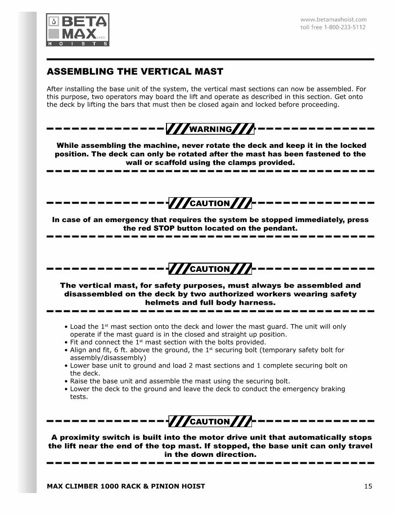
ASSEMBLING THE VERTICAL MAST
After installing the base unit of the system, the vertical mast sections can now be assembled. Forthis purpose, two operators may board the lift and operate as described in this section. Get ontothe deck by lifting the bars that must then be closed again and locked before proceeding.
While assembling the machine, never rotate the deck and keep it in the lockedposition. The deck can only be rotated after the mast has been fastened to the
wall or scaffold using the clamps provided.
In case of an emergency that requires the system be stopped immediately, pressthe red STOP button located on the pendant.
The vertical mast, for safety purposes, must always be assembled anddisassembled on the deck by two authorized workers wearing safety
helmets and full body harness.
• Load the 1st mast section onto the deck and lower the mast guard. The unit will onlyoperate if the mast guard is in the closed and straight up position.
• Fit and connect the 1st mast section with the bolts provided.• Align and fit, 6 ft. above the ground, the 1st securing bolt (temporary safety bolt for
assembly/disassembly)• Lower base unit to ground and load 2 mast sections and 1 complete securing bolt on
the deck.• Raise the base unit and assemble the mast using the securing bolt.• Lower the deck to the ground and leave the deck to conduct the emergency braking
tests.
A proximity switch is built into the motor drive unit that automatically stopsthe lift near the end of the top mast. If stopped, the base unit can only travel
in the down direction.
16 MAX CLIMBER 1000 RACK & PINION HOIST
If any of the acting limit switches and sensors detect an “open” condition, allpower will be cut to the system. To restore power, depress the green
button on the pendant.
If the nuts and bolts of the mast sections are not tightened,the system could overturn.
CONTINUATION OF ASSEMBLING THE VERTICAL MAST
• Raise the deck to the top limit of the pre-assembled mast, lower the mast guard (1) andset the next mast section in place making surethe bolts are tightened.
• To reactivate ascent, always put the mastguard (1) in the closed and straight upposition.
• Proceed as described above for the remainingmast sections until system is built to desiredheight.
• If necessary, attach floor stops (3) at desiredlevels during mast assembly. The floor stop willallow the unit to automatically stop at pre-setlevels.
• Make sure that each floor access is properlycordoned off and fitted with warningsigns…”free fall hazard.”
• Attach cable guides (4) every 30-ft. in normalconditions and every 20 ft. in windy conditions.
• Secure the vertical mast to the building orscaffold every 20-ft. using clamps provided (2).
• After assembling the last mast section, fit theup limit switch. Install the last wall or scaffoldclamp even if the distance from the previousone is less than 20 ft., also make sure the MastStraightening Tie is attached at this positionusing the 90 degree fixed clamp.
• After assembling the vertical mast, lower thedeck to the ground.
• Remove the pendant from the on-board controlpanel and reconnect it to the standardoperating pendant connector.
MAX CLIMBER 1000 RACK & PINION HOIST 17
Should the electric power supply fail while assembling or disassembling thesystem, and consequently the deck stops with persons on board, the lift can be
lowered by operating the motor brake following these steps:
• Take the release lever (1)screwed on the motorcasing and screw it ontothe nearby hole
• Release the brake bypulling the lever (2) veryslowly to perform a veryslow descent down to theheight where one can exitthe deck.
It is very important that the manual descent be done very slowly (no more than 20 fpm) because aquick descent will activate the emergency over-speed brake. Once the emergency over-speedbrake is activated the unit must move up to begin using the manual brake release again and with-out power the unit is unable to move up or down.
THE SYSTEM IS NOW READY FOR REGULAR SERVICE AND NO PERSON IS PERMITTED TORIDE ON THE DECK.
To disassemble the system, follow instructions on previous pages but in reverse order.
18 MAX CLIMBER 1000 RACK & PINION HOIST
EMERGENCY BRAKE TESTS
The emergency over-speed brake test must conducted every 3 months and/or whenever the sys-tem is assembled by trained personnel.
To conduct the test the following conditions must be met:
• The machine must be firmly secured• The access under the deck must be completely cleared and cordoned off• The loading deck must be raised to a height of 11.5 ft. above the ground• The machine must be unloaded
To simulate the operation of the emergency brake, the motor brake must be disabled. By disablingthe brake, the loading deck accelerates down until the emergency brake is applied. Therefore,trained workers must perform this operation with utmost care. Take the following steps:
• Take the release lever (1) that is screwed on themotor casing and screw it into the nearbythreaded hole.
• Connect the lever (1) with a rope made of nylonor similar material at least 1/4-1/2 inches indiameter
• Move about 10 ft. from the loading deck and pullthe rope. This action will open the motor brake.
• At this point the unit always descends faster untilthe emergency brake is activated.
• The downward movement should not exceed 12inches from when emergency brake is activateduntil locked.
• Should the unit not stop, immediately release therope to reactivate the motor brake (to stop themachine)
• In this case, immediately contact themanufacturer or dealer since the emergencybrake is not operating
• Should the test be positive, load the machinewith 550 lbs. and then 1100 lbs. and conduct testagain.
• After checking efficiency of emergency brake,lower the unit to ground by first pressing upbutton, this will reactivate the emergency brakeand then pressing the down button.
• The loading deck will stop at the bottom limitswitch
• Remove the rope, unscrew the lever (1) andplace it in the motor casing.
NEVER LEAVE THE RELEASE LEVER IN THE BRAKE!
Should the braking of either the motor brake or the emergency over-speed brake be too slow ortoo sudden, the brake control must be adjusted by following instructions in the section, “NON-ROUTINE MAINTENANCE”,page 24.
MAX CLIMBER 1000 RACK & PINION HOIST 19
WALL MOUNTING
Standard Wall Mounting:
The wall mounting, which must be secured every 20-ft., is used to vertically support the wholemast tower and is a very important element to the safe and proper use of the machine. Therefore,make sure all screws and clamps are tightened and check frequently.
Not to interfere with the bolts, fasten the release lever (a) of the turning plateparallel to the deck wall.
20 MAX CLIMBER 1000 RACK & PINION HOIST
SPECIAL WALL MOUNTING
• Place the element (1) by first loosening the bolt (3). Then place element (2) andadjust its distance.
• Fit element (1) and (2) to a wall with wall plugs or to a metal frame with swivelclamps able to bear the indicated loads.
• Check the vertical alignment of the unit. Loosen the bolt (3) until it touches the pipeof the vertical mast, this stiffens the securing point, do not secure the corner forcement of similar structures.
Use 5/8wall plugs suitable both for the indicated loads and the type of wall material. Should thelift be connected to scaffold, make sure the scaffold can bear the transmitted loads.
Not to interfere with the bolts, fasten the release lever (a) of the turning plateparallel to the deck wall.
MAX CLIMBER 1000 RACK & PINION HOIST 21
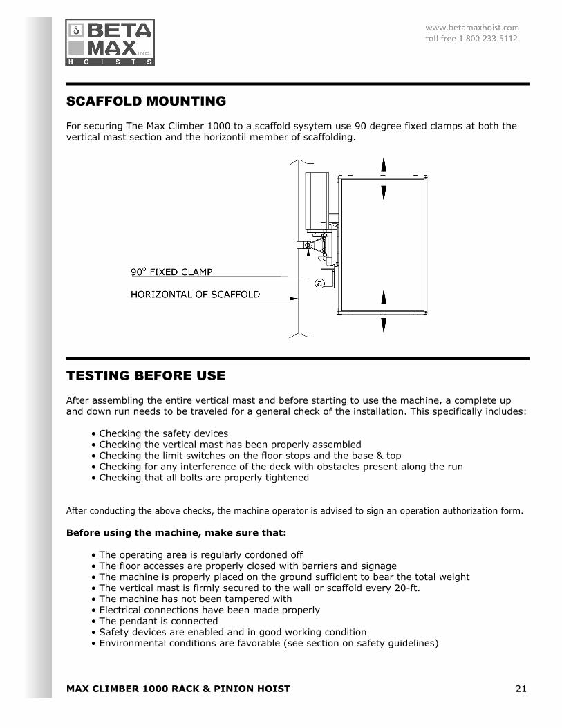
SCAFFOLD MOUNTING
For securing The Max Climber 1000 to a scaffold sysytem use 90 degree fixed clamps at both thevertical mast section and the horizontil member of scaffolding.
TESTING BEFORE USE
After assembling the entire vertical mast and before starting to use the machine, a complete upand down run needs to be traveled for a general check of the installation. This specifically includes:
• Checking the safety devices• Checking the vertical mast has been properly assembled• Checking the limit switches on the floor stops and the base & top• Checking for any interference of the deck with obstacles present along the run• Checking that all bolts are properly tightened
After conducting the above checks, the machine operator is advised to sign an operation authorization form.
Before using the machine, make sure that:
• The operating area is regularly cordoned off• The floor accesses are properly closed with barriers and signage• The machine is properly placed on the ground sufficient to bear the total weight• The vertical mast is firmly secured to the wall or scaffold every 20-ft.• The machine has not been tampered with• Electrical connections have been made properly• The pendant is connected• Safety devices are enabled and in good working condition• Environmental conditions are favorable (see section on safety guidelines)
22 MAX CLIMBER 1000 RACK & PINION HOIST
MACHINE CONTROLS AND OPERATOR’S GUIDE
Ensure that the red, emergency stop button is not depressed.
REGULAR OPERATION:
You must first press the green engage button to engage contacts in the controller. The hoist is nowready for regular operation. Depress the up or down button to raise or lower the basket. The emer-gency stop button will disconnect all power to the system and should only be used in emergencysituations where normal operation must stop immediately. When the emergency stop button hasbeen depressed you must start again by depressing the engage button to ready for up or downmovement.
FLOOR BY-PASS OPERATION:
The Max Climber can be operated with optional floor stops (6)(see section on assembling the vertical mast) which allowthe basket to stop at pre-set floors. When raising the basketthe system will automatically stop when the basket detects afloor stop. To by-pass any floor stop you must press both theblack, floor by-pass button and the up or down buttonsimultaneously. If the basket stops at a floor stop, you mustpress the floor by-pass button and the up or down button to
begin operation again.
The main control panel is fitted with a power knob (7) witha door lock and a phase inverter function. Turn the powerknob to activate the electric power supply.
MAX CLIMBER 1000 RACK & PINION HOIST 23
START UP:
To start up the machine:
• Enable the power knob on the control panel• Grip the pendant• Press the start button• Press the up button to raise the deck a few feet.• Release the up button and check the machine stops regularly (must stop instantly)• Press the down button and return to the ground.• Enable ascent until the required level has been reached• When the required level has been reached the operator on that level may open the
barrier, release the stop lock of the turning plate and turn the deck.• Lift the protecting bar and lower the access ramp of the deck.• Unload goods• Close the ramp, lower the protecting bar and turn the deck to the regular operating
position.• Close the barrier on the working level again.
WHEN NOT USING THE MACHINE, MAKE SURE THE DECK IS LOWERED TO THEGROUND, DISABLE THE MAIN POWER KNOB ON THE CONTROL PANEL TURNING IT
TO “0”, UNPLUG FROM POWER SUPPLY AND REMOVE PENDANT FROM POWERSUPPLY CABLE TO PREVENT USE BY UNAUTHORIZED PERSONS.
24 MAX CLIMBER 1000 RACK & PINION HOIST
ADJUSTMENTS AND REGULATIONS
The Max Climber 1000 does not require any special adjustment after being delivered. However, ifneed be, take the following steps to adjust the service and emergency over-speed brakes:
A. Should the machinery not be moving and tend to slip, the service brake needs adjusting. Thisoperation must be carried out only by the technical support center or by a trained and authorizedtechnician.
• Lower the deck to the ground• Disable the electric power line by using the main power knob (1) on the control panel•Open the motor cover•Screw the motor brake ring nut (4) with a wrench clockwise about 180 degrees so as
to increase pressure of the springs (5) on the brake disc (6). Conduct an unloadedoperation test and a fully loaded operation test.
•Refit the motor cover and enable the main power knob of the control panel.
B. Instructions for adjusting the emergency over-speed brake can be found in the section “NON-ROUTINE MAINTENANCE” on page 25.
MAX CLIMBER 1000 RACK & PINION HOIST 25
MAINTENANCE OF THE MAX CLIMBER 1000
The Max Climber 1000 has been designed and manufactured with the correct components to re-duce maintenance and to ensure efficient operation. The user has to make sure periodic mainte-nance is carried out to always maximize machine efficiency. The simple operations and the checksrequired, if performed regularly, let you always keep the machine in efficient and safe workingorder.
The main steps that the user has to take are described below:
PERIODIC MAINTENANCE
At least once a week and after any adverse weather conditions, check the whole machine. This is tospecifically include:
• Efficiency of electric safety devices• Wall-mounted or scaffold-mounted securing bolts are stable and tightened
At least once per month check that the:
• Bolts are tightened on each vertical mast section and on each mounting clamp• Gear motor unit clamping bolts are tightened• Mast sections have not moved, shifted or rotated• Motor drive guide and sliding rollers smoothly run on the column• Gear motor unit works efficiently. Also check its noise level to see if there are any
gear irregularities• Gear reducer is correctly lubricated and the motor brake works efficiently• Emergency over-speed brake works efficiently, by greasing the pins and the ratchet
gear.• Power supply/pendant control cable are in good working order• Whole machine is clean• Rack is greased to reduce wear on both the rack and the lifting pinion
NON-ROUTINE MAINTENANCE
At least once per month or whenever you doubt their efficiency, check the service and emergencyover-speed brakes. These checks need to be performed by a trained and authorized person.
All maintenance jobs must be carried out with the deck on the ground and withthe power supply off. Unplug the power supply cable and switch off the main
power knob on the control panel.
26 MAX CLIMBER 1000 RACK & PINION HOIST
Gear Motor:
• Change the oil for the first time after 100 hoursof operation
• Then change the oil every 2000 hours ofoperation or at least once per year
• Empty and fill through the caps provided• The gear reducer is immediately emptied after
operation with hot oil to prevent deposits• Clean the caps (especially the magnetic cap)
before putting them back on
Adjusting the service brake:
See section on adjustments and regulations on page 24
Adjusting the Emergency Over-speed Brake:
• Lower the machine to the ground• Disable the electric power line with the main
power knob on the control panel• Open the emergency over-speed brake guard
by removing the screws• Adjust all brake disc pressure screws (4) until
the required load has been reached• Use the lubricator (5) to grease the pin of the
ratchet gear (6)• Conduct an operational test before using the
machine as described on page “Emergency BrakeTests”
In case of damage, other non-routine maintenance or repair jobs must be carried out only by thetechnical support department that will issue a regular maintenance declaration and enter it in thismanual in the assigned space.
MAX CLIMBER 1000 RACK & PINION HOIST 27
TROUBLE-SHOOTING
The potential failures that may occur on the Max Climber System can mainly be attributed to the electricsystem. In this case it is always advisable to contact the manufacturer’s technical support department
28 MAX CLIMBER 1000 RACK & PINION HOIST
To ensure safety, reliability and the validity of the guarantee, always use onlyoriginal spare parts!