10•18W #891/3• 8/06 W164 N9221 Water Street • P.O. Box 450 • Menomonee Falls, Wisconsin 53052-0450 USA PHONE: 262.251.3800 • 800.558.8744 USA/CANADA FAX: 262.251.7067 • 800.329.8744 U.S.A. ONLY WEBSITE: www.alto-shaam.com PRINTED IN U . S . A . ® Holding Cabinets Electric Models: 10•18W 12•20W 12•20MW 20•20W 20•20MW • INSTALLATION • OPERATION • MAINTENANCE 12•20MW 20•20MW
Transcript
10•18W
#891/3• 8/06
W 1 6 4 N 9 2 2 1 Wa t e r S t r e e t • P.O. Box 450 • Menomonee Fa l ls , Wiscons in 53052-0450 USAPHONE: 262.251.3800 • 800.558.8744 USA/CANADA FAX: 262.251.7067 • 800.329.8744 U.S.A. ONLY
This Alto-Shaam appliance has beenthoroughly tested and inspected to insure onlythe highest quality unit is provided. Uponreceipt, check for any possible shippingdamage and report it at once to the deliveringcarrier. See Transportation Damage and
Claims section located in this manual.
This appliance, complete with unattacheditems and accessories, may have beendelivered in one or more packages. Check toensure that all standard items and optionshave been received with each model asordered.
Save all the information and instructionspacked with the appliance. Complete andreturn the warranty card to the factory as soonas possible to assure prompt service in theevent of a warranty parts and labor claim.
This manual must be read and understoodby all people using or installing the equipmentmodel. Contact the Alto-Shaam servicedepartment if you have any questionsconcerning installation, operation, ormaintenance.
NOTE: All claims for warranty must includethe full model number and serialnumber of the unit.
UNPACKING
1. Carefully remove theappliance from the carton or crate.
NOTE: Do not discard thecarton and otherpackaging materialuntil you haveinspected the unitfor hidden damageand tested it forproper operation.
2. Read all instructions in this manual carefullybefore initiating the installation of thisappliance.
DO NOT DISCARD THIS MANUAL.
This manual is considered to be part of theappliance and is to be provided to theowner or manager of the business or to theperson responsible for training operators.Additional manuals are available from the
Alto-Shaam service department.
3. Remove all protective plastic film,packaging materials, and accessories fromthe appliance before connecting electricalpower. Store any accessories in aconvenient place for future use.
Knowledge of proper procedures is essential to thesafe operation of electrically and/or gas energizedequipment. In accordance with generally acceptedproduct safety labeling guidelines for potentialhazards, the following signal words and symbolsmay be used throughout this manual.
Used to indicate thepresence of a hazard thatwill cause severe personalinjury, death, or substantialproperty damage if thewarning included with thissymbol is ignored.
Used to indicate thepresence of a hazard thatcan cause personal injury,possible death, or majorproperty damage if thewarning included with thissymbol is ignored.
Used to indicate thepresence of a hazard thatcan or will cause minor ormoderate personal injury orproperty damage if thewarning included with thissymbol is ignored.
Used to indicate thepresence of a hazard thatcan or will cause minorpersonal injury, propertydamage, or a potentialunsafe practice if thewarning included with thissymbol is ignored.
Used to notify personnel ofinstallation, operation, ormaintenance information that isimportant but not hazard related.
1. This appliance is intended to cook, hold orprocess foods for the purpose of humanconsumption. No other use for this applianceis authorized or recommended.
2. This appliance is intended for use incommercial establishments where alloperators are familiar with the purpose,limitations, and associated hazards of thisappliance. Operating instructions andwarnings must be read and understood by all operators and users.
3. Any troubleshooting guides, component views,and parts lists included in this manual are forgeneral reference only and are intended for useby qualified technical personnel.
4. This manual should be considered apermanent part of this appliance. Thismanual and all supplied instructions,diagrams, schematics, parts lists, notices, andlabels must remain with the appliance if theitem is sold or moved to another location.
1. This appliance, complete with unattached itemsand accessories, may be delivered in one or morepackages. Check to insure that all items orderedhave been received.
2. This appliance is designed for the purpose ofmaintaining hot food at a temperature for safeconsumption. The unit must be installed on alevel surface in a location that will permit theequipment to function for its intended purposeand allow adequate access for proper cleaningand maintenance.
3. The appliance must not be installed in any areawhere it will be affected by steam, grease, dripping water, high temperatures, or any otherseverely adverse conditions.
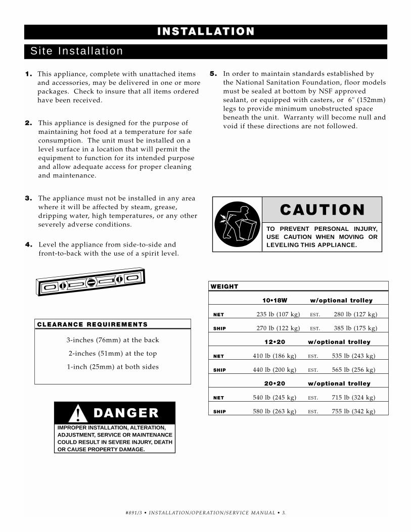
4. Level the appliance from side-to-side and front-to-back with the use of a spirit level.
5. In order to maintain standards established by the National Sanitation Foundation, floor modelsmust be sealed at bottom by NSF approvedsealant, or equipped with casters, or 6" (152mm)legs to provide minimum unobstructed spacebeneath the unit. Warranty will become null andvoid if these directions are not followed.
INSTALLATION
Si te Insta l la t ion
TO PREVENT PERSONAL INJURY, USE CAUTION WHEN MOVING OR LEVELING THIS APPLIANCE.
IMPROPER INSTALLATION, ALTERATION, ADJUSTMENT, SERVICE OR MAINTENANCECOULD RESULT IN SEVERE INJURY, DEATHOR CAUSE PROPERTY DAMAGE.
1. An identification tag is permanently mountedon the cabinet.
2. Plug the unit into a properly grounded receptacle ONLY. Arcing will occur when connecting or disconnecting the unit unless all controls are in the “OFF” position.
3. Position the unit so the cord is easily accessiblein case of any emergencies. If necessary, aproper receptacle or outlet configuration, asrequired for the unit, must be installed by alicensed electrician in accordance with applicable, local electrical codes.
230V:To prevent an electrical shock hazard between theappliance and other appliances or metal parts inclose vicinity, an equalization-bonding stud is provided. An equalization bonding lead must be connected to this stud and the other appliances /metal parts to provide sufficient protectionagainst potential difference. The terminal ismarked with the following symbol.
NOTE: The appliance must be connected to an electrical circuit that is protected by an external GFCI outlet.
Elect r ica l Insta l la t ion
ELECTRICAL CONNECTIONS MUST BE MADE BY A QUALIFIED SERVICE TECHNICIAN IN ACCORDANCE WITH APPLICABLE ELECTRICAL CODES.
To avoid electrical shock, this appliance MUST be adequately grounded in accordance with local electrical codes or, in the absence of local codes, with the current edition of the National Electrical Code ANSI/NFPA No. 70. In Canada, all electrical connections are to be made in accordance with CSA C22.1, Canadian Electrical Code Part 1 or local codes.
NEMA 6-20P20A-250V PLUG
CEE 7/7220-230V PLUG
NEMA 6-20P20A-250V PLUG
CEE 7/7220-230V PLUG
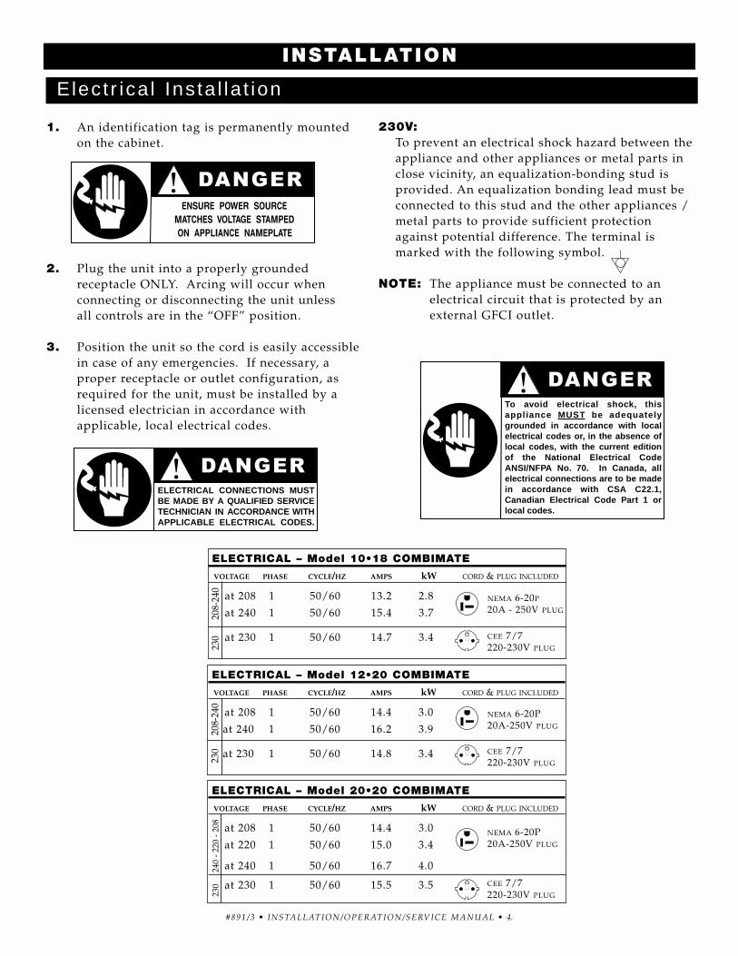
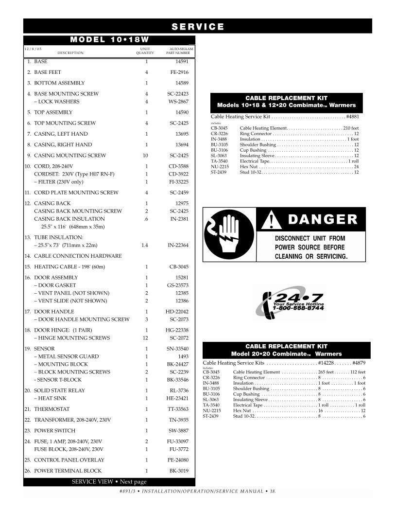
ELECTRICAL – Model 10•18 COMBIMATE
VOLTAGE PHASE CYCLE/HZ AMPS kW CORD & PLUG INCLUDED
at 208 1 50/60 13.2 2.8
at 240 1 50/60 15.4 3.7
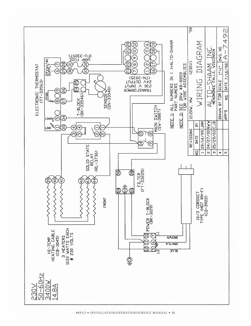
at 230 1 50/60 14.7 3.4
NEMA 6-20P
20A - 250V PLUG
CEE 7/7220-230V PLUG23
020
8-24
0
ELECTRICAL – Model 12•20 COMBIMATE
VOLTAGE PHASE CYCLE/HZ AMPS kW CORD & PLUG INCLUDED
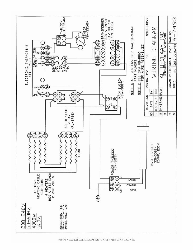
at 208 1 50/60 14.4 3.0
at 240 1 50/60 16.2 3.9
at 230 1 50/60 14.8 3.4
230
208-
240
ELECTRICAL – Model 20•20 COMBIMATE
VOLTAGE PHASE CYCLE/HZ AMPS kW CORD & PLUG INCLUDED
User Safety In format ionThis appliance is intended for use in commercial
establishments where all operators are familiar with thepurpose, limitations, and associated hazards of thisappliance. Operating instructions and warnings mustbe read and understood by all operators and users.
1. Make sure the unit is connected to the
appropriate power source.
2. Use hand protection when handling
hot items.
3. Preheat the unit for 30 minutes before use.
4. Be certain only hot foods are placed
into the cabinet.
5. Do not operate the holding cabinet
without the Roll-in Cart on Models 12•20
and 20•20 or Slide-in Pan Rack on Model
10•18W.
HEATING CHARACTERISTICSThe cabinet is equipped with a special,
low-heat-density heating cable. Through the Halo Heat concept, the heating cable is mounted against the walls of the warming compartment toprovide an evenly applied heat source controlledby a thermostat. The design and operational characteristics of the cabinet eliminate the need for a moisture pan or a heat circulating fan.Through even heat application, the quality of afood product is maintained up to as much asseveral hours.
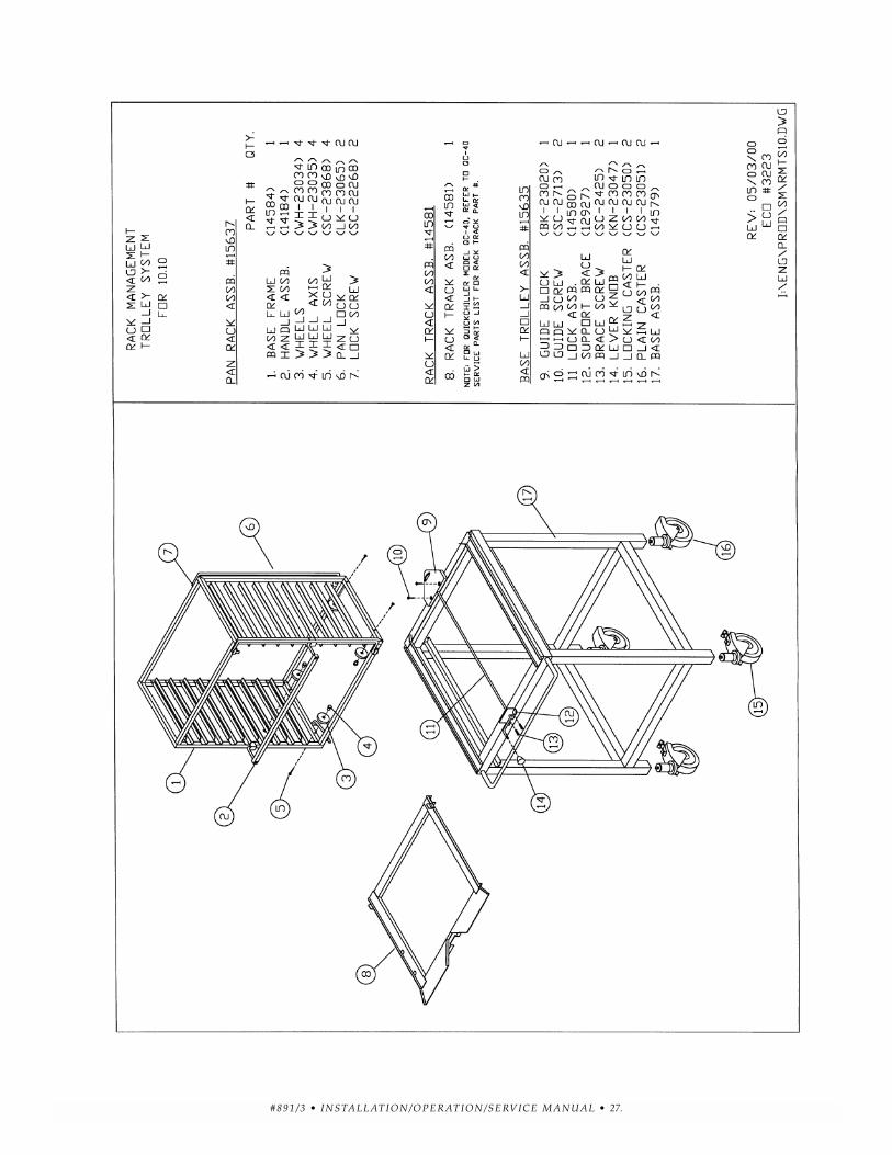
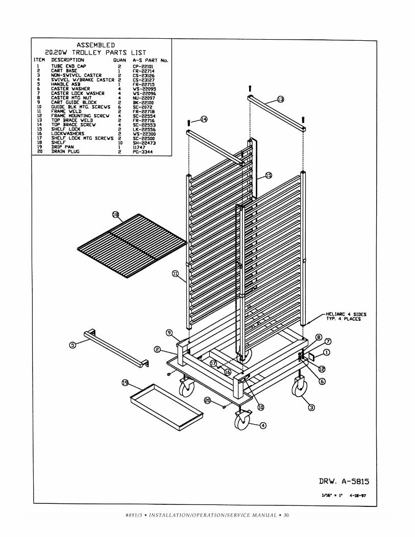
The primary purpose of the Model 10•18W,12•20, and 20•20 Holding Cabinet is to operate as a functional extension of the CombithermCombination Oven/ Steamer. The combinationoven is for high volume production – the HaloHeat companion holding cabinet preserves the quality and extends the longest possible holdinglife. The Slide-In-Pan-Rack for the 10•18W and the Roll-In Cart for the 12•20 and 20•20 arecompletely interchangeable between theCombitherm Oven and the Halo Heat CompanionHolding Cabinet, along with compatible Alto-Shaam Quickchillers.
The Combitherm Combination Oven/Steamer,along with the Halo Heat companion holding cabinetand Alto-Shaam Quickchiller give the food serviceoperator the advantage of advance full-loadpreparation, better work-load scheduling, and theability to hold the product for prolonged periodswithout major deterioration.
BEFORE INITIAL USE:Before operating the unit, clean both the interior andexterior with a clean, damp cloth and mild soapsolution. Rinse carefully with a sponge and cleanwater. Clean and install the Roll-in Cart on Models12•20 and 20•20 or Slide-in Rack on the Model 10•18W.
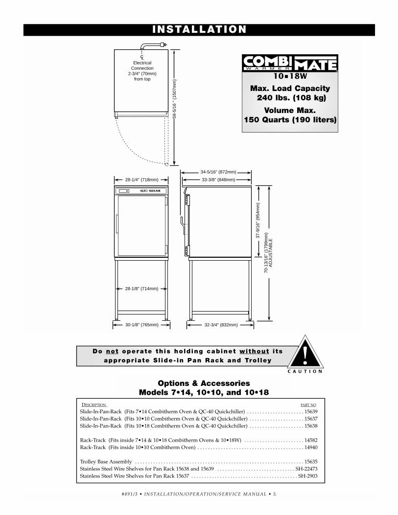
PRODUCT\PAN CAPACITY - Model 10•18 COMBIMATE
240 lbs (108 kg) MAXIMUM
VOLUME MAXIMUM: 150 QUARTS (190 LITERS)
FULL-SIZE PANS: Twenty (20) 20" x 12" x 2-1/2" MAXIMUM
GN 1/1: Twenty (20) (530mm x 325mm x 65mm)
GN 2/1: Ten (10) (650mm x 530mm x 65mm)
FULL-SIZE SHEET PANS: Five (5) 18" x 26" x 1"
(10 with added Shelves)
PRODUCT\PAN CAPACITY - Model 12•20 COMBIMATE
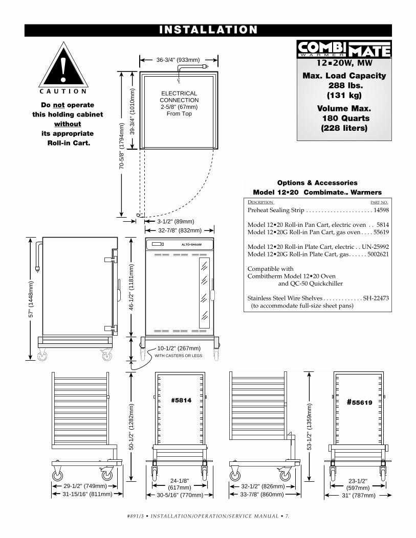
288 lbs (131 kg) MAXIMUM
VOLUME MAXIMUM: 180 QUARTS (228 LITERS)
FULL-SIZE PANS: Twenty-four (24) 20" x 12" x 2-1/2" MAXIMUM
GN 1/1: Twenty-four (24) (530mm x 325mm x 65mm)
GN 2/1: Twelve (12) (650mm x 530mm x 65mm)
FULL-SIZE SHEET PANS: Six (6) 18" x 26" x 1"
(12 with added Shelves)
PRODUCT\PAN CAPACITY - Model 20•20 COMBIMATE
480 lbs (218 kg) MAXIMUM
VOLUME MAXIMUM: 300 QUARTS (380 LITERS)
FULL-SIZE PANS: Forty (40) 20" x 12" x 2-1/2" MAXIMUM
The L.E.D., Light Emitting Diode, referred to is an electronicdevice providing illumination. The control has a three-digitL.E.D. display. When the warming cabinet is in operation,the L.E.D. will show the chamber's internal temperature.The display will also show programming and diagnosticinformation.
ON/OFF Rocker Switch
The Power On/Off Rocker Switchpositions may be marked with theinternational "I" for On and "O" for Off.
UP/DOWN Arrow Rocker Button
The UP/DOWN arrow rocker button is used toincrease or decrease the set-point temperature.The minimum set-point temperature is 90°F (32°C) while the maximum set-pointtemperature is 200°F (93°C).
SET Button
The SET button is used to display the currentset-point temperature or program a new set-point temperature. Pushing the SET buttononce will display the set-point temperaturevalue for five seconds. Holding the SET buttonallows the programming mode to becomeactive.
L.E.D. Display
The L.E.D. display will show the set-pointtemperature value when programming, orthe warming chamber's temperature whencalling for heat. When programming anew set-point temperature, the L.E.D.1indicator will blink. When a new set-pointtemperature is chosen, the ChamberTemperature L.E.D. will flash three times to confirm.
SET
°F
CHAMBERTEMPERATURE
L.E.D.
L.E.D.1
200
HEAT INDICATOR L.E.D.
The Heat Indicator L.E.D. will illuminateand remain lit while the unit is calling forheat. It will go out when the airtemperature inside the warming chamberreaches the set-point temperature on thecontrol.
ERROR CODE DISPLAYS
Open-Circuited
If "OOO " or "PFO " is displayed in theError Code L.E.D., the sensor is open-circuited. Follow Trouble Shooting Guideinstructions in this Operation and CareManual.
Short-Circuited
If "CCC " or "PFC " is displayed in theError Code L.E.D., the sensor is short-circuited. Follow Trouble Shooting Guideinstructions in this Operation and CareManual.
ERROR CODE INDICATOR L.E.D.
If either of the above mentioned errorscodes should occur, the Error CodeIndicator L.E.D. will be illuminated andremain so until error is cleared.
Press the "ON" or "I" position of the rocker switch to turn on control.
CHANGE SET-POINT TEMPERATURE
Press and hold the SET button for at least 3 seconds. After L.E.D.1 indicatorblinks, release the Set Button. The control isnow in the programming mode.
Press and hold the UP or DOWN arrowrocker button to change the value shown inthe display. Store the value by pressing theSET button.
The new set-point value will flash threetimes to confirm.
HEAT INDICATOR L.E.D.
The Heat Indicator L.E.D. will illuminate asthe warming chamber calls for heat. It willextinguish when the warming chamber'sinterior temperature reaches the set-point.
PREHEATING THE UNIT
Always preheat the unit at 200°F (93°C) for 30 minutes beforeloading the cabinet with hot food.
NOTE: Do not operate the holding cabinet withoutthe Roll-in Cart on Models 12•20 and 20•20 or Slide-in Pan Rack on Model 10•18W.
LOADING THE CABINET
Load the cabinet with hot food only. The purpose of this unit is to maintain hot food at proper servingtemperature. Use a food thermometer to make certain allfood has reached an internal temperature range of 140° to 160°F (60° to 71°C).
Make certain door is securely closed after loading. Reset the control to 160°F (71°C).
This will not necessarily be the final setting. Proper temperature range for the food being held will depend on the type and quantity of product. It is advisable to periodically check the internal temperature of each item to assure maintenance of proper food servingtemperature.
°F
CHAMBERTEMPERATURE
L.E.D.
L.E.D.1
200
SET
+
C A U T I O N
The unit should be unplugged and a qualified service technician should be consulted if anyof the following situations occur:
• The Heat Indicator L.E.D. does notilluminate after normal start-up.
• The warming cabinet does not hold the temperature as set.
• The warming cabinet fails to heat with theL.E.D. illuminated.
• The cabinet heats continuously with the control “OFF”.
Chefs, cooks and other specialized food servicepersonnel employ varied methods of cooking.Proper holding temperatures for a specific foodproduct must be based on the moisture content of the product, product density, volume, and proper serving temperatures. Safe holding temperatures must also be correlated with palatability in determining the length of holdingtime for a specific product.
Halo Heat maintains the maximum amount ofproduct moisture content without the additionof water, water vapor, or steam. Maintainingmaximum natural product moisture preserves thenatural flavor of the product and provides a moregenuine taste. In addition to product moistureretention, the gentle properties of Halo Heat maintain a consistent temperature throughout thecabinet without the necessity of a heatdistribution fan, thereby preventing furthermoisture loss due to evaporation or dehydration.
When product is removed from a high temper-ature cooking environment for immediate transferinto equipment with the lower temperaturerequired for hot food holding, condensation canform on the outside of the product and on theinside of plastic containers used in self-serviceapplications. Allowing the product to release theinitial steam and heat produced by hightemperature cooking can alleviate this condition.To preserve the safety and quality of freshlycooked foods however, a maximum of 1 to 2minutes must be the only time period allowed forthe initial heat to be released from the product.
This unit is equipped with a thermostat controlbetween 60° and 200°F (16° and 93°C). If the unitis equipped with vents, close the vents for moistholding and open the vents for crisp holding. Use a metal-stemmed thermometer to measure the internal temperature of the product beingheld. Adjust the thermostat setting to achieve the best overall setting based on internal producttemperature.
H O L D I N G T E M P E R A T U R E R A N G EMEAT FAHRENHEIT CELSIUS
BEEF ROAST — Rare 140°F 60°C
BEEF ROAST — Med/Well Done 160°F 71°C
BEEF BRISKET 160° — 175°F 71° — 79°C
CORN BEEF 160° — 175°F 71° — 79°C
PASTRAMI 160° — 175°F 71° — 79°C
PRIME RIB — Rare 140°F 60°C
STEAKS — Broiled/Fried 140° — 160°F 60° — 71°C
RIBS — Beef or Pork 160°F 71°C
VEAL 160° — 175°F 71° — 79°C
HAM 160° — 175°F 71° — 79°C
PORK 160° — 175°F 71° — 79°C
LAMB 160° — 175°F 71° — 79°C
POULTRY
CHICKEN — Fried/Baked 160° — 175°F 71° — 79°C
DUCK 160° — 175°F 71° — 79°C
TURKEY 160° — 175°F 71° — 79°C
GENERAL 160° — 175°F 71° — 79°C
FISH/SEAFOOD
FISH — Baked/Fried 160° — 175°F 71° — 79°C
LOBSTER 160° — 175°F 71° — 79°C
SHRIMP — Fried 160° — 175°F 71° — 79°C
BAKED GOODS
BREADS/ROLLS 120° — 140°F 49° — 60°C
MISCELLANEOUS
CASSEROLES 160° — 175°F 71° — 79°C
DOUGH — Proofing 80° — 100°F 27° — 38°C
EGGS —Fried 150° — 160°F 66° — 71°C
FROZEN ENTREES 160° — 175°F 71° — 79°C
HORS D'OEUVRES 160° — 180°F 71° — 82°C
PASTA 160° — 180°F 71° — 82°C
PIZZA 160° — 180°F 71° — 82°C
POTATOES 180°F 82°C
PLATED MEALS 180°F 82°C
SAUCES 140° — 200°F 60° — 93°C
SOUP 140° — 200°F 60° — 93°C
VEGETABLES 160° — 175°F 71° — 79°C
The holding temperatures listed are suggested guidelines only.
It is important to guard againstcorrosion in the care of
stainless steel surfaces.Harsh, corrosive, orinappropriate chemicals cancompletely destroy the
protective surface layer of stainless steel. Abrasivepads, steel wool, or metal implements will abradesurfaces causing damage to this protective coatingand will eventually result in areas of corrosion.Even water, particularly hard water that containshigh to moderate concentrations of chloride, willcause oxidation and pitting that result in rust andcorrosion. In addition, many acidic foods spilledand left to remain on metal surfaces arecontributing factors that will corrode surfaces.
Proper cleaning agents, materials, andmethods are vital to maintaining the appearanceand life of this appliance. Spilled foods should beremoved and the area wiped as soon as possiblebut at the very least, a minimum of once a day.Always thoroughly rinse surfaces after using acleaning agent and wipe standing water as quicklyas possible after rinsing.
CLEANING AGENTS
Use non-abrasive cleaning products designed for useon stainless steel surfaces. Cleaning agents must bechloride-free compounds and must not containquaternary salts. Never use hydrochloric acid(muriatic acid) on stainless steel surfaces. Always usethe proper cleaning agent at the manufacturer'srecommended strength. Contact your local cleaningsupplier for product recommendations.
CLEANING MATERIALS
The cleaning function can usually be accomplishedwith the proper cleaning agent and a soft, cleancloth. When more aggressive methods must beemployed, use a non-abrasive scouring pad ondifficult areas and make certain to scrub with thevisible grain of surface metal to avoid surfacescratches. Never use wire brushes, metal scouringpads, or scrapers to remove food residue.
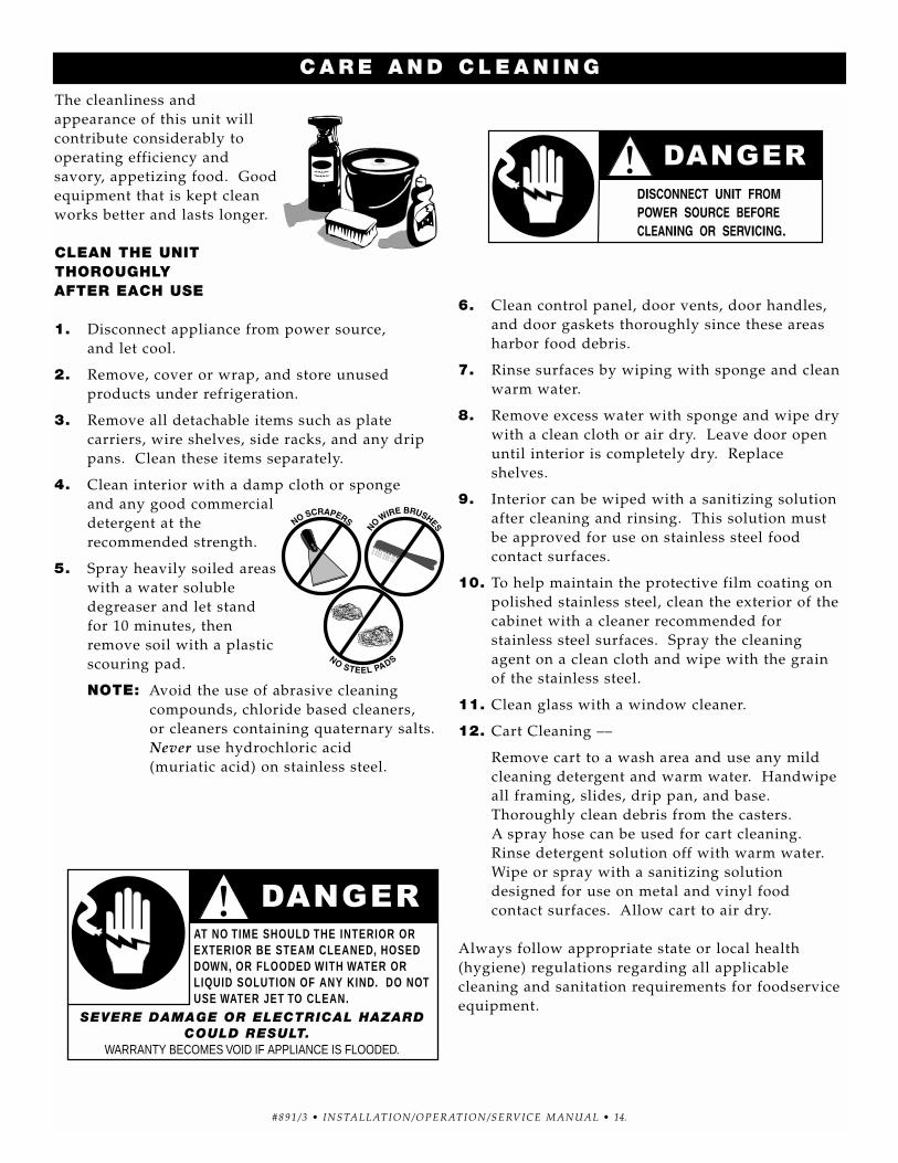
The cleanliness andappearance of this unit willcontribute considerably to operating efficiency andsavory, appetizing food. Goodequipment that is kept cleanworks better and lasts longer.
CLEAN THE UNIT THOROUGHLY AFTER EACH USE
1. Disconnect appliance from power source, and let cool.
2. Remove, cover or wrap, and store unused products under refrigeration.
3. Remove all detachable items such as platecarriers, wire shelves, side racks, and any drippans. Clean these items separately.
4. Clean interior with a damp cloth or sponge and any good commercialdetergent at therecommended strength.
5. Spray heavily soiled areaswith a water solubledegreaser and let standfor 10 minutes, thenremove soil with a plasticscouring pad.
NOTE: Avoid the use of abrasive cleaning compounds, chloride based cleaners, or cleaners containing quaternary salts.Never use hydrochloric acid (muriatic acid) on stainless steel.
6. Clean control panel, door vents, door handles,and door gaskets thoroughly since these areasharbor food debris.
7. Rinse surfaces by wiping with sponge and cleanwarm water.
8. Remove excess water with sponge and wipe drywith a clean cloth or air dry. Leave door openuntil interior is completely dry. Replaceshelves.
9. Interior can be wiped with a sanitizing solutionafter cleaning and rinsing. This solution must be approved for use on stainless steel food contact surfaces.
10. To help maintain the protective film coating onpolished stainless steel, clean the exterior of thecabinet with a cleaner recommended forstainless steel surfaces. Spray the cleaningagent on a clean cloth and wipe with the grainof the stainless steel.
11. Clean glass with a window cleaner.
12. Cart Cleaning ––
Remove cart to a wash area and use any mildcleaning detergent and warm water. Handwipeall framing, slides, drip pan, and base.Thoroughly clean debris from the casters. A spray hose can be used for cart cleaning.Rinse detergent solution off with warm water.Wipe or spray with a sanitizing solutiondesigned for use on metal and vinyl food contact surfaces. Allow cart to air dry.
Always follow appropriate state or local health(hygiene) regulations regarding all applicable cleaning and sanitation requirements for foodserviceequipment.
C A R E A N D C L E A N I N G
AT NO TIME SHOULD THE INTERIOR OR EXTERIOR BE STEAM CLEANED, HOSED DOWN, OR FLOODED WITH WATER OR LIQUID SOLUTION OF ANY KIND. DO NOT USE WATER JET TO CLEAN.
Food flavor and aroma are usually so closely related that it is difficult, if not impossible, to separate them.There is also an important, inseparable relationshipbetween cleanliness and food flavor. Cleanliness, topoperating efficiency, and appearance of equipmentcontribute considerably to savory, appetizing foods.Good equipment that is kept clean, works better andlasts longer.
Most food imparts its own particular aroma and many foods also absorb existing odors. Unfortunately,during this absorption, there is no distinction betweenGOOD and BAD odors. The majority of objectionableflavors and odors troubling food service operations arecaused by bacteria growth. Sourness, rancidity,mustiness, stale or other OFF flavors are usually theresult of germ activity.
The easiest way to insure full, natural food flavor isthrough comprehensive cleanliness. This means goodcontrol of both visible soil (dirt) and invisible soil(germs). A thorough approach to sanitation willprovide essential cleanliness. It will assure an attractiveappearance of equipment, along with maximumefficiency and utility. More importantly, a goodsanitation program provides one of the key elements in the prevention of food-borne illnesses.
A controlled holding environment for prepared foods is just one of the important factors involved in theprevention of food-borne illnesses. Temperaturemonitoring and control during receiving, storage,preparation, and the service of foods are of equalimportance.
The most accurate method of measuring safetemperatures of both hot and cold foods is by internalproduct temperature. A quality thermometer is aneffective tool for this purpose, and should be routinelyused on all products that require holding at a specifictemperature.
A comprehensive sanitation program should focus onthe training of staff in basic sanitation procedures. This includes personal hygiene, proper handling of rawfoods, cooking to a safe internal product temperature,and the routine monitoring of internal temperaturesfrom receiving through service.
Most food-borne illnesses can be prevented throughproper temperature control and a comprehensiveprogram of sanitation. Both these factors are importantto build quality service as the foundation of customersatisfaction. Safe food handling practices to preventfood-borne illness is of critical importance to the healthand safety of your customers. HACCP, an acronym forHazard Analysis (at) Critical Control Points, is a qualitycontrol program of operating procedures to assure foodintegrity, quality, and safety. Taking steps necessary toaugment food safety practices are both cost effectiveand relatively simple. While HACCP guidelines go farbeyond the scope of this manual, additional informationis available by contacting:
Center for Food Safety and Applied Nutrition Food and Drug Administration
1-888-SAFEFOOD
S A N I TAT I O N
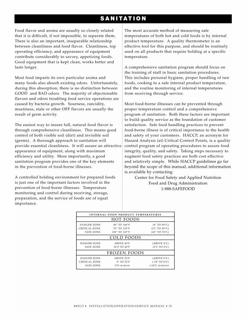
I N T E R N A L F O O D P R O D U C T T E M P E R AT U R E S
HOT FOODSDANGER ZONE 40° TO 140°F (4° TO 60°C)
CRITICAL ZONE 70° TO 120°F (21° TO 49°C)SAFE ZONE 140° TO 165°F (60° TO 74°C)
COLD FOODSDANGER ZONE ABOVE 40°F (ABOVE 4°C)
SAFE ZONE 36°F TO 40°F (2°C TO 4°C)
FROZEN FOODSDANGER ZONE ABOVE 32°F (ABOVE 0°C)
CRITICAL ZONE 0° TO 32°F (-18° TO 0°C)SAFE ZONE 0°F OR BELOW (-18°C OR BELOW)
ELECTRONIC CONTROL ACCURACY
The electronic control is a precise instrument and isdesigned to offer trouble-free service. If you suspectthe temperature inside the warming cabinet does notmatch the temperature indicated on the digitaldisplay, after stabilizing, follow the instructions listed below.
1. Check to make certain the unit voltage matchesthe power source. A power source less than thatrequired to operate the unit will result ininaccurate temperatures.
2. Verify the temperature inside the holdingcompartment with a qualify thermal indicator.
A. With the exception of the wire shelves,completely empty the holding compartment.
B. Make certain the holding cabinet sensor,located inside the holding compartment atthe left side of the unit, is completely clean.
C. Suspend the thermal indicator in the centerof the holding compartment.
D. Allow the temperature set on the electronicthermostat to stabilize for a minimum of onehour before comparing the digital displaywith the reading on the thermal indicator.
DO NOT OPEN THE CABINET DOOR(S)DURING THE TEMPERATURESTABILIZATION PERIOD.
If the reading on the thermal indicator does notmatch the digital display, there may be a problemwith the air sensor. See troubleshooting guide in thismanual, or call the factory service department foradvice.
5. Cannot control temperature butsensor and electronic control checkout OK.
6. Temperature readout incorrect.
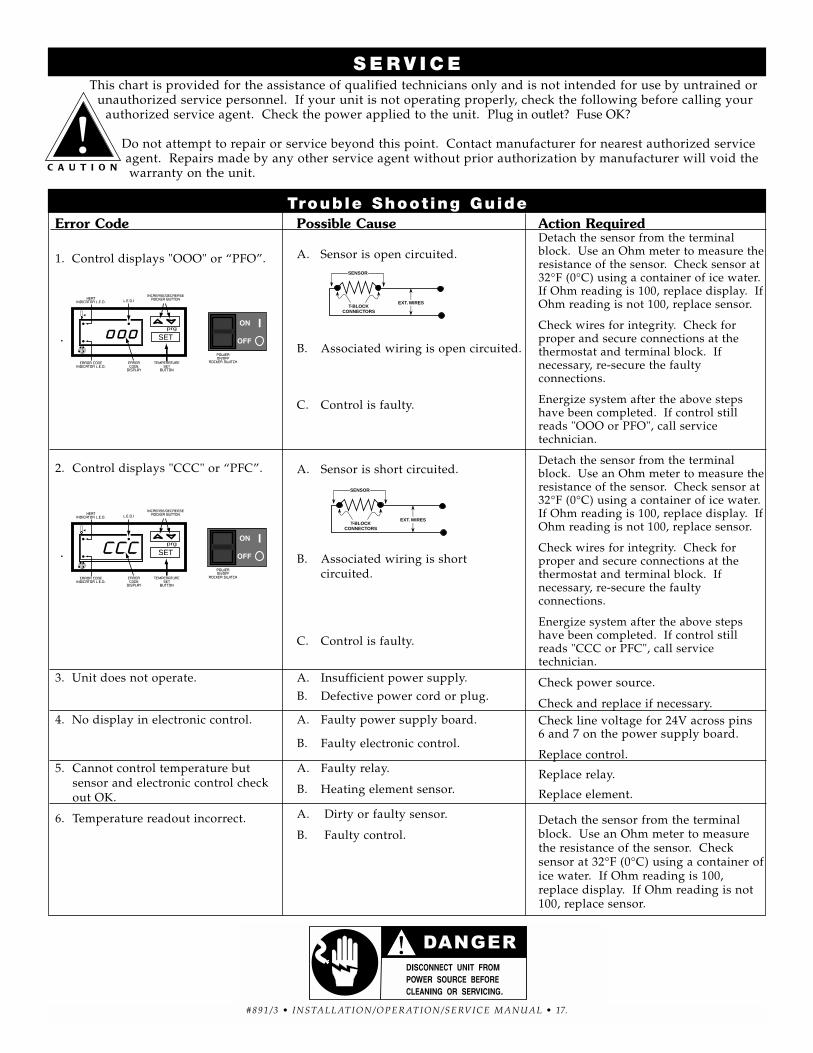
Possible Cause
A. Sensor is open circuited.
B. Associated wiring is open circuited.
C. Control is faulty.
A. Sensor is short circuited.
B. Associated wiring is shortcircuited.
C. Control is faulty.
A. Insufficient power supply.
B. Defective power cord or plug.
A. Faulty power supply board.
B. Faulty electronic control.
A. Faulty relay.
B. Heating element sensor.
A. Dirty or faulty sensor.
B. Faulty control.
Action RequiredDetach the sensor from the terminalblock. Use an Ohm meter to measure theresistance of the sensor. Check sensor at32°F (0°C) using a container of ice water.If Ohm reading is 100, replace display. IfOhm reading is not 100, replace sensor.
Check wires for integrity. Check forproper and secure connections at thethermostat and terminal block. Ifnecessary, re-secure the faultyconnections.
Energize system after the above stepshave been completed. If control stillreads "OOO or PFO", call servicetechnician.
Detach the sensor from the terminalblock. Use an Ohm meter to measure theresistance of the sensor. Check sensor at32°F (0°C) using a container of ice water.If Ohm reading is 100, replace display. IfOhm reading is not 100, replace sensor.
Check wires for integrity. Check forproper and secure connections at thethermostat and terminal block. Ifnecessary, re-secure the faultyconnections.
Energize system after the above stepshave been completed. If control stillreads "CCC or PFC", call servicetechnician.
Check power source.
Check and replace if necessary.Check line voltage for 24V across pins 6 and 7 on the power supply board.
Replace control.
Replace relay.
Replace element.
Detach the sensor from the terminalblock. Use an Ohm meter to measurethe resistance of the sensor. Check sensor at 32°F (0°C) using a container ofice water. If Ohm reading is 100,replace display. If Ohm reading is not100, replace sensor.
This chart is provided for the assistance of qualified technicians only and is not intended for use by untrained orunauthorized service personnel. If your unit is not operating properly, check the following before calling your
authorized service agent. Check the power applied to the unit. Plug in outlet? Fuse OK?
Do not attempt to repair or service beyond this point. Contact manufacturer for nearest authorized serviceagent. Repairs made by any other service agent without prior authorization by manufacturer will void the warranty on the unit.
All Alto-Shaam equipment is sold F.O.B. shippingpoint, and when acceptedby the carrier, suchshipments become theproperty of the consignee.
Should damage occur in shipment, it is a matterbetween the carrier and the consignee. In such cases, thecarrier is assumed to be responsible for the safe deliveryof the merchandise, unless negligence can be establishedon the part of the shipper.
1. Make an immediate inspection while the equipmentis still in the truck or immediately after it is moved tothe receiving area. Do not wait until after thematerial is moved to a storage area.
2. Do not sign a delivery receipt or a freight bill untilyou have made a proper count and inspection of allmerchandise received.
3. Note all damage to packages directly on the carrier’sdelivery receipt.
4. Make certain the driver signs this receipt. If herefuses to sign, make a notation of this refusal on the receipt.
5. If the driver refuses to allow inspection, write thefollowing on the delivery receipt:
Driver re fuses to a l low inspect ion ofcontainers for vis ible damage.
6. Telephone the carrier’s office immediately uponfinding damage, and request an inspection. Mail awritten confirmation of the time, date, and theperson called.
7. Save any packages and packing material for furtherinspection by the carrier.
8. Promptly file a written claim with the carrier andattach copies of all supporting paperwork.
We will continue our policy of assisting ourcustomers in collecting claims which have been properlyfiled and actively pursued. We cannot, however, file anydamage claims for you, assume the responsibility of anyclaims, or accept deductions in payment for such claims.
Alto-Shaam, Inc. warrants to the original purchaser that anyoriginal part that is found to be defective in material or workmanshipwill, at Alto-Shaam's option, subject to provisions hereinafter stated,be replaced with a new or rebuilt part.
The labor warranty remains in effect one (1) year from installationor fifteen (15) months from the shipping date, whichever occurs first.Alto-Shaam will bear normal labor charges performed during standardbusiness hours, and excluding overtime, holiday rates or anyadditional fees.
The parts warranty remains in effect for one (1) year frominstallation or fifteen (15) months from the shipping date, whicheveroccurs first.
However, the heating element on Halo Heat® cook/hold ovens and the refrigeration compressor on Alto-Shaam Quickchillers™ arewarranted for a period of five (5) years from installation. The laborwarranty is the same as stated above; namely, for one (1) year frominstallation or fifteen (15) months from the shipping date, whicheveroccurs first.
THIS WARRANTY DOES NOT APPLY TO:
1. Calibration.
2. Replacement of light bulbs and/or the replacement of display case glass due to damage of any kind.
3. Equipment damage caused by accident, shipping, improperinstallation or alteration.
4. Equipment used under conditions of abuse, misuse, carelessness or abnormal conditions including, but not limited to, equipmentsubjected to harsh or inappropriate chemicals including, but notlimited to, compounds containing chloride or quaternary salts, poorwater quality, or equipment with missing or altered serial numbers.
5. Damage incurred as a direct result of poor water quality,inadequate maintenance of steam generators and/or surfacesaffected by water quality. Water quality and required maintenanceof steam generating equipment is the responsibility of theowner/operator.
6. Damage caused by use of any cleaning agent other than Alto-Shaam's Combitherm® Cleaner including, but not limited to,damage due to chlorine or other harmful chemicals. Use of Alto-Shaam's Combitherm® Cleaner on Combitherm® ovens ishighly recommended.
7. Any losses or damage resulting from malfunction, including loss of product or consequential or incidental damages of any kind.
8. Equipment modified in any manner from original model,substitution of parts other than factory authorized parts, removal of any parts including legs, or addition of any parts.
This warranty is exclusive and is in lieu of all other warranties,expressed or implied, including the implied warranties ofmerchantability and fitness for a particular purpose. In no event shall Alto-Shaam be liable for loss of use, loss of revenue or profit, or loss of product, or for any indirect or consequential damages. No person except an officer of Alto-Shaam, Inc. is authorized tomodify this warranty or to incur on behalf of Alto-Shaam any otherobligation or liability in connection with Alto-Shaam equipment.
ALTO-SHAAM, INC.
TRANSPORTATION DAMAGE and CLAIMS ®
RECORD THE MODEL AND SERIAL NUMBER OF THE APPLIANCE FOR EASY REFERENCE. ALWAYS REFER TO BOTH MODEL AND SERIAL NUMBER IN ANY CONTACT WITH ALTO-SHAAM REGARDING THIS APPLIANCE.
W 1 6 4 N 9 2 2 1 Wa t e r S t r e e t ● P. O . B o x 4 5 0 ● M e n o m o n e e F a l l s , W i s c o n s i n 5 3 0 5 2 - 0 4 5 0 ● U . S . A .PHONE: 262.251.3800 • 800.558-8744 USA/CANADA FAX: 262.251.7067 • 800.329.8744 U.S.A. ONLY
WEBSITE: www.alto-shaam.comP R I N T E D I N U . S . A .